MECHANICS OF MATERIALS
|
|
|
- Willa Park
- 5 years ago
- Views:
Transcription
1 Third CHTR Stress MCHNICS OF MTRIS Ferdinand. Beer. Russell Johnston, Jr. John T. DeWolf ecture Notes: J. Walt Oler Texas Tech University and Strain xial oading
2 Contents Stress & Strain: xial oading Normal Strain Stress-Strain Test Stress-Strain Diagram: Ductile Materials Stress-Strain Diagram: Brittle Materials Hooke s aw: Modulus of lasticity lastic vs. lastic Behavior Fatigue Deformations Under xial oading xample.01 Sample roblem.1 Static Indeterminacy xample.04 Thermal Stresses oisson s Ratio Generalized Hooke s aw Dilatation: Bulk Modulus Shearing Strain xample.10 Relation mong, n, and G Sample roblem.5 Composite Materials Saint-Venant s rinciple Stress Concentration: Hole Stress Concentration: Fillet xample.1 lastoplastic Materials lastic Deformations Residual Stresses xample.14,.15,.16 -
3 Stress & Strain: xial oading Suitability of a structure or machine may depend on the deformations in the structure as well as the stresses induced under loading. Statics analyses alone are not sufficient. Considering structures as deformable allows determination of member forces and reactions which are statically indeterminate. Determination of the stress distribution within a member also requires consideration of deformations in the member. Chapter is concerned with deformation of a structural member under axial loading. ater chapters will deal with torsional and pure bending loads. -


4 Normal Strain stress normal strain - 4
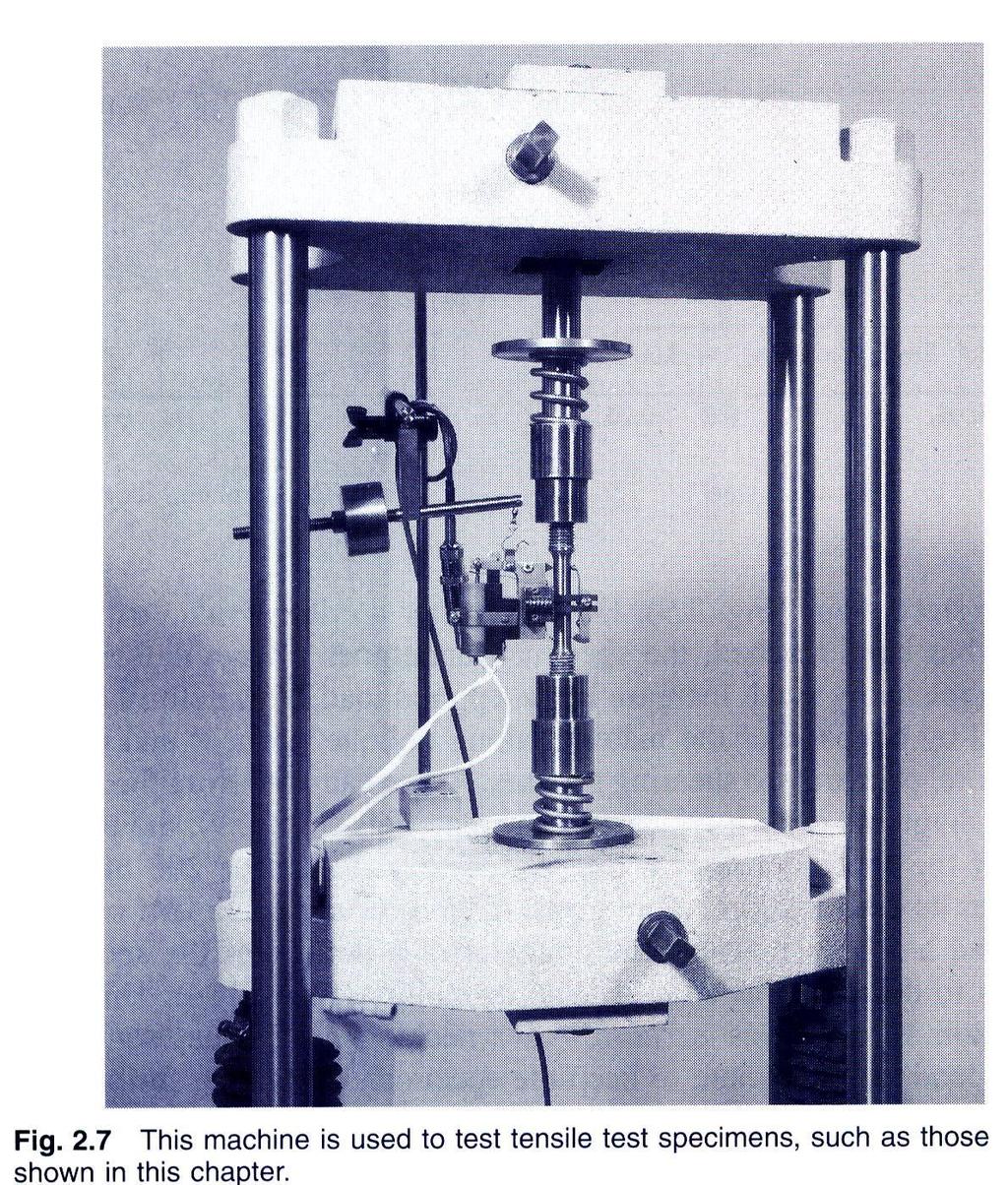
5 Stress-Strain Test - 5

6 Stress-Strain Diagram: Ductile Materials - 6

7 Stress-Strain Diagram: Brittle Materials - 7
8 Hooke s aw: Modulus of lasticity Below the yield stress Youngs Modulus or Modulus of lasticity Strength is affected by alloying, heat treating, and manufacturing process but stiffness (Modulus of lasticity) is not. - 8
9 lastic vs. lastic Behavior If the strain disappears when the stress is removed, the material is said to behave elastically. The largest stress for which this occurs is called the elastic limit. When the strain does not return to zero after the stress is removed, the material is said to behave plastically. - 9
10 Fatigue Fatigue properties are shown on S-N diagrams. member may fail due to fatigue at stress levels significantly below the ultimate strength if subjected to many loading cycles. When the stress is reduced below the endurance limit, fatigue failures do not occur for any number of cycles. - 10
11 Deformations Under xial oading From Hooke s aw: From the definition of strain: quating and solving for the deformation, With variations in loading, cross-section or material properties, i i i i i - 11

12 xample.01 SOUTION: Divide the rod into components at the load application points. 910 D 1.07in. 6 psi d 0.618in. Determine the deformation of the steel rod shown under the given loads. pply a free-body analysis on each component to determine the internal force valuate the total of the component deflections. - 1

13 SOUTION: Divide the rod into three components: pply free-body analysis to each component to determine internal forces, lb lb lb valuate total deflection, i i i i i in in. 0.9 in 16in. 0.in in. - 1
14 Sample roblem.1 SOUTION: The rigid bar BD is supported by two links B and CD. ink B is made of aluminum ( = 70 Ga) and has a cross-sectional area of 500 mm. ink CD is made of steel ( = 00 Ga) and has a cross-sectional area of (600 mm ). For the 0-kN force shown, determine the deflection a) of B, b) of D, and c) of. pply a free-body analysis to the bar BD to find the forces exerted by links B and DC. valuate the deformation of links B and DC or the displacements of B and D. Work out the geometry to find the deflection at given the deflections at B and D. - 14
15 Sample roblem.1 SOUTION: Free body: Bar BD Displacement of B: B 6010 N 0.m m 7010 a m M F F B 0 M CD D 0 B 0 0kN 0.6m 0 0kN 0.4m F 90kN tension F CD B 60kN compression 0.m 0.m Displacement of D: D B 0.514mm 9010 N 0.4m m 0010 a m D 0.00mm - 15
16 Sample roblem.1 Displacement of D: BB DD BH HD 0.514mm 0.00 mm x 7.7 mm 00mm x x DD 0.00mm H HD 1.98mm mm 7.7 mm 1.98mm - 16
17 Static Indeterminacy Structures for which internal forces and reactions cannot be determined from statics alone are said to be statically indeterminate. structure will be statically indeterminate whenever it is held by more supports than are required to maintain its equilibrium. Redundant reactions are replaced with unknown loads which along with the other loads must produce compatible deformations. Deformations due to actual loads and redundant reactions are determined separately and then added or superposed. R 0-17
18 xample.04 Determine the reactions at and B for the steel bar and loading shown, assuming a close fit at both supports before the loads are applied. SOUTION: Consider the reaction at B as redundant, release the bar from that support, and solve for the displacement at B due to the applied loads. Solve for the displacement at B due to the redundant reaction at B. Require that the displacements due to the loads and due to the redundant reaction be compatible, i.e., require that their sum be zero. Solve for the reaction at due to applied loads and the reaction found at B. - 18


19 xample.04 SOUTION: Solve for the displacement at B due to the applied loads with the redundant constraint released, i i i i i m N 0.150m Solve for the displacement at B due to the redundant constraint, δ R i R ii m i i B m R B 6 m N 6 m - 19

20 xample.04 Require that the displacements due to the loads and due to the redundant reaction be compatible, R B R N 577kN R B 0 Find the reaction at due to the loads and the reaction at B F R y 0 R kn 00kN 600kN 577kN R R B kn 577kN - 0


21 Thermal Stresses temperature change results in a change in length or thermal strain. There is no stress associated with the thermal strain unless the elongation is restrained by the supports. Treat the adal support as redundant and apply the principle of superposition. T T thermal T T 0 expansion coef. 0 The thermal deformation and the deformation from the redundant support must be compatible. T 0 T T - 1

, y z 0")
22 oisson s Ratio For a slender bar subjected to axial loading: x x y z 0 The elongation in the x-direction is accompanied by a contraction in the other directions. ssuming that the material is isotropic (no directional dependence), y z 0 oisson s ratio is defined as lateralstrain y n axial strain x z x -
23 Generalized Hooke s aw For an element subjected to multi-axial loading, the normal strain components resulting from the stress components may be determined from the principle of superposition. This requires: 1) strain is linearly related to stress ) deformations are small With these restrictions: x y z n x y n z n x y n z n n x y z -
24 hird Dilatation: Bulk Modulus Relative to the unstressed state, the change in volume is e x y 1 n x x z dilatation (change in volume y y z z x y per unit volume) For element subjected to uniform hydrostatic pressure, 1 n p e p k k bulk modulus 1 n Subjected to uniform pressure, dilatation must be negative, therefore 0 n 1 z
25 Shearing Strain cubic element subjected to a shear stress will deform into a rhomboid. The corresponding shear strain is quantified in terms of the change in angle between the sides, xy f xy plot of shear stress vs. shear strain is similar the previous plots of normal stress vs. normal strain except that the strength values are approximately half. For small strains, xy G xy yz G yz zx G where G is the modulus of rigidity or shear modulus. zx - 5

26 xample.10 rectangular block of material with modulus of rigidity G = 90 ksi is bonded to two rigid horizontal plates. The lower plate is fixed, while the upper plate is subjected to a horizontal force. Knowing that the upper plate moves through 0.04 in. under the action of the force, determine a) the average shearing strain in the material, and b) the force exerted on the plate. SOUTION: Determine the average angular deformation or shearing strain of the block. pply Hooke s law for shearing stress and strain to find the corresponding shearing stress. Use the definition of shearing stress to find the force. - 6

27 Determine the average angular deformation or shearing strain of the block. xy tan xy 0.04in. in. xy 0.00rad pply Hooke s law for shearing stress and strain to find the corresponding shearing stress. xy G 9010 psi 0.00rad 1800psi xy Use the definition of shearing stress to find the force. 1800psi8in..5in. 610 lb xy 6.0kips - 7

28 Relation mong, n, and G n axially loaded slender bar will elongate in the axial direction and contract in the transverse directions. n initially cubic element oriented as in top figure will deform into a rectangular parallelepiped. The axial load produces a normal strain. If the cubic element is oriented as in the bottom figure, it will deform into a rhombus. xial load also results in a shear strain. Components of normal and shear strain are related, G 1n - 8

29 Sample roblem.5 circle of diameter d = 9 in. is scribed on an unstressed aluminum plate of thickness t = /4 in. Forces acting in the plane of the plate later cause normal stresses x = 1 ksi and z = 0 ksi. For = 10x10 6 psi and n = 1/, determine the change in: a) the length of diameter B, b) the length of diameter CD, c) the thickness of the plate, and d) the volume of the plate. - 9
30 SOUTION: pply the generalized Hooke s aw to find the three components of normal strain. x y z x psi n x n x n y y n n z 1ksi 0 0ksi in./in. n z y in./in. z in./in. 1 valuate the deformation components. B d in./in. 9in. x C d D t y t z B in in./in. 9in. C D in in./in. 0.75in. t Find the change in volume e V x ev y z V in /in in in 0.187in - 0

31 Composite Materials Fiber-reinforced composite materials are formed from lamina of fibers of graphite, glass, or polymers embedded in a resin matrix. Normal stresses and strains are related by Hooke s aw but with directionally dependent moduli of elasticity, x n x xy x y x y n xz y y z x z z Transverse contractions are related by directionally dependent values of oisson s ratio, e.g., Materials with directionally dependent mechanical properties are anisotropic. z - 1


32 Saint-Venant s rinciple oads transmitted through rigid plates result in uniform distribution of stress and strain. Concentrated loads result in large stresses in the vicinity of the load application point. Stress and strain distributions become uniform at a relatively short distance from the load application points. Saint-Venant s rinciple: Stress distribution may be assumed independent of the mode of load application except in the immediate vicinity of load application points. -

33 Stress Concentration: Hole Discontinuities of cross section may result in high localized or concentrated stresses. K max ave -

34 Stress Concentration: Fillet - 4

35 xample.1 SOUTION: Determine the largest axial load that can be safely supported by a flat steel bar consisting of two portions, both 10 mm thick, and respectively 40 and 60 mm wide, connected by fillets of radius r = 8 mm. ssume an allowable normal stress of 165 Ma. Determine the geometric ratios and find the stress concentration factor from Fig..64b. Find the allowable average normal stress using the material allowable normal stress and the stress concentration factor. pply the definition of normal stress to find the allowable load. - 5
36 Determine the geometric ratios and find the stress concentration factor from Fig..64b. D d 60mm mm K 1.8 r d 8mm 40mm 0.0 Find the allowable average normal stress using the material allowable normal stress and the stress concentration factor. ave K max 165Ma Ma pply the definition of normal stress to find the allowable load. 40mm10mm90.7Ma ave 6.10 N 6.kN - 6
37 lastoplastic Materials revious analyses based on assumption of linear stress-strain relationship, i.e., stresses below the yield stress ssumption is good for brittle material which rupture without yielding If the yield stress of ductile materials is exceeded, then plastic deformations occur nalysis of plastic deformations is simplified by assuming an idealized elastoplastic material Deformations of an elastoplastic material are divided into elastic and plastic ranges ermanent deformations result from loading beyond the yield stress - 7

38 lastic Deformations max K ave Y Y K lastic deformation while maximum stress is less than yield stress Maximum stress is equal to the yield stress at the maximum elastic loading U Y K Y t loadings above the maximum elastic load, a region of plastic deformations develop near the hole s the loading increases, the plastic region expands until the section is at a uniform stress equal to the yield stress - 8
39 Residual Stresses When a single structural element is loaded uniformly beyond its yield stress and then unloaded, it is permanently deformed but all stresses disappear. This is not the general result. Residual stresses will remain in a structure after loading and unloading if - only part of the structure undergoes plastic deformation - different parts of the structure undergo different plastic deformations Residual stresses also result from the uneven heating or cooling of structures or structural elements - 9

40 xample.14,.15,.16 cylindrical rod is placed inside a tube of the same length. The ends of the rod and tube are attached to a rigid support on one side and a rigid plate on the other. The load on the rod-tube assembly is increased from zero to 5.7 kips and decreased back to zero. a) draw a load-deflection diagram for the rod-tube assembly b) determine the maximum elongation c) determine the permanent set d) calculate the residual stresses in the rod and tube. σ r r Y, r 0.075in ksi psi σ t t Y, t 0.100in ksi psi - 40
41 xample.14,.15,.16 a) draw a load-deflection diagram for the rodtube assembly Y, r Y, r r 6ksi0.075in.7 kips δ Y,r Y, r Y, r Y, r psi 0in. 610 psi - in. Y, t Y, t t 45ksi0.100in 4.5kips δ Y,t Y, t Y, t Y, t psi 0in psi - in. r t r t - 41
42 xample.14,.15,.16 b,c) determine the maximum elongation and permanent set at a load of = 5.7 kips, the rod has reached the plastic range while the tube is still in the elastic range r t t Y, r t t.7 kips r kips 0ksi 0.1in kips.0 kips t t t t psi 0in. psi max t 6010 in. the rod-tube assembly unloads along a line parallel to 0Y r 4.5kips m 15kips in. slope in. m max 5.7 kips kips in. in. p max in. p in. - 4
43 xample.14,.15,.16 calculate the residual stresses in the rod and tube. calculate the reverse stresses in the rod and tube caused by unloading and add them to the maximum stresses in. in in. in. r t t r psi psi 45.6ksi.8ksi residual, r residual, t t r t r ksi 9. 6ksi 0.8ksi 7.ksi - 4
MECHANICS OF MATERIALS
 Third CHTR Stress MCHNICS OF MTRIS Ferdinand. Beer. Russell Johnston, Jr. John T. DeWolf ecture Notes: J. Walt Oler Texas Tech University and Strain xial oading Contents Stress & Strain: xial oading Normal
MECHANICS OF MATERIALS
 Third E CHAPTER 2 Stress MECHANICS OF MATERIALS Ferdinand P. Beer E. Russell Johnston, Jr. John T. DeWolf Lecture Notes: J. Walt Oler Texas Tech University and Strain Axial Loading Contents Stress & Strain:
MECHANICS OF MATERIALS
 CHATR Stress MCHANICS OF MATRIALS and Strain Axial Loading Stress & Strain: Axial Loading Suitability of a structure or machine may depend on the deformations in the structure as well as the stresses induced
MECHANICS OF MATERIALS
 CHAPTER 2 MECHANICS OF MATERIALS Ferdinand P. Beer E. Russell Johnston, Jr. John T. DeWolf David F. Mazurek Lecture Notes: J. Walt Oler Texas Tech University Stress and Strain Axial Loading 2.1 An Introduction
EMA 3702 Mechanics & Materials Science (Mechanics of Materials) Chapter 2 Stress & Strain - Axial Loading
 Chapter 2 Stress & Strain - Axial Loading") MA 3702 Mechanics & Materials Science (Mechanics of Materials) Chapter 2 Stress & Strain - Axial Loading MA 3702 Mechanics & Materials Science Zhe Cheng (2018) 2 Stress & Strain - Axial Loading Statics
MA 3702 Mechanics & Materials Science (Mechanics of Materials) Chapter 2 Stress & Strain - Axial Loading MA 3702 Mechanics & Materials Science Zhe Cheng (2018) 2 Stress & Strain - Axial Loading Statics
[5] Stress and Strain
![[5] Stress and Strain](/thumbs/95/123344550.jpg "[5] Stress and Strain") [5] Stress and Strain Page 1 of 34 [5] Stress and Strain [5.1] Internal Stress of Solids [5.2] Design of Simple Connections (will not be covered in class) [5.3] Deformation and Strain [5.4] Hooke s Law
[5] Stress and Strain Page 1 of 34 [5] Stress and Strain [5.1] Internal Stress of Solids [5.2] Design of Simple Connections (will not be covered in class) [5.3] Deformation and Strain [5.4] Hooke s Law
Chapter 4-b Axially Loaded Members
 CIVL 222 STRENGTH OF MATERIALS Chapter 4-b Axially Loaded Members AXIAL LOADED MEMBERS Today s Objectives: Students will be able to: a) Determine the elastic deformation of axially loaded member b) Apply
Mechanics of Materials Primer
 Mechanics of Materials rimer Notation: A = area (net = with holes, bearing = in contact, etc...) b = total width of material at a horizontal section d = diameter of a hole D = symbol for diameter E = modulus
Mechanical Properties of Materials
 Mechanical Properties of Materials Strains Material Model Stresses Learning objectives Understand the qualitative and quantitative description of mechanical properties of materials. Learn the logic of
RODS: THERMAL STRESS AND STRESS CONCENTRATION
 RODS: HERML SRESS ND SRESS CONCENRION Example 5 rod of length L, cross-sectional area, and modulus of elasticity E, has been placed inside a tube of the same length L, but of cross-sectional area and modulus
MECHANICS OF MATERIALS
 2009 The McGraw-Hill Companies, Inc. All rights reserved. Fifth SI Edition CHAPTER 3 MECHANICS OF MATERIALS Ferdinand P. Beer E. Russell Johnston, Jr. John T. DeWolf David F. Mazurek Torsion Lecture Notes:
INTRODUCTION TO STRAIN
 SIMPLE STRAIN INTRODUCTION TO STRAIN In general terms, Strain is a geometric quantity that measures the deformation of a body. There are two types of strain: normal strain: characterizes dimensional changes,
2.32 Denoting by P the engineering strain in a tensile specimen, show that the true strain is P t 5 ln(1 1 P). 250 mm. 400 mm A B. 250 mm.
. 250 mm. 400 mm A B. 250 mm.") 2.28 ach of the four vertical links connecting the two rigid horizontal members is made of aluminum ( 5 70 Ga) and has a uniform rectangular cross section of 10 3 40 mm. For the loading shown, determine
2.28 ach of the four vertical links connecting the two rigid horizontal members is made of aluminum ( 5 70 Ga) and has a uniform rectangular cross section of 10 3 40 mm. For the loading shown, determine
Samantha Ramirez, MSE. Stress. The intensity of the internal force acting on a specific plane (area) passing through a point. F 2
 passing through a point. F 2") Samantha Ramirez, MSE Stress The intensity of the internal force acting on a specific plane (area) passing through a point. Δ ΔA Δ z Δ 1 2 ΔA Δ x Δ y ΔA is an infinitesimal size area with a uniform force
Samantha Ramirez, MSE Stress The intensity of the internal force acting on a specific plane (area) passing through a point. Δ ΔA Δ z Δ 1 2 ΔA Δ x Δ y ΔA is an infinitesimal size area with a uniform force
MECE 3321 MECHANICS OF SOLIDS CHAPTER 3
 MECE 3321 MECHANICS OF SOLIDS CHAPTER 3 Samantha Ramirez TENSION AND COMPRESSION TESTS Tension and compression tests are used primarily to determine the relationship between σ avg and ε avg in any material.
Mechanics of Materials
 Mechanics of Materials Notation: a = acceleration = area (net = with holes, bearing = in contact, etc...) SD = allowable stress design d = diameter of a hole = calculus symbol for differentiation e = change
NORMAL STRESS. The simplest form of stress is normal stress/direct stress, which is the stress perpendicular to the surface on which it acts.
 NORMAL STRESS The simplest form of stress is normal stress/direct stress, which is the stress perpendicular to the surface on which it acts. σ = force/area = P/A where σ = the normal stress P = the centric
MECHANICS OF MATERIALS
 CHTER MECHNICS OF MTERILS 10 Ferdinand. Beer E. Russell Johnston, Jr. Columns John T. DeWolf cture Notes: J. Walt Oler Texas Tech University 006 The McGraw-Hill Companies, Inc. ll rights reserved. Columns
ME 243. Mechanics of Solids
 ME 243 Mechanics of Solids Lecture 2: Stress and Strain Ahmad Shahedi Shakil Lecturer, Dept. of Mechanical Engg, BUET E-mail: sshakil@me.buet.ac.bd, shakil6791@gmail.com Website: teacher.buet.ac.bd/sshakil
Constitutive Equations (Linear Elasticity)
") Constitutive quations (Linear lasticity) quations that characterize the physical properties of the material of a system are called constitutive equations. It is possible to find the applied stresses knowing
Constitutive quations (Linear lasticity) quations that characterize the physical properties of the material of a system are called constitutive equations. It is possible to find the applied stresses knowing
Chapter 3. Load and Stress Analysis
 Chapter 3 Load and Stress Analysis 2 Shear Force and Bending Moments in Beams Internal shear force V & bending moment M must ensure equilibrium Fig. 3 2 Sign Conventions for Bending and Shear Fig. 3 3
Purpose of this Guide: To thoroughly prepare students for the exact types of problems that will be on Exam 3.
 ES230 STRENGTH OF MTERILS Exam 3 Study Guide Exam 3: Wednesday, March 8 th in-class Updated 3/3/17 Purpose of this Guide: To thoroughly prepare students for the exact types of problems that will be on
MECHANICS OF MATERIALS
 Third E CHAPTER 1 Introduction MECHANICS OF MATERIALS Ferdinand P. Beer E. Russell Johnston, Jr. John T. DeWolf Lecture Notes: J. Walt Oler Texas Tech University Concept of Stress Contents Concept of Stress
MECHANICS OF MATERIALS Sample Problem 4.2
 Sample Problem 4. SOLUTON: Based on the cross section geometry, calculate the location of the section centroid and moment of inertia. ya ( + Y Ad ) A A cast-iron machine part is acted upon by a kn-m couple.
MECHANICS OF MATERIALS
 GE SI CHAPTER 3 MECHANICS OF MATERIALS Ferdinand P. Beer E. Russell Johnston, Jr. John T. DeWolf David F. Mazurek Torsion Lecture Notes: J. Walt Oler Texas Tech University Torsional Loads on Circular Shafts
five Mechanics of Materials 1 ARCHITECTURAL STRUCTURES: FORM, BEHAVIOR, AND DESIGN DR. ANNE NICHOLS SUMMER 2017 lecture
 ARCHITECTURAL STRUCTURES: FORM, BEHAVIOR, AND DESIGN DR. ANNE NICHOLS SUMMER 2017 lecture five mechanics www.carttalk.com of materials Mechanics of Materials 1 Mechanics of Materials MECHANICS MATERIALS
Mechanics of Materials II. Chapter III. A review of the fundamental formulation of stress, strain, and deflection
 Mechanics of Materials II Chapter III A review of the fundamental formulation of stress, strain, and deflection Outline Introduction Assumtions and limitations Axial loading Torsion of circular shafts
A concrete cylinder having a a diameter of of in. mm and elasticity. Stress and Strain: Stress and Strain: 0.
 2011 earson Education, Inc., Upper Saddle River, NJ. ll rights reserved. This material is protected under all copyright laws as they currently 8 1. 3 1. concrete cylinder having a a diameter of of 6.00
MECHANICS OF MATERIALS Poisson s Ratio
 Poisson s Raio For a slender bar subjeced o axial loading: ε x x y 0 The elongaion in he x-direcion i is accompanied by a conracion in he oher direcions. Assuming ha he maerial is isoropic (no direcional
MECHANICS OF MATERIALS
 Third E CHAPTER 6 Shearing MECHANCS OF MATERALS Ferdinand P. Beer E. Russell Johnston, Jr. John T. DeWolf Lecture Notes: J. Walt Oler Texas Tech University Stresses in Beams and Thin- Walled Members Shearing
Tuesday, February 11, Chapter 3. Load and Stress Analysis. Dr. Mohammad Suliman Abuhaiba, PE
 1 Chapter 3 Load and Stress Analysis 2 Chapter Outline Equilibrium & Free-Body Diagrams Shear Force and Bending Moments in Beams Singularity Functions Stress Cartesian Stress Components Mohr s Circle for
The science of elasticity
 The science of elasticity In 1676 Hooke realized that 1.Every kind of solid changes shape when a mechanical force acts on it. 2.It is this change of shape which enables the solid to supply the reaction
4.MECHANICAL PROPERTIES OF MATERIALS
 4.MECHANICAL PROPERTIES OF MATERIALS The diagram representing the relation between stress and strain in a given material is an important characteristic of the material. To obtain the stress-strain diagram
Chapter 5 CENTRIC TENSION OR COMPRESSION ( AXIAL LOADING )
") Chapter 5 CENTRIC TENSION OR COMPRESSION ( AXIAL LOADING ) 5.1 DEFINITION A construction member is subjected to centric (axial) tension or compression if in any cross section the single distinct stress
Chapter 5 CENTRIC TENSION OR COMPRESSION ( AXIAL LOADING ) 5.1 DEFINITION A construction member is subjected to centric (axial) tension or compression if in any cross section the single distinct stress
(48) CHAPTER 3: TORSION
 CHAPTER 3: TORSION") (48) CHAPTER 3: TORSION Introduction: In this chapter structural members and machine parts that are in torsion will be considered. More specifically, you will analyze the stresses and strains in members
(48) CHAPTER 3: TORSION Introduction: In this chapter structural members and machine parts that are in torsion will be considered. More specifically, you will analyze the stresses and strains in members
EMA 3702 Mechanics & Materials Science (Mechanics of Materials) Chapter 3 Torsion
 Chapter 3 Torsion") EMA 3702 Mechanics & Materials Science (Mechanics of Materials) Chapter 3 Torsion Introduction Stress and strain in components subjected to torque T Circular Cross-section shape Material Shaft design Non-circular
EMA 3702 Mechanics & Materials Science (Mechanics of Materials) Chapter 3 Torsion Introduction Stress and strain in components subjected to torque T Circular Cross-section shape Material Shaft design Non-circular
MECHANICS OF MATERIALS
 STATICS AND MECHANICS OF MATERIALS Ferdinand P. Beer E. Russell Johnston, Jr, John T. DeWolf David E Mazurek \Cawect Mc / iur/» Craw SugomcT Hilt Introduction 1 1.1 What is Mechanics? 2 1.2 Fundamental
ME Final Exam. PROBLEM NO. 4 Part A (2 points max.) M (x) y. z (neutral axis) beam cross-sec+on. 20 kip ft. 0.2 ft. 10 ft. 0.1 ft.
 M (x) y. z (neutral axis) beam cross-sec+on. 20 kip ft. 0.2 ft. 10 ft. 0.1 ft.") ME 323 - Final Exam Name December 15, 2015 Instructor (circle) PROEM NO. 4 Part A (2 points max.) Krousgrill 11:30AM-12:20PM Ghosh 2:30-3:20PM Gonzalez 12:30-1:20PM Zhao 4:30-5:20PM M (x) y 20 kip ft 0.2
ME 323 - Final Exam Name December 15, 2015 Instructor (circle) PROEM NO. 4 Part A (2 points max.) Krousgrill 11:30AM-12:20PM Ghosh 2:30-3:20PM Gonzalez 12:30-1:20PM Zhao 4:30-5:20PM M (x) y 20 kip ft 0.2
ME 2570 MECHANICS OF MATERIALS
 ME 2570 MECHANICS OF MATERIALS Chapter III. Mechanical Properties of Materials 1 Tension and Compression Test The strength of a material depends on its ability to sustain a load without undue deformation
Chapter Two: Mechanical Properties of materials
 Chapter Two: Mechanical Properties of materials Time : 16 Hours An important consideration in the choice of a material is the way it behave when subjected to force. The mechanical properties of a material
Tensile stress strain curves for different materials. Shows in figure below
 Tensile stress strain curves for different materials. Shows in figure below Furthermore, the modulus of elasticity of several materials effected by increasing temperature, as is shown in Figure Asst. Lecturer
Free Body Diagram: Solution: The maximum load which can be safely supported by EACH of the support members is: ANS: A =0.217 in 2
 Problem 10.9 The angle β of the system in Problem 10.8 is 60. The bars are made of a material that will safely support a tensile normal stress of 8 ksi. Based on this criterion, if you want to design the
Mechanical Design in Optical Engineering. For a prismatic bar of length L in tension by axial forces P we have determined:
 Deformation of Axial Members For a prismatic bar of length L in tension by axial forces P we have determined: σ = P A δ ε = L It is important to recall that the load P must act on the centroid of the cross
Problem " Â F y = 0. ) R A + 2R B + R C = 200 kn ) 2R A + 2R B = 200 kn [using symmetry R A = R C ] ) R A + R B = 100 kn
![Problem  F y = 0. ) R A + 2R B + R C = 200 kn ) 2R A + 2R B = 200 kn [using symmetry R A = R C ] ) R A + R B = 100 kn](/thumbs/88/116790835.jpg "Problem  F y = 0. ) R A + 2R B + R C = 200 kn ) 2R A + 2R B = 200 kn [using symmetry R A = R C ] ) R A + R B = 100 kn") Problem 0. Three cables are attached as shown. Determine the reactions in the supports. Assume R B as redundant. Also, L AD L CD cos 60 m m. uation of uilibrium: + "  F y 0 ) R A cos 60 + R B + R C cos
Problem 0. Three cables are attached as shown. Determine the reactions in the supports. Assume R B as redundant. Also, L AD L CD cos 60 m m. uation of uilibrium: + " Â F y 0 ) R A cos 60 + R B + R C cos
Solid Mechanics Chapter 1: Tension, Compression and Shear
 Solid Mechanics Chapter 1: Tension, Compression and Shear Dr. Imran Latif Department of Civil and Environmental Engineering College of Engineering University of Nizwa (UoN) 1 Why do we study Mechanics
Theory at a Glance (for IES, GATE, PSU)
") 1. Stress and Strain Theory at a Glance (for IES, GATE, PSU) 1.1 Stress () When a material is subjected to an external force, a resisting force is set up within the component. The internal resistance force
1. Stress and Strain Theory at a Glance (for IES, GATE, PSU) 1.1 Stress () When a material is subjected to an external force, a resisting force is set up within the component. The internal resistance force
CONSTITUTIVE RELATIONS FOR LINEAR ELASTIC SOLIDS
 Chapter 9 CONSTITUTIV RLATIONS FOR LINAR LASTIC SOLIDS Figure 9.1: Hooke memorial window, St. Helen s, Bishopsgate, City of London 211 212 CHAPTR 9. CONSTITUTIV RLATIONS FOR LINAR LASTIC SOLIDS 9.1 Mechanical
Direct and Shear Stress
 Direct and Shear Stress 1 Direct & Shear Stress When a body is pulled by a tensile force or crushed by a compressive force, the loading is said to be direct. Direct stresses are also found to arise when
MECHANICS OF MATERIALS
 CHAPTER 6 MECHANCS OF MATERALS Ferdinand P. Beer E. Russell Johnston, Jr. John T. DeWolf David F. Mazurek Lecture Notes: J. Walt Oler Texas Tech University Shearing Stresses in Beams and Thin- Walled Members
Strength of Materials (15CV 32)
") Strength of Materials (15CV 32) Module 1 : Simple Stresses and Strains Dr. H. Ananthan, Professor, VVIET,MYSURU 8/21/2017 Introduction, Definition and concept and of stress and strain. Hooke s law, Stress-Strain
Strength of Materials (15CV 32) Module 1 : Simple Stresses and Strains Dr. H. Ananthan, Professor, VVIET,MYSURU 8/21/2017 Introduction, Definition and concept and of stress and strain. Hooke s law, Stress-Strain
COURSE TITLE : APPLIED MECHANICS & STRENGTH OF MATERIALS COURSE CODE : 4017 COURSE CATEGORY : A PERIODS/WEEK : 6 PERIODS/ SEMESTER : 108 CREDITS : 5
 COURSE TITLE : APPLIED MECHANICS & STRENGTH OF MATERIALS COURSE CODE : 4017 COURSE CATEGORY : A PERIODS/WEEK : 6 PERIODS/ SEMESTER : 108 CREDITS : 5 TIME SCHEDULE MODULE TOPICS PERIODS 1 Simple stresses
MECHANICS OF MATERIALS. Prepared by Engr. John Paul Timola
 MECHANICS OF MATERIALS Prepared by Engr. John Paul Timola Mechanics of materials branch of mechanics that studies the internal effects of stress and strain in a solid body. stress is associated with the
five mechanics of materials Mechanics of Materials Mechanics of Materials Knowledge Required MECHANICS MATERIALS
 RCHITECTUR STRUCTURES: FORM, BEHVIOR, ND DESIGN DR. NNE NICHOS SUMMER 2014 Mechanics o Materials MECHNICS MTERIS lecture ive mechanics o materials www.carttalk.com Mechanics o Materials 1 rchitectural
MECHANICS OF MATERIALS
 00 The McGraw-Hill Companies, Inc. All rights reserved. T Edition CHAPTER MECHANICS OF MATERIALS Ferdinand P. Beer E. Russell Johnston, Jr. John T. DeWolf Lecture Notes: J. Walt Oler Teas Tech Universit
Downloaded from Downloaded from / 1
 PURWANCHAL UNIVERSITY III SEMESTER FINAL EXAMINATION-2002 LEVEL : B. E. (Civil) SUBJECT: BEG256CI, Strength of Material Full Marks: 80 TIME: 03:00 hrs Pass marks: 32 Candidates are required to give their
MECHANICS OF MATERIALS
 Fourth Edton CHTER MECHNICS OF MTERIS Ferdnand. Beer E. Russell Johnston, Jr. John T. DeWolf ecture Notes: J. Walt Oler Texas Tech Unversty Stress and Stran xal oadng Contents Stress & Stran: xal oadng
Stress Analysis Lecture 3 ME 276 Spring Dr./ Ahmed Mohamed Nagib Elmekawy
 Stress Analysis Lecture 3 ME 276 Spring 2017-2018 Dr./ Ahmed Mohamed Nagib Elmekawy Axial Stress 2 Beam under the action of two tensile forces 3 Beam under the action of two tensile forces 4 Shear Stress
CHAPTER 4: BENDING OF BEAMS
 (74) CHAPTER 4: BENDING OF BEAMS This chapter will be devoted to the analysis of prismatic members subjected to equal and opposite couples M and M' acting in the same longitudinal plane. Such members are
MAAE 2202 A. Come to the PASS workshop with your mock exam complete. During the workshop you can work with other students to review your work.
 It is most beneficial to you to write this mock final exam UNDER EXAM CONDITIONS. This means: Complete the exam in 3 hours. Work on your own. Keep your textbook closed. Attempt every question. After the
MECHANICS OF MATERIALS
 CHAPTER MECHANCS OF MATERALS Ferdinand P. Beer E. Russell Johnston, Jr. John T. DeWolf Lecture Notes: J. Walt Oler Texas Tech University Shearing Stresses in Beams and Thin- Walled Members 006 The McGraw-Hill
four mechanics of materials Mechanics of Materials Mechanics of Materials Knowledge Required MECHANICS MATERIALS
 EEMENTS OF RCHITECTUR STRUCTURES: FORM, BEHVIOR, ND DESIGN DR. NNE NICHOS SRING 2016 Mechanics o Materials MECHNICS MTERIS lecture our mechanics o materials www.carttalk.com Mechanics o Materials 1 S2009abn
ME 207 Material Science I
 ME 207 Material Science I Chapter 3 Properties in Tension and Compression Dr. İbrahim H. Yılmaz http://web.adanabtu.edu.tr/iyilmaz Automotive Engineering Adana Science and Technology University Introduction
QUESTION BANK SEMESTER: III SUBJECT NAME: MECHANICS OF SOLIDS
 QUESTION BANK SEMESTER: III SUBJECT NAME: MECHANICS OF SOLIDS UNIT 1- STRESS AND STRAIN PART A (2 Marks) 1. Define longitudinal strain and lateral strain. 2. State Hooke s law. 3. Define modular ratio,
[7] Torsion. [7.1] Torsion. [7.2] Statically Indeterminate Torsion. [7] Torsion Page 1 of 21
![[7] Torsion. [7.1] Torsion. [7.2] Statically Indeterminate Torsion. [7] Torsion Page 1 of 21](/thumbs/88/115835122.jpg "[7] Torsion. [7.1] Torsion. [7.2] Statically Indeterminate Torsion. [7] Torsion Page 1 of 21") [7] Torsion Page 1 of 21 [7] Torsion [7.1] Torsion [7.2] Statically Indeterminate Torsion [7] Torsion Page 2 of 21 [7.1] Torsion SHEAR STRAIN DUE TO TORSION 1) A shaft with a circular cross section is
[7] Torsion Page 1 of 21 [7] Torsion [7.1] Torsion [7.2] Statically Indeterminate Torsion [7] Torsion Page 2 of 21 [7.1] Torsion SHEAR STRAIN DUE TO TORSION 1) A shaft with a circular cross section is
QUESTION BANK DEPARTMENT: CIVIL SEMESTER: III SUBJECT CODE: CE2201 SUBJECT NAME: MECHANICS OF SOLIDS UNIT 1- STRESS AND STRAIN PART A
 DEPARTMENT: CIVIL SUBJECT CODE: CE2201 QUESTION BANK SEMESTER: III SUBJECT NAME: MECHANICS OF SOLIDS UNIT 1- STRESS AND STRAIN PART A (2 Marks) 1. Define longitudinal strain and lateral strain. 2. State
: APPLIED MECHANICS & STRENGTH OF MATERIALS COURSE CODE : 4021 COURSE CATEGORY : A PERIODS/ WEEK : 5 PERIODS/ SEMESTER : 75 CREDIT : 5 TIME SCHEDULE
 COURSE TITLE : APPLIED MECHANICS & STRENGTH OF MATERIALS COURSE CODE : 4021 COURSE CATEGORY : A PERIODS/ WEEK : 5 PERIODS/ SEMESTER : 75 CREDIT : 5 TIME SCHEDULE MODULE TOPIC PERIODS 1 Simple stresses
STRESS, STRAIN AND DEFORMATION OF SOLIDS
 VELAMMAL COLLEGE OF ENGINEERING AND TECHNOLOGY, MADURAI 625009 DEPARTMENT OF CIVIL ENGINEERING CE8301 STRENGTH OF MATERIALS I -------------------------------------------------------------------------------------------------------------------------------
High Tech High Top Hat Technicians. An Introduction to Solid Mechanics. Is that supposed to bend there?
 High Tech High Top Hat Technicians An Introduction to Solid Mechanics Or Is that supposed to bend there? Why don't we fall through the floor? The power of any Spring is in the same proportion with the
RODS: STATICALLY INDETERMINATE MEMBERS
 RODS: STTICLLY INDETERMINTE MEMERS Statically Indeterminate ackground In all of the problems discussed so far, it was possible to determine the forces and stresses in the members by utilizing the equations
NAME: Given Formulae: Law of Cosines: Law of Sines:
 NME: Given Formulae: Law of Cosines: EXM 3 PST PROBLEMS (LESSONS 21 TO 28) 100 points Thursday, November 16, 2017, 7pm to 9:30, Room 200 You are allowed to use a calculator and drawing equipment, only.
Chapter 4 Deflection and Stiffness
 Chapter 4 Deflection and Stiffness Asst. Prof. Dr. Supakit Rooppakhun Chapter Outline Deflection and Stiffness 4-1 Spring Rates 4-2 Tension, Compression, and Torsion 4-3 Deflection Due to Bending 4-4 Beam
CHAPTER OBJECTIVES CHAPTER OUTLINE. 4. Axial Load
 CHAPTER OBJECTIVES Determine deformation of axially loaded members Develop a method to find support reactions when it cannot be determined from euilibrium euations Analyze the effects of thermal stress
MECHANICS OF MATERIALS
 Fifth SI Edition CHTER 1 MECHNICS OF MTERILS Ferdinand. Beer E. Russell Johnston, Jr. John T. DeWolf David F. Mazurek Introduction Concept of Stress Lecture Notes: J. Walt Oler Teas Tech University Contents
UNIT 1 STRESS STRAIN AND DEFORMATION OF SOLIDS, STATES OF STRESS 1. Define stress. When an external force acts on a body, it undergoes deformation.
 UNIT 1 STRESS STRAIN AND DEFORMATION OF SOLIDS, STATES OF STRESS 1. Define stress. When an external force acts on a body, it undergoes deformation. At the same time the body resists deformation. The magnitude
KINGS COLLEGE OF ENGINEERING DEPARTMENT OF MECHANICAL ENGINEERING QUESTION BANK. Subject code/name: ME2254/STRENGTH OF MATERIALS Year/Sem:II / IV
 KINGS COLLEGE OF ENGINEERING DEPARTMENT OF MECHANICAL ENGINEERING QUESTION BANK Subject code/name: ME2254/STRENGTH OF MATERIALS Year/Sem:II / IV UNIT I STRESS, STRAIN DEFORMATION OF SOLIDS PART A (2 MARKS)
MATERIALS FOR CIVIL AND CONSTRUCTION ENGINEERS
 MATERIALS FOR CIVIL AND CONSTRUCTION ENGINEERS 3 rd Edition Michael S. Mamlouk Arizona State University John P. Zaniewski West Virginia University Solution Manual FOREWORD This solution manual includes
Torsion of Shafts Learning objectives
 Torsion of Shafts Shafts are structural members with length significantly greater than the largest cross-sectional dimension used in transmitting torque from one plane to another. Learning objectives Understand
Structural Analysis I Chapter 4 - Torsion TORSION
 ORSION orsional stress results from the action of torsional or twisting moments acting about the longitudinal axis of a shaft. he effect of the application of a torsional moment, combined with appropriate
Chapter 3. Load and Stress Analysis. Lecture Slides
 Lecture Slides Chapter 3 Load and Stress Analysis 2015 by McGraw Hill Education. This is proprietary material solely for authorized instructor use. Not authorized for sale or distribution in any manner.
March 24, Chapter 4. Deflection and Stiffness. Dr. Mohammad Suliman Abuhaiba, PE
 Chapter 4 Deflection and Stiffness 1 2 Chapter Outline Spring Rates Tension, Compression, and Torsion Deflection Due to Bending Beam Deflection Methods Beam Deflections by Superposition Strain Energy Castigliano
Homework No. 1 MAE/CE 459/559 John A. Gilbert, Ph.D. Fall 2004
 Homework No. 1 MAE/CE 459/559 John A. Gilbert, Ph.D. 1. A beam is loaded as shown. The dimensions of the cross section appear in the insert. the figure. Draw a complete free body diagram showing an equivalent
M. Vable Mechanics of Materials: Chapter 5. Torsion of Shafts
 Torsion of Shafts Shafts are structural members with length significantly greater than the largest cross-sectional dimension used in transmitting torque from one plane to another. Learning objectives Understand
R13. II B. Tech I Semester Regular Examinations, Jan MECHANICS OF SOLIDS (Com. to ME, AME, AE, MTE) PART-A
 PART-A") SET - 1 II B. Tech I Semester Regular Examinations, Jan - 2015 MECHANICS OF SOLIDS (Com. to ME, AME, AE, MTE) Time: 3 hours Max. Marks: 70 Note: 1. Question Paper consists of two parts (Part-A and Part-B)
SET - 1 II B. Tech I Semester Regular Examinations, Jan - 2015 MECHANICS OF SOLIDS (Com. to ME, AME, AE, MTE) Time: 3 hours Max. Marks: 70 Note: 1. Question Paper consists of two parts (Part-A and Part-B)
2. Rigid bar ABC supports a weight of W = 50 kn. Bar ABC is pinned at A and supported at B by rod (1). What is the axial force in rod (1)?
. What is the axial force in rod (1)?") IDE 110 S08 Test 1 Name: 1. Determine the internal axial forces in segments (1), (2) and (3). (a) N 1 = kn (b) N 2 = kn (c) N 3 = kn 2. Rigid bar ABC supports a weight of W = 50 kn. Bar ABC is pinned at
IDE 110 S08 Test 1 Name: 1. Determine the internal axial forces in segments (1), (2) and (3). (a) N 1 = kn (b) N 2 = kn (c) N 3 = kn 2. Rigid bar ABC supports a weight of W = 50 kn. Bar ABC is pinned at
Name (Print) ME Mechanics of Materials Exam # 1 Date: October 5, 2016 Time: 8:00 10:00 PM
 ME Mechanics of Materials Exam # 1 Date: October 5, 2016 Time: 8:00 10:00 PM") Name (Print) (Last) (First) Instructions: ME 323 - Mechanics of Materials Exam # 1 Date: October 5, 2016 Time: 8:00 10:00 PM Circle your lecturer s name and your class meeting time. Gonzalez Krousgrill
Name (Print) (Last) (First) Instructions: ME 323 - Mechanics of Materials Exam # 1 Date: October 5, 2016 Time: 8:00 10:00 PM Circle your lecturer s name and your class meeting time. Gonzalez Krousgrill
Mechanical properties 1 Elastic behaviour of materials
 MME131: Lecture 13 Mechanical properties 1 Elastic behaviour of materials A. K. M. B. Rashid Professor, Department of MME BUET, Dhaka Today s Topics Deformation of material under the action of a mechanical
Course: US01CPHY01 UNIT 1 ELASTICITY I Introduction:
 Course: US0CPHY0 UNIT ELASTICITY I Introduction: If the distance between any two points in a body remains invariable, the body is said to be a rigid body. In practice it is not possible to have a perfectly
STATICALLY INDETERMINATE STRUCTURES
 STATICALLY INDETERMINATE STRUCTURES INTRODUCTION Generally the trusses are supported on (i) a hinged support and (ii) a roller support. The reaction components of a hinged support are two (in horizontal
CHAPTER THREE SYMMETRIC BENDING OF CIRCLE PLATES
 CHAPTER THREE SYMMETRIC BENDING OF CIRCLE PLATES * Governing equations in beam and plate bending ** Solution by superposition 1.1 From Beam Bending to Plate Bending 1.2 Governing Equations For Symmetric
Unit I Stress and Strain
 Unit I Stress and Strain Stress and strain at a point Tension, Compression, Shear Stress Hooke s Law Relationship among elastic constants Stress Strain Diagram for Mild Steel, TOR steel, Concrete Ultimate
STANDARD SAMPLE. Reduced section " Diameter. Diameter. 2" Gauge length. Radius
 MATERIAL PROPERTIES TENSILE MEASUREMENT F l l 0 A 0 F STANDARD SAMPLE Reduced section 2 " 1 4 0.505" Diameter 3 4 " Diameter 2" Gauge length 3 8 " Radius TYPICAL APPARATUS Load cell Extensometer Specimen
D : SOLID MECHANICS. Q. 1 Q. 9 carry one mark each. Q.1 Find the force (in kn) in the member BH of the truss shown.
 in the member BH of the truss shown.") D : SOLID MECHANICS Q. 1 Q. 9 carry one mark each. Q.1 Find the force (in kn) in the member BH of the truss shown. Q.2 Consider the forces of magnitude F acting on the sides of the regular hexagon having
D : SOLID MECHANICS Q. 1 Q. 9 carry one mark each. Q.1 Find the force (in kn) in the member BH of the truss shown. Q.2 Consider the forces of magnitude F acting on the sides of the regular hexagon having
STRENGTH OF MATERIALS-I. Unit-1. Simple stresses and strains
 STRENGTH OF MATERIALS-I Unit-1 Simple stresses and strains 1. What is the Principle of surveying 2. Define Magnetic, True & Arbitrary Meridians. 3. Mention different types of chains 4. Differentiate between
9 MECHANICAL PROPERTIES OF SOLIDS
 9 MECHANICAL PROPERTIES OF SOLIDS Deforming force Deforming force is the force which changes the shape or size of a body. Restoring force Restoring force is the internal force developed inside the body
N = Shear stress / Shear strain
 UNIT - I 1. What is meant by factor of safety? [A/M-15] It is the ratio between ultimate stress to the working stress. Factor of safety = Ultimate stress Permissible stress 2. Define Resilience. [A/M-15]
MECHANICS OF MATERIALS
 009 The McGraw-Hill Companies, Inc. All rights reserved. Fifth SI Edition CHAPTER 7 MECHANICS OF MATERIALS Ferdinand P. Beer E. Russell Johnston, Jr. John T. DeWolf David F. Mazurek Transformations of
MECE 3321 MECHANICS OF SOLIDS CHAPTER 1
 MECE 3321 MECHANICS O SOLIDS CHAPTER 1 Samantha Ramirez, MSE WHAT IS MECHANICS O MATERIALS? Rigid Bodies Statics Dynamics Mechanics Deformable Bodies Solids/Mech. Of Materials luids 1 WHAT IS MECHANICS
Stress-Strain Behavior
 Stress-Strain Behavior 6.3 A specimen of aluminum having a rectangular cross section 10 mm 1.7 mm (0.4 in. 0.5 in.) is pulled in tension with 35,500 N (8000 lb f ) force, producing only elastic deformation.
PDDC 1 st Semester Civil Engineering Department Assignments of Mechanics of Solids [ ] Introduction, Fundamentals of Statics
![PDDC 1 st Semester Civil Engineering Department Assignments of Mechanics of Solids [ ] Introduction, Fundamentals of Statics](/thumbs/92/109382806.jpg "PDDC 1 st Semester Civil Engineering Department Assignments of Mechanics of Solids [ ] Introduction, Fundamentals of Statics") Page1 PDDC 1 st Semester Civil Engineering Department Assignments of Mechanics of Solids [2910601] Introduction, Fundamentals of Statics 1. Differentiate between Scalar and Vector quantity. Write S.I.
Page1 PDDC 1 st Semester Civil Engineering Department Assignments of Mechanics of Solids [2910601] Introduction, Fundamentals of Statics 1. Differentiate between Scalar and Vector quantity. Write S.I.
Use Hooke s Law (as it applies in the uniaxial direction),
,") 0.6 STRSS-STRAIN RLATIONSHIP Use the principle of superposition Use Poisson s ratio, v lateral longitudinal Use Hooke s Law (as it applies in the uniaxial direction), x x v y z, y y vx z, z z vx y Copyright
0.6 STRSS-STRAIN RLATIONSHIP Use the principle of superposition Use Poisson s ratio, v lateral longitudinal Use Hooke s Law (as it applies in the uniaxial direction), x x v y z, y y vx z, z z vx y Copyright