Bending Deflection.
|
|
|
- Merryl Bruce
- 6 years ago
- Views:
Transcription
1 ending Deflection
2 ontents The Elastic urve, Deflection & Slope ( 挠曲线 挠度和转角 ) Differential Euation of the Elastic urve( 挠曲线微分方程 ) Deflection & Slope by Integration( 积分法求挠度和转角 ) oundary onditions( 边界条件 ) Symmetry onditions( 对称性条件 ) ontinuity onditions( 连续性条件 ) Direct Integration from Distributed Loads( 直接由分布荷载积分求挠度和转角 ) Direct Integration from Transverse Loads( 直接由剪力积分求挠度和转角 ) Deformations in a Transverse ross Section( 梁横截面内的变形 ) urvature Shortening( 梁由于弯曲造成的轴向位移 )
3 ontents Deflection & Slope by Superposition( 叠加法求挠度和转角 ) Superposition of Loads( 荷载叠加法 ) Superposition of Rigidized Structures( 刚化叠加法 ) ombined Superposition( 荷载和变形组合叠加法 ) Deflection & Slope by Singular Functions( 奇异函数法求挠度和转角 ) Deflection & Slope by Moment-rea Theorems( 图乘法求挠度和转角 ) Stiffness ondition( 刚度条件 ) Ways to Increase Fleural Rigidity( 梁的刚度优化设计 ) ending Strain Energy( 弯曲应变能 )
4 The Elastic urve, Deflection and Slope The elastic curve: beam ais under bending, reuired to determine beam deflection and slope. ending deflections ( = f()): vertical deflection of the neutral surface, defined as donard positive / upard negative. Slope (θ = θ() tan(θ) = d/d): rotation of cross-sections, defined as clockise positive / counter clockise negative Deflection curve 4
5 Differential Euation of the Elastic urve urvature of the neutral surface 1 ( ) M M( ) EI z M 0 0 M 1 / ( ) (1 ) M M 0 0 M EI M EI: fleural rigidity The negative sign is due to the particular choice of the -ais. 5
6 Deflection and Slope by Integration EI M() EI M ( ) d EI M ( )dd D onventionally assuming constant fleural rigidity (EI) Integration constants and D can be determined from boundary conditions, symmetry conditions, and continuity conditions. 6

7 oundary onditions Simple eams Deflections are restrained at the hinged/rolled supports 0; 0 7

8 oundary onditions- antilever eams oth the deflection and rotation are restrained at the clamped end 0; 0 8
 0")
9 Symmetry onditions oth the geometry and loads are symmetric about the mid-section ( = L/) 0 9
10 ontinuity onditions P 0 a, a L, 0 L a 1 a a ; a a 1 1 a L a ; a L a


11 Direct Integration from Distributed Loads For a beam subjected to distributed loads Euation for beam displacement becomes 4 d d M EI 4 d d EI dm df d d d Integrating four times yields d M S FS, d d d d onstants are determined from conditions on the shear forces and bending moments as ell as conditions on the slopes and deflections. 11
 Euation for beam displacement becomes d dm EI F d d")

12 Direct Integration from Transverse Loads For a beam subjected to transverse loads (ithout distributed loads) Euation for beam displacement becomes d dm EI F d d Integrating three times yields EI d 1 d F S d 4 S onstants are determined from conditions on the bending moments as ell as conditions on the slopes and deflections. 1
13 Deformations in a Transverse ross Section Deformation due to bending moment is uantified by the curvature of the neutral surface 1 y y y Ey lthough cross sectional planes remain planar hen subjected to bending moments, in-plane deformations are nonzero, y y y y, y y y z For a rectangular cross-section, no change in the vertical dimension ill be observed. Horizontal epansion above the neutral surface and contraction belo it cause an in-plane curvature y 1 z y anticlastic curvature 1


14 urvature Shortening When a beam is bent, the ends of the beam move closer together. It is common practice to disregard these longitudinal displacements. ds d 1 1 d d L L L d For immovable supports, a horizontal reaction ill develop at each end. HL E H E L This euation gives a close estimate of the tensile stress produced by the immovable supports of a simple beam. 14
15 Sample Problem Given: fleural rigidity (EI) of a simply supported beam under a uniformly distributed load of density Find: euations of deflections and slopes, and their maimum values (θ ma, ma ) l 15
16 Solution: l M ( ) l EI l l EI 4 6 l 4 EI D , l 0 oundary conditions: l, D
17 Euations of beam deflection and slope 4 4EI EI ( l ( l -6l l +4 ) ) l The maimum deflection and slope ma l 4EI ma 4 l 5l 84EI 17
18 Sample Problem Given: fleural rigidity (EI) of a cantilever beam under a concentrated load acting at its free end Find: euations of deflections and slopes, and their maimum values (θ ma, ma ) l P 18
19 Solution: M( ) P( l ) EI P P EI P EI 6 Pl Pl Pl oundary conditions: D 0 0, 0 0 l P D 0 19
20 Euations of beam deflection and slope P EI (l ) l P P 6EI (l ) The maimum deflection and slope ma Pl EI ma Pl EI 0
21 Sample Problem Given: a simply supported beam ith fleural rigidity EI is subjected to a concentrated load P as shon Find: the euations of deflection and slope, and their maimum values ( ma, θ ma ) P l l 1
22 Solution ecause of symmetry, it s sufficient to solve only portion. P l M ( ), 0 P P EI P EI 4 P l l EI D D 0 l Pl 0 16 Left boundary condition: Symmetry condition:
23 Euations of bending deflection and slope: P l 16EI P l 48EI ( 4 ) ( 4 ) Maimum deflection P and slope: Pl ma 16EI Pl ma l 48EI l l
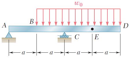
24 Sample Problem Given: a simply supported beam ith fleural rigidity EI is subjected to a uniformly distributed load ith density, on its central portion as shon Find: the euations of deflection and slope, and their maimum values ( ma, θ ma ). D E a a a a 4
25 Solution Thanks to symmetry, it is sufficient to consider only the left half M1( 1 ) a1 (0 1 a) M ( ) a ( a) ( a a) EI 1 a1 EI a ( a) a 1 D E a a a a a 5
26 a EI EI 1 a1 a EI D1 6 EI a ( a) a EI ( a) 6 a 4 EI ( a) D Due to symmetry: a 0 a 6 onstraint condition: D1 0 ontinuity conditions: a a, D D
27 Euations of deflection and slope: a 1 (11a 1 ) 6EI [ a ( a) 11a ] 6EI a 1 (11a 1 1 ) 6EI 4 [ 4a ( a) 44a 4EI Maimum deflection and slope: 0 a 0 ] a 1 1 a a a a 11a 19a ma 1 10, ma a 6EI 8EI 4 7
28 Deflection and Slope by Superposition Superposition of Loads: Deformation of beams subjected to combinations of loads may be obtained as the linear combination of the deformations due to individual loads. - eam material obeys linearly elastic Hooke s la. - No interactions eist among deformations induced by individual loads. - Procedure is facilitated by tables of solutions for common types of loadings and supports. 8
29 Sample Problem Using method of superposition to find the deflection at section and the slopes at sections and. m P l l 9
30 Solution: Superpose the deformations due to the uniformly distributed load (), the concentrated load (P) and the concentrated moment (m). m P P l l 4 5l Pl ml 84EI 48EI 16EI l Pl ml 4EI 16EI EI l Pl ml 4EI 16EI 6EI m 0
31 Sample Problem Find the deflections at sections and D. a D a a 1
32 Solution D a a a a D a a ( a) 5a 0, D 84EI 4EI
33 Sample Problem Find the deflection at section and the slope at section. l / l /
34 Solution l / l / / l l 4EI 5 l 84EI 4 / / 0 l 4EI 4
35 Sample Problem Given θ = 0, determine the relationship beteen m and P. a P a m 5
36 Solution: P m P m a a a a a Pa ma EI EI 0 m Pa 4 6
37 Deflection and Slope by Superposition Superposition of Rigidized Structures: pplicable to multi-span beams The total deflection of a multi-span beam under a given loading condition can be determined by superposing several beams corresponding to rigidizing all but one span of the beam, under the eactly same loading condition as the original beam. 7
38 Sample Problem Find the deflection at section of the simply supported overhanging beam shon. P Solution Deflection at due to L a rigidization of portion Rigidization EI = P c1 c1 Pa EI Pa EI 8
39 Deflection at due to rigidization of portion P P Pa Rigidization EI= PaL c a a EI Total deflection and slope at : c c1 c Pa a L Pa PaL a EI EI EI pal EI c c 1c Pa PaL Pa a L EI EI EI 9
40 Superposition of Loads & Rigidized Structures Given = 0, determine the relationship beteen P and. a a a P D 40
41 Solution: P P a a a D a a a D a a a D 4 5 ( a) Pa( a) 84EI 16EI 5 P a 6 0 P Pa a a a D 41
42 Sample Problem Using the method of superposition find the deflection and slope at section of the beam shon. a a a a 4
43 Solution: a a a Rigidizing a a a ( a) a EI 16EI 1EI 4 a a 1EI Rigidizing 4 a a, 6EI 8EI Total: a a a, a a a 1EI 6EI 4EI 1EI 8EI 4EI 4
44 Sample Problem stepped cantilever, as shon, is subjected to a concentrated load F at its free end. Find the deflection at the free end. F EI EI l/ l/ 44
45 Solution Rigidizing section makes a cantilever subjected to a concentrated load at its free end. F EI EI l/ l/ Rigidizing section makes the hole beam a cantilever. 1 θ 1 F 1 l 1 Pl 16EI l F Fl/ 45
46 Sample Problem Find the deflections at sections and D of the beam shon belo. a D a a a 46
47 Solution Rigidizing D 0, D Rigidizing a( a) 48EI ( a) a( a) 14a 8EI EI EI 4 7a EI 4 4 a a a D D a a a a D Total: 14 7 ( ) 8 a, D a a a a EI EI 48EI EI
48 Sample Problem For the structure composed of a beam and a frame shon, find the deflection at the center of the beam. Solution The deflection at section E is associated ith the folloing deformations: ending of beam itself. ending of ompression and bending of D l/ E F l/ EI l EI EI E l D Rigidize the frame (+D) E1 Fl 48EI E F 48
49 Rigidize + D F 1 1 ( ) l Fl E 1 EI 1EI 1 F/ Rigidize + 1 ( E Fl E (Deflection at due to the compression of D) ) F/ Fl/ F ( ll ) l l EI Fl EI D (Deflection at due to the bending of D) 49
50 1 Fl Fl ( ) E E EI Deflection at section E via superposition: Fl Fl E E1 E E EI E 17Fl Fl 48EI 4E 50

51 More Eamples 51

52 More Eamples 5


53 More Eamples 100 kn P 5
54 Singular / Discontinuity Functions f n ( ) a n ( 0 a) n a a f 0 () f 1 () f () n = 0 n = 1 n = a (a) a (b) a (c) 54
55 n a n d a n n n a n n a d d n n alculus of Singular Functions 55 a a a a f n n n 0 ) ( ) (
56 Euations of Shearing Forces & ending Moments M e F D E a 1 a a F l F FS F 0 F a a 0 1 F F a a M F 0 M a F a a 0 1 F M e a1 F a a e 1 56
57 oundary onditions Denote the shearing force and bending moment at the left boundary as F S0 and M 0 Generalized euation of shearing forces F ( ) F F a a s 0 1 S0 Generalized euation of bending moment M ( ) M F M a F a a S0 e 1 57
58 Deflection and Slope by Singular Functions EI M() M ( ) M F M a F a a S0 e 1 F F EI M M a a a 6 S0 1 0 e 1 1 M F M F EI a a a S0 e EI, EI
59 oundary Values F S0, M 0, 0 and 0 denote the boundary values of shearing force, bending moment, deflection and slope M F F S0 = F, M 0 = M 0 = 0, 0 = 0 F F S0 = F, M 0 = 0 0 0, 0 = 0 F S0 = 0, M 0 = 0 0 0, 0 0 (a) Fied support (b) Hinged support (c) Free end 59
60 Sample Problem Find the deflection at section and the slopes at sections and for the simply supported beam shon. l/ l Solution 1. Euations of deflection and slope FS0 l EI EI0 M 0!!! M0 FS0 l EI EI0 EI0!! 4! 4!
61 Determine boundary values FS0 F l, M 0 0, Determine 0 from the boundary condition at the movable hinged support : 4 l l 4 l l 0 EI l EI0l l EI l l l EI EI l l 4 l 4 61
62 . The Slopes and and the deflection EI l 18 l l EI l 18 l 0 18EI l l 4 l 1 1 7l l ( ) EI EI 4 4 l 1 5l l ( ) EI EI 6
63 Moment-rea Theorems Geometric properties of the elastic curve can be used to determine deflection and slope. onsider a beam subjected to arbitrary loading, D D d d y M M d d d EI EI D D M d EI First Moment-rea Theorem: D d area under (M/EI) diagram beteen and D. 6
64 Moment-rea Theorems Tangents to the elastic curve at P and P intercept a segment of length dt on the vertical through. M dt 1d 1 d EI D M td 1 d = tangential deviation of EI ith respect to D Second Moment-rea Theorem: The tangential deviation of ith respect to D is eual to the first moment ith respect to a vertical ais through of the area under the (M/EI) diagram beteen and D. 64

65 pplication to antilevers & eams under Symmetric Loading antilever beam - Select tangent at as the reference. θ D y D 0, y 0 D t D Simply supported, symmetrically loaded beam - select tangent at as the reference. θ 0, y y D D y y y t y y t D D ma 65
66 ending Moment Diagrams by Parts Determination of the change of slope and the tangential deviation is simplified if the effect of each load is evaluated separately. onstruct a separate (M/EI) diagram for each load. - The change of slope, θ D/, is obtained by adding the areas under the diagrams. - The tangential deviation, t D/ is obtained by adding the first moments of the areas ith respect to a vertical ais through D. ending moment diagram constructed from individual loads is said to be dran by parts. 66
67 Sample Problem SOLUTION: Determine the reactions at supports. For the prismatic beam shon, determine the deflection and slope at E. onstruct shear, bending moment and (M/EI) diagrams. Taking the tangent at as the reference, evaluate the slope and tangential deviations at E. 67
68 SOLUTION: Determine the reactions at supports. R R D a onstruct shear, bending moment and (M/EI) diagrams. 1 a EI L 1 a EI a L 4EI a a 6EI 68
69 Slope at E: E E E a L 1 4EI a E L a 1EI a 6EI Deflection at E: y t t t E E D E D y E a L 8EI a L a L 1 a a L a L a a L 4EI 16EI 8EI 16EI 69

70 pplication to eams under Unsymmetric Loadings Define reference tangent at support. Evaluate θ by determining the tangential deviation at ith respect to. t L The slope at other points is found ith respect to reference tangent. D D The deflection at D is found from the tangential deviation at D. FE FE t L L y FD FE DE t t L D D t 70
 diagram eual to -θ.")
71 Maimum Deflection Maimum deflection occurs at point K here the tangent is horizontal. t L K 0 K K Point K may be determined by measuring an area under the (M/EI) diagram eual to -θ. Obtain ma by computing the first moment ith respect to the vertical ais through of the area beteen and K. 71
72 Stiffness ondition ma [] θ ma [θ] W ma : Maimum deflection θ ma : Maimum slope [], [θ]: Maimum alloable deflection and slope Stiffness calculation include: - Stiffness check - Rational design of cross-sections - Find the maimum alloable loads 7
73 Ways to Increase Fleural Rigidity Deformation of beams under bending is influenced by not only beam supports and loading condition, but also beam material, cross-section size and shape, and beam span. - Increase EI - Decrease beam span / increase supports - Improve loading - Rational design of cross-sections 7
74 Sample Problem Given: l = 8 m, I z = 70 cm 4, W z = 7 cm, [] = l/500, E = 00 Gpa, [σ] = 100 Mpa. Find: 1. the maimum alloable load from the stiffness condition;. Strength check. I0a P z l l 74
75 Solution Pl l ma [ ] 48EI EI P 7.11kN 500l [ P] 7.11 kn M Pl ma ma 60 MPa [ ] Wz 4Wz The strength condition is satisfied. 75
76 ending Strain Energy Strain energy density: u 1 E E M Total strain energy calculated from density M y U dv dv E EI L L M M y d d EI EI 0 0 Total strain energy calculated from ork done by bending moment.r.t. rotation 1 M, d d dθ EI Md EI 1 M d L M ( ) EI 0 EI du Md U d d Neutral Surface o 1 a 1 dθ ρ o b d 76
77 ontents The Elastic urve, Deflection & Slope ( 挠曲线 挠度和转角 ) Differential Euation of the Elastic urve( 挠曲线微分方程 ) Deflection & Slope by Integration( 积分法求挠度和转角 ) oundary onditions( 边界条件 ) Symmetry onditions( 对称性条件 ) ontinuity onditions( 连续性条件 ) Direct Integration from Distributed Loads( 直接由分布荷载积分求挠度和转角 ) Direct Integration from Transverse Loads( 直接由剪力积分求挠度和转角 ) Deformations in a Transverse ross Section( 梁横截面内的变形 ) urvature Shortening( 梁由于弯曲造成的轴向位移 ) 77
78 ontents Deflection & Slope by Superposition( 叠加法求挠度和转角 ) Superposition of Loads( 荷载叠加法 ) Superposition of Rigidized Structures( 刚化叠加法 ) ombined Superposition( 荷载和变形组合叠加法 ) Deflection & Slope by Singular Functions( 奇异函数法求挠度和转角 ) Deflection & Slope by Moment-rea Theorems( 图乘法求挠度和转角 ) Stiffness ondition( 刚度条件 ) Ways to Increase Fleural Rigidity( 梁的刚度优化设计 ) ending Strain Energy( 弯曲应变能 ) 78
Bending Internal Forces.
 ending Internal orces mi@seu.edu.cn Contents Introduction( 弯曲变形简介 ) The orms of Internal orces in eams( 梁中内力的形式 ) Symmetric ending( 对称弯曲 ) Types of eams( 静定梁的分类 ) Types of Supports and Reactions( 梁的支撑种类及相应的支座反力形式
Lecture English Term Definition Chinese: Public
 Lecture English Term Definition Chinese: Public A Convert Change between two forms of measurements 变换 A Equilateral Triangle Triangle with equal sides and angles A FPS Units The American system of measurement.
OUTLINE. CHAPTER 7: Flexural Members. Types of beams. Types of loads. Concentrated load Distributed load. Moment
 OUTLINE CHTER 7: Fleural embers -Tpes of beams, loads and reations -Shear fores and bending moments -Shear fore and bending - -The fleure formula -The elasti urve -Slope and defletion b diret integration
Elastic Cylinders Subjected to End Loadings.
 Elastic Clinders Subjected to End Loadings mi@seu.edu.cn Outline Elastic Clinders with End Loading ( 端部受载柱体 ) Etension of Clinders ( 拉伸 ) Torsion of Clinders ( 扭转 ) Stress Function Formulation ( 应力函数体系
CHAPTER 7 DEFLECTIONS OF BEAMS
 CHPTER 7 DEFLECTIONS OF EMS OJECTIVES Determine the deflection and slope at specific points on beams and shafts, using various analytical methods including: o o o The integration method The use of discontinuity
7.4 The Elementary Beam Theory
 7.4 The Elementary Beam Theory In this section, problems involving long and slender beams are addressed. s with pressure vessels, the geometry of the beam, and the specific type of loading which will be
3. BEAMS: STRAIN, STRESS, DEFLECTIONS
 3. BEAMS: STRAIN, STRESS, DEFLECTIONS The beam, or flexural member, is frequently encountered in structures and machines, and its elementary stress analysis constitutes one of the more interesting facets
Torsion.
 Torsion mi@seu.edu.cn Contents Introduction to Torsion( 扭转简介 ) Examples of Torsion Shafts( 扭转轴示例 ) Sign Convention of Torque( 扭矩符号规则 ) Torque Diagram( 扭矩图 ) Power & Torque( 功率与扭矩 ) Internal Torque & Stress
REVIEW FOR EXAM II. Dr. Ibrahim A. Assakkaf SPRING 2002
 REVIEW FOR EXM II. J. Clark School of Engineering Department of Civil and Environmental Engineering b Dr. Ibrahim. ssakkaf SPRING 00 ENES 0 Mechanics of Materials Department of Civil and Environmental
BEAM A horizontal or inclined structural member that is designed to resist forces acting to its axis is called a beam
 BEM horizontal or inclined structural member that is designed to resist forces acting to its axis is called a beam INTERNL FORCES IN BEM Whether or not a beam will break, depend on the internal resistances
Chapter 4 Deflection and Stiffness
 Chapter 4 Deflection and Stiffness Asst. Prof. Dr. Supakit Rooppakhun Chapter Outline Deflection and Stiffness 4-1 Spring Rates 4-2 Tension, Compression, and Torsion 4-3 Deflection Due to Bending 4-4 Beam
[8] Bending and Shear Loading of Beams
![[8] Bending and Shear Loading of Beams](/thumbs/92/110949676.jpg "[8] Bending and Shear Loading of Beams") [8] Bending and Shear Loading of Beams Page 1 of 28 [8] Bending and Shear Loading of Beams [8.1] Bending of Beams (will not be covered in class) [8.2] Bending Strain and Stress [8.3] Shear in Straight
[8] Bending and Shear Loading of Beams Page 1 of 28 [8] Bending and Shear Loading of Beams [8.1] Bending of Beams (will not be covered in class) [8.2] Bending Strain and Stress [8.3] Shear in Straight
PURE BENDING. If a simply supported beam carries two point loads of 10 kn as shown in the following figure, pure bending occurs at segment BC.
 BENDING STRESS The effect of a bending moment applied to a cross-section of a beam is to induce a state of stress across that section. These stresses are known as bending stresses and they act normally
BEAM DEFLECTION THE ELASTIC CURVE
 BEAM DEFLECTION Samantha Ramirez THE ELASTIC CURVE The deflection diagram of the longitudinal axis that passes through the centroid of each cross-sectional area of a beam. Supports that apply a moment
Problem d d d B C E D. 0.8d. Additional lecturebook examples 29 ME 323
 Problem 9.1 Two beam segments, AC and CD, are connected together at C by a frictionless pin. Segment CD is cantilevered from a rigid support at D, and segment AC has a roller support at A. a) Determine
Moment Area Method. 1) Read
 Read") Moment Area Method Lesson Objectives: 1) Identify the formulation and sign conventions associated with the Moment Area method. 2) Derive the Moment Area method theorems using mechanics and mathematics.
Moment Area Method Lesson Objectives: 1) Identify the formulation and sign conventions associated with the Moment Area method. 2) Derive the Moment Area method theorems using mechanics and mathematics.
Axial Loading Concept of Stress & Strain.
 Axial Loading Concept of Stress & Strain mi@seu.edu.cn Contents Introduction( 拉压变形简介 ) Diagram of Axial Forces( 轴力图 ) Concept of Stresses( 应力的概念 ) General Stress State of a Point( 点的一般应力状态 ) Stresses Acting
Mechanics in Energy Resources Engineering - Chapter 5 Stresses in Beams (Basic topics)
") Week 7, 14 March Mechanics in Energy Resources Engineering - Chapter 5 Stresses in Beams (Basic topics) Ki-Bok Min, PhD Assistant Professor Energy Resources Engineering i Seoul National University Shear
Week 7, 14 March Mechanics in Energy Resources Engineering - Chapter 5 Stresses in Beams (Basic topics) Ki-Bok Min, PhD Assistant Professor Energy Resources Engineering i Seoul National University Shear
Assumptions: beam is initially straight, is elastically deformed by the loads, such that the slope and deflection of the elastic curve are
 *12.4 SLOPE & DISPLACEMENT BY THE MOMENT-AREA METHOD Assumptions: beam is initially straight, is elastically deformed by the loads, such that the slope and deflection of the elastic curve are very small,
Review Lecture. AE1108-II: Aerospace Mechanics of Materials. Dr. Calvin Rans Dr. Sofia Teixeira De Freitas
 Review Lecture AE1108-II: Aerospace Mechanics of Materials Dr. Calvin Rans Dr. Sofia Teixeira De Freitas Aerospace Structures & Materials Faculty of Aerospace Engineering Analysis of an Engineering System
MECHANICS OF MATERIALS
 CHAPTER 2 MECHANICS OF MATERIALS Ferdinand P. Beer E. Russell Johnston, Jr. John T. DeWolf David F. Mazurek Lecture Notes: J. Walt Oler Texas Tech University Stress and Strain Axial Loading 2.1 An Introduction
Two-Dimensional Formulation.
 Two-Dimensional Formulation mi@seu.edu.cn Outline Introduction( 概论 ) Two vs. Three-Dimensional Problems Plane Strain( 平面应变 ) Plane Stress( 平面应力 ) Boundar Conditions( 边界条件 ) Correspondence between Plane
Consider an elastic spring as shown in the Fig.2.4. When the spring is slowly
 .3 Strain Energy Consider an elastic spring as shown in the Fig..4. When the spring is slowly pulled, it deflects by a small amount u 1. When the load is removed from the spring, it goes back to the original
The bending moment diagrams for each span due to applied uniformly distributed and concentrated load are shown in Fig.12.4b.
 From inspection, it is assumed that the support moments at is zero and support moment at, 15 kn.m (negative because it causes compression at bottom at ) needs to be evaluated. pplying three- Hence, only
STRESS STRAIN AND DEFORMATION OF SOLIDS, STATES OF STRESS
 1 UNIT I STRESS STRAIN AND DEFORMATION OF SOLIDS, STATES OF STRESS 1. Define: Stress When an external force acts on a body, it undergoes deformation. At the same time the body resists deformation. The
STRENGTH OF MATERIALS-I. Unit-1. Simple stresses and strains
 STRENGTH OF MATERIALS-I Unit-1 Simple stresses and strains 1. What is the Principle of surveying 2. Define Magnetic, True & Arbitrary Meridians. 3. Mention different types of chains 4. Differentiate between
CHAPTER THREE SYMMETRIC BENDING OF CIRCLE PLATES
 CHAPTER THREE SYMMETRIC BENDING OF CIRCLE PLATES * Governing equations in beam and plate bending ** Solution by superposition 1.1 From Beam Bending to Plate Bending 1.2 Governing Equations For Symmetric
Beams on elastic foundation
 Beams on elastic foundation I Basic concepts The beam lies on elastic foundation when under the applied eternal loads, the reaction forces of the foundation are proportional at every point to the deflection
6. Bending CHAPTER OBJECTIVES
 CHAPTER OBJECTIVES Determine stress in members caused by bending Discuss how to establish shear and moment diagrams for a beam or shaft Determine largest shear and moment in a member, and specify where
structural analysis Excessive beam deflection can be seen as a mode of failure.
 Structure Analysis I Chapter 8 Deflections Introduction Calculation of deflections is an important part of structural analysis Excessive beam deflection can be seen as a mode of failure. Extensive glass
Comb Resonator Design (2)
") Lecture 6: Comb Resonator Design () -Intro. to Mechanics of Materials Sh School of felectrical ti lengineering i and dcomputer Science, Si Seoul National University Nano/Micro Systems & Controls Laboratory
Lecture 6: Comb Resonator Design () -Intro. to Mechanics of Materials Sh School of felectrical ti lengineering i and dcomputer Science, Si Seoul National University Nano/Micro Systems & Controls Laboratory
Finite Element Analysis Prof. Dr. B. N. Rao Department of Civil Engineering Indian Institute of Technology, Madras. Module - 01 Lecture - 11
 Finite Element Analysis Prof. Dr. B. N. Rao Department of Civil Engineering Indian Institute of Technology, Madras Module - 01 Lecture - 11 Last class, what we did is, we looked at a method called superposition
UNIT 1 STRESS STRAIN AND DEFORMATION OF SOLIDS, STATES OF STRESS 1. Define stress. When an external force acts on a body, it undergoes deformation.
 UNIT 1 STRESS STRAIN AND DEFORMATION OF SOLIDS, STATES OF STRESS 1. Define stress. When an external force acts on a body, it undergoes deformation. At the same time the body resists deformation. The magnitude
Problem 1: Calculating deflection by integration uniform load. Problem 2: Calculating deflection by integration - triangular load pattern
 Problem 1: Calculating deflection by integration uniform load Problem 2: Calculating deflection by integration - triangular load pattern Problem 3: Deflections - by differential equations, concentrated
4.5 The framework element stiffness matrix
 45 The framework element stiffness matri Consider a 1 degree-of-freedom element that is straight prismatic and symmetric about both principal cross-sectional aes For such a section the shear center coincides
Moment Distribution Method
 Moment Distribution Method Lesson Objectives: 1) Identify the formulation and sign conventions associated with the Moment Distribution Method. 2) Derive the Moment Distribution Method equations using mechanics
Outline. Organization. Stresses in Beams
 Stresses in Beams B the end of this lesson, ou should be able to: Calculate the maimum stress in a beam undergoing a bending moment 1 Outline Curvature Normal Strain Normal Stress Neutral is Moment of
Advanced Structural Analysis EGF Section Properties and Bending
 Advanced Structural Analysis EGF316 3. Section Properties and Bending 3.1 Loads in beams When we analyse beams, we need to consider various types of loads acting on them, for example, axial forces, shear
March 24, Chapter 4. Deflection and Stiffness. Dr. Mohammad Suliman Abuhaiba, PE
 Chapter 4 Deflection and Stiffness 1 2 Chapter Outline Spring Rates Tension, Compression, and Torsion Deflection Due to Bending Beam Deflection Methods Beam Deflections by Superposition Strain Energy Castigliano
KINGS COLLEGE OF ENGINEERING DEPARTMENT OF MECHANICAL ENGINEERING QUESTION BANK. Subject code/name: ME2254/STRENGTH OF MATERIALS Year/Sem:II / IV
 KINGS COLLEGE OF ENGINEERING DEPARTMENT OF MECHANICAL ENGINEERING QUESTION BANK Subject code/name: ME2254/STRENGTH OF MATERIALS Year/Sem:II / IV UNIT I STRESS, STRAIN DEFORMATION OF SOLIDS PART A (2 MARKS)
4. BEAMS: CURVED, COMPOSITE, UNSYMMETRICAL
 4. BEMS: CURVED, COMPOSITE, UNSYMMETRICL Discussions of beams in bending are usually limited to beams with at least one longitudinal plane of symmetry with the load applied in the plane of symmetry or
CHAPTER OBJECTIVES Use various methods to determine the deflection and slope at specific pts on beams and shafts: 2. Discontinuity functions
 1. Deflections of Beams and Shafts CHAPTER OBJECTIVES Use various methods to determine the deflection and slope at specific pts on beams and shafts: 1. Integration method. Discontinuity functions 3. Method
Column Buckling.
 Column Buckling mi@seu.edu.cn Contents Stability and Buckling( 稳定性与失稳 ) Examples of Columns( 压杆应用示例 ) Conventional Design of Columns( 压杆的常规设计方法 ) Euler s Formula for in-ended Columns( 端部铰接压杆欧拉公式 ) Buckling
DESIGN OF BEAMS AND SHAFTS
 DESIGN OF EAMS AND SHAFTS! asis for eam Design! Stress Variations Throughout a Prismatic eam! Design of pristmatic beams! Steel beams! Wooden beams! Design of Shaft! ombined bending! Torsion 1 asis for
QUESTION BANK SEMESTER: III SUBJECT NAME: MECHANICS OF SOLIDS
 QUESTION BANK SEMESTER: III SUBJECT NAME: MECHANICS OF SOLIDS UNIT 1- STRESS AND STRAIN PART A (2 Marks) 1. Define longitudinal strain and lateral strain. 2. State Hooke s law. 3. Define modular ratio,
Shear Force V: Positive shear tends to rotate the segment clockwise.
 INTERNL FORCES IN EM efore a structural element can be designed, it is necessary to determine the internal forces that act within the element. The internal forces for a beam section will consist of a shear
SERVICEABILITY OF BEAMS AND ONE-WAY SLABS
 CHAPTER REINFORCED CONCRETE Reinforced Concrete Design A Fundamental Approach - Fifth Edition Fifth Edition SERVICEABILITY OF BEAMS AND ONE-WAY SLABS A. J. Clark School of Engineering Department of Civil
14. *14.8 CASTIGLIANO S THEOREM
 *14.8 CASTIGLIANO S THEOREM Consider a body of arbitrary shape subjected to a series of n forces P 1, P 2, P n. Since external work done by forces is equal to internal strain energy stored in body, by
 UNIT III DEFLECTION OF BEAMS 1. What are the methods for finding out the slope and deflection at a section? The important methods used for finding out the slope and deflection at a section in a loaded
Comb resonator design (2)
") Lecture 6: Comb resonator design () -Intro Intro. to Mechanics of Materials School of Electrical l Engineering i and Computer Science, Seoul National University Nano/Micro Systems & Controls Laboratory
Lecture 6: Comb resonator design () -Intro Intro. to Mechanics of Materials School of Electrical l Engineering i and Computer Science, Seoul National University Nano/Micro Systems & Controls Laboratory
Module 3. Analysis of Statically Indeterminate Structures by the Displacement Method
 odule 3 Analysis of Statically Indeterminate Structures by the Displacement ethod Lesson 21 The oment- Distribution ethod: rames with Sidesway Instructional Objectives After reading this chapter the student
Theory of Elasticity. Chapter 9 Two-Dimensional Solution
 Theo of Elsticit 9 Two-Dimensionl Solution Content Intoduction Mthemticl Peliminies Stess nd Euiliium Displcements nd Stins Mteil Behvio- Line Elstic Solids Fomultion nd Solution Sttegies Two-Dimensionl
Chapter 7: Internal Forces
 Chapter 7: Internal Forces Chapter Objectives To show how to use the method of sections for determining the internal loadings in a member. To generalize this procedure by formulating equations that can
MECE 3321: Mechanics of Solids Chapter 6
 MECE 3321: Mechanics of Solids Chapter 6 Samantha Ramirez Beams Beams are long straight members that carry loads perpendicular to their longitudinal axis Beams are classified by the way they are supported
CHAPTER 4: BENDING OF BEAMS
 (74) CHAPTER 4: BENDING OF BEAMS This chapter will be devoted to the analysis of prismatic members subjected to equal and opposite couples M and M' acting in the same longitudinal plane. Such members are
MECHANICS OF MATERIALS Sample Problem 4.2
 Sample Problem 4. SOLUTON: Based on the cross section geometry, calculate the location of the section centroid and moment of inertia. ya ( + Y Ad ) A A cast-iron machine part is acted upon by a kn-m couple.
Example 3.7 Consider the undeformed configuration of a solid as shown in Figure 3.60.
 162 3. The linear 3-D elasticity mathematical model The 3-D elasticity model is of great importance, since it is our highest order hierarchical model assuming linear elastic behavior. Therefore, it provides
PES Institute of Technology
 PES Institute of Technology Bangalore south campus, Bangalore-5460100 Department of Mechanical Engineering Faculty name : Madhu M Date: 29/06/2012 SEM : 3 rd A SEC Subject : MECHANICS OF MATERIALS Subject
Mechanics of Materials II. Chapter III. A review of the fundamental formulation of stress, strain, and deflection
 Mechanics of Materials II Chapter III A review of the fundamental formulation of stress, strain, and deflection Outline Introduction Assumtions and limitations Axial loading Torsion of circular shafts
MECHANICS OF MATERIALS. Analysis of Beams for Bending
 MECHANICS OF MATERIALS Analysis of Beams for Bending By NUR FARHAYU ARIFFIN Faculty of Civil Engineering & Earth Resources Chapter Description Expected Outcomes Define the elastic deformation of an axially
Chapter 5 Structural Elements: The truss & beam elements
 Institute of Structural Engineering Page 1 Chapter 5 Structural Elements: The truss & beam elements Institute of Structural Engineering Page 2 Chapter Goals Learn how to formulate the Finite Element Equations
QUESTION BANK ENGINEERS ACADEMY. Hinge E F A D. Theory of Structures Determinacy Indeterminacy 1
 Theory of Structures eterminacy Indeterminacy 1 QUSTION NK 1. The static indeterminacy of the structure shown below (a) (b) 6 (c) 9 (d) 12 2. etermine the degree of freedom of the following frame (a) 1
Chapter 2: Deflections of Structures
 Chapter 2: Deflections of Structures Fig. 4.1. (Fig. 2.1.) ASTU, Dept. of C Eng., Prepared by: Melkamu E. Page 1 (2.1) (4.1) (2.2) Fig.4.2 Fig.2.2 ASTU, Dept. of C Eng., Prepared by: Melkamu E. Page 2
LECTURE 13 Strength of a Bar in Pure Bending
 V. DEMENKO MECHNCS OF MTERLS 015 1 LECTURE 13 Strength of a Bar in Pure Bending Bending is a tpe of loading under which bending moments and also shear forces occur at cross sections of a rod. f the bending
D : SOLID MECHANICS. Q. 1 Q. 9 carry one mark each. Q.1 Find the force (in kn) in the member BH of the truss shown.
 in the member BH of the truss shown.") D : SOLID MECHANICS Q. 1 Q. 9 carry one mark each. Q.1 Find the force (in kn) in the member BH of the truss shown. Q.2 Consider the forces of magnitude F acting on the sides of the regular hexagon having
D : SOLID MECHANICS Q. 1 Q. 9 carry one mark each. Q.1 Find the force (in kn) in the member BH of the truss shown. Q.2 Consider the forces of magnitude F acting on the sides of the regular hexagon having
Lecture Slides. Chapter 4. Deflection and Stiffness. The McGraw-Hill Companies 2012
 Lecture Slides Chapter 4 Deflection and Stiffness The McGraw-Hill Companies 2012 Chapter Outline Force vs Deflection Elasticity property of a material that enables it to regain its original configuration
MTE 119 STATICS LECTURE MATERIALS FINAL REVIEW PAGE NAME & ID DATE. Example Problem F.1: (Beer & Johnston Example 9-11)
") Eample Problem F.: (Beer & Johnston Eample 9-) Determine the mass moment of inertia with respect to: (a) its longitudinal ais (-ais) (b) the y-ais SOLUTION: a) Mass moment of inertia about the -ais: Step
Eample Problem F.: (Beer & Johnston Eample 9-) Determine the mass moment of inertia with respect to: (a) its longitudinal ais (-ais) (b) the y-ais SOLUTION: a) Mass moment of inertia about the -ais: Step
Deflection of Beams. Equation of the Elastic Curve. Boundary Conditions
 Deflection of Beams Equation of the Elastic Curve The governing second order differential equation for the elastic curve of a beam deflection is EI d d = where EI is the fleural rigidit, is the bending
QUESTION BANK DEPARTMENT: CIVIL SEMESTER: III SUBJECT CODE: CE2201 SUBJECT NAME: MECHANICS OF SOLIDS UNIT 1- STRESS AND STRAIN PART A
 DEPARTMENT: CIVIL SUBJECT CODE: CE2201 QUESTION BANK SEMESTER: III SUBJECT NAME: MECHANICS OF SOLIDS UNIT 1- STRESS AND STRAIN PART A (2 Marks) 1. Define longitudinal strain and lateral strain. 2. State
FIXED BEAMS IN BENDING
 FIXED BEAMS IN BENDING INTRODUCTION Fixed or built-in beams are commonly used in building construction because they possess high rigidity in comparison to simply supported beams. When a simply supported
CHAPTER -6- BENDING Part -1-
 Ishik University / Sulaimani Civil Engineering Department Mechanics of Materials CE 211 CHAPTER -6- BENDING Part -1-1 CHAPTER -6- Bending Outlines of this chapter: 6.1. Chapter Objectives 6.2. Shear and
Sub. Code:
 Important Instructions to examiners: ) The answers should be examined by key words and not as word-to-word as given in the model answer scheme. ) The model answer and the answer written by candidate may
Mechanics of Materials MENG 270 Fall 2003 Exam 3 Time allowed: 90min. Q.1(a) Q.1 (b) Q.2 Q.3 Q.4 Total
 Q.1 (b) Q.2 Q.3 Q.4 Total") Mechanics of Materials MENG 70 Fall 00 Eam Time allowed: 90min Name. Computer No. Q.(a) Q. (b) Q. Q. Q.4 Total Problem No. (a) [5Points] An air vessel is 500 mm average diameter and 0 mm thickness, the
Mechanics of Materials MENG 70 Fall 00 Eam Time allowed: 90min Name. Computer No. Q.(a) Q. (b) Q. Q. Q.4 Total Problem No. (a) [5Points] An air vessel is 500 mm average diameter and 0 mm thickness, the
Stresses in Curved Beam
 Stresses in Curved Beam Consider a curved beam subjected to bending moment M b as shown in the figure. The distribution of stress in curved flexural member is determined by using the following assumptions:
Types of Structures & Loads
 Structure Analysis I Chapter 4 1 Types of Structures & Loads 1Chapter Chapter 4 Internal lloading Developed in Structural Members Internal loading at a specified Point In General The loading for coplanar
- Beams are structural member supporting lateral loadings, i.e., these applied perpendicular to the axes.
 4. Shear and Moment functions - Beams are structural member supporting lateral loadings, i.e., these applied perpendicular to the aes. - The design of such members requires a detailed knowledge of the
If the number of unknown reaction components are equal to the number of equations, the structure is known as statically determinate.
 1 of 6 EQUILIBRIUM OF A RIGID BODY AND ANALYSIS OF ETRUCTURAS II 9.1 reactions in supports and joints of a two-dimensional structure and statically indeterminate reactions: Statically indeterminate structures
EMA 3702 Mechanics & Materials Science (Mechanics of Materials) Chapter 5 Beams for Bending
 Chapter 5 Beams for Bending") MA 3702 Mechanics & Materials Science (Mechanics of Materials) Chapter 5 Beams for Bending Introduction esign of beams for mechanical or civil/structural applications Transverse loading in most cases for
MA 3702 Mechanics & Materials Science (Mechanics of Materials) Chapter 5 Beams for Bending Introduction esign of beams for mechanical or civil/structural applications Transverse loading in most cases for
PROBLEM #1.1 (4 + 4 points, no partial credit)
") PROBLEM #1.1 ( + points, no partial credit A thermal switch consists of a copper bar which under elevation of temperature closes a gap and closes an electrical circuit. The copper bar possesses a length
PROBLEM #1.1 ( + points, no partial credit A thermal switch consists of a copper bar which under elevation of temperature closes a gap and closes an electrical circuit. The copper bar possesses a length
1.571 Structural Analysis and Control Prof. Connor Section 3: Analysis of Cable Supported Structures
 .57 Structural Analysis and Control Prof. Connor Section 3: Analysis of Cale Supported Structures Many high performance structures include cales and cale systems. Analysis and design of cale systems is
Deflection of Flexural Members - Macaulay s Method 3rd Year Structural Engineering
 Deflection of Flexural Members - Macaulay s Method 3rd Year Structural Engineering 008/9 Dr. Colin Caprani 1 Contents 1. Introduction... 3 1.1 General... 3 1. Background... 4 1.3 Discontinuity Functions...
Deflection of Flexural Members - Macaulay s Method 3rd Year Structural Engineering
 Deflection of Flexural Members - Macaulay s Method 3rd Year Structural Engineering 009/10 Dr. Colin Caprani 1 Contents 1. Introduction... 4 1.1 General... 4 1. Background... 5 1.3 Discontinuity Functions...
CE6306 STRENGTH OF MATERIALS TWO MARK QUESTIONS WITH ANSWERS ACADEMIC YEAR
 CE6306 STRENGTH OF MATERIALS TWO MARK QUESTIONS WITH ANSWERS ACADEMIC YEAR 2014-2015 UNIT - 1 STRESS, STRAIN AND DEFORMATION OF SOLIDS PART- A 1. Define tensile stress and tensile strain. The stress induced
BEAMS: SHEAR AND MOMENT DIAGRAMS (FORMULA)
") LETURE Third Edition BEMS: SHER ND MOMENT DGRMS (FORMUL). J. lark School of Engineering Department of ivil and Environmental Engineering 1 hapter 5.1 5. b Dr. brahim. ssakkaf SPRNG 00 ENES 0 Mechanics
LETURE Third Edition BEMS: SHER ND MOMENT DGRMS (FORMUL). J. lark School of Engineering Department of ivil and Environmental Engineering 1 hapter 5.1 5. b Dr. brahim. ssakkaf SPRNG 00 ENES 0 Mechanics
Aircraft Structures Beams Torsion & Section Idealization
 Universit of Liège Aerospace & Mechanical Engineering Aircraft Structures Beams Torsion & Section Idealiation Ludovic Noels omputational & Multiscale Mechanics of Materials M3 http://www.ltas-cm3.ulg.ac.be/
Figure 2-1: Stresses under axisymmetric circular loading
 . Stresses in Pavements.1. Stresses in Fleible Pavements.1.1. Stresses in Homogeneous Mass Boussinesq formulated models for the stresses inside an elastic half-space due to a concentrated load applied
Lecture 15 Strain and stress in beams
 Spring, 2019 ME 323 Mechanics of Materials Lecture 15 Strain and stress in beams Reading assignment: 6.1 6.2 News: Instructor: Prof. Marcial Gonzalez Last modified: 1/6/19 9:42:38 PM Beam theory (@ ME
MECHANICS OF MATERIALS
 009 The McGraw-Hill Companies, nc. All rights reserved. Fifth S E CHAPTER 6 MECHANCS OF MATERALS Ferdinand P. Beer E. Russell Johnston, Jr. John T. DeWolf David F. Mazurek Lecture Notes: J. Walt Oler Texas
Module 3. Analysis of Statically Indeterminate Structures by the Displacement Method
 odule 3 Analysis of Statically Indeterminate Structures by the Displacement ethod Lesson 14 The Slope-Deflection ethod: An Introduction Introduction As pointed out earlier, there are two distinct methods
Shear Force and Bending Moment
 Shear Fore and Bending oent Shear Fore: is the algebrai su of the vertial fores ating to the left or right of a ut setion along the span of the bea Bending oent: is the algebrai su of the oent of the fores
Structural Analysis III Moment Distribution
 Structural Analysis III oment Distribution 2008/9 Dr. Colin Caprani 1 Contents 1. Introduction... 4 1.1 Overview... 4 1.2 The Basic Idea... 5 2. Development... 10 2.1 Carry-Over... 10 2.2 Fixed End oments...
Chapter 8 Supplement: Deflection in Beams Double Integration Method
 Chapter 8 Supplement: Deflection in Beams Double Integration Method 8.5 Beam Deflection Double Integration Method In this supplement, we describe the methods for determining the equation of the deflection
σ = Eα(T T C PROBLEM #1.1 (4 + 4 points, no partial credit)
") PROBLEM #1.1 (4 + 4 points, no partial credit A thermal switch consists of a copper bar which under elevation of temperature closes a gap and closes an electrical circuit. The copper bar possesses a length
PROBLEM #1.1 (4 + 4 points, no partial credit A thermal switch consists of a copper bar which under elevation of temperature closes a gap and closes an electrical circuit. The copper bar possesses a length
Lecture: P1_Wk4_L1 Cantilever Mechanics The Force Sensor. Ron Reifenberger Birck Nanotechnology Center Purdue University 2012
 Leture: Cantilever Mehanis The Fore Sensor Ron Reifenberger Birk Nanotehnology Center Purdue University 0 Defletion vs. z Week 4 Overview Fore Spetrosopy Piezos Cantilever Instrumentation Controller Calibration
ENG2000 Chapter 7 Beams. ENG2000: R.I. Hornsey Beam: 1
 ENG2000 Chapter 7 Beams ENG2000: R.I. Hornsey Beam: 1 Overview In this chapter, we consider the stresses and moments present in loaded beams shear stress and bending moment diagrams We will also look at
UNIT IV FLEXIBILTY AND STIFFNESS METHOD
 SIDDHARTH GROUP OF INSTITUTIONS :: PUTTUR Siddharth Nagar, Narayanavanam Road 517583 QUESTION BANK (DESCRIPTIVE) Subject with Code : SA-II (13A01505) Year & Sem: III-B.Tech & I-Sem Course & Branch: B.Tech
Beam Design and Deflections
 Beam Design and Deflections tation: a = name for width dimension A = name for area Areq d-adj = area required at allowable stress when shear is adjusted to include self weight Aweb = area of the web of
Chapter 5 Elastic Strain, Deflection, and Stability 1. Elastic Stress-Strain Relationship
 Chapter 5 Elastic Strain, Deflection, and Stability Elastic Stress-Strain Relationship A stress in the x-direction causes a strain in the x-direction by σ x also causes a strain in the y-direction & z-direction
Theory and Analysis of Structures
 7 Theory and nalysis of Structures J.Y. Richard iew National University of Singapore N.E. Shanmugam National University of Singapore 7. Fundamental Principles oundary Conditions oads and Reactions Principle
IVIL.COM, C. English - Arabic. Arrow Assume Assumption Available Average Axes Axial Axis
 Abrupt Action Accuracy Accurate Advantage Algebra Algebraic Algebraic equation English - Arabic Algebraic expression Algebraic sum Allow Allowable Ambiguous Analyze Analysis f sections Structural analysis