Graser User Conference Only
|
|
|
- Carmel Benson
- 5 years ago
- Views:
Transcription


1 PCB Power Delivery Design from DC to Mid-Frequency Foxconn Abby Chou


2 Company Introduction February 1974 Tucheng District 1.23 million Server Storage Mobile Phone Pad TV

3 Voltage Drop and Thermal Co-Simulation


4 Illustration for Voltage Drop Energy Energy
5 How to Calculate Resistance 40mil trace width for 1A current? R Copper = L ρ A = 1 L σ A Need to take cross-section area and length into consideration. 40mil? Length 1A R : Resistance (Ω) ρ : Resistivity (Ω*m) σ : Conductivity (S/m) L : Length (m) A : Cross-Section Area (m 2 ) Cross-Section

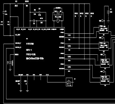
6 Analysis in PowerDC For the irregular shape, manual calculation by formula is difficult and simulation is necessary. VRM SINK

7 Voltage Drop Correlation Equivalent MB resistance matrix derived from PowerDC FB1 FB2 FB3 FB4 FB5 FB6 FB7 FB8 Measured 1.474V 1.480V 1.477V 1.483V 1.481V 1.488v 1.487V 1.493v Simulated 1.473V 1.475V 1.477V 1.480V 1.482V 1.485V 1.489V 1.493V


8 PCB Temperature HOT!! High Current Density High Temperature Rise PCB Burned


 Current (A)")
9 PCB Temperature Simulator PCB temperature become higher and more important due to the larger current. Copper Width : 1mm, Cross-Section : 0.067mm 2 Current : 1.1A, PCB Temperature Rise : 5 o C Copper Width (mm) Current (A) Cross-Section (mm 2 ) Cross-Section (mm 2 ) 9


10 PCB Temperature Distribution Foxconn in-house tool can calculate PCB temperature distribution by using copper width, cross-section and flowing current. (Ref. doc. : IPC-2221, IPC-2152) 2 ~ 3 variation due to the air-flow and heat transfer. In-House Simulator Infrared Ray Camera
 Total power:")

11 Temperature Simulation in PowerDC (1/2) Total power: 1400W Variation < 4
 Total power: 3900W")

12 Temperature Simulation in PowerDC (2/2) Total power: 3900W Simulation Measurement Variation < 5


13 Via Current Simulation in PowerDC (1/2) The connector via current can not over 10A for thermal concern. Current Vector & Density Plot Via Current Plot Over 10A! 7.7A 6.4A 6.5A 7.8A 11A


14 Via Current Simulation in PowerDC (2/2) Cut the shape to change path resistance for via current balancing purpose. Current Vector & Density Plot Via Current Plot Under 10A! 7.1A 6.1A 8.1A 8.8A 9.3A


15 PDN AC Analysis


16 Power Delivery Network VRM Bulk MLCC Plane Package Chip Impedance khz MHz GHz Freq.


17 Transient Simulation VR Model PDN extract by PowerSI Load

18 Transient Voltage Correlation Simulation Measurement Measurement Value Simulation Value Difference 1 st Voltage Spike 1.086V V 0.3mV

19 Measurement Fail Issue The min voltage fail to meet specification.

")
20 Transient Correlation - Original Using PowerSI to extract PDN model to get transient waveform. Max Voltage Simulation Results Measurement Results Min Voltage Simulation Measurement Min Voltage (V)


21 Failure Issue Analysis Simulation Measurement V1=L loop *di/dt V2=R loop * I V1 V2 It can be found that the parasitic loop inductance dominates most of the droop. Thus it is necessary to inspect the loop inductance of board file.
22 Impedance Analysis in PowerSI The original 22uF MLCC self-resonant frequency is 2.36MHz, but now it moves to 700kHz. MLCC self-resonant is around 700kHz.
23 Current Loop Analysis Original: Top Pwr2 Cap (Top) CPU 2.7mil 50mil VCCP GND Improvement: Change pwr2 to GND plane Gnd3 Bottom Top Pwr2 Cap (Top) CPU 2.7mil 2.7mil 50mil Gnd3 Bottom 2.7mil


24 Loop Inductance Analysis in OPI Original Improvement Top Layer For overall loop inductance, improvement case is better than original.

 80.32 54.44 Improvement V = 80.32 54.44 = 25.")
25 Measurement Original Layout After Modifying Layout CH1:VCCP CH1:VCCP CH2:Io CH2:Io Spec. = 70mV Original Layout Modified Layout Voltage Droop (mv) Improvement V = = mv


26 Summary Simulation tools can.. help designer to ensure design quality predict validation results and has good correlation verify designer s thought and find the best solution more..


27
EMC Considerations for DC Power Design
 EMC Considerations for DC Power Design Tzong-Lin Wu, Ph.D. Department of Electrical Engineering National Sun Yat-sen University Power Bus Noise below 5MHz 1 Power Bus Noise below 5MHz (Solution) Add Bulk
Power Integrity in System Design
 Power Integrity in System Design Design. Build. Ship. Service. CAE / Design Simulation Skipper Liang 5/20/2008 1 Agenda Introduction Power Integrity Concept DC Analysis for Power Integrity AC Analysis
Power Distribution Network Design for High-Speed Printed Circuit Boards
 Power Distribution Network Design for High-Speed Printed Circuit Boards Jun Fan NCR Corporation 1 Outline Overview of PDN design in multi-layer PCBs Interconnect Inductance Individual Capacitor Values
PDN Planning and Capacitor Selection, Part 1
 by Barry Olney column BEYOND DESIGN PDN Planning and Capacitor Selection, Part 1 In my first column on power distribution network (PDN) planning, Beyond Design: Power Distribution Network Planning, I described
Power Distribution System Design Methodology and Capacitor Selection for Modern CMOS Technology
 Power Distribution System Design Methodology and Capacitor Selection for Modern CMOS Technology Abstract Larry Smith, Raymond Anderson, Doug Forehand, Tom Pelc, Tanmoy Roy Sun Microsystems, Inc. MS MPK15-103
POWERING DIGITAL BOARDS
 POWERING DIGITAL BOARDS DISTRIBUTION AND PERFORMANCE Istvan Novak, Signal Integrity Staff Engineer SUN Microsystems, Inc. Meeting of the Greater Boston Chapter IPC Designer's Council February 9, 1999 1
Improving Power Delivery Networks (PDNs) Using Polyimide-based Thin Laminates
 Using Polyimide-based Thin Laminates") Improving Power Delivery Networks (PDNs) Using Polyimide-based Thin Laminates 2017. 7. 19. 1 Contents 1. Embedded passives technology 2. Thin laminates: material choices and applications 3. Buried capacitance
Improving Power Delivery Networks (PDNs) Using Polyimide-based Thin Laminates 2017. 7. 19. 1 Contents 1. Embedded passives technology 2. Thin laminates: material choices and applications 3. Buried capacitance
POWER DISTRIBUTION SYSTEM Calculating PDS Impedance Douglas Brooks Ultracad Design, Inc
 POWER DISTRIBUTION SYSTEM Calculating PDS Impedance Douglas Brooks Ultracad Design, Inc On a PCB (Printed Circuit Board) the Power Distribution System (PDS) is the system that distributes power from the
Keysight Technologies Heidi Barnes
 Keysight Technologies 2018.03.29 Heidi Barnes 1 S I G N A L I N T E G R I T Y A N D P O W E R I N T E G R I T Y Hewlett-Packard Agilent Technologies Keysight Technologies Bill and Dave s Company and the
HOW TO CHOOSE & PLACE DECOUPLING CAPACITORS TO REDUCE THE COST OF THE ELECTRONIC PRODUCTS
 HOW TO CHOOSE & PLACE DECOUPLING CAPACITORS TO REDUCE THE COST OF THE ELECTRONIC PRODUCTS Zhen Mu and Heiko Dudek Cadence Design Systems, Inc. Kun Zhang Huawei Technologies Co., Ltd. With the edge rates
Five Myths about the PDN
 Slide -1 A copy of the slides is available on www.bethesignal.com: search VL-180 or PPT-180 Five Myths about the PDN Eric Bogatin, eric@bethesignal.com Signal Integrity Evangelist Bogatin Enterprises www.bethesignal.com
Lecture 21: Packaging, Power, & Clock
 Lecture 21: Packaging, Power, & Clock Outline Packaging Power Distribution Clock Distribution 2 Packages Package functions Electrical connection of signals and power from chip to board Little delay or
Reducing EMI Noise by Suppressing Power-Distribution Resonances. Istvan Novak Distinguished Engineer, Signal and Power Integrity Sun Microsystems 1
 Reducing EMI Noise by Suppressing Power-Distribution Resonances Istvan Novak Distinguished Engineer, Signal and Power Integrity Sun Microsystems 1 Outline Introduction: revisiting the definition of EMI
Improving PCB Power Distribution Networks through Effective Capacitor Selection and Placement
 UNIVERSITY OF WATERLOO FACULTY OF ENGINEERING Improving PCB Power Distribution Networks through Effective Capacitor Selection and Placement Christie Digital Systems Kitchener, Ontario Prepared by: Eric
PDN Planning and Capacitor Selection, Part 2
 by Barry Olney column BEYOND DESIGN PDN Planning and Capacitor Selection, Part 2 In last month s column, PDN Planning and Capacitor Selection Part 1, we looked closely at how to choose the right capacitor
Transmission Lines. Author: Michael Leddige
 Transmission Lines Author: Michael Leddige 1 Contents PCB Transmission line structures Equivalent Circuits and Key Parameters Lossless Transmission Line Analysis Driving Reflections Systems Reactive Elements
PRODUCTION DATA SHEET
 The positive voltage linear regulator is configured with a fixed 3.3V output, featuring low dropout, tight line, load and thermal regulation. VOUT is controlled and predictable as UVLO and output slew
EFFICIENT STRATEGIES TO OPTIMIZE A POWER DISTRIBUTION NETWORK
 EFFICIENT STRATEGIES TO OPTIMIZE A POWER DISTRIBUTION NETWORK Raul FIZEŞAN, Dan PITICĂ Applied Electronics Department of UTCN 26-28 Baritiu Street, Cluj-Napoca, raul.fizesan@ael.utcluj.ro Abstract: One
Dynamic Models for Passive Components
 PCB Design 007 QuietPower columns Dynamic Models for Passive Components Istvan Novak, Oracle, February 2016 A year ago the QuietPower column [1] described the possible large loss of capacitance in Multi-Layer
TECHNICAL INFORMATION
 TECHNICAL INFORMATION Introduction to Choosing MLC Capacitors For Bypass/Decoupling Applications Yun Chase AV Corporation 80 7th Avenue South Myrtle Beach, SC 29577 Abstract: Methods to ensure signal integrity
KH600. 1GHz, Differential Input/Output Amplifier. Features. Description. Applications. Typical Application
 KH 1GHz, Differential Input/Output Amplifier www.cadeka.com Features DC - 1GHz bandwidth Fixed 1dB (V/V) gain 1Ω (differential) inputs and outputs -7/-dBc nd/3rd HD at MHz ma output current 9V pp into
PCB Effects for Power Integrity
 PCB Effects for Power Integrity Bruce Archambeault, PhD IEEE Fellow, MST Adjunct Professor IBM Distinguished Engineer Emeritus Bruce.arch@ieee.org PCB Issues for Optimum Power Integrity Inductance dominates
ACX Advanced Ceramic X
 LF 1608 Series Multilayer Chip Low-Pass Filters ACX Features Monolithic structure replacing one inductor and three capacitors. Applications 0.8-6GHz wireless communication systems, including DECT / PACS
PCB Effects for Power Integrity
 PCB Effects for Power Integrity Bruce Archambeault, PhD IEEE Fellow, MST Adjunct Professor IBM Distinguished Engineer Emeritus Bruce.arch@ieee.org PCB Issues for Optimum Power Integrity Inductance dominates
Microwave Multilayer SMD Ceramic Capacitor 0201 to 0805 Sizes (6.3V to 500V), NP0 Dielectric, (MCRF)Series
, NP0 Dielectric, (MCRF)Series") Description: MLCC consists of a conducting material and electrodes. To manufacture a chip-type SMT and achieve miniaturization, high density and high efficiency, ceramic condensers are used. WTC RF series
Description: MLCC consists of a conducting material and electrodes. To manufacture a chip-type SMT and achieve miniaturization, high density and high efficiency, ceramic condensers are used. WTC RF series
Small contacts, high currents, short pulses Gert Hohenwarter
 Small contacts, high currents, short pulses Gert Hohenwarter GateWave Northern Problem Device pad sizes and pitch decrease Device voltages decrease Device power decreases But p=v*i, so if v decreases and
Achieve Your Best Design with SI
 Achieve Your Best Design with SI and PI concerns SIPro and PIPro Application Engineer / Keysight Technologies Nash TU 2018.06.11 Taipei Contents Signal Integrity Design Cycle SIPro PIPro Power-aware SI
FPF1003A / FPF1004 IntelliMAX Advanced Load Management Products
 August 2012 FPF1003A / FPF1004 IntelliMAX Advanced Load Management Products Features 1.2 V to 5.5 V Input Voltage Operating Range Typical R DS(ON) : - 30 mω at V IN =5.5 V - 35 mω at V IN =3.3 V ESD Protected:
Transient Response of Transmission Lines and TDR/TDT
 Transient Response of Transmission Lines and TDR/TDT Tzong-Lin Wu, Ph.D. EMC Lab. Department of Electrical Engineering National Sun Yat-sen University Outlines Why do we learn the transient response of
MCP9700/9700A MCP9701/9701A
 Low-Power Linear Active Thermistor ICs Features Tiny Analog Temperature Sensor Available Packages: SC-70-5, SOT-23-5, TO-92-3 Wide Temperature Measurement Range: - -40 C to +125 C Accuracy: - ±2 C (max.),
DESIGN of the power distribution system (PDS) is becoming
 is becoming") 284 IEEE TRANSACTIONS ON ADVANCED PACKAGING, VOL. 22, NO. 3, AUGUST 1999 Power Distribution System Design Methodology and Capacitor Selection for Modern CMOS Technology Larry D. Smith, Member, IEEE, Raymond
284 IEEE TRANSACTIONS ON ADVANCED PACKAGING, VOL. 22, NO. 3, AUGUST 1999 Power Distribution System Design Methodology and Capacitor Selection for Modern CMOS Technology Larry D. Smith, Member, IEEE, Raymond
High Q / Low ESR Multilayer SMD Ceramic Capacitor 0402, 0603 & 0805 Sizes, NP0 Dielectric, (MCHH)Series
Series") Description: MLCC consists of a conducting material and electrodes. To manufacture a chip-type SMT and achieve miniaturization, high density and high efficiency, ceramic condensers are used. WTC HH series
Description: MLCC consists of a conducting material and electrodes. To manufacture a chip-type SMT and achieve miniaturization, high density and high efficiency, ceramic condensers are used. WTC HH series
Inductance and Partial Inductance What's it all mean?
 Inductance and Partial Inductance What's it all mean? Bruce Archambeault, PhD IEEE Fellow, IBM Distinguished Engineer Bruce.arch@ieee.org Inductance Probably the most misunderstood concept in electrical
Understanding Capacitor Inductance and Measurement in Power Bypass Applications
 Understanding Capacitor Inductance and Measurement in Power Bypass Applications Summary Power supply bypass is a critical function in all electronics. High frequency capacitor performance depends on the
CER Series Controlled ESR Capacitors
 CER Series Controlled ESR Capacitors Type: CERB (C1608) CERD (C2012) Issue date: April 2011 TDK MLCC US Catalog REMINDERS Please read before using this product SAFETY REMINDERS REMINDERS 1. If you intend
Distributed SPICE Circuit Model for Ceramic Capacitors
 Published in Conference Record, Electrical Components Technology Conference (ECTC), Lake Buena Vista, Florida, pp. 53-58, May 9, 00. Distributed SPICE Circuit Model for Ceramic Capacitors Larry D Smith,
Ceramic Chip Capacitors
 Version 17.11 Ceramic Chip Capacitors Table of Contents How to Order - AVX Part Number Explanation...2-3 C0G (NP0) General Specifications...4 Specifications and Test Methods...5 Range...6-7 U RF/Microwave
ACX Advanced Ceramic X
 BF 1608 Series Multilayer Chip Band-Pass Filters Features Ultra small SMD type with low loss at passband and high attenuation at stop-band. ACX Applications 0.8 ~ 6 GHz wireless communication systems,
EDCON-COMPONENTS DATA SHEET. MLCC Chip Capacitor Size 2225 Serie: I X7R= X7R Material 100= 10Volt 102= 1000pf. Material: Voltage: Range:
 DATA SHEET Serie: Mat. Code X7R Voltage Code 100 Range Code 102 Material: Voltage: Range: X7R= X7R Material 100= 10Volt 102= 1000pf Serie No.: APPD: Schumi FINISH Jamy Sheet No. 1 from 14 Customer: Structure
Frequency Domain Target Impedance Method for Bypass Capacitor Selection for Power Distribution Systems
 DesignCon 2006 Frequency Domain Target Impedance Method for Bypass Capacitor Selection for Power Distribution Systems Larry D Smith, Altera Corporation lsmith@altera.com 408-544-7822 Abstract There has
Analysis and Design of Differential LNAs with On-Chip Transformers in 65-nm CMOS Technology
 Analysis and Design of Differential LNAs with On-Chip Transformers in 65-nm CMOS Technology Takao Kihara, Shigesato Matsuda, Tsutomu Yoshimura Osaka Institute of Technology, Japan June 27, 2016 2 / 16
FAN ma, Low-IQ, Low-Noise, LDO Regulator
 April 2014 FAN25800 500 ma, Low-I Q, Low-Noise, LDO Regulator Features V IN: 2.3 V to 5.5 V V OUT = 3.3 V (I OUT Max. = 500 ma) V OUT = 5.14 V (I OUT Max. = 250 ma) Output Noise Density at 250 ma and 10
FREQUENTLY ASKED QUESTIONS RF & MICROWAVE PRODUCTS
 FREQUENTLY ASKED QUESTIONS RF & MICROWAVE PRODUCTS WHAT IS RF? RF stands for Radio Frequency, which has a frequency range of 30KHz - 300GHz. RF capacitors help tune antenna to the correct frequency. The
1.2 V to 5.5 V, Slew Rate Controlled Load Switch in TSOT23-6
 1.2 V to 5.5 V, Slew Rate Controlled Load Switch in TSOT23-6 DESCRIPTION is a slew rate controlled load switches designed for 1.2 V to 5.5 V operation. The switch element is of n-channel device that provides
Core Technology Group Application Note 3 AN-3
 Measuring Capacitor Impedance and ESR. John F. Iannuzzi Introduction In power system design, capacitors are used extensively for improving noise rejection, lowering power system impedance and power supply
ACX Advanced Ceramic X
 DP 1608 Series Multilayer Chip Diplexers Features Monolithic structure including one low-pass and one band-pass filters with loss pole at adjacent passband. RoHS compliant ACX Applications Dual-band /
70 mv typ. (2.8 V output product, I OUT = 100 ma)
") S-1335 Series www.ablicinc.com HIGH RIPPLE-REJECTION SOFT-START FUNCTION CMOS VOLTAGE REGULATOR ABLIC Inc., 212-214 Rev.1.3_2 The S-1335 Series, developed by using the CMOS technology, is a positive voltage
S-1335 Series www.ablicinc.com HIGH RIPPLE-REJECTION SOFT-START FUNCTION CMOS VOLTAGE REGULATOR ABLIC Inc., 212-214 Rev.1.3_2 The S-1335 Series, developed by using the CMOS technology, is a positive voltage
DATA SHEET POSITIVE TEMPERATURE COEFFICIENT AC/DC POWER SUPPLY SMD0603 series
 Product specification November 05, 201 V.0 DATA SHEET AC/DC POWER SUPPLY series RoHS compliant & Halogen free 2 Positive Temperature Coefficient (PTC) Data Sheet Description The 0603 series provides miniature
Application Note 321. Flex Power Modules. Output Filter Impedance Design - 3E POL Regulators
 Application Note 321 Flex Power Modules Output Filter Impedance Design - 3E POL Regulators Introduction In this application note Output Filter Impedance Design aspects and guidelines of 3E Point of Load
DATA SHEET SURFACE-MOUNT CERAMIC MULTILAYER CAPACITORS General purpose & High capacitance Class 2, X5R
 DATA SHEET SURFACE-MOUNT CERAMIC MULTILAYER CAPACITORS General purpose & High capacitance Class 2, 6.3 V TO 50 V 10 nf to 100 µf RoHS compliant Product Specification Product specification 2 Surface-Mount
13 Amp Programmable DC/DC Regulator PTK series. 3.3VDC, 5VDC, or 12VDC Input
 3.3VDC, 5VDC, or 12VDC Input 5-Bit Programmable from 1.3VDC to 3.5VDC or 1.1 to 1.85VDC at 13A Output Ultra-High Efficiency - No Heatsink Required! Remote Sense/Power Good Signal Short Circuit/Over-Voltage
AN019. A Better Approach of Dealing with Ripple Noise of LDO. Introduction. The influence of inductor effect over LDO
 Better pproach of Dealing with ipple Noise of Introduction It has been a trend that cellular phones, audio systems, cordless phones and portable appliances have a requirement for low noise power supplies.
DATA SHEET SURFACE-MOUNT CERAMIC MULTILAYER CAPACITORS General purpose & High capacitance Class 2, X5R
 DATA SHEET SURFACE-MOUNT CERAMIC MULTILAYER CAPACITORS General purpose & High capacitance Class 2, 6.3 V TO 50 V 10 nf to 100 µf RoHS compliant Product Specification Product specification 2 Surface-Mount
ACX Advanced Ceramic X
 LF 2012 Series Multilayer Chip Low-Pass Filters Features Monolithic structure replacing two inductors and five capacitors. RoHS compliant Applications 0.8-6GHz wireless communication systems, including
W_CS-1W5/3W Series. Features. General Description. Functional Diagram. EMC Solution-Recommended Circuit
 W_-W/W Series Features u Operating temperature: -40 to + u 4.-/-/-/-/-/- input u V/V/V/V/V/±V/±V/±V/±V output u iciency up to % u Ultra-low noise & ripple u Bare module meet CISPR/EN0 Class B u % burn-in
Probing High Power Logic Die at Sort
 Slide 1 Probing High Power Logic Die at Sort Tim Swettlen 2200 Mission College Blvd. M/S SC2-07 Santa Clara, CA 95054 Tim.Swettlen@intel.com Slide 2 Agenda High Power A Test Point of View How a Probe Card
How Resonant Structures Affect Power Distribution Networks and Create Emissions.
 How Resonant Structures Affect Power Distribution Networks and Create Emissions. Presented by Joanna McLellan January 17, 2019 JoannaEMC@iCloud.com 248-765-3599 Lots of people have the paradigm that adding
CHIP RESISTOR. Chip Resistors Selection Guide. General Purpose Chip Resistor. Zero Ohm Jumper Resistor. Chip Resistor Array MAX WORKING VOLTAGE
 Chip Resistors Selection Guide General Purpose Chip Resistor SIZE/ mm POWER RATING MAX WORKING VOLTAGE TOLERANCE RESISTANCE RANGE 0402 1.00*0.50 0603 1.60*0.80 1/10W 0. 0805 2.00*1.25 1/8W 1 0. 1206 3.10*1.60
SRAM System Design Guidelines
 Introduction This application note examines some of the important system design considerations an engineer should keep in mind when designing with Cypress SRAMs. It is important to note that while they
DATA SHEET SURFACE MOUNT MULTILAYER CERAMIC CAPACITORS General purpose & High capacitance Class 2, X5R
 DATA SHEET SURFACE MOUNT MULTILAYER CERAMIC CAPACITORS General purpose & High capacitance Class 2, 4 V TO 50 V 100 pf to 100 µf RoHS compliant & Halogen free Product Specification Product specification
303139, FEATURES INTRODUCTION. TABLE 1 - TOLERANCE AND TCR VS. RESISTANCE VALUE (- 55 C to C, + 25 C ref.)
") 303139, 303140 Models # 303139 and 303140 - Molded Surface Mount Space and Military Grade Resistors SMRxDZ with Screen/Test Flow in Compliance with EEE-INST-002, (Tables 2A and 3A, Film/Foil, Level 1)
303139, 303140 Models # 303139 and 303140 - Molded Surface Mount Space and Military Grade Resistors SMRxDZ with Screen/Test Flow in Compliance with EEE-INST-002, (Tables 2A and 3A, Film/Foil, Level 1)
SP6828/ V Low Power Voltage Inverters V OUT C1+ SP6829 C % Voltage Conversion Efficiency +1.15V to +4.2V Input Voltage Range +1.
 /689 +V Low Power Voltage Inverters 99.9% Voltage Conversion Efficiency +.V to +.V Input Voltage Range +. Guaranteed Start-up Inverts Input Supply Voltage 0µA Quiescent Current for the µa Quiescent Current
A KYOCERA GROUP COMPANY. AVX Surface Mount Ceramic Capacitor Products
 KYOCER GROUP COMPNY VX Surface Mount Ceramic Capacitor Products Ceramic Chip Capacitors able of Contents How to Order - VX Part Number Explanation............................................ 2-3 C0G (NP0)
A Clustering Technique for Fast Electrothermal Analysis of On-Chip Power Distribution Networks
 A Clustering Technique for Fast Electrothermal Analysis of On-Chip Power Distribution Networks A. Magnani 1, M. de Magistris 1, A. Maffucci 2, A. Todri Sanial 3 maffucci@unicas.it (1) Dept. of Electrical
AUTOMOTIVE CURRENT TRANSDUCER OPEN LOOP TECHNOLOGY HC6H 400-S/SP1
 AUTOMOTIVE CURRENT TRANSDUCER OPEN LOOP TECHNOLOGY HC6H 400-S/SP1 Picture of product with pencil Introduction The HC6H family is for the electronic measurement of DC, AC or pulsed currents in high power
Configurations: Dimension (mm) A (max) Item IRS IRS
 A (max) Item IRS IRS") Configurations: FEATURES Magnetically shielded construction. Compact and thin. Put the electrode with ferrite core directly, a small surface area allow a high mounting. Shielding Drum Choke for good in
Configurations: FEATURES Magnetically shielded construction. Compact and thin. Put the electrode with ferrite core directly, a small surface area allow a high mounting. Shielding Drum Choke for good in
Lecture 23. Dealing with Interconnect. Impact of Interconnect Parasitics
 Lecture 23 Dealing with Interconnect Impact of Interconnect Parasitics Reduce Reliability Affect Performance Classes of Parasitics Capacitive Resistive Inductive 1 INTERCONNECT Dealing with Capacitance
Metal Oxide Varistor:TVM-G Series
 Features 1. RoHS compliant 2. Low clamping voltage 3. EIA size 0402, 0603, 0805 4. Working voltage: 5.5 ~ 30 Vdc 5. Bidirectional and symmetrical V/I characteristics 6. Multilayer ceramic construction
CKD Series Low ESL Feed Through Type
 CKD Series Low ESL Feed Through Type Type: CKD110JB CKD310JB CKD510JB CKD610JB CKD61BJB Issue date: April 2011 TDK MLCC US Catalog REMINDERS Please read efore using this product SAFETY REMINDERS REMINDERS
1/10 FEATURES HOW TO ORDER DIMENSIONS
 OUTLINE Wire wound chip inductor is a perfect combine by means of combining high precision coil framework with superb wound technology.comparable with traditional inductor, it is improved technology, reduced
Maxim Integrated Products 1
 19-4187; Rev 4; 7/1 μ μ PART AMPS PER PACKAGE PIN- PACKAGE + * TOP MARK MAX965AZK+ 1 5 SOT3 ADSI MAX965AZK/V+ 1 5 SOT3 ADSK MAX965AUA+ 1 8 μmax-ep* AABI MAX965ATA+ 1 8 TDFN-EP* BKX MAX9651AUA+ 8 μmax-ep*
ACX Advanced Ceramic X
 BF 1411 Series Multilayer Chip Band-Pass Filters Features Ultra small SMD type with low loss at passband and high attenuation at stop-band. RoHS compliant Applications 2.4 GHz wireless communication systems,
Comparison of MLCC and X2Y Technology for Use in Decoupling Circuits
 Comparison of MLCC and X2Y Technology for Use in Decoupling Circuits Dale L. Sanders James P. Muccioli Anthony A. Anthony X2Y Attenuators, LLC 37554 Hills Tech Dr. Farmington Hills, MI 48331 248-489-0007
Compact, Dual-Output Charge Pump
 9-7; Rev ; 7/97 Compact, Dual-Output Charge Pump General Description The is a CMOS charge-pump DC-DC converter in an ultra-small µmax package. It produces positive and negative outputs from a single positive
FP4 High current power inductors
 High current power inductors Effective December 015 Supersedes March 007 Product description High current carrying capacity Inductance range from 0.090uH to 0.00uH Current range 0 to 7 mps 10. x 6.8mm
 GENERAL DESCRIPTION The PT5128 is a dual channel low-dropout voltage regulator designed for portable and wireless applications that require high PSRR, low quiescent current and excellent line and load
50MT060ULS V CES = 600V I C = 100A, T C = 25 C. I27123 rev. C 02/03. Features. Benefits. Absolute Maximum Ratings Parameters Max Units.
 "LOW SIDE CHOPPER" IGBT MTP Ultrafast Speed IGBT Features Gen. 4 Ultrafast Speed IGBT Technology HEXFRED TM Diode with UltraSoft Reverse Recovery Very Low Conduction and Switching Losses Optional SMT Thermistor
MLCC with FLEXITERM. General Specifications GENERAL DESCRIPTION APPLICATIONS PRODUCT ADVANTAGES HOW TO ORDER
 General Specifications GENERAL DESCRIPTION With increased requirements from the automotive industry for additional component robustness, AVX recognized the need to produce a MLCC with enhanced mechanical
Electrical and Thermal Packaging Challenges for GaN Devices. Paul L. Brohlin Texas Instruments Inc. October 3, 2016
 Electrical and Thermal Packaging Challenges for GaN Devices Paul L. Brohlin Texas Instruments Inc. October 3, 2016 1 Outline Why GaN? Hard-Switching Losses Parasitic Inductance Effects on Switching Thermal
APPLICATION NOTES FOR MULTILAYER CERAMIC CAPACITORS
 APPLICATION NOTES FOR MULTILAYER CERAMIC CAPITORS ELECTRICAL CHARTERISTICS The fundamental electrical properties of multilayer ceramic capacitors are as follows: Polarity: Multilayer ceramic capacitors
W (mm) Parameter NPO Temperature Wave X7R Temperature Wave
 Parameter NPO Temperature Wave X7R Temperature Wave") F E A T U R E S Small size Excellent Break down voltage, low DF Suit to re-flow soldering, wave soldering, hand soldering A P P L I C A T I O N S SMD is widely used in Analog & Digital Modems, LAN/WAN
F E A T U R E S Small size Excellent Break down voltage, low DF Suit to re-flow soldering, wave soldering, hand soldering A P P L I C A T I O N S SMD is widely used in Analog & Digital Modems, LAN/WAN
TLF80511TF. Data Sheet. Automotive Power. Low Dropout Linear Fixed Voltage Regulator TLF80511TFV50 TLF80511TFV33. Rev. 1.
 Low Dropout Linear Fixed Voltage Regulator V50 V33 Data Sheet Rev. 1.0, 2014-01-28 Automotive Power Table of Contents 1 Overview....................................................................... 3
Non-Sinusoidal Waves on (Mostly Lossless)Transmission Lines
Transmission Lines") Non-Sinusoidal Waves on (Mostly Lossless)Transmission Lines Don Estreich Salazar 21C Adjunct Professor Engineering Science October 212 https://www.iol.unh.edu/services/testing/sas/tools.php 1 Outline of
Non-Sinusoidal Waves on (Mostly Lossless)Transmission Lines Don Estreich Salazar 21C Adjunct Professor Engineering Science October 212 https://www.iol.unh.edu/services/testing/sas/tools.php 1 Outline of
CERAMIC CHIP CAPACITORS
 INTRODUCTION Ceramic chips consist of formulated ceramic dielectric materials which have been fabricated into thin layers, interspersed with metal electrodes alternately exposed on opposite edges of the
Introduction to CMOS RF Integrated Circuits Design
 V. Voltage Controlled Oscillators Fall 2012, Prof. JianJun Zhou V-1 Outline Phase Noise and Spurs Ring VCO LC VCO Frequency Tuning (Varactor, SCA) Phase Noise Estimation Quadrature Phase Generator Fall
DESIGN MICROELECTRONICS ELCT 703 (W17) LECTURE 3: OP-AMP CMOS CIRCUIT. Dr. Eman Azab Assistant Professor Office: C
 LECTURE 3: OP-AMP CMOS CIRCUIT. Dr. Eman Azab Assistant Professor Office: C") MICROELECTRONICS ELCT 703 (W17) LECTURE 3: OP-AMP CMOS CIRCUIT DESIGN Dr. Eman Azab Assistant Professor Office: C3.315 E-mail: eman.azab@guc.edu.eg 1 TWO STAGE CMOS OP-AMP It consists of two stages: First
MICROELECTRONICS ELCT 703 (W17) LECTURE 3: OP-AMP CMOS CIRCUIT DESIGN Dr. Eman Azab Assistant Professor Office: C3.315 E-mail: eman.azab@guc.edu.eg 1 TWO STAGE CMOS OP-AMP It consists of two stages: First
PT5108. High-PSRR 500mA LDO GENERAL DESCRIPTION FEATURES APPLICATIONS TYPICAL APPLICATIONS. Ripple Rejection vs Frequency. Ripple Rejection (db)
") GENERAL DESCRIPTION The PT5108 is a low-dropout voltage regulator designed for portable applications that require both low noise performance and board space. Its PSRR at 1kHz is better than 70dB. The PT5108
GENERAL DESCRIPTION The PT5108 is a low-dropout voltage regulator designed for portable applications that require both low noise performance and board space. Its PSRR at 1kHz is better than 70dB. The PT5108
MULTILAYER CERAMIC CAPACITORS
 MULTILAYER CERAMIC CAPACITORS 1. INTRODUCTION MLCC Consists of a conducting material and electrodes. To manufacture a chip-type SMT and achieve miniaturization, high density and high efficiency, ceramic
ARIES: Using Annular-Ring Embedded Resistors to Set Capacitor ESR in Power Distribution Networks
 St.,Cyr-Novak-Biunno-Howard: Using Embedded Resistors to Set Capacitor ESR in Power Distribution Networks. ARIES: Using Annular-Ring Embedded Resistors to Set Capacitor ESR in Power Distribution Networks
X2Y Technology. X2Y Comparative Decoupling Performance in 4 Layer PCBs
 X2Y Technology X2Y Comparative Decoupling Performance in 4 Layer PCBs Four / Six Layer PCB Decoupling Challenges Cost and area are always major factors. Decoupling performance is determined by the transfer
SI/PI PCB Design Considerations for Thermal
 SI/PI PCB Design Considerations for Thermal HEESOO LEE Lead Application Developer PIPro Power Integrity Professional Agenda Thermal effects on Signal Integrity and Power Integrity Case study Conclusion
Rg2 Lg2 Rg6 Lg6 Rg7 Lg7. PCB Trace & Plane. Figure 1 Bypass Decoupling Loop
 TECHNICAL NOTE This article was originally published in 1996. INTRODUCTION In order to guarantee better performance from highspeed digital integrated circuits (ICs), manufacturers are tightening power
Asymmetric Gate turn-off Thyristor 5SGA 15F2502
 V DRM = 2500 V I GQM = 1500 A I SM = 10 10 3 A V 0 = 1.45 V r = 0.90 mw V Dclink = 1400 V Asymmetric Gate turn-off hyristor 5SGA 15F2502 Patented free-floating silicon technology Low on-state and switching
PT W/CH Stereo Filter-free Class-D Audio Power Amplifier
 GENERAL DESCRIPTION The is a dual.0w high efficiency filterless class D audio power amplifier in a 4mm 4mm QFN-6 and SMD-6 or SOP6 package that requires only five external components. The uses Class D
SCM Series Supercapacitor Modules Series-Connected Supercapacitors
 The new series of cylindrical electrochemical double-layer capacitors offers excellent pulse power handling characteristics based on the combination of very high capacitance and very low. Used by themselves
1A Ultra Low Dropout Linear Regulator
 FEATURES Ultra Low Dropout Voltage Compatible with low ESR MLCC as Input/Output Capacitor Good Line and Load Regulation Guaranteed Output Current of 1A Available in SOT-223 and TO-252 Packages Fixed Output
UNISONIC TECHNOLOGIES CO., LTD LM78XX
 UNISONIC TECHNOLOGIES CO., LTD LM78XX 3-TERMINAL 1A POSITIVE VOLTAGE REGULATOR 1 TO-220 DESCRIPTION The UTC LM78XX family is monolithic fixed voltage regulator integrated circuit. They are suitable for
Products Overview 3. MD Series 4. Packing & Dimension 5. Products Overview 8. Explanation of Part Number 9. D Series (5D, 7D, 10D, 14D, 20D) 10
 10") Advanced Material On TECHnology - AMOTECH Disk Varistor/ SMD Molded Varistor >> CONTENTS SMD Molded Varistor Products Overview 3 MD Series 4 Packing & Dimension 5 Disk Varistor Products Overview 8 Explanation
Advanced Material On TECHnology - AMOTECH Disk Varistor/ SMD Molded Varistor >> CONTENTS SMD Molded Varistor Products Overview 3 MD Series 4 Packing & Dimension 5 Disk Varistor Products Overview 8 Explanation
PART. Maxim Integrated Products 1
 9-79; Rev ; 9/ SC7 Inverting Charge Pumps General Description The / monolithic, CMOS chargepump voltage inverters in the ultra-small SC7 package feature a low Ω output resistance, permitting loads up to
Using Full Wave Solvers for Practical Analysis of Capacitor Mounting Structures
 Using Full Wave Solvers for Practical Analysis of Capacitor Mounting Structures Scott McMorrow, Steve Weir, Teraspeed Consulting Group LLC Fabrizio Zanella, CST of America 1 Outline o MLCC Basics o MLCC