Circuit Theory I Basic Laws
|
|
|
- Jordan Banks
- 5 years ago
- Views:
Transcription


1 Circuit Theory I Basic Laws Assistant Professor Suna BOLAT Eastern Mediterranean University Electric and electronic department ef2: Anant Agarwaland Jeffrey Lang, course materials for Circuits and Electronics, Spring MIT OpenCourseWare( Massachusetts Institute of Technology
2 Basic laws Physics laws makes our lifes easier. Ohm s Law 2. Kirchhoff Laws form the foundation for electric circuit analysis 2
.")
3 esistance All materials resist to the flow of current esistance of an element denotes its ability to resist the flow of electric current, which is measured in ohms (Ω). A cylindrical material of length l and cross-sectional area A has the following resistance: = ρ l A 3
4 Conductors (e.g. Wires) have very low resistance (<0. Ω), which is usually be neglected (i.e. We will assume that wires have zero resistance). Insulators (e.g. air) have very large resistance (>50 MΩ) that can be usually ignored ( omitted from circuit for analysis). esistors have a medium range of resistance and must be accounted for the circuit analysis. 4
5 Ohm s Law There is a linear relationship between the voltage and the current ν = i ν = voltage in volts (V), i = current in (A), = resistance in (Ω). During this course, we will assume (naively) that Ohm s law holds! 5
6 Don t trust Ohm s law! esistivity is a strong function of temperature. If the temperature is increased all the electrons in the material (i.e. Copper conductor) gets faster, resistivity goes up! If resistivity goes up, resistance goes up as well. Higher temperature, higher resistance ν = i (T) For example, for a light bulb, which is a resistor, when current runs through it, the bulb heats up, resistance of the bulb gets higher. 6
7 Passive sign convention (revisit) Note that the relationship between current and voltage are sign sensitive. PSC is satisfied if the current enters the positive terminal of an element: if PSC is satisfied : ν = i if PSC is not satisfied : ν = i 7
8 Equations derived from Ohm s law: Ohm s law ν = i = v i i = v Ω = V/A ecall p = v i = i 2 = v2 esistors cannot produce power, so the power absorbed by a resistors will always be positive 8
9 Short circuit Short circuit is zero resistance An element (or wire) with = 0 is called a short circuit. Short circuit is just drawn as a wire (line). 9
10 Short circuit as voltage source An ideal voltage source with Vs = 0 V is equivalent to a short circuit. Since ν = i and = 0, ν = 0 regardless of i. You could draw a source with Vs = 0 V, but it is not done in practice. You cannot connect a voltage source to a short circuit. If connected, usually wire wins and the voltage source melts (smoke comes out) if not protected. 0
11 Open circuit Opposite of short circuit An element (or wire) with = is called an open circuit. Such an element is just omitted.
12 Open circuit as a current source An ideal current source with I = 0 A is equivalent to a open circuit. SinceSince ν = i and I = 0 then =. You could draw a source with I=0 A, but it is not done in practice. You cannot connect a current source to an open circuit. If connected, usually you blow the current source (smoke comes out) if not protected. The insulator (air) wins. Else, sparks fly. 2
13 Conductance Conductance (G) is the ability of an element to conduct electric current. Conductance is the inverse of resistance. G = = i v Units: siemens (S) or mho ( ) ν = i & p = v i = i 2 = v2 i = G v & p = v i = v 2 G = i2 G 3
14 Circuit building blocks Nodes, Branches and Loops circuits are modelled to be the same as networks. Networks are composed of nodes, braches and loops 4
15 Branch A branch represents a single element such as voltage source, resistor or current source. Any two terminal element is represented by a branch (Examples: voltage source/current source/resistors) Q: How many branches? A: How many elements? Wire segments are not counted as branches. 5
16 Node A node is a point of connection between two or more branches Node: a connection point between two or more branches. May include a portion of circuit (more than a single point). Essential Node: the point of connection between three or more branches. Q: How many nodes? There are 3 nodes (a, b and c) 2 essential nodes (b and c) 6
17 Loop A loop is a closed path in a circuit. Loop: a closed path in a circuit. Independent Loop: A loop is independent if it contains at least one branch which is not a part of any other independent loop. Q: How many loops? There are 6 loops 3 independent loops. 7
18 Kirchhoff s Laws To define equations for circuit elements: use Ohm s law Defining equations (from Ohm s law) tell us how the voltage and current within a circuit element are related. To define relaship between the element? Kirchhoff s Current Law (KCL) Kirchhoff s Voltage Law (KVL) Kirchhoff s laws tell us how the voltages and currents in different branches are related. 8
19 Kirchhoff s current law (KCL) Kirchhoff s current law (KCL) states that the algebraic sum of currents entering a node (or a closed boundary) is zero. The sum of currents entering a node is equal to the sum of the currents leaving the node. 9

20 Kirchhoff s current law (KCL) Applying KCL to node a: Equivalent circuit can be generated as follows: 20

21 KCL for closed boundaries KCL also applies to a closed boundary 2
22 Example: Apply KCL to the each essential node in the circuit. Essential node : Essential node 2: Essential node 3: 22
23 Connecting ideal current sources Ideal current sources cannot be connected in series. ecall: ideal current sources guarantee the current flowing through source is at specified value. ecall: the current entering a circuit element must be equal to the current leaving the circuit element: I in = I out. Ideal current sources do not exist. 23
")

24 Kirchhoff s Voltage Law (KVL) Kirchhoff s voltage law (KVL) states that the algebraic sum of voltages around a closed path (or loop) is zero. 24
25 KVL Apply KVL to each loop in the following circuit: Loop : Loop 2: Loop 3: Loop 4: Loop 5: Loop 6: 25
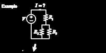
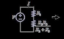
26 Example 26
27 Circuit analysis Goal: Find all element v s and i s write element v-i relationships (Ohm s law) write KCL for all nodes write KVL for all loops.2.3 lots of unknowns lots of equations lots of fun (?) solve 27
28 Element relationships For ν = i V 0 For voltage source ν = V 0 I 0 For current source i = I 0 28

29 Apply KVL KCL What do we do?! Apply element combination rules 29
30 Element combination rules 30
31 3
 ( G G")

32 Series connection ) ( G G G G G I I I I I I V eq eq eq s s s s s s s Applying KVL

33 Series connection (Applying KVL) (voltage divider circuit) voltage accross each resistor, is proportional to its resistance. Larger the resistance, larger the voltage drop on that resistor:

34 Parallel connection ) ( V V I I I I I eq eq eq s s s Applying KCL

35 Parallel connection (Applying KCL at node a) (current divider circuit) Given the total current i entering to node a the current is shared by the resistors by inverse proportion to their resistance:
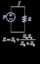
36 Equivalent resistance 36
37 Examples Calculate the eq for the following circuit. 37
38 Calculate the ab for the following circuit. 38
39 Calculate the G eq for the following circuit. 39

40 Sometimes connections are complicated There are cases where the resistors are neither in parallel nor in series 40


41 Wye-Delta Transformations Wye (Y) Networks Delta(Δ) Networks 4
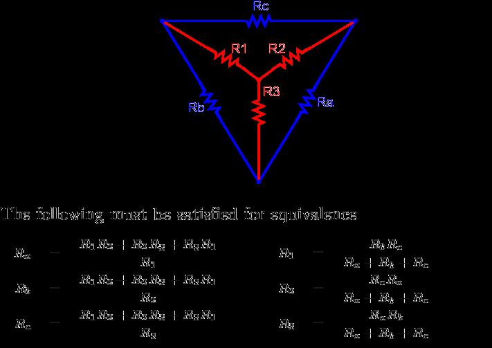
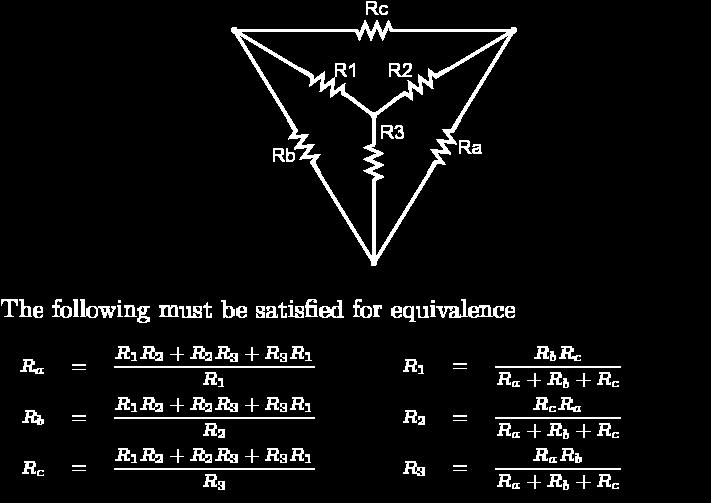
42 Wye-Delta transformation 42
43 Converting a D network to a Y network 43
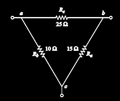
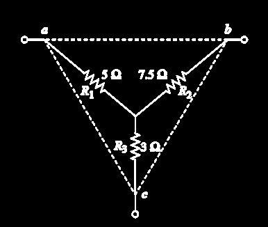
44 Examples Convert the following Ynetwork to a D network. 44
45 Examples Calculate ab and and use it to calculate i. 45

46 Examples Calculate eq and Power delivered by the source. 46
47 Examples Calculate ab and and use it to calculate i. 47
ECE 1311: Electric Circuits. Chapter 2: Basic laws
 ECE 1311: Electric Circuits Chapter 2: Basic laws Basic Law Overview Ideal sources series and parallel Ohm s law Definitions open circuits, short circuits, conductance, nodes, branches, loops Kirchhoff's
Kirchhoff's Laws and Circuit Analysis (EC 2)
") Kirchhoff's Laws and Circuit Analysis (EC ) Circuit analysis: solving for I and V at each element Linear circuits: involve resistors, capacitors, inductors Initial analysis uses only resistors Power sources,
Kirchhoff's Laws and Circuit Analysis (EC ) Circuit analysis: solving for I and V at each element Linear circuits: involve resistors, capacitors, inductors Initial analysis uses only resistors Power sources,
Lecture #3. Review: Power
 Lecture #3 OUTLINE Power calculations Circuit elements Voltage and current sources Electrical resistance (Ohm s law) Kirchhoff s laws Reading Chapter 2 Lecture 3, Slide 1 Review: Power If an element is
ECE 2100 Circuit Analysis
 ECE 2100 Circuit Analysis Lesson 3 Chapter 2 Ohm s Law Network Topology: nodes, branches, and loops Daniel M. Litynski, Ph.D. http://homepages.wmich.edu/~dlitynsk/ esistance ESISTANCE = Physical property
Chapter 2. Engr228 Circuit Analysis. Dr Curtis Nelson
 Chapter 2 Engr228 Circuit Analysis Dr Curtis Nelson Chapter 2 Objectives Understand symbols and behavior of the following circuit elements: Independent voltage and current sources; Dependent voltage and
Resistor. l A. Factors affecting the resistance are 1. Cross-sectional area, A 2. Length, l 3. Resistivity, ρ
 Chapter 2 Basic Laws. Ohm s Law 2. Branches, loops and nodes definition 3. Kirchhoff s Law 4. Series resistors circuit and voltage division. 5. Equivalent parallel circuit and current division. 6. Wye-Delta
Series & Parallel Resistors 3/17/2015 1
 Series & Parallel Resistors 3/17/2015 1 Series Resistors & Voltage Division Consider the single-loop circuit as shown in figure. The two resistors are in series, since the same current i flows in both
Electric Current. Note: Current has polarity. EECS 42, Spring 2005 Week 2a 1
 Electric Current Definition: rate of positive charge flow Symbol: i Units: Coulombs per second Amperes (A) i = dq/dt where q = charge (in Coulombs), t = time (in seconds) Note: Current has polarity. EECS
Capacitance. A different kind of capacitor: Work must be done to charge a capacitor. Capacitors in circuits. Capacitor connected to a battery
 Capacitance The ratio C = Q/V is a conductor s self capacitance Units of capacitance: Coulomb/Volt = Farad A capacitor is made of two conductors with equal but opposite charge Capacitance depends on shape
Analysis of a single-loop circuit using the KVL method
 Analysis of a single-loop circuit using the KVL method Figure 1 is our circuit to analyze. We shall attempt to determine the current through each element, the voltage across each element, and the power
ENGR 2405 Class No Electric Circuits I
 ENGR 2405 Class No. 48056 Electric Circuits I Dr. R. Williams Ph.D. rube.williams@hccs.edu Electric Circuit An electric circuit is an interconnec9on of electrical elements Charge Charge is an electrical
Review of Circuit Analysis
 Review of Circuit Analysis Fundamental elements Wire Resistor Voltage Source Current Source Kirchhoff s Voltage and Current Laws Resistors in Series Voltage Division EE 42 Lecture 2 1 Voltage and Current
Designing Information Devices and Systems I Spring 2018 Lecture Notes Note 11
 EECS 16A Designing Information Devices and Systems I Spring 2018 Lecture Notes Note 11 11.1 Context Our ultimate goal is to design systems that solve people s problems. To do so, it s critical to understand
mywbut.com Mesh Analysis
 Mesh Analysis 1 Objectives Meaning of circuit analysis; distinguish between the terms mesh and loop. To provide more general and powerful circuit analysis tool based on Kirchhoff s voltage law (KVL) only.
Basic Electrical Circuits Analysis ECE 221
 Basic Electrical Circuits Analysis ECE 221 PhD. Khodr Saaifan http://trsys.faculty.jacobs-university.de k.saaifan@jacobs-university.de 1 2 Reference: Electric Circuits, 8th Edition James W. Nilsson, and
Module 2. DC Circuit. Version 2 EE IIT, Kharagpur
 Module 2 DC Circuit Lesson 5 Node-voltage analysis of resistive circuit in the context of dc voltages and currents Objectives To provide a powerful but simple circuit analysis tool based on Kirchhoff s
Basic Laws. Bởi: Sy Hien Dinh
 Basic Laws Bởi: Sy Hien Dinh INTRODUCTION Chapter 1 introduced basic concepts such as current, voltage, and power in an electric circuit. To actually determine the values of this variable in a given circuit
Electric Circuits I. Nodal Analysis. Dr. Firas Obeidat
 Electric Circuits I Nodal Analysis Dr. Firas Obeidat 1 Nodal Analysis Without Voltage Source Nodal analysis, which is based on a systematic application of Kirchhoff s current law (KCL). A node is defined
Designing Information Devices and Systems I Fall 2018 Lecture Notes Note Resistive Touchscreen - expanding the model
 EECS 16A Designing Information Devices and Systems I Fall 2018 Lecture Notes Note 13 13.1 Resistive Touchscreen - expanding the model Recall the physical structure of the simple resistive touchscreen given
Module 2. DC Circuit. Version 2 EE IIT, Kharagpur
 Module DC Circuit Lesson 4 Loop Analysis of resistive circuit in the context of dc voltages and currents Objectives Meaning of circuit analysis; distinguish between the terms mesh and loop. To provide
Chapter 3: Electric Current and Direct-Current Circuit
 Chapter 3: Electric Current and Direct-Current Circuit n this chapter, we are going to discuss both the microscopic aspect and macroscopic aspect of electric current. Direct-current is current that flows
Notes on Electricity (Circuits)
") A circuit is defined to be a collection of energy-givers (batteries) and energy-takers (resistors, light bulbs, radios, etc.) that form a closed path (or complete path) through which electrical current
A circuit is defined to be a collection of energy-givers (batteries) and energy-takers (resistors, light bulbs, radios, etc.) that form a closed path (or complete path) through which electrical current
ELECTRICAL THEORY. Ideal Basic Circuit Element
 ELECTRICAL THEORY PROF. SIRIPONG POTISUK ELEC 106 Ideal Basic Circuit Element Has only two terminals which are points of connection to other circuit components Can be described mathematically in terms
Parallel Circuits. Chapter
 Chapter 5 Parallel Circuits Topics Covered in Chapter 5 5-1: The Applied Voltage V A Is the Same Across Parallel Branches 5-2: Each Branch I Equals V A / R 5-3: Kirchhoff s Current Law (KCL) 5-4: Resistance
COOKBOOK KVL AND KCL A COMPLETE GUIDE
 1250 COOKBOOK KVL AND KCL A COMPLETE GUIDE Example circuit: 1) Label all source and component values with a voltage drop measurement (+,- ) and a current flow measurement (arrow): By the passive sign convention,
Outline. Week 5: Circuits. Course Notes: 3.5. Goals: Use linear algebra to determine voltage drops and branch currents.
 Outline Week 5: Circuits Course Notes: 3.5 Goals: Use linear algebra to determine voltage drops and branch currents. Components in Resistor Networks voltage source current source resistor Components in
Physics 1402: Lecture 10 Today s Agenda
 Physics 1402: Lecture 10 Today s Agenda Announcements: Lectures posted on: www.phys.uconn.edu/~rcote/ HW assignments, solutions etc. Homework #3: On Masterphysics : due Friday at 8:00 AM Go to masteringphysics.com
DC CIRCUIT ANALYSIS. Loop Equations
 All of the rules governing DC circuits that have been discussed so far can now be applied to analyze complex DC circuits. To apply these rules effectively, loop equations, node equations, and equivalent
Notes on Electricity (Circuits)
") A circuit is defined to be a collection of energy-givers (active elements) and energy-takers (passive elements) that form a closed path (or complete path) through which electrical current can flow. The
A circuit is defined to be a collection of energy-givers (active elements) and energy-takers (passive elements) that form a closed path (or complete path) through which electrical current can flow. The
Lecture 1. Electrical Transport
 Lecture 1. Electrical Transport 1.1 Introduction * Objectives * Requirements & Grading Policy * Other information 1.2 Basic Circuit Concepts * Electrical l quantities current, voltage & power, sign conventions
Chapter 16. Current and Drift Speed. Electric Current, cont. Current and Drift Speed, cont. Current and Drift Speed, final
 Chapter 6 Current, esistance, and Direct Current Circuits Electric Current Whenever electric charges of like signs move, an electric current is said to exist The current is the rate at which the charge
INTRODUCTION TO ELECTRONICS
 INTRODUCTION TO ELECTRONICS Basic Quantities Voltage (symbol V) is the measure of electrical potential difference. It is measured in units of Volts, abbreviated V. The example below shows several ways
POLYTECHNIC UNIVERSITY Electrical Engineering Department. EE SOPHOMORE LABORATORY Experiment 2 DC circuits and network theorems
 POLYTECHNIC UNIVERSITY Electrical Engineering Department EE SOPHOMORE LABORATORY Experiment 2 DC circuits and network theorems Modified for Physics 18, Brooklyn College I. Overview of Experiment In this
EECE251 Circuit Analysis I Lecture Integrated Program Set 1: Basic Circuit Concepts and Elements
 EECE5 Circuit Analysis I Lecture Integrated Program Set : Basic Circuit Concepts and Elements Shahriar Mirabbasi Department of Electrical and Computer Engineering University of British Columbia shahriar@ece.ubc.ca
UNIT 4 DC EQUIVALENT CIRCUIT AND NETWORK THEOREMS
 UNIT 4 DC EQUIVALENT CIRCUIT AND NETWORK THEOREMS 1.0 Kirchoff s Law Kirchoff s Current Law (KCL) states at any junction in an electric circuit the total current flowing towards that junction is equal
Lecture # 2 Basic Circuit Laws
 CPEN 206 Linear Circuits Lecture # 2 Basic Circuit Laws Dr. Godfrey A. Mills Email: gmills@ug.edu.gh Phone: 026907363 February 5, 206 Course TA David S. Tamakloe CPEN 206 Lecture 2 205_206 What is Electrical
ENGG 225. David Ng. Winter January 9, Circuits, Currents, and Voltages... 5
 ENGG 225 David Ng Winter 2017 Contents 1 January 9, 2017 5 1.1 Circuits, Currents, and Voltages.................... 5 2 January 11, 2017 6 2.1 Ideal Basic Circuit Elements....................... 6 3 January
2. Basic Components and Electrical Circuits
 1 2. Basic Components and Electrical Circuits 2.1 Units and Scales The International System of Units (SI) defines 6 principal units from which the units of all other physical quantities can be derived
Symbol Offers Units. R Resistance, ohms. C Capacitance F, Farads. L Inductance H, Henry. E, I Voltage, Current V, Volts, A, Amps. D Signal shaping -
 Electrical Circuits HE 13.11.018 1. Electrical Components hese are tabulated below Component Name Properties esistor Simplest passive element, no dependence on time or frequency Capacitor eactive element,
Phys 2025, First Test. September 20, minutes Name:
 Phys 05, First Test. September 0, 011 50 minutes Name: Show all work for maximum credit. Each problem is worth 10 points. Work 10 of the 11 problems. k = 9.0 x 10 9 N m / C ε 0 = 8.85 x 10⁻¹ C / N m e
Solution: Based on the slope of q(t): 20 A for 0 t 1 s dt = 0 for 3 t 4 s. 20 A for 4 t 5 s 0 for t 5 s 20 C. t (s) 20 C. i (A) Fig. P1.
: 20 A for 0 t 1 s dt = 0 for 3 t 4 s. 20 A for 4 t 5 s 0 for t 5 s 20 C. t (s) 20 C. i (A) Fig. P1.") Problem 1.24 The plot in Fig. P1.24 displays the cumulative charge q(t) that has entered a certain device up to time t. Sketch a plot of the corresponding current i(t). q 20 C 0 1 2 3 4 5 t (s) 20 C Figure
Problem 1.24 The plot in Fig. P1.24 displays the cumulative charge q(t) that has entered a certain device up to time t. Sketch a plot of the corresponding current i(t). q 20 C 0 1 2 3 4 5 t (s) 20 C Figure
Circuit Theorems Overview Linearity Superposition Source Transformation Thévenin and Norton Equivalents Maximum Power Transfer
 Circuit Theorems Overview Linearity Superposition Source Transformation Thévenin and Norton Equivalents Maximum Power Transfer J. McNames Portland State University ECE 221 Circuit Theorems Ver. 1.36 1
Designing Information Devices and Systems I Spring 2015 Note 11
 EECS 16A Designing Information Devices and Systems I Spring 2015 Note 11 Lecture notes by Edward Wang (02/26/2015). Resistors Review Ohm s law: V = IR Water pipe circuit analogy: Figure 1: Water analogy
DC STEADY STATE CIRCUIT ANALYSIS
 DC STEADY STATE CIRCUIT ANALYSIS 1. Introduction The basic quantities in electric circuits are current, voltage and resistance. They are related with Ohm s law. For a passive branch the current is: I=
Voltage Dividers, Nodal, and Mesh Analysis
 Engr228 Lab #2 Voltage Dividers, Nodal, and Mesh Analysis Name Partner(s) Grade /10 Introduction This lab exercise is designed to further your understanding of the use of the lab equipment and to verify
Massachusetts Institute of Technology Department of Electrical Engineering and Computer Science : Circuits & Electronics Problem Set #1 Solution
 Massachusetts Institute of Technology Department of Electrical Engineering and Computer Science 6.2: Circuits & Electronics Problem Set # Solution Exercise. The three resistors form a series connection.
Circuit Theory I Basic Concepts
 Circuit Theory I Basic Concepts Assistant Professor Suna BOLAT Eastern Mediterranean University Electric and electronic department AnantAgarwaland Jeffrey Lang, course materials for 6.002 Circuits and
Introduction. Pre-lab questions: Physics 1BL KIRCHOFF S RULES Winter 2010
 Introduction In this lab we will examine more complicated circuits. First, you will derive an expression for equivalent resistance using Kirchhoff s Rules. Then you will discuss the physics underlying
D C Circuit Analysis and Network Theorems:
 UNIT-1 D C Circuit Analysis and Network Theorems: Circuit Concepts: Concepts of network, Active and passive elements, voltage and current sources, source transformation, unilateral and bilateral elements,
EXPERIMENT THREE DC CIRCUITS
 EXEMET THEE DC CCUT EQUMET EEDED: ) DC ower upply ) DMM 3) esistors 4) EL THEOY Kirchhoff's Laws: Kirchhoff's oltage Law: The algebraic sum of the voltages around any closed path is zero. v i i 0 3. Kirchhoff's
Phy301- Circuit Theory
 Phy301- Circuit Theory Solved Mid Term MCQS and Subjective with References. Question No: 1 ( Marks: 1 ) - Please choose one If we connect 3 capacitors in series, the combined effect of all these capacitors
Engineering Fundamentals and Problem Solving, 6e
 Engineering Fundamentals and Problem Solving, 6e Chapter 17 Electrical Circuits Chapter Objectives Compute the equivalent resistance of resistors in series and in parallel Apply Ohm s law to a resistive
Notes for course EE1.1 Circuit Analysis TOPIC 3 CIRCUIT ANALYSIS USING SUB-CIRCUITS
 Notes for course EE1.1 Circuit Analysis 2004-05 TOPIC 3 CIRCUIT ANALYSIS USING SUB-CIRCUITS OBJECTIVES 1) To introduce the Source Transformation 2) To consider the concepts of Linearity and Superposition
ES250: Electrical Science. HW1: Electric Circuit Variables, Elements and Kirchhoff s Laws
 ES250: Electrical Science HW1: Electric Circuit Variables, Elements and Kirchhoff s Laws Introduction Engineers use electric circuits to solve problems that are important to modern society, such as: 1.
R R V I R. Conventional Current. Ohms Law V = IR
 DC Circuits opics EMF and erminal oltage esistors in Series and in Parallel Kirchhoff s ules EMFs in Series and in Parallel Capacitors in Series and in Parallel Ammeters and oltmeters Conventional Current
Lecture Notes on DC Network Theory
 Federal University, Ndufu-Alike, Ikwo Department of Electrical/Electronics and Computer Engineering (ECE) Faculty of Engineering and Technology Lecture Notes on DC Network Theory Harmattan Semester by
Chapter 27: Current and Resistance
 Chapter 7: Current and esistance In this section of the course we will be studying the flow of electric charge, current, in a circuit. We have already seen electric current when we first discussed electric
10/14/2018. Current. Current. QuickCheck 30.3
 Current If QCurrent is the total amount of charge that has moved past a point in a wire, we define the current I in the wire to be the rate of charge flow: The SI unit for current is the coulomb per second,
ENGI 1040: ELECTRIC CIRCUITS Winter Part I Basic Circuits
 1. Electric Charge ENGI 1040: ELECTRIC CIRCUITS Winter 2018 Part I Basic Circuits atom elementary unit of a material which contains the properties of that material can be modeled as negatively charged
AP Physics C. Electric Circuits III.C
 AP Physics C Electric Circuits III.C III.C.1 Current, Resistance and Power The direction of conventional current Suppose the cross-sectional area of the conductor changes. If a conductor has no current,
Basic Electricity. Unit 2 Basic Instrumentation
 Basic Electricity Unit 2 Basic Instrumentation Outlines Terms related to basic electricity-definitions of EMF, Current, Potential Difference, Power, Energy and Efficiency Definition: Resistance, resistivity
In this unit, we will examine the movement of electrons, which we call CURRENT ELECTRICITY.
 Recall: Chemistry and the Atom! What are the 3 subatomic Where are they found in the particles? atom? What electric charges do they have? How was a positive ion created? How was a negative ion created?
EE292: Fundamentals of ECE
 EE292: Fundamentals of ECE Fall 2012 TTh 10:00-11:15 SEB 1242 Lecture 4 120906 http://www.ee.unlv.edu/~b1morris/ee292/ 2 Outline Review Voltage Divider Current Divider Node-Voltage Analysis 3 Network Analysis
Chapter 3: Electric Current And Direct-Current Circuits
 Chapter 3: Electric Current And Direct-Current Circuits 3.1 Electric Conduction 3.1.1 Describe the microscopic model of current Mechanism of Electric Conduction in Metals Before applying electric field
EIT Review. Electrical Circuits DC Circuits. Lecturer: Russ Tatro. Presented by Tau Beta Pi The Engineering Honor Society 10/3/2006 1
 EIT Review Electrical Circuits DC Circuits Lecturer: Russ Tatro Presented by Tau Beta Pi The Engineering Honor Society 10/3/2006 1 Session Outline Basic Concepts Basic Laws Methods of Analysis Circuit
QUIZ 1 SOLUTION. One way of labeling voltages and currents is shown below.
 F 14 1250 QUIZ 1 SOLUTION EX: Find the numerical value of v 2 in the circuit below. Show all work. SOL'N: One method of solution is to use Kirchhoff's and Ohm's laws. The first step in this approach is
Chapter 21 Electric Current and Direct- Current Circuits
 Chapter 21 Electric Current and Direct- Current Circuits 1 Overview of Chapter 21 Electric Current and Resistance Energy and Power in Electric Circuits Resistors in Series and Parallel Kirchhoff s Rules
Insulators Non-metals are very good insulators; their electrons are very tightly bonded and cannot move.
 SESSION 11: ELECTRIC CIRCUITS Key Concepts Resistance and Ohm s laws Ohmic and non-ohmic conductors Series and parallel connection Energy in an electric circuit X-planation 1. CONDUCTORS AND INSULATORS
LESSON 5: ELECTRICITY II
 LESSON 5: ELECTRICITY II The first two points are a review of the previous lesson 1.1.ELECTRIC CHARGE - Electric charge is a property of all objects and is responsible for electrical phenomena. -All matter
Direct-Current Circuits. Physics 231 Lecture 6-1
 Direct-Current Circuits Physics 231 Lecture 6-1 esistors in Series and Parallel As with capacitors, resistors are often in series and parallel configurations in circuits Series Parallel The question then
Direct Current Circuits. February 18, 2014 Physics for Scientists & Engineers 2, Chapter 26 1
 Direct Current Circuits February 18, 2014 Physics for Scientists & Engineers 2, Chapter 26 1 Kirchhoff s Junction Rule! The sum of the currents entering a junction must equal the sum of the currents leaving
Basics of Network Theory (Part-I)
") Basics of Network Theory (PartI). A square waveform as shown in figure is applied across mh ideal inductor. The current through the inductor is a. wave of peak amplitude. V 0 0.5 t (m sec) [Gate 987: Marks]
Basics of Network Theory (PartI). A square waveform as shown in figure is applied across mh ideal inductor. The current through the inductor is a. wave of peak amplitude. V 0 0.5 t (m sec) [Gate 987: Marks]
Delta & Y Configurations, Principles of Superposition, Resistor Voltage Divider Designs
 BME/ISE 3511 Bioelectronics - Test Three Course Notes Fall 2016 Delta & Y Configurations, Principles of Superposition, esistor Voltage Divider Designs Use following techniques to solve for current through
CHAPTER 1 ELECTRICITY
 CHAPTER 1 ELECTRICITY Electric Current: The amount of charge flowing through a particular area in unit time. In other words, it is the rate of flow of electric charges. Electric Circuit: Electric circuit
Homework 2. Due Friday (5pm), Feb. 8, 2013
, Feb. 8, 2013") University of California, Berkeley Spring 2013 EE 42/100 Prof. K. Pister Homework 2 Due Friday (5pm), Feb. 8, 2013 Please turn the homework in to the drop box located next to 125 Cory Hall (labeled EE
University of California, Berkeley Spring 2013 EE 42/100 Prof. K. Pister Homework 2 Due Friday (5pm), Feb. 8, 2013 Please turn the homework in to the drop box located next to 125 Cory Hall (labeled EE
1 S = G R R = G. Enzo Paterno
 ECET esistie Circuits esistie Circuits: - Ohm s Law - Kirchhoff s Laws - Single-Loop Circuits - Single-Node Pair Circuits - Series Circuits - Parallel Circuits - Series-Parallel Circuits Enzo Paterno ECET
ENGR 2405 Chapter 6. Capacitors And Inductors
 ENGR 2405 Chapter 6 Capacitors And Inductors Overview This chapter will introduce two new linear circuit elements: The capacitor The inductor Unlike resistors, these elements do not dissipate energy They
Notes for course EE1.1 Circuit Analysis TOPIC 4 NODAL ANALYSIS
 Notes for course EE1.1 Circuit Analysis 2004-05 TOPIC 4 NODAL ANALYSIS OBJECTIVES 1) To develop Nodal Analysis of Circuits without Voltage Sources 2) To develop Nodal Analysis of Circuits with Voltage
Chapter 25 Electric Currents and. Copyright 2009 Pearson Education, Inc.
 Chapter 25 Electric Currents and Resistance 25-1 The Electric Battery Volta discovered that electricity could be created if dissimilar metals were connected by a conductive solution called an electrolyte.
DC Circuits. Electromotive Force Resistor Circuits. Kirchoff s Rules. RC Circuits. Connections in parallel and series. Complex circuits made easy
 DC Circuits Electromotive Force esistor Circuits Connections in parallel and series Kirchoff s ules Complex circuits made easy C Circuits Charging and discharging Electromotive Force (EMF) EMF, E, is the
Electric Current, Resistance and Resistivity. Brief otes
 Electric current, resistance and restivity Electric Current, esistance and esistivity In This small e-book we will learn all we need to know about current electricity but in short and then we ll have some
EE40 KVL KCL. Prof. Nathan Cheung 09/01/2009. Reading: Hambley Chapter 1
 EE40 KVL KCL Prof. Nathan Cheung 09/01/2009 Reading: Hambley Chapter 1 Slide 1 Terminology: Nodes and Branches Node: A point where two or more circuit elements are connected Branch: A path that connects
Homework 1 solutions
 Electric Circuits 1 Homework 1 solutions (Due date: 2014/3/3) This assignment covers Ch1 and Ch2 of the textbook. The full credit is 100 points. For each question, detailed derivation processes and accurate
BFF1303: ELECTRICAL / ELECTRONICS ENGINEERING
 BFF1303: ELECTRICAL / ELECTRONICS ENGINEERING Introduction Ismail Mohd Khairuddin, Zulkifil Md Yusof Faculty of Manufacturing Engineering Universiti Malaysia Pahang Introduction BFF1303 ELECTRICAL/ELECTRONICS
Electrical Technology (EE-101-F)
") Electrical Technology (EE-101-F) Contents Series & Parallel Combinations KVL & KCL Introduction to Loop & Mesh Analysis Frequently Asked Questions NPTEL Link Series-Parallel esistances 1 V 3 2 There are
Electrical Technology (EE-101-F) Contents Series & Parallel Combinations KVL & KCL Introduction to Loop & Mesh Analysis Frequently Asked Questions NPTEL Link Series-Parallel esistances 1 V 3 2 There are
Kirchhoff's Laws and Maximum Power Transfer
 German Jordanian University (GJU) Electrical Circuits Laboratory Section Experiment Kirchhoff's Laws and Maximum Power Transfer Post lab Report Mahmood Hisham Shubbak / / 8 Objectives: To learn KVL and
Come & Join Us at VUSTUDENTS.net
 Come & Join Us at VUSTUDENTS.net For Assignment Solution, GDB, Online Quizzes, Helping Study material, Past Solved Papers, Solved MCQs, Current Papers, E-Books & more. Go to http://www.vustudents.net and
Clicker Session Currents, DC Circuits
 Clicker Session Currents, DC Circuits Wires A wire of resistance R is stretched uniformly (keeping its volume constant) until it is twice its original length. What happens to the resistance? 1) it decreases
E E 2320 Circuit Analysis. Calculating Resistance
 E E 30 Circuit Analysis Lecture 03 Simple esistive Circuits it and Applications Calculating esistance l A 6 1.67 10 cm cu 6 al.7010 Area, A When conductor has uniform crosssection cm l 1 Temperature Coefficient
Physics 142 Steady Currents Page 1. Steady Currents
 Physics 142 Steady Currents Page 1 Steady Currents If at first you don t succeed, try, try again. Then quit. No sense being a damn fool about it. W.C. Fields Electric current: the slow average drift of
Physics 1214 Chapter 19: Current, Resistance, and Direct-Current Circuits
 Physics 1214 Chapter 19: Current, Resistance, and Direct-Current Circuits 1 Current current: (also called electric current) is an motion of charge from one region of a conductor to another. Current When
In this lecture, we will consider how to analyse an electrical circuit by applying KVL and KCL. As a result, we can predict the voltages and currents
 In this lecture, we will consider how to analyse an electrical circuit by applying KVL and KCL. As a result, we can predict the voltages and currents around an electrical circuit. This is a short lecture,
CHAPTER FOUR CIRCUIT THEOREMS
 4.1 INTRODUCTION CHAPTER FOUR CIRCUIT THEOREMS The growth in areas of application of electric circuits has led to an evolution from simple to complex circuits. To handle the complexity, engineers over
Brian Blais Quick Homemade Guide to Circuits
 Brian Blais Quick Homemade Guide to Circuits 1 Initial Equations and Concepts Current, I. Units:amps rate of flow of charge: I = Q/ t Potential difference, V. Units: volts esistance,. Units:ohms Ohm s
R 2, R 3, and R 4 are in parallel, R T = R 1 + (R 2 //R 3 //R 4 ) + R 5. C-C Tsai
 + R 5. C-C Tsai") Chapter 07 Series-Parallel Circuits The Series-Parallel Network Complex circuits May be separated both series and/or parallel elements Combinations which are neither series nor parallel To analyze a circuit
Chapter 07 Series-Parallel Circuits The Series-Parallel Network Complex circuits May be separated both series and/or parallel elements Combinations which are neither series nor parallel To analyze a circuit
CURRENT SOURCES EXAMPLE 1 Find the source voltage Vs and the current I1 for the circuit shown below SOURCE CONVERSIONS
 CURRENT SOURCES EXAMPLE 1 Find the source voltage Vs and the current I1 for the circuit shown below EXAMPLE 2 Find the source voltage Vs and the current I1 for the circuit shown below SOURCE CONVERSIONS
Chapter 6 DIRECT CURRENT CIRCUITS. Recommended Problems: 6,9,11,13,14,15,16,19,20,21,24,25,26,28,29,30,31,33,37,68,71.
 Chapter 6 DRECT CURRENT CRCUTS Recommended Problems: 6,9,,3,4,5,6,9,0,,4,5,6,8,9,30,3,33,37,68,7. RESSTORS N SERES AND N PARALLEL - N SERES When two resistors are connected together as shown we said that
Lecture Outline Chapter 21. Physics, 4 th Edition James S. Walker. Copyright 2010 Pearson Education, Inc.
 Lecture Outline Chapter 21 Physics, 4 th Edition James S. Walker Chapter 21 Electric Current and Direct- Current Circuits Units of Chapter 21 Electric Current Resistance and Ohm s Law Energy and Power
Electroscope Used to are transferred to the and Foil becomes and
 Electricity Notes Chapter 17 Section 1: Electric Charge and Forces Electric charge is a variety of independent all with one single name. Electricity is related to, and both (-) and (+) carry a charge.
Chapter 28. Direct Current Circuits
 Chapter 28 Direct Current Circuits Circuit Analysis Simple electric circuits may contain batteries, resistors, and capacitors in various combinations. For some circuits, analysis may consist of combining