Chapter 3: Electric Current and Direct-Current Circuit
|
|
|
- Blanche Robertson
- 5 years ago
- Views:
Transcription


1 Chapter 3: Electric Current and Direct-Current Circuit n this chapter, we are going to discuss both the microscopic aspect and macroscopic aspect of electric current. Direct-current is current that flows in one direction.
2 Overview Electric Current Conduction of Electricity dq dt Ohm s Law Electrical Energy W t Drift elocity esistivity Electrical Power v d nae A l P Dependence of esistance on Temperature T T 0 0
3 Overview Direct-Current Circuit Electromotive Force, nternal esistor & Potential Difference terminal r First Law Kirchhoff s Laws Second Law Potential Divider 2 in out Potentiometer 2 l l 2 esistors Wheatstone Bridge n Series n Parallel X 2 3
4 3. Electric Conduction Describe microscopic model of current Define and use electric current, dq dt Learning Objectives
5 Mechanism of Electric Conduction in Metals v d 0 Before applying electric field Electron move freely and random. Frequently interact with each other. Drift velocity is zero because the free electrons are in constant random motion.
6 Mechanism of Electric Conduction in Metals After applying electric field E v d v d nae F e The freely moving electron experience an electric force and tend to drift towards a direction opposite to the direction of electric field (positive terminal of the battery). The electric current is flowing in the opposite direction of the electron flows. Drift velocity is the mean velocity of the electrons parallel to the direction of the electric field when a potential difference is applied.
7 Electric Current Electric current, is defined as the total charge, Q flowing through an area per unit time, t. (O the rate of charge flow through a conductor) Mathematically, Q t O dq dt t is a scalar quantity. The S.. unit for electric current is ampere (A).
8 Example A current of 2.0 A flows through a copper wire. Calculate a. the amount of charge, and b. the number of electrons flow through a cross-sectional area of the copper wire in 30 s. (Given the charge of electron, e =.60x0-9 C)
9 Example Solution
10 Example Solution
11 3.2 Ohm s Law and esistivity State and use Ohm s Law Define and use resistivity, A l Learning Objectives
12 Ohm s Law Ohm s law states that the potential difference across a conductor, is directly proportional to the current, through it, if its physical conditions and the temperature are constant. where T is constant Mathematically, constant Ohm s Law equation
13 Ohm s Law Graphically, Must start from zero Not all materials obey Ohm s law. Materials that obey Ohm s law are materials that have constant resistance over a wide range of voltage. These materials are called ohmic conductor. Examples: pure metals
14 esistivity esistivity is defined as the resistance of a unit crosssectional area per unit length of the material. t is a measure of a material s ability to oppose the flow of an electric current. A l where l : length A : cross-sectional area t is a scalar quantity Unit is ohm meter ( m) esistivity depends on the material. Same materials have same resistivity. t only changes when the temperature of wire/ material changes.
15 Example 2 A wire 4.00 m long and 6.00 mm in diameter has a resistance of 5 m. A potential difference of 23.0 is applied between both end. Determine a. the current in the wire. b. the resistivity of the wire material.
16 Example 2 Solution
17 Example 2 Solution
18 Example 3 Two wires P and Q with circular cross section are made of the same metal and have equal length. f the resistance of wire P is three times greater than that of wire Q, determine the ratio of their diameters.
19 Example 3 Solution
20 3.3 ariation of esistance with Temperature Explain the effect of temperature on electrical resistance in metals. Use resistance, T T 0 0 Learning Objectives
21 Electric esistance of A Metal The resistance of a metal (conductor) depends on a. the nature of the material, (, resistivity) b. the size of the conductor, (l, the length and A, cross-sectional area) l A c. the temperature of the conductor. The resistance of metals increases with increasing temperature. (T, )
22 The Effect of Temperature on Electrical esistance in Metals Explanation:. As temperature increases, the ions of the conductor vibrate with greater amplitude. 2. More collisions occur between free electrons and ions. 3. These electrons are slowed down thus increases the resistance.
23 ariation of esistance with Temperature The fractional change in resistance per unit rise in temperature is known as temperature coefficient of resistance, α: α is a constant value and it is depends on the material. T 0 T T T T T T
24 ariation of esistance with Temperature The resistance of a metal can be represented by the equation below: T T 0 0 where = the resistance at temperature T, o = the resistance at temperature T 0 = 20 o C or 0 o C, T = final temperature T o = reference temperature (20 o C or 0 o C) = the temperature coefficient of resistance ( o C - )
25 Example 4 A platinum wire has a resistance of 0.5 Ω at 0 C. t is placed in a water bath where its resistance rises to a final value of 0.6 Ω. What is the temperature of the bath? (Given the temperature coefficient of resistance of platinum is C - )
26 Example 4 Solution
27 Example 5 A copper wire has a resistance of 25 mω at 20 C. When the wire is carrying a current, heat produced by the current causes the temperature of the wire to increase by 27 C. a. Calculate the change in the wire s resistance. b. f its original current was 0.0 ma and the potential difference across wire remains constant, determine the final current of the copper wire. (Given the temperature coefficient of resistance of copper is C - )
28 Example 5 Solution
29 Example 5 Solution
30 3.4 Electromotive Force (emf), nternal esistance and Potential Difference Define emf, ε of a battery Explain the relationship between emf of a battery and potential difference across the battery terminals Use terminal voltage r Learning Objectives

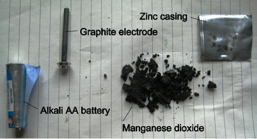
31 What is inside a battery

32 How do batteries work?
, is defined as the energy provided by the source (battery/ cell) to each unit charge that flows from the source.")
33 Electromotive Force, ε ε Electromotive force (e.m.f.), is defined as the energy provided by the source (battery/ cell) to each unit charge that flows from the source. t is the maximum potential difference across its terminals when it is not connected to a circuits. Unit is volt ().
.")
34 Terminal Potential Difference, Terminal potential difference (voltage), is defined as the work done in bringing a unit (test) charge from the negative to the positive terminals of the battery through the external resistance only. t is the potential difference across the terminals of a battery when there is a current flowing through it. Unit is volt ().
35 nternal esistance, r n a cell or battery, the negative ions are attracted by anode and the positive ions are attracted by the cathode. The flow of these ions produces current. However the collisions between the ions and the recombination of opposite ions reduce the flow of current. This resistance in the cell is called internal resistance, r.
36 elationship between ε, and r terminal lost r r Total resistance in the circuit

37 Note terminal < ε when the battery of emf ε is connected to the external circuit with resistance. terminal > ε when the battery of emf ε is being charged by other battery. terminal = ε when the battery of emf ε has no internal resistance (r = 0) and connected to the external circuit with resistance.
38 Example 6 A battery of internal resistance 0.3 is connected across a 5.0 resistor. The terminal potential difference measured by the voltmeter is 2.5. Calculate the e.m.f. of the battery.
39 Example 6 Solution
40 Example 7 When a 0 resistor is connected across the terminals of a cell of e.m.f. and internal resistance r, a current of 0.0 A flows through the resistor. f the 0 resistor is replaced with a 3.0 resistor, the current increases to 0.24 A. Find and r.

41 Example 7 Solution
42 Example 7 Solution
43 Example 8 A battery has an e.m.f. of 9.0 and an internal resistance of 6.0. Determine a. the potential difference across its terminals when it is supplying a current of 0.50 A, b. the maximum current which the battery could supply.
44 Example 8 Solution
45 Example 8 Solution
46 3.5 Electrical Energy and Power Use power, P = electrical energy, W = t Learning Objectives
47 Electrical Energy, W Electrical (potential) energy, W is the energy gained by the charge Q from a voltage source (battery) having a terminal voltage. The faster the electric charges are moving the more electrical energy they carry. The work done by the source on the charge is given by: Given Q = t, W Q W t For source
48 Electrical Energy, W Since =, electrical energy can also be written as: W 2 t O W 2 t The unit for electrical energy is Joule (J).
49 Electrical Power, P Electric power is defined as the rate of energy delivered to the external circuit by the battery. P W t t t P For source Since =, electrical power can also be written as: P 2 O P 2 The unit for electrical power is Watt (W).
50 Example 9 a. Calculate the resistance of a 40 W automobile headlight designed for 2? b. The current through a refrigerator of resistance 2 Ω is 3 A. What is the power consumed by the refrigerator?
51 Example 9 Solution

52 Example 0 n figure above, a battery with an e.m.f. of 2 and an internal resistance of.0 is connected to a 5Ω resistor. Determine a. the rate of energy transferred to electrical energy in the battery, b. the rate of heat dissipated in the battery, c. the amount of heat loss in the 5.0 resistor if the current flows through it for 20 minutes.
53 Example 0 Solution
54 Example 0 Solution
55 evision a. A dry cell of e.m.f..50 is connected in series with a resistor and another battery. When a current of 3.0 A flows from the cell, the voltage across the cell is What is the internal resistance of the dry cell? (0.36 Ω) b. The e.m.f. of a cell is.5 and its internal resistance is 0.5 Ω. Determine the power supplied to an external resistor of resistance 2.5 Ω. (0.625 W)
56 3.6 esistors in Series and Parallel Derive and determine effective resistance of resistors in series and parallel Learning Objectives
57 esistor in Series The symbol of resistor in electrical circuit can be shown in esistors in Series O
58 esistor in Series The same current flows through each resistor where 2 3 Assuming that the connecting wires have no resistance, the total potential difference, is given by 2 3 From the definition of resistance, ; 2 2 ; 3 3 ; eq Therefore, eq 2 3 eq 2 3
59 esistor in Parallel esistors in Parallel
60 esistor in Parallel There is the same potential difference, across each resistor where 2 3 Charge is conserved, therefore the total current in the circuit is given by 2 3 From the definition of resistance, ; 2 ; 3 ; 2 3 Therefore, eq 2 3 eq eq 2 3

61 Example For the circuit shown below, Calculate : a. the total resistance of the circuit. b. the total current in the circuit. c. the potential difference across 4.0 resistor.
62 Example Solution
63 Example Solution

64 Example 2 For the circuit shown below, calculate the equivalent resistance between points x and y.
65 Example 2 Solution
66 A B 5 Since 4 and 5 are in series: X 4 5 X is constant from point A to point B. A 3 Step X X 3 3 B
67 A X B X Since X and 2 have same potential difference (point A and B), they are in parallel: Y Y Y X X Step 2 Y Y Y 3 3
68 A Y Y 3 Y Since Y and 3 are in series: Z Z Y 3 Y is constant from point A to point C. Y 3 C 3 A Step 3 Z Z Y C
69 A C Z Z Y Since Z and have same potential difference (point A and C), they are in parallel: eq eq eq Z Y Z Step 4 eq eq eq Answer: eq 0.79
70 3.7 Kirchhoff s Laws State and use Kirchhoff s Laws (Maximum two closed circuit loops) Learning Objectives
71 Kirchhoff s First Laws Also known as Kirchhoff s Junction/Current Law States the algebraic sum of the currents entering any junctions in a circuit must equal the algebraic sum of the currents leaving that junction. Obeys the principle of conservation of charge. Mathematically, For example: in out
72 Kirchhoff s Second Laws Also known as Kirchhoff s Loop/oltage Law States in any closed loop, the algebraic sum of e.m.f.s is equal to the algebraic sum of the products of current and resistance or in any closed loop. Obeys the principle of conservation of energy. Mathematically,

73 Kirchhoff s Second Laws Sign convention for e.m.f., ε: Sign convention for the product of :
74 Problem Solving Strategy For ONE closed circuit. Label the diagram 2. Apply Kirchhoff s Second Law equation 3. Solve the equations Only one loop, no junction in the circuit: Don t have to apply Kirchhoff s first law ɛ ɛ 2 2 Kirchhoff s second law:
75 Problem Solving Strategy For TWO closed circuits. Label the diagram 2. Apply Kirchhoff s First Law equation 3. Apply Kirchhoff s Second Law 2 equations 4. Use scientific calculator to solve the simultaneous equations ε Kirchhoff s first law: in out ε Kirchhoff s second law: Loop : 2 22 Loop 2: ( ) 3


76 Example 3 Using Kirchhoff s rules, find the current in each resistor.
77 Example 3 Solution

78 Example 4 Calculate, ε X and
79 Example 4 Solution Step : Label the diagram ε X = Ω 0.84 A ε Y Ω A Step 2: Apply Kirchhoff s First Law in 2 out A
80 Example 4 Solution Step 3: Apply Kirchhoff s Second Law ε X = 7.2 ε Y 4.0 Ω Ω 0.84 A Loop : X Y A 2 Loop 2: Y 2 2 2
81 Example 4 Solution Step 4: Solving the simultaneous equations Loop : Y X Y Y 9.84 Loop 2: Y 9.84 Y Y (.68.0) (0.32 ) 33.0


82 Example 5 Using Kirchhoff s rules, find the current in each resistor. Answer: =3.75 A, 2 = 5.0 A, 3 =.25 A

83 Example 6 For the circuit shown below, Given = 8, 2 = 2, 3 = 3, = and = 3 A. gnore the internal resistance in each battery. Calculate a. the currents and 2. b. the e.m.f. 2. Answer: A, 4 A, 7

84 Example 7 For the circuit shown below, Determine a. the currents, 2 and 3, b. the potential difference across the 6.7 resistor, c. the power dissipated from the.2 resistor. Answer: =0.72 A, 2 =.03 A, 3 =.75 A ; 6.90 ; 3.68 W
85 3.8 Potential Divider Explain principle of potential divider Use equation of potential divider, 2 Learning Objectives
86 Potential Divider Also known as voltage divider. A potential divider produces an output voltage that is a fraction of the supply voltage. This is done by connecting two resistors in series as shown in figure below. 2 Since the current flowing through each resistor is the same, thus eq and eq 2 2 2
87 Potential Divider Therefore, the potential difference (voltage) across is given by 2 Similarly,
88 Potential Divider esistance and 2 can be replaced by a uniform homogeneous wire as shown in figure below. a l c l 2 2 b Since ρl A Therefore, the potential difference (voltage) across the wire with length l l l 2 and l2 2 l l 2
89 Summary 2 2 a l c l 2 2 b l eff 2 2 l total l l 2 2
90 Example 8 esistors of 3.0 Ω and 6.0 Ω are connected in series to a 2.0 battery of negligible internal resistance. Determine the potential difference across the a. 3.0 Ω resistor b. 6.0 Ω resistors
91 Example 8 Solution
92 3.9 Potentiometer and Wheatstone Bridge Explain principles of potentiometer and Wheatstone Bridge and their applications. Use related equations for potentiometer, and for Wheatstone Bridge, 2 l l 2 2 X Learning Objectives
93 Potentiometer 0 0 G No current flow 8 0
94 Potentiometer The working of potentiometer is based upon the fact that fall of the potential across any portion of the wire is directly proportional to the length of the wire provided wire has uniform cross section area and constant current flowing through it. A + - x G C (Unknown oltage) l because l B Jockey The potentiometer is balanced when the jockey (sliding contact) is at such a position on wire AB that there is no current through the galvanometer. Galvanometer reading = 0
 G Jockey The")

95 Application : To measure the unknown e.m.f. C A B + - x (Unknown oltage) G Jockey The potentiometer is balanced when the reading of galvanometer is equal to zero (no current through the galvanometer). X AC
96 Application : To measure the unknown e.m.f. A l Total G C B a l c l 2 2 b AC BC Same as potential divider l Total l AC AC l BC BC
 A")
97 Application 2: To compare two e.m.f. l l l A earranging: l () A
98 Application 2: To compare two e.m.f. 2 l2 l2 l A 2 earranging: 2 l (2) A 2
 (2) = A l A l 2 2 2 2 l l or 2 2")
99 Application 2: To compare two e.m.f. () (2) = A l A l l l or 2 2 l
100 Application 3: To measure the internal resistance of a cell l0 l0 earranging: l A 0 l () A 0
101 Application 3: To measure the internal resistance of a cell Circuit t l l l A Circuit 2 earranging: t l A (2)
102 Application 3: To measure the internal resistance of a cell When switch is CLOSED, circuit 2 has current flow now. When there is current flow, the battery has internal resistance due to the chemical reaction inside the battery. So for circuit 2, t r earranging r t t t t Substitute r (3)
103 Application 3: To measure the internal resistance of a cell Substitute () and (2) into (3): earranging: l l l r 0 c x m y 0 l 0 l r l or l l r 0
104 Example 9 Consider a potentiometer: f a standard battery with an e.m.f. of.086 is used in the circuit, the galvanometer reads zero when the resistance is 36 Ω. f the standard battery is replaced by an unknown e.m.f. the galvanometer reads zero when the resistance is adjusted to 48 Ω. What is the value of the unknown e.m.f.?
105 Example 9 Solution
106 Example 20 n the potentiometer circuit shown below, PQ is a uniform wire of length.0 m and resistance 0.0. is an accumulator of e.m.f. 2.0 and negligible internal resistance. is a 5 resistor and 2 is a 5.0 resistor when S and S 2 open, galvanometer G is balanced when QT is 62.5 cm. When both S and S 2 are closed, the balance length is 0.0 cm. Calculate a. the e.m.f. of cell 2. b. the internal resistance of cell 2.
107 Example 20 Solution
108 Example 20 Solution
109 Example 20 Solution
110 Wheatstone Bridge t is used to measured the unknown resistance of the resistor. Figure below shows the Wheatstone bridge circuit consists of a cell of e.m.f. (accumulator), a galvanometer, know resistances (, 2 and 3 ) and unknown resistance x. The Wheatstone bridge is said to be balanced when no current flows through the galvanometer.
111 Wheatstone Bridge When the Wheatstone Bridge is balanced: AC AD CB DB 2 Potential at C = Potential at D AC AD and BC BD Since =, and 2 2X 23 Dividing gives: X X
112 Application: Metre Bridge The metre bridge is balanced when the jockey J is at such a position on wire AB that there is no current through the galvanometer. X l l 2
113 Example 2 An unknown length of platinum wire mm in diameter is placed as the unknown resistance in a Wheatstone bridge as shown in figure below. esistors and 2 have resistance of 38.0 and 46.0 respectively. Balance is achieved when the switch closed and 3 is Find the length of the platinum wire if its resistivity is 0.6 x 0-8 m.
114 Example 2 Solution
115 Summary Electric Current Conduction of Electricity dq dt Ohm s Law Electrical Energy W t Drift elocity esistivity Electrical Power v d nae A l P Dependence of esistance on Temperature T T 0 0
116 Summary Direct-Current Circuit Electromotive Force, nternal esistor & Potential Difference terminal r First Law Kirchhoff s Laws Second Law Potential Divider 2 in out Potentiometer 2 l l 2 esistors Wheatstone Bridge n Series n Parallel X 2 3

117
Chapter 3: Electric Current And Direct-Current Circuits
 Chapter 3: Electric Current And Direct-Current Circuits 3.1 Electric Conduction 3.1.1 Describe the microscopic model of current Mechanism of Electric Conduction in Metals Before applying electric field
UNIT 5: Electric Current and Direct-Current Circuit (D.C.)
") UNT 5: Electric Current Direct-Current Circuit (D.C.) SF07 5. Electric Current, Consider a simple closed circuit consists of wires, a battery a lamp as shown in figure 5.a. F r e E r rea, From the figure,
UNT 5: Electric Current Direct-Current Circuit (D.C.) SF07 5. Electric Current, Consider a simple closed circuit consists of wires, a battery a lamp as shown in figure 5.a. F r e E r rea, From the figure,
CURRENT ELECTRICITY The charge flowing any cross-section per unit time in a conductor is called electric current.
 CUENT ELECTICITY Important Points:. Electric Current: The charge flowing any cross-section per unit time in a conductor is called electric current. Electric Current I q t. Current Density: a) The current
1 Written and composed by: Prof. Muhammad Ali Malik (M. Phil. Physics), Govt. Degree College, Naushera
, Govt. Degree College, Naushera") CURRENT ELECTRICITY Q # 1. What do you know about electric current? Ans. Electric Current The amount of electric charge that flows through a cross section of a conductor per unit time is known as electric
CURRENT ELECTRICITY Q # 1. What do you know about electric current? Ans. Electric Current The amount of electric charge that flows through a cross section of a conductor per unit time is known as electric
Chapter 16. Current and Drift Speed. Electric Current, cont. Current and Drift Speed, cont. Current and Drift Speed, final
 Chapter 6 Current, esistance, and Direct Current Circuits Electric Current Whenever electric charges of like signs move, an electric current is said to exist The current is the rate at which the charge
A free web support in Education. Internal resistance of the battery, r = 3 Ω. Maximum current drawn from the battery = I According to Ohm s law,
 Exercises Question 3.1: The storage battery of a car has an emf of 12 V. If the internal resistance of the battery is 0.4Ω, what is the maximum current that can be drawn from the battery? Answer 3.1: Emf
Electricity & Magnetism
 Electricity & Magnetism D.C. Circuits Marline Kurishingal Note : This chapter includes only D.C. In AS syllabus A.C is not included. Recap... Electrical Circuit Symbols : Draw and interpret circuit diagrams
Chapter 20 Electric Circuits
 Chapter 0 Electric Circuits Chevy olt --- Electric vehicle of the future Goals for Chapter 9 To understand the concept of current. To study resistance and Ohm s Law. To observe examples of electromotive
Current and Resistance
 Current and Resistance 1 Define the current. Understand the microscopic description of current. Discuss the rat at which the power transfer to a device in an electric current. 2 2-1 Electric current 2-2
Chapter 17. Current and Resistance. Sections: 1, 3, 4, 6, 7, 9
 Chapter 17 Current and Resistance Sections: 1, 3, 4, 6, 7, 9 Equations: 2 2 1 e r q q F = k 2 e o r Q k q F E = = I R V = A L R ρ = )] ( 1 [ o o T T + = α ρ ρ V I V t Q P = = R V R I P 2 2 ) ( = = C Q
Electric Current. Chapter 17. Electric Current, cont QUICK QUIZ Current and Resistance. Sections: 1, 3, 4, 6, 7, 9
 Electric Current Chapter 17 Current and Resistance Sections: 1, 3, 4, 6, 7, 9 Whenever electric charges of like signs move, an electric current is said to exist The current is the rate at which the charge
Chapter 28. Direct Current Circuits
 Chapter 28 Direct Current Circuits Circuit Analysis Simple electric circuits may contain batteries, resistors, and capacitors in various combinations. For some circuits, analysis may consist of combining
Electric Currents. Resistors (Chapters 27-28)
") Electric Currents. Resistors (Chapters 27-28) Electric current I Resistance R and resistors Relation between current and resistance: Ohm s Law Resistivity ρ Energy dissipated by current. Electric power
Electric Currents. Resistors (Chapters 27-28) Electric current I Resistance R and resistors Relation between current and resistance: Ohm s Law Resistivity ρ Energy dissipated by current. Electric power
PHY102 Electricity Course Summary
 TOPIC 1 ELECTOSTTICS PHY1 Electricity Course Summary Coulomb s Law The magnitude of the force between two point charges is directly proportional to the product of the charges and inversely proportional
Physics 142 Steady Currents Page 1. Steady Currents
 Physics 142 Steady Currents Page 1 Steady Currents If at first you don t succeed, try, try again. Then quit. No sense being a damn fool about it. W.C. Fields Electric current: the slow average drift of
R R V I R. Conventional Current. Ohms Law V = IR
 DC Circuits opics EMF and erminal oltage esistors in Series and in Parallel Kirchhoff s ules EMFs in Series and in Parallel Capacitors in Series and in Parallel Ammeters and oltmeters Conventional Current
CHAPTER: 3 CURRENT ELECTRICITY
 CHAPTER: 3 CURRENT ELECTRICITY 1. Define electric current. Give its SI unit. *Current is the rate of flow of electric charge. I (t) = dq dt or I = q t SI unit is ampere (A), 1A = 1C 1s 2. Define current
Class 8. Resistivity and Resistance Circuits. Physics 106. Winter Press CTRL-L to view as a slide show. Class 8. Physics 106.
 and Circuits and Winter 2018 Press CTRL-L to view as a slide show. Last time we learned about Capacitance Problems Parallel-Plate Capacitors Capacitors in Circuits Current Ohm s Law and Today we will learn
Flow Rate is the NET amount of water passing through a surface per unit time
 Electric Current An Analogy Water Flow in a Pipe H 2 0 gallons/minute Flow Rate is the NET amount of water passing through a surface per unit time Individual molecules are bouncing around with speeds of
SPS Presents: A Cosmic Lunch!
 SPS Presents: A Cosmic Lunch! Who: Dr. Brown will be speaking about Evolution of the Elements: from Periodic table to Standard Model and Beyond! When: October 7 th at am Where: CP 79 (by the front office)
Chapter 27: Current and Resistance
 Chapter 7: Current and esistance In this section of the course we will be studying the flow of electric charge, current, in a circuit. We have already seen electric current when we first discussed electric
Chapter 25 Current, Resistance, and Electromotive Force
 Chapter 25 Current, Resistance, and Electromotive Force Lecture by Dr. Hebin Li Goals for Chapter 25 To understand current and how charges move in a conductor To understand resistivity and conductivity
AP Physics C - E & M
 Slide 1 / 27 Slide 2 / 27 AP Physics C - E & M Current, Resistance & Electromotive Force 2015-12-05 www.njctl.org Slide 3 / 27 Electric Current Electric Current is defined as the movement of charge from
Direct Current (DC) Circuits
 Circuits") Direct Current (DC) Circuits NOTE: There are short answer analysis questions in the Participation section the informal lab report. emember to include these answers in your lab notebook as they will be
Direct Current (DC) Circuits NOTE: There are short answer analysis questions in the Participation section the informal lab report. emember to include these answers in your lab notebook as they will be
Topic 5.2 Heating Effect of Electric Currents
 Topic 5.2 Heating Effect of Electric Currents Kari Eloranta 2017 Jyväskylän Lyseon lukio International Baccalaureate February 14, 2017 Topic 5.2 Heating Effect of Electric Currents In subtopic 5.2 we study
Direct-Current Circuits. Physics 231 Lecture 6-1
 Direct-Current Circuits Physics 231 Lecture 6-1 esistors in Series and Parallel As with capacitors, resistors are often in series and parallel configurations in circuits Series Parallel The question then
Electric Currents and Circuits
 Nicholas J. Giordano www.cengage.com/physics/giordano Chapter 19 Electric Currents and Circuits Marilyn Akins, PhD Broome Community College Electric Circuits The motion of charges leads to the idea of
Chapter 26 & 27. Electric Current and Direct- Current Circuits
 Chapter 26 & 27 Electric Current and Direct- Current Circuits Electric Current and Direct- Current Circuits Current and Motion of Charges Resistance and Ohm s Law Energy in Electric Circuits Combination
Chapter 26 Direct-Current and Circuits. - Resistors in Series and Parallel - Kirchhoff s Rules - Electric Measuring Instruments - R-C Circuits
 Chapter 26 Direct-Current and Circuits - esistors in Series and Parallel - Kirchhoff s ules - Electric Measuring Instruments - -C Circuits . esistors in Series and Parallel esistors in Series: V ax I V
Chapter 25 Current Resistance, and Electromotive Force
 Chapter 25 Current Resistance, and Electromotive Force 1 Current In previous chapters we investigated the properties of charges at rest. In this chapter we want to investigate the properties of charges
Physics 2B: Review for Celebration #2. Chapter 22: Current and Resistance
 Physics 2: eview for Celebration #2 Chapter 22: Current and esistance Current: q Current: I [I] amps (A) 1 A 1 C/s t Current flows because a potential difference across a conductor creates an electric
Capacitance. A different kind of capacitor: Work must be done to charge a capacitor. Capacitors in circuits. Capacitor connected to a battery
 Capacitance The ratio C = Q/V is a conductor s self capacitance Units of capacitance: Coulomb/Volt = Farad A capacitor is made of two conductors with equal but opposite charge Capacitance depends on shape
AP Physics C. Electric Circuits III.C
 AP Physics C Electric Circuits III.C III.C.1 Current, Resistance and Power The direction of conventional current Suppose the cross-sectional area of the conductor changes. If a conductor has no current,
Chapter 18. Direct Current Circuits
 Chapter 18 Direct Current Circuits Sources of emf The source that maintains the current in a closed circuit is called a source of emf Any devices that increase the potential energy of charges circulating
Basic Electricity. Unit 2 Basic Instrumentation
 Basic Electricity Unit 2 Basic Instrumentation Outlines Terms related to basic electricity-definitions of EMF, Current, Potential Difference, Power, Energy and Efficiency Definition: Resistance, resistivity
AP Physics C - E & M
 AP Physics C - E & M Current and Circuits 2017-07-12 www.njctl.org Electric Current Resistance and Resistivity Electromotive Force (EMF) Energy and Power Resistors in Series and in Parallel Kirchoff's
Chapter 21 Electric Current and Direct- Current Circuits
 Chapter 21 Electric Current and Direct- Current Circuits 1 Overview of Chapter 21 Electric Current and Resistance Energy and Power in Electric Circuits Resistors in Series and Parallel Kirchhoff s Rules
By Mir Mohammed Abbas II PCMB 'A' CHAPTER FORMULAS & NOTES. 1. Current through a given area of a conductor is the net charge passing
 Formulae For u CURRENT ELECTRICITY 1 By Mir Mohammed Abbas II PCMB 'A' 1 Important Terms, Definitions & Formulae CHAPTER FORMULAS & NOTES 1. Current through a given area of a conductor is the net charge
ELECTRIC CURRENT INTRODUCTION. Introduction. Electric current
 Chapter 7 ELECTRIC CURRENT Introduction Electric current Charge conservation Electric conductivity Microscopic picture Electric power Electromotive force Kirchhoff s rules Summary INTRODUCTION The first
Chapter 24: Electric Current
 Chapter 24: Electric Current Current Definition of current A current is any motion of charge from one region to another. Suppose a group of charges move perpendicular to surface of area A. The current
Physics 1214 Chapter 19: Current, Resistance, and Direct-Current Circuits
 Physics 1214 Chapter 19: Current, Resistance, and Direct-Current Circuits 1 Current current: (also called electric current) is an motion of charge from one region of a conductor to another. Current When
UNIT II CURRENT ELECTRICITY
 UNIT II CUENT ELECTICITY Weightage : 07 Marks Electric current; flow of electric charges in a metllic conductor, drift velocity, mobility and their relation with electric current. Ohm s law electrical
CHEM*3440. Current Convention. Charge. Potential Energy. Chemical Instrumentation. Rudimentary Electronics. Topic 3
 urrent onvention HEM*3440 hemical nstrumentation Topic 3 udimentary Electronics ONENTON: Electrical current flows from a region of positive potential energy to a region of more negative (or less positive)
Direct Current Circuits. February 18, 2014 Physics for Scientists & Engineers 2, Chapter 26 1
 Direct Current Circuits February 18, 2014 Physics for Scientists & Engineers 2, Chapter 26 1 Kirchhoff s Junction Rule! The sum of the currents entering a junction must equal the sum of the currents leaving
Insulators Non-metals are very good insulators; their electrons are very tightly bonded and cannot move.
 SESSION 11: ELECTRIC CIRCUITS Key Concepts Resistance and Ohm s laws Ohmic and non-ohmic conductors Series and parallel connection Energy in an electric circuit X-planation 1. CONDUCTORS AND INSULATORS
Chapters 24/25: Current, Circuits & Ohm s law Thursday September 29 th **Register your iclickers**
 Chapters 24/25: Current, Circuits & Ohm s law Thursday September 29 th **Register your iclickers** Conductors under dynamic conditions Current, current density, drift velocity Ohm s law Types of conductor
DC Circuits. Electromotive Force Resistor Circuits. Kirchoff s Rules. RC Circuits. Connections in parallel and series. Complex circuits made easy
 DC Circuits Electromotive Force esistor Circuits Connections in parallel and series Kirchoff s ules Complex circuits made easy C Circuits Charging and discharging Electromotive Force (EMF) EMF, E, is the
Direct Currents. We will now start to consider charges that are moving through a circuit, currents. Sunday, February 16, 2014
 Direct Currents We will now start to consider charges that are moving through a circuit, currents. 1 Direct Current Current usually consists of mobile electrons traveling in conducting materials Direct
physics for you February 11 Page 68
 urrent Electricity Passage 1 4. f the resistance of a 1 m length of a given wire t is observed that good conductors of heat are also is 8.13 10 3 W, and it carried a current 1, the good conductors of electricity.
What is an Electric Current?
 Electric Circuits NTODUCTON: Electrical circuits are part of everyday human life. e.g. Electric toasters, electric kettle, electric stoves All electrical devices need electric current to operate. n this
Physics 1402: Lecture 10 Today s Agenda
 Physics 1402: Lecture 10 Today s Agenda Announcements: Lectures posted on: www.phys.uconn.edu/~rcote/ HW assignments, solutions etc. Homework #3: On Masterphysics : due Friday at 8:00 AM Go to masteringphysics.com
(b) The diagram given below has T2>T1. Explain. Ans.: We know that V IR, T indicates the temperature I 1. (Lower temperature) (Higher Temperature)
 The diagram given below has T2>T1. Explain. Ans.: We know that V IR, T indicates the temperature I 1. (Lower temperature) (Higher Temperature)") BHSEC: 2009 (a) How can a galvanometer be converted into an ammeter of desired range? Explain with the help of diagram. By connecting a low resistance (shunt) in parallel to the galvanometer. As per ohm
BHSEC: 2009 (a) How can a galvanometer be converted into an ammeter of desired range? Explain with the help of diagram. By connecting a low resistance (shunt) in parallel to the galvanometer. As per ohm
Resistance Learning Outcomes
 Resistance Learning Outcomes Define resistance and give its unit. Solve problems about resistance. State Ohm s Law. HL: Derive the formulas for resistors in series and parallel. Solve problems about resistors
EXPERIMENT 12 OHM S LAW
 EXPERIMENT 12 OHM S LAW INTRODUCTION: We will study electricity as a flow of electric charge, sometimes making analogies to the flow of water through a pipe. In order for electric charge to flow a complete
SIMPLE D.C. CIRCUITS AND MEASUREMENTS Background
 SIMPLE D.C. CICUITS AND MEASUEMENTSBackground This unit will discuss simple D.C. (direct current current in only one direction) circuits: The elements in them, the simple arrangements of these elements,
CURRENT ELECTRICITY MARKS WEIGHTAGE 7 marks
 CURRENT ELECTRICITY MARKS WEIGHTAGE 7 marks QUICK REVISION (Important Concepts & Formulas) Electric current The current is defined as the rate of flow of charges across any cross sectional area of a conductor.
10/14/2018. Current. Current. QuickCheck 30.3
 Current If QCurrent is the total amount of charge that has moved past a point in a wire, we define the current I in the wire to be the rate of charge flow: The SI unit for current is the coulomb per second,
Downloaded from
 CLASS XII MLL Questions Current Electricity Q.. The sequence of bands marked on a carbon resistor is red, red. Red silver. What is the value of resistance? Ans: 0 ±0% Q. Does the drift velocity vary with
Resistance Learning Outcomes. Resistance Learning Outcomes. Resistance
 Resistance Learning Outcomes Define resistance and give its unit. Solve problems about resistance. State Ohm s Law. HL: Derive the formulas for resistors in series and parallel. Solve problems about resistors
 CURRENT ELECTRICITY CHAPTER 13 CURRENT ELECTRICITY Qs. Define Charge and Current. CHARGE Definition Flow of electron is known as Charge. It is denoted by Q. Unit Its unit is Coulomb. 1 Coulomb = 10(-6)
Chapter 26 Current and Resistance
 Chapter 26 Current and Resistance Electric Current Although an electric current is a stream of moving charges, not all moving charges constitute an electric current. If there is to be an electric current
Physics 214 Spring
 Lecture 23 March 4 2016 The elation between Voltage Differences V and Voltages V? Current Flow, Voltage Drop on esistors and Equivalent esistance Case 1: Series esistor Combination and esulting Currents
Lecture Outline Chapter 21. Physics, 4 th Edition James S. Walker. Copyright 2010 Pearson Education, Inc.
 Lecture Outline Chapter 21 Physics, 4 th Edition James S. Walker Chapter 21 Electric Current and Direct- Current Circuits Units of Chapter 21 Electric Current Resistance and Ohm s Law Energy and Power
Tridib s Physics Tutorials visit NCERT-XII / Unit- 03 Current Electricity
 CURRENT ELECTRICITY OHM S LAW:- Let us consider a conductor through which a current I is flowing and V be the potential difference between its ends,then Ohm s law states that V I or, V = R I..(1) where
Kirchhoff's Laws I 2 I 3. junc. loop. loop -IR +IR 2 2 V P I V I R R R R R C C C. eff R R R C C C. eff 3.0
 V Kirchhoff's Laws junc j 0 1 2 3 - -V + +V - + loop V j 0 2 2 V P V - + loop eff 1 2 1 1 1 eff 1 2 1 1 1 C C C eff C C C eff 1 2 1 2 3.0 Charges in motion Potential difference V + E Metal wire cross-section
CHAPTER INTRODUCTION TO ELECTRIC CIRCUITS. C h a p t e r INTRODUCTION
 C h a p t e r CHAPTE NTODUCTON TO ELECTC CCUTS.0 NTODUCTON This chapter is explaining about the basic principle of electric circuits and its connections. The learning outcome for this chapter are the students
Physics 169. Luis anchordoqui. Kitt Peak National Observatory. Wednesday, March 8, 17
 Physics 169 Kitt Peak National Observatory Luis anchordoqui 1 5.1 Ohm s Law and Resistance ELECTRIC CURRENT is defined as flow of electric charge through a cross-sectional area Convention i = dq dt Unit
Question 3: How is the electric potential difference between the two points defined? State its S.I. unit.
 EXERCISE (8 A) Question : Define the term current and state its S.I unit. Solution : Current is defined as the rate of flow of charge. I = Q/t Its S.I. unit is Ampere. Question 2: Define the term electric
Chapter 6 DIRECT CURRENT CIRCUITS. Recommended Problems: 6,9,11,13,14,15,16,19,20,21,24,25,26,28,29,30,31,33,37,68,71.
 Chapter 6 DRECT CURRENT CRCUTS Recommended Problems: 6,9,,3,4,5,6,9,0,,4,5,6,8,9,30,3,33,37,68,7. RESSTORS N SERES AND N PARALLEL - N SERES When two resistors are connected together as shown we said that
Physics Module Form 5 Chapter 2- Electricity GCKL 2011 CHARGE AND ELECTRIC CURRENT
 2.1 CHARGE AND ELECTRIC CURRENT Van de Graaf 1. What is a Van de Graaff generator? Fill in each of the boxes the name of the part shown. A device that produces and store electric charges at high voltage
Chapter 27. Circuits
 Chapter 27 Circuits 1 1. Pumping Chagres We need to establish a potential difference between the ends of a device to make charge carriers follow through the device. To generate a steady flow of charges,
Physics 7B-1 (A/B) Professor Cebra. Winter 2010 Lecture 2. Simple Circuits. Slide 1 of 20
 Professor Cebra. Winter 2010 Lecture 2. Simple Circuits. Slide 1 of 20") Physics 7B-1 (A/B) Professor Cebra Winter 2010 Lecture 2 Simple Circuits Slide 1 of 20 Conservation of Energy Density In the First lecture, we started with energy conservation. We divided by volume (making
Physics 7B-1 (A/B) Professor Cebra Winter 2010 Lecture 2 Simple Circuits Slide 1 of 20 Conservation of Energy Density In the First lecture, we started with energy conservation. We divided by volume (making
ELECTRIC CURRENT. Ions CHAPTER Electrons. ELECTRIC CURRENT and DIRECT-CURRENT CIRCUITS
 LCTRC CURRNT CHAPTR 25 LCTRC CURRNT and DRCTCURRNT CRCUTS Current as the motion of charges The Ampère Resistance and Ohm s Law Ohmic and nonohmic materials lectrical energy and power ons lectrons nside
in series Devices connected in series will have the same amount of charge deposited on each capacitor. But different potential difference. That means
 Electric Field Electricity Lecture Series Electric Field: Field an area where any charged object will experience an electric force Kirchoff s Laws The electric field lines around a pair of point charges
ECE 1311: Electric Circuits. Chapter 2: Basic laws
 ECE 1311: Electric Circuits Chapter 2: Basic laws Basic Law Overview Ideal sources series and parallel Ohm s law Definitions open circuits, short circuits, conductance, nodes, branches, loops Kirchhoff's
Electromotive Force. The electromotive force (emf), ε, of a battery is the maximum possible voltage that the battery can provide between its terminals
, ε, of a battery is the maximum possible voltage that the battery can provide between its terminals") Direct Current When the current in a circuit has a constant magnitude and direction, the current is called direct current Because the potential difference between the terminals of a battery is constant,
Direct Current When the current in a circuit has a constant magnitude and direction, the current is called direct current Because the potential difference between the terminals of a battery is constant,
ANNOUNCEMENT ANNOUNCEMENT
 ANNOUNCEMENT Exam : Tuesday September 25, 208, 8 PM - 0 PM Location: Elliott Hall of Music (see seating chart) Covers all readings, lectures, homework from Chapters 2 through 23 Multiple choice (5-8 questions)
CURRENT ELECTRICITY. Q1. Plot a graph showing variation of current versus voltage for a material.
 CURRENT ELECTRICITY QUESTION OF ONE MARK (VERY SHORT ANSWER) Q. Plot a graph showing variation of current versus voltage for a material. Ans. Q. The graph shown in the figure represents a plot of current
M. C. Escher: Waterfall. 18/9/2015 [tsl425 1/29]
![M. C. Escher: Waterfall. 18/9/2015 [tsl425 1/29]](/thumbs/76/73138710.jpg "M. C. Escher: Waterfall. 18/9/2015 [tsl425 1/29]") M. C. Escher: Waterfall 18/9/2015 [tsl425 1/29] Direct Current Circuit Consider a wire with resistance R = ρl/a connected to a battery. Resistor rule: In the direction of I across a resistor with resistance
M. C. Escher: Waterfall 18/9/2015 [tsl425 1/29] Direct Current Circuit Consider a wire with resistance R = ρl/a connected to a battery. Resistor rule: In the direction of I across a resistor with resistance
Chapter 28 Solutions
 Chapter 8 Solutions 8.1 (a) P ( V) R becomes 0.0 W (11.6 V) R so R 6.73 Ω (b) V IR so 11.6 V I (6.73 Ω) and I 1.7 A ε IR + Ir so 15.0 V 11.6 V + (1.7 A)r r 1.97 Ω Figure for Goal Solution Goal Solution
Physics for Scientists & Engineers 2
 Review The resistance R of a device is given by Physics for Scientists & Engineers 2 Spring Semester 2005 Lecture 8 R =! L A ρ is resistivity of the material from which the device is constructed L is the
11. ELECTRIC CURRENT. Questions and Answers between the forces F e and F c. 3. Write the difference between potential difference and emf. A.
 CLSS-10 1. Explain how electron flow causes electric current with Lorentz-Drude theory of electrons?. Drude and Lorentz, proposed that conductors like metals contain a large number of free electrons while
Engineering Fundamentals and Problem Solving, 6e
 Engineering Fundamentals and Problem Solving, 6e Chapter 17 Electrical Circuits Chapter Objectives Compute the equivalent resistance of resistors in series and in parallel Apply Ohm s law to a resistive
Notes on Electricity (Circuits)
") A circuit is defined to be a collection of energy-givers (batteries) and energy-takers (resistors, light bulbs, radios, etc.) that form a closed path (or complete path) through which electrical current
A circuit is defined to be a collection of energy-givers (batteries) and energy-takers (resistors, light bulbs, radios, etc.) that form a closed path (or complete path) through which electrical current
Electric Currents and Circuits
 Electric Currents and Circuits Producing Electric Current Electric Current flow of charged particles Need a potential difference to occur Conventional Current- flow of positive charges flowing from positive
Chapter 18 Electric Currents
 Chapter 18 Electric Currents 1 The Electric Battery Volta discovered that electricity could be created if dissimilar metals were connected by a conductive solution called an electrolyte. This is a simple
Monday July 14. Capacitance demo slide 19 Capacitors in series and parallel slide 33 Elmo example
 Monday July 14 Lecture 5 Capacitance demo slide 19 Capacitors in series and parallel slide 33 Elmo example Lecture 6 Currents and esistance Lecture 9 Circuits Wear Microphone 1 3 Lecture 6 Current and
ECE 2100 Circuit Analysis
 ECE 2100 Circuit Analysis Lesson 3 Chapter 2 Ohm s Law Network Topology: nodes, branches, and loops Daniel M. Litynski, Ph.D. http://homepages.wmich.edu/~dlitynsk/ esistance ESISTANCE = Physical property
Physics 1302W.400 Lecture 21 Introductory Physics for Scientists and Engineering II
 Physics 1302W.400 Lecture 21 Introductory Physics for Scientists and Engineering II In today s lecture, we will learn to: Calculate the resistance of a conductor depending on the material and shape Apply
52 VOLTAGE, CURRENT, RESISTANCE, AND POWER
 52 VOLTAGE, CURRENT, RESISTANCE, AND POWER 1. What is voltage, and what are its units? 2. What are some other possible terms for voltage? 3. Batteries create a potential difference. The potential/voltage
physics 4/7/2016 Chapter 31 Lecture Chapter 31 Fundamentals of Circuits Chapter 31 Preview a strategic approach THIRD EDITION
 Chapter 31 Lecture physics FOR SCIENTISTS AND ENGINEERS a strategic approach THIRD EDITION randall d. knight Chapter 31 Fundamentals of Circuits Chapter Goal: To understand the fundamental physical principles
PH 222-2C Fall Circuits. Lectures Chapter 27 (Halliday/Resnick/Walker, Fundamentals of Physics 8 th edition)
") PH 222-2C Fall 2012 Circuits Lectures 11-12 Chapter 27 (Halliday/Resnick/Walker, Fundamentals of Physics 8 th edition) 1 Chapter 27 Circuits In this chapter we will cover the following topics: -Electromotive
PH 222-2C Fall 2012 Circuits Lectures 11-12 Chapter 27 (Halliday/Resnick/Walker, Fundamentals of Physics 8 th edition) 1 Chapter 27 Circuits In this chapter we will cover the following topics: -Electromotive
Physics 115. General Physics II. Session 24 Circuits Series and parallel R Meters Kirchoff s Rules
 Physics 115 General Physics II Session 24 Circuits Series and parallel R Meters Kirchoff s Rules R. J. Wilkes Email: phy115a@u.washington.edu Home page: http://courses.washington.edu/phy115a/ 5/15/14 Phys
ELECTRICITY. Electric Circuit. What do you already know about it? Do Smarty Demo 5/30/2010. Electric Current. Voltage? Resistance? Current?
 ELECTRICITY What do you already know about it? Voltage? Resistance? Current? Do Smarty Demo 1 Electric Circuit A path over which electrons travel, out through the negative terminal, through the conductor,
Chapter 27 Current and Resistance 27.1 Electric Current
 Chapter 27 Current and esistance 27.1 Electric Current Electric current: dq dt, unit: ampere 1A = 1C s The rate at which charge flows through a surface. No longer have static equilibrium. E and Q can 0
Current and Resistance
 Chapter 26 Current and Resistance Copyright 26-1 Electric Current As Fig. (a) reminds us, any isolated conducting loop regardless of whether it has an excess charge is all at the same potential. No electric
Kirchhoff's Laws and Circuit Analysis (EC 2)
") Kirchhoff's Laws and Circuit Analysis (EC ) Circuit analysis: solving for I and V at each element Linear circuits: involve resistors, capacitors, inductors Initial analysis uses only resistors Power sources,
Kirchhoff's Laws and Circuit Analysis (EC ) Circuit analysis: solving for I and V at each element Linear circuits: involve resistors, capacitors, inductors Initial analysis uses only resistors Power sources,
Electrical Circuits. Sources of Voltage
 Electrical Circuits ALESSANDRO VOLTA (1745-1827) ANDRE MARIE AMPERE (1775-1836) GEORG SIMON OHM (1789-1854) POTENTIAL IN VOLTS, CURRENT IN AMPS, RESISTANCE IN OHMS! Sources of Voltage Voltage, also known
Electric Charge. Electric Charge ( q ) unbalanced charges positive and negative charges. n Units Coulombs (C)
 unbalanced charges positive and negative charges. n Units Coulombs (C)") Electric Charge Electric Charge ( q ) unbalanced charges positive and negative charges n Units Coulombs (C) Electric Charge How do objects become charged? Types of materials Conductors materials in which
Electric Charge Electric Charge ( q ) unbalanced charges positive and negative charges n Units Coulombs (C) Electric Charge How do objects become charged? Types of materials Conductors materials in which
ELECTRICITY. Prepared by: M. S. KumarSwamy, TGT(Maths) Page
 Page") ELECTRICITY 1. Name a device that helps to maintain a potential difference across a conductor. Cell or battery 2. Define 1 volt. Express it in terms of SI unit of work and charge calculate the amount of
ELECTRICITY 1. Name a device that helps to maintain a potential difference across a conductor. Cell or battery 2. Define 1 volt. Express it in terms of SI unit of work and charge calculate the amount of