Electrical Package Design TKK 2009 Lecture 2
|
|
|
- Blaise Ross
- 5 years ago
- Views:
Transcription

1 Electrical Package Design TKK 2009 Lecture 2 James E. Morris Dept of Electrical & Computer Engineering Portland State University i Electrical Package Design Lecture topics A: Introduction CMOS; R, L, & C Lecture topics B: Transmission lines Z 0, velocity, lossless lines, lossy lines Lecture topics C: Transmission lines Transmission line reflections Lecture topics D: Transmission lines Crosstalk Lecture topics E: Electromagnetism & Modeling Lecture topics F: Electromagnetic Compatibility 2 1
2 Lecture topics A: Introduction CMOS; R, L, & C 1. Interconnect modeling 2. Resistance, inductance, & capacitance R, L, & C 3. Skin effect 4. Ground planes 5. MOS devices and CMOS 6. Delta-I (ΔI) switching noise 3 1. Interconnect modeling 4 2
3 Three modeling approaches: Circuit element models Transmission line modeling Electromagnetic wave modeling 5 (a) ωl >> R, (b) R >> ωl, (c) R 0 6 3

 Analytical: V=ΣV i for")
4 2. R, G, L, and C Conductor: R = ρl/a = ρl/wt R/L = ρ/wt Dielectric: G = σa/d = σlw/d G/L = σw/d C = εa/d = εlw/d C/L = εw/d Note: L=length in this slide; used for inductance later 7 Capacitance/unit length: Generalized geometries (a) Visual approximations (b) (c) (d) (e) (f) 8 Method of images Graphical approximations Experimental field plotting Numerical techniques (mesh/iteration) Analytical: V=ΣV i for charges Q i 4
5 (g) Method of Moments: Example For point 2 9 Method of Moments Example 10 5

6 11 Inductance of a Straight Wire Magnetic Field Internal/External Inductances 12 6
7 Internal Inductance 13 External Inductance: Basic formula 14 7
8 Compare:- 15 External Inductance: 2-wire line 16 8
9 Straight Wire: Radial Electric Field 17 Magnetic and Electric Fields: (2π) -1 ln(r 2 /R 1 ) = εv/q (electric) = ψ e /Iμ 0 18 i.e. L e.c = constant = μ 0 ε 9
10 Lead inductances Skin Effect 20 10
11 21 R=ρl/πr 2 R skin =ρl/2πrδ as f, and ωlint= ω(μ0/8π) l R skin as f 22 11
12 23 4. Ground planes 24 12
13 Loss of coupled return inductance, EMI MOS devices and CMOS 26 13
14 Derivation of MOSFET characteristic equations Now set (μw/2l)c ox = k 27 CMOS dynamic characteristics (part 1) 28 14
15 CMOS dynamic characteristics (part 2) 29 Switching current (1) 30 15
16 Switching current (2) Delta-I (ΔI) switching noise ΔV = L di/dt 32 16
17 33 Example to show typical values 34 17

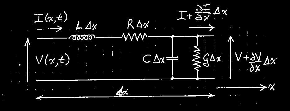
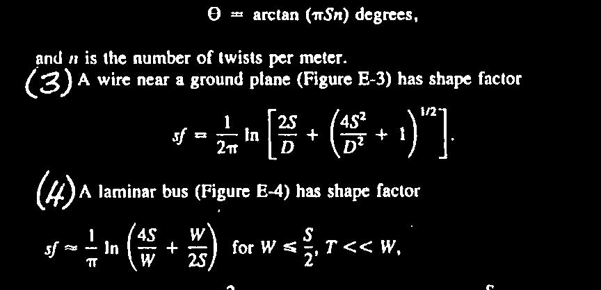
18 B/C/D. Transmission line effects 35 Lecture topics B: Transmission lines (Z 0, velocity, lossless, lossy) 1. Transmission line theory Characteristic impedance Z 0 Attennuation, dispersion, velocity 2. Z 0 calculations 3. Lossless line Distortionless transmission Shape factor 4. Z 0 for practical geometries 5. Effects of loss Distortion 36 18
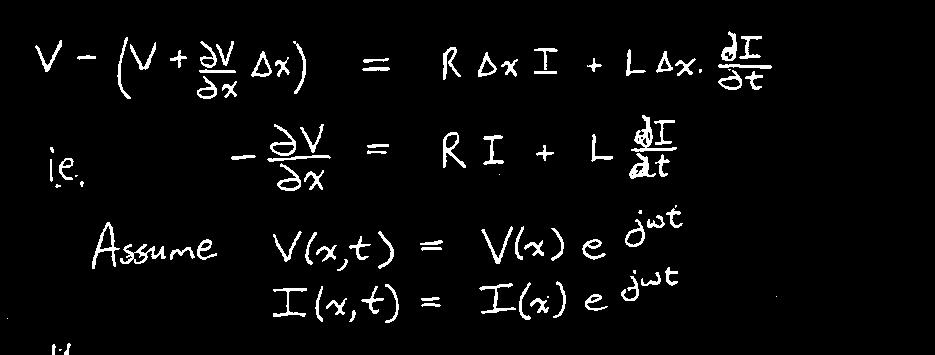


19 1. Transmission line theory 37 Summary 38 19
20 2. Z 0 calculations Need L, C Also gives β, v Easiest geometry is coaxial line (radial symmetry) (a) Dielectric: C/unit length (b) Leakage conductance: G/unit length (c) Inductance: L/unit length Lossless lines 40 20


21 41 4. Practical Z
22
23 5. Lossy lines 45 Lecture topics C: Transmission lines Transmission line reflections 1. Reflection coefficients 2. Basic cases: Matched and open circuit 3. Generalized mismatches Source and load 4. Bounce chart/lattice diagram 5. Rfl Reflections from discontinuitiesi ii 46 23

 Load R L = Z 0 (above)")
 R S =")

24 1. Reflection Coefficient significant cases: Γ VL = (R L -Z 0 )/ (R L +Z 0 ) Load R L = Z 0 (above) Γ VL = 0 Open circuit load: R S = Z 0 (Γ VL = 1) R S = 0 (Γ VS = -1) Short circuit load R L = 0, Γ VL =


 R S << Z")
25 49 3. Mismatched load &/or source 1 volt pulse, Z 0 = 78Ω Consider R L = 78Ω cases first, then vary R L for (a) R S =Z 0 (b) R S << Z 0 (c) R S >> Z


26 4. Bounce chart (lattice diagram) Calculate reflection coefficients Distance / time diagram Transfer data to waveform plots Example: Open circuit line Discontinuities 52 26


27
28 Summary 55 Lecture topics D: Transmission lines Crosstalk 1. Inductive and capacitive coupling 2. Forward and backward noise 3. Far end and near end noise 4. Incremental model and formulae 5. Crosstalk examples 6. Capacitive crosstalk systems 7. No ground plane 56 28


29 1. Inductive and capacitive coupling Incremental line model Crosstalk polarities Forward & backward noise 3. Near end & far end 58 29

30 4. Theory: line segment 59 Far end overview 60 30

31 Backward wave model 61 Near end pulse shape 62 31
32 Near End Saturation Pulse crosstalk noise examples Drive pulse: 0.5 volt, t width =20ns, t rise =t fall =1ns Forward noise: matched Backward: matched 32
33 Not matched Forward( Far end) Backward (Near end) Ground coupled crosstalk 66 33
34 7. Mutual capacitances Even/odd modes 67 Microstrip Lecture topics E: Electromagnetic Modeling Transmission line 68 34

35 3. Electromagnetic Modeling (Fang) Finite element mesh 69 a. Current pulse excitation of line 70 Electric field distribution on line 35


36 b. Chamfered right angle bend Pulse after reflection from corner 71 c. Orthogonal line crosstalk 72 36


37 Lecture topics F: Electromagnetic Compatibility 1. Antennas 2. Emissions 3. Susceptibility EMI/EMC Models: Loop/Dipole Antennas 74 37
38 L I 1 d I 2 L R s d H n E t R L 75 Electromagnetic compatibility/interference m 2. EMI/EMC Models: Emissions At far field distance r ( λ=c/f) from the line of length L and area A = L.d, the radiated electric field strength is E = E D + E CM where E D due to the differential current I D is E D = x f 2 A I D /r V/m and E CM due to the common mode current I CM is (for L λ) E CM = 4π x 10-7 f 2 L I CM /r V/m where I D = (I 1 + I 2 )/2 and I CM = (I 1 -I 2 )/2. Common mode currents are ideally zero, but small values can lead to CM dominance over differential. For the differential current, the maximum value can be taken to be the supply current, but the user must specify a non-ideal common mode estimate. For digital systems, use f = 2π/t r. For other geometries, other expressions for A are valid. There are many different standards for EM radiation limits, but for guidance the EU limit is E 100μV/m at r = 10m (class A) or 3m (class B)
39 EMI/EMC Models: Susceptibility jwμ o L d H n + V s - R L R s -jwcld E t V L + - odels Susceptibility For the line shown, with capacitance C per unit length, e.g. C = π ε r ε 0 /ln(d/r w ) for parallel wires, the induced voltages are V S = -jω [R L R S / (R L + R S )] [Ld] [C - (μ 0 /η 0 )/R L ] V L = -jω [R L R S / (R L + R S )] [Ld] [C + (μ 0 /η 0 )/R S ] where E = E t = η 0 H n, and η 0 = 120π = 377Ω. As an example of an EU standard, d the device must function in a field of E = 3V/m
ECE414/514 Electronics Packaging Spring 2012 Lecture 5 Electrical C: Transmission lines (Transmission line reflections) Lecture topics
 Lecture topics") ECE414/514 Electronics Packaging Spring 2012 Lecture 5 Electrical C: Transmission lines (Transmission line reflections) James E. Morris Dept of Electrical & Computer Engineering Portland State University
ECE414/514 Electronics Packaging Spring 2012 Lecture 5 Electrical C: Transmission lines (Transmission line reflections) James E. Morris Dept of Electrical & Computer Engineering Portland State University
ECE414/514 Electronics Packaging Spring 2012 Lecture 6 Electrical D: Transmission lines (Crosstalk) Lecture topics
 Lecture topics") ECE414/514 Electronics Packaging Spring 2012 Lecture 6 Electrical D: Transmission lines (Crosstalk) James E. Morris Dept of Electrical & Computer Engineering Portland State University 1 Lecture topics
ECE414/514 Electronics Packaging Spring 2012 Lecture 6 Electrical D: Transmission lines (Crosstalk) James E. Morris Dept of Electrical & Computer Engineering Portland State University 1 Lecture topics
ESE 570: Digital Integrated Circuits and VLSI Fundamentals
 ESE 570: Digital Integrated Circuits and VLSI Fundamentals Lec 24: April 19, 2018 Crosstalk and Wiring, Transmission Lines Lecture Outline! Crosstalk! Repeaters in Wiring! Transmission Lines " Where transmission
Transmission Lines. Plane wave propagating in air Y unguided wave propagation. Transmission lines / waveguides Y. guided wave propagation
 Transmission Lines Transmission lines and waveguides may be defined as devices used to guide energy from one point to another (from a source to a load). Transmission lines can consist of a set of conductors,
! Crosstalk. ! Repeaters in Wiring. ! Transmission Lines. " Where transmission lines arise? " Lossless Transmission Line.
 ESE 570: Digital Integrated Circuits and VLSI Fundamentals Lec 24: April 19, 2018 Crosstalk and Wiring, Transmission Lines Lecture Outline! Crosstalk! Repeaters in Wiring! Transmission Lines " Where transmission
SCSI Connector and Cable Modeling from TDR Measurements
 SCSI Connector and Cable Modeling from TDR Measurements Dima Smolyansky TDA Systems, Inc. http://www.tdasystems.com Presented at SCSI Signal Modeling Study Group Rochester, MN, December 1, 1999 Outline
Non-Sinusoidal Waves on (Mostly Lossless)Transmission Lines
Transmission Lines") Non-Sinusoidal Waves on (Mostly Lossless)Transmission Lines Don Estreich Salazar 21C Adjunct Professor Engineering Science October 212 https://www.iol.unh.edu/services/testing/sas/tools.php 1 Outline of
Non-Sinusoidal Waves on (Mostly Lossless)Transmission Lines Don Estreich Salazar 21C Adjunct Professor Engineering Science October 212 https://www.iol.unh.edu/services/testing/sas/tools.php 1 Outline of
ECE 6340 Intermediate EM Waves. Fall Prof. David R. Jackson Dept. of ECE. Notes 7
 ECE 634 Intermediate EM Waves Fall 16 Prof. David R. Jackson Dept. of ECE Notes 7 1 TEM Transmission Line conductors 4 parameters C capacitance/length [F/m] L inductance/length [H/m] R resistance/length
Kimmo Silvonen, Transmission lines, ver
 Kimmo Silvonen, Transmission lines, ver. 13.10.2008 1 1 Basic Theory The increasing operating and clock frequencies require transmission line theory to be considered more and more often! 1.1 Some practical
ECE 497 JS Lecture -03 Transmission Lines
 ECE 497 JS Lecture -03 Transmission Lines Spring 2004 Jose E. Schutt-Aine Electrical & Computer Engineering University of Illinois jose@emlab.uiuc.edu 1 MAXWELL S EQUATIONS B E = t Faraday s Law of Induction
Name. Section. Short Answer Questions. 1. (20 Pts) 2. (10 Pts) 3. (5 Pts) 4. (10 Pts) 5. (10 Pts) Regular Questions. 6. (25 Pts) 7.
 2. (10 Pts) 3. (5 Pts) 4. (10 Pts) 5. (10 Pts) Regular Questions. 6. (25 Pts) 7.") Name Section Short Answer Questions 1. (20 Pts) 2. (10 Pts) 3. (5 Pts). (10 Pts) 5. (10 Pts) Regular Questions 6. (25 Pts) 7. (20 Pts) Notes: 1. Please read over all questions before you begin your work.
Name Section Short Answer Questions 1. (20 Pts) 2. (10 Pts) 3. (5 Pts). (10 Pts) 5. (10 Pts) Regular Questions 6. (25 Pts) 7. (20 Pts) Notes: 1. Please read over all questions before you begin your work.
ELECTROMAGNETIC FIELDS AND WAVES
 ELECTROMAGNETIC FIELDS AND WAVES MAGDY F. ISKANDER Professor of Electrical Engineering University of Utah Englewood Cliffs, New Jersey 07632 CONTENTS PREFACE VECTOR ANALYSIS AND MAXWELL'S EQUATIONS IN
Module 2 : Transmission Lines. Lecture 1 : Transmission Lines in Practice. Objectives. In this course you will learn the following
 Objectives In this course you will learn the following Point 1 Point 2 Point 3 Point 4 Point 5 Point 6 Point 7 Point 8 Point 9 Point 10 Point 11 Point 12 Various Types Of Transmission Line Explanation:
The Cooper Union Department of Electrical Engineering ECE135 Engineering Electromagnetics Exam II April 12, Z T E = η/ cos θ, Z T M = η cos θ
 The Cooper Union Department of Electrical Engineering ECE135 Engineering Electromagnetics Exam II April 12, 2012 Time: 2 hours. Closed book, closed notes. Calculator provided. For oblique incidence of
INTRODUCTION TO TRANSMISSION LINES DR. FARID FARAHMAND FALL 2012
 INTRODUCTION TO TRANSMISSION LINES DR. FARID FARAHMAND FALL 2012 http://www.empowermentresources.com/stop_cointelpro/electromagnetic_warfare.htm RF Design In RF circuits RF energy has to be transported
Transmission-Line Essentials for Digital Electronics
 C H A P T E R 6 Transmission-Line Essentials for Digital Electronics In Chapter 3 we alluded to the fact that lumped circuit theory is based on lowfrequency approximations resulting from the neglect of
EE141-Spring 2008 Digital Integrated Circuits EE141. Announcements EECS141 EE141. Lecture 24: Wires
 EE141-Spring 2008 Digital Integrated Circuits Lecture 24: Wires 1 Announcements Hw 8 posted last graded homework Project phase II feedback to be expected anytime 2 Material Last Lecture: Wire capacitance
INSTITUTE OF AERONAUTICAL ENGINEERING Dundigal, Hyderabad Electronics and Communicaton Engineering
 INSTITUTE OF AERONAUTICAL ENGINEERING Dundigal, Hyderabad - 00 04 Electronics and Communicaton Engineering Question Bank Course Name : Electromagnetic Theory and Transmission Lines (EMTL) Course Code :
UNIVERSITY OF BOLTON. SCHOOL OF ENGINEERING, SPORTS and SCIENCES BENG (HONS) ELECTRICAL & ELECTRONICS ENGINEERING EXAMINATION SEMESTER /2018
 ELECTRICAL & ELECTRONICS ENGINEERING EXAMINATION SEMESTER /2018") ENG018 SCHOOL OF ENGINEERING, SPORTS and SCIENCES BENG (HONS) ELECTRICAL & ELECTRONICS ENGINEERING MODULE NO: EEE6002 Date: 17 January 2018 Time: 2.00 4.00 INSTRUCTIONS TO CANDIDATES: There are six questions.
ENG018 SCHOOL OF ENGINEERING, SPORTS and SCIENCES BENG (HONS) ELECTRICAL & ELECTRONICS ENGINEERING MODULE NO: EEE6002 Date: 17 January 2018 Time: 2.00 4.00 INSTRUCTIONS TO CANDIDATES: There are six questions.
PHYSICS 2B FINAL EXAM ANSWERS WINTER QUARTER 2010 PROF. HIRSCH MARCH 18, 2010 Problems 1, 2 P 1 P 2
 Problems 1, 2 P 1 P 1 P 2 The figure shows a non-conducting spherical shell of inner radius and outer radius 2 (i.e. radial thickness ) with charge uniformly distributed throughout its volume. Prob 1:
Spectral Domain Analysis of Open Planar Transmission Lines
 Mikrotalasna revija Novembar 4. Spectral Domain Analysis of Open Planar Transmission Lines Ján Zehentner, Jan Mrkvica, Jan Macháč Abstract The paper presents a new code calculating the basic characteristics
Engineering Electromagnetics
 Nathan Ida Engineering Electromagnetics With 821 Illustrations Springer Contents Preface vu Vector Algebra 1 1.1 Introduction 1 1.2 Scalars and Vectors 2 1.3 Products of Vectors 13 1.4 Definition of Fields
KINGS COLLEGE OF ENGINEERING DEPARTMENT OF ELECTRONICS AND COMMUNICATION ENGINEERING QUESTION BANK
 KINGS COLLEGE OF ENGINEERING DEPARTMENT OF ELECTRONICS AND COMMUNICATION ENGINEERING QUESTION BANK SUB.NAME : ELECTROMAGNETIC FIELDS SUBJECT CODE : EC 2253 YEAR / SEMESTER : II / IV UNIT- I - STATIC ELECTRIC
EELE 3332 Electromagnetic II Chapter 11. Transmission Lines. Islamic University of Gaza Electrical Engineering Department Dr.
 EEE 333 Electromagnetic II Chapter 11 Transmission ines Islamic University of Gaza Electrical Engineering Department Dr. Talal Skaik 1 1 11.1 Introduction Wave propagation in unbounded media is used in
ECE 497 JS Lecture - 18 Noise in Digital Circuits
 ECE 497 JS Lecture - 18 Noise in Digital Circuits Spring 2004 Jose E. Schutt-Aine Electrical & Computer Engineering University of Illinois jose@emlab.uiuc.edu 1 Announcements Thursday April 15 th Speaker:
PRACTICE NO. PD-AP-1309 PREFERRED PAGE 1 OF 5 RELIABILITY PRACTICES ANALYSIS OF RADIATED EMI FROM ESD EVENTS CAUSED BY SPACE CHARGING
 PREFERRED PAGE 1 OF 5 RELIABILITY PRACTICES ANALYSIS OF RADIATED EMI FROM ESD EVENTS Practice: Modeling is utilized for the analysis of conducted and radiated electromagnetic interference (EMI) caused
Equivalent Circuit Model Extraction for Interconnects in 3D ICs
 Equivalent Circuit Model Extraction for Interconnects in 3D ICs A. Ege Engin Assistant Professor, Department of ECE, San Diego State University Email: aengin@mail.sdsu.edu ASP-DAC, Jan. 23, 213 Outline
AC Circuits. The Capacitor
 The Capacitor Two conductors in close proximity (and electrically isolated from one another) form a capacitor. An electric field is produced by charge differences between the conductors. The capacitance
ECE357H1S ELECTROMAGNETIC FIELDS TERM TEST 1. 8 February 2016, 19:00 20:00. Examiner: Prof. Sean V. Hum
 UNIVERSITY OF TORONTO FACULTY OF APPLIED SCIENCE AND ENGINEERING The Edward S. Rogers Sr. Department of Electrical and Computer Engineering ECE57HS ELECTROMAGNETIC FIELDS TERM TEST 8 February 6, 9:00 :00
SRAM System Design Guidelines
 Introduction This application note examines some of the important system design considerations an engineer should keep in mind when designing with Cypress SRAMs. It is important to note that while they
STUDY OF LOSS EFFECT OF TRANSMISSION LINES AND VALIDITY OF A SPICE MODEL IN ELECTROMAG- NETIC TOPOLOGY
 Progress In Electromagnetics Research, PIER 90, 89 103, 2009 STUDY OF LOSS EFFECT OF TRANSMISSION LINES AND VALIDITY OF A SPICE MODEL IN ELECTROMAG- NETIC TOPOLOGY H. Xie, J. Wang, R. Fan, andy. Liu Department
Self-Inductance. Φ i. Self-induction. = (if flux Φ 1 through 1 loop. Tm Vs A A. Lecture 11-1
 Lecture - Self-Inductance As current i through coil increases, magnetic flux through itself increases. This in turn induces back emf in the coil itself When current i is decreasing, emf is induced again
Effects from the Thin Metallic Substrate Sandwiched in Planar Multilayer Microstrip Lines
 Progress In Electromagnetics Research Symposium 2006, Cambridge, USA, March 26-29 115 Effects from the Thin Metallic Substrate Sandwiched in Planar Multilayer Microstrip Lines L. Zhang and J. M. Song Iowa
DIRECTIONAL COUPLERS
 DIRECTIONAL COUPLERS Ing. rvargas@inictel.gob.pe INICTEL Abstract This paper analyzes two types of Directional Couplers. First, magnetic coupling between a transmission line and a secondary circuit is
Switched Mode Power Conversion
 Inductors Devices for Efficient Power Conversion Switches Inductors Transformers Capacitors Inductors Inductors Store Energy Inductors Store Energy in a Magnetic Field In Power Converters Energy Storage
ELECTROMAGNETISM. Second Edition. I. S. Grant W. R. Phillips. John Wiley & Sons. Department of Physics University of Manchester
 ELECTROMAGNETISM Second Edition I. S. Grant W. R. Phillips Department of Physics University of Manchester John Wiley & Sons CHICHESTER NEW YORK BRISBANE TORONTO SINGAPORE Flow diagram inside front cover
Electromagnetics in COMSOL Multiphysics is extended by add-on Modules
 AC/DC Module Electromagnetics in COMSOL Multiphysics is extended by add-on Modules 1) Start Here 2) Add Modules based upon your needs 3) Additional Modules extend the physics you can address 4) Interface
ECE 451 Transmission Lines & Packaging
 Transmission Lines & Packaging Jose E. Schutt-Aine Electrical & Computer Engineering University of Illinois jose@emlab.uiuc.edu 1 Radio Spectrum Bands The use of letters to designate bands has long ago
Lecture 11 - AC Power
 - AC Power 11/17/2015 Reading: Chapter 11 1 Outline Instantaneous power Complex power Average (real) power Reactive power Apparent power Maximum power transfer Power factor correction 2 Power in AC Circuits
444 Index Boundary condition at transmission line short circuit, 234 for normal component of B, 170, 180 for normal component of D, 169, 180 for tange
 Index A. see Magnetic vector potential. Acceptor, 193 Addition of complex numbers, 19 of vectors, 3, 4 Admittance characteristic, 251 input, 211 line, 251 Ampere, definition of, 427 Ampere s circuital
Electromagnetic Modeling and Signal Integrity Simulation of Power/Ground Networks in High Speed Digital Packages and Printed Circuit Boards
 Electromagnetic Modeling and Signal Integrity Simulation of Power/Ground Networks in High Speed Digital Packages and Printed Circuit Boards Frank Y. Yuan Viewlogic Systems Group, Inc. 385 Del Norte Road
Lecture 2 - Transmission Line Theory
 Lecture 2 - Transmission Line Theory Microwave Active Circuit Analysis and Design Clive Poole and Izzat Darwazeh Academic Press Inc. Poole-Darwazeh 2015 Lecture 2 - Transmission Line Theory Slide1 of 54
Interconnects. Wire Resistance Wire Capacitance Wire RC Delay Crosstalk Wire Engineering Repeaters. ECE 261 James Morizio 1
 Interconnects Wire Resistance Wire Capacitance Wire RC Delay Crosstalk Wire Engineering Repeaters ECE 261 James Morizio 1 Introduction Chips are mostly made of wires called interconnect In stick diagram,
Introduction. HFSS 3D EM Analysis S-parameter. Q3D R/L/C/G Extraction Model. magnitude [db] Frequency [GHz] S11 S21 -30
![Introduction. HFSS 3D EM Analysis S-parameter. Q3D R/L/C/G Extraction Model. magnitude [db] Frequency [GHz] S11 S21 -30](/thumbs/81/83311716.jpg "Introduction. HFSS 3D EM Analysis S-parameter. Q3D R/L/C/G Extraction Model. magnitude [db] Frequency [GHz] S11 S21 -30") ANSOFT Q3D TRANING Introduction HFSS 3D EM Analysis S-parameter Q3D R/L/C/G Extraction Model 0-5 -10 magnitude [db] -15-20 -25-30 S11 S21-35 0 1 2 3 4 5 6 7 8 9 10 Frequency [GHz] Quasi-static or full-wave
ANSOFT Q3D TRANING Introduction HFSS 3D EM Analysis S-parameter Q3D R/L/C/G Extraction Model 0-5 -10 magnitude [db] -15-20 -25-30 S11 S21-35 0 1 2 3 4 5 6 7 8 9 10 Frequency [GHz] Quasi-static or full-wave
A Time Domain Approach to Power Integrity for Printed Circuit Boards
 A Time Domain Approach to Power Integrity for Printed Circuit Boards N. L. Mattey 1*, G. Edwards 2 and R. J. Hood 2 1 Electrical & Optical Systems Research Division, Faculty of Engineering, University
TRANSFORMERS B O O K P G
 TRANSFORMERS B O O K P G. 4 4 4-449 REVIEW The RMS equivalent current is defined as the dc that will provide the same power in the resistor as the ac does on average P average = I 2 RMS R = 1 2 I 0 2 R=
4.4 Microstrip dipole
 4.4 Microstrip dipole Basic theory Microstrip antennas are frequently used in today's wireless communication systems. Thanks to their low profile, they can be mounted to the walls of buildings, to the
TC 412 Microwave Communications. Lecture 6 Transmission lines problems and microstrip lines
 TC 412 Microwave Communications Lecture 6 Transmission lines problems and microstrip lines RS 1 Review Input impedance for finite length line Quarter wavelength line Half wavelength line Smith chart A
The Wire EE141. Microelettronica
 The Wire 1 Interconnect Impact on Chip 2 Example: a Bus Network transmitters receivers schematics physical 3 Wire Models All-inclusive model Capacitance-only 4 Impact of Interconnect Parasitics Interconnect
Book Page cgrahamphysics.com Transformers
 Book Page 444-449 Transformers Review The RMS equivalent current is defined as the dc that will provide the same power in the resistor as the ac does on average P average = I 2 RMS R = 1 2 I 0 2 R= V RMS
LECTURE 6 MUTUAL INDUCTANCE
 ECE 330 POWER CIRCUITS AND ELECTROMECHANICS LECTURE 6 MUTUAL INDUCTANCE Acknowledgment-These handouts and lecture notes given in class are based on material from Prof. Peter Sauer s ECE 330 lecture notes.
and Ee = E ; 0 they are separated by a dielectric material having u = io-s S/m, µ, = µ, 0
 602 CHAPTER 11 TRANSMISSION LINES 11.10 Two identical pulses each of magnitude 12 V and width 2 µs are incident at t = 0 on a lossless transmission line of length 400 m terminated with a load. If the two
ECE357H1F ELECTROMAGNETIC FIELDS FINAL EXAM. 28 April Examiner: Prof. Sean V. Hum. Duration: hours
 UNIVERSITY OF TORONTO FACULTY OF APPLIED SCIENCE AND ENGINEERING The Edward S. Rogers Sr. Department of Electrical and Computer Engineering ECE357H1F ELECTROMAGNETIC FIELDS FINAL EXAM 28 April 15 Examiner:
Chapter 30 Inductance and Electromagnetic Oscillations
 Chapter 30 Inductance and Electromagnetic Oscillations Units of Chapter 30 30.1 Mutual Inductance: 1 30.2 Self-Inductance: 2, 3, & 4 30.3 Energy Stored in a Magnetic Field: 5, 6, & 7 30.4 LR Circuit: 8,
ECE 497 JS Lecture - 13 Projects
 ECE 497 JS Lecture - 13 Projects Spring 2004 Jose E. Schutt-Aine Electrical & Computer Engineering University of Illinois jose@emlab.uiuc.edu 1 ECE 497 JS - Projects All projects should be accompanied
Antennas and Propagation. Chapter 2: Basic Electromagnetic Analysis
 Antennas and Propagation : Basic Electromagnetic Analysis Outline Vector Potentials, Wave Equation Far-field Radiation Duality/Reciprocity Transmission Lines Antennas and Propagation Slide 2 Antenna Theory
Transmission Lines. Author: Michael Leddige
 Transmission Lines Author: Michael Leddige 1 Contents PCB Transmission line structures Equivalent Circuits and Key Parameters Lossless Transmission Line Analysis Driving Reflections Systems Reactive Elements
About Exam 3. When and where
 When and where About Exam 3 Tuesday Nov 27th 5:30-7:00 pm (same location as Midterms 1 and 2) Format Closed book One 8x11 formula sheet allowed, must be self prepared, no photo copying/download-printing
Basics of Network Theory (Part-I)
") Basics of Network Theory (Part-I) 1. One coulomb charge is equal to the charge on (a) 6.24 x 10 18 electrons (b) 6.24 x 10 24 electrons (c) 6.24 x 10 18 atoms (d) none of the above 2. The correct relation
Basics of Network Theory (Part-I) 1. One coulomb charge is equal to the charge on (a) 6.24 x 10 18 electrons (b) 6.24 x 10 24 electrons (c) 6.24 x 10 18 atoms (d) none of the above 2. The correct relation
Electromagnetic Compatibility in Industrial Equipment
 Electromagnetic Compatibility in Industrial Equipment Giorgio Spiazzi Department of Electronics & Informatics University of Padova - ITALY Fundamental Definitions Electromagnetic Compatibility The capability
Understanding EMC Basics
 1of 7 series Webinar #1 of 3, February 27, 2013 EM field theory, and 3 types of EM analysis Webinar Sponsored by: EurIng CEng, FIET, Senior MIEEE, ACGI AR provides EMC solutions with our high power RF/Microwave
Lecture 23: Negative Resistance Osc, Differential Osc, and VCOs
 EECS 142 Lecture 23: Negative Resistance Osc, Differential Osc, and VCOs Prof. Ali M. Niknejad University of California, Berkeley Copyright c 2005 by Ali M. Niknejad A. M. Niknejad University of California,
ECEN720: High-Speed Links Circuits and Systems Spring 2017
 ECEN70: High-Speed Links Circuits and Systems Spring 07 Lecture : Channel Components, Wires, & Transmission Lines Sam Palermo Analog & Mixed-Signal Center Texas A&M University Announcements Lab Lab begins
EECS 117 Lecture 3: Transmission Line Junctions / Time Harmonic Excitation
 EECS 117 Lecture 3: Transmission Line Junctions / Time Harmonic Excitation Prof. Niknejad University of California, Berkeley University of California, Berkeley EECS 117 Lecture 3 p. 1/23 Transmission Line
Basics of Network Theory (Part-I)
") Basics of Network Theory (PartI). A square waveform as shown in figure is applied across mh ideal inductor. The current through the inductor is a. wave of peak amplitude. V 0 0.5 t (m sec) [Gate 987: Marks]
Basics of Network Theory (PartI). A square waveform as shown in figure is applied across mh ideal inductor. The current through the inductor is a. wave of peak amplitude. V 0 0.5 t (m sec) [Gate 987: Marks]
ECE 546 Lecture 13 Scattering Parameters
 ECE 546 Lecture 3 Scattering Parameters Spring 08 Jose E. Schutt-Aine Electrical & Computer Engineering University of Illinois jesa@illinois.edu ECE 546 Jose Schutt Aine Transfer Function Representation
The Wire. Digital Integrated Circuits A Design Perspective. Jan M. Rabaey Anantha Chandrakasan Borivoje Nikolic. July 30, 2002
 Digital Integrated Circuits A Design Perspective Jan M. Rabaey Anantha Chandrakasan Borivoje Nikolic The Wire July 30, 2002 1 The Wire transmitters receivers schematics physical 2 Interconnect Impact on
1 Chapter 8 Maxwell s Equations
 Electromagnetic Waves ECEN 3410 Prof. Wagner Final Review Questions 1 Chapter 8 Maxwell s Equations 1. Describe the integral form of charge conservation within a volume V through a surface S, and give
Magnetic Force on a Moving Charge
 Magnetic Force on a Moving Charge Electric charges moving in a magnetic field experience a force due to the magnetic field. Given a charge Q moving with velocity u in a magnetic flux density B, the vector
Experiment 06 - Extraction of Transmission Line Parameters
 ECE 451 Automated Microwave Measurements Laboratory Experiment 06 - Extraction of Transmission Line Parameters 1 Introduction With the increase in both speed and complexity of mordern circuits, modeling
Electromagnetic Oscillations and Alternating Current. 1. Electromagnetic oscillations and LC circuit 2. Alternating Current 3.
 Electromagnetic Oscillations and Alternating Current 1. Electromagnetic oscillations and LC circuit 2. Alternating Current 3. RLC circuit in AC 1 RL and RC circuits RL RC Charging Discharging I = emf R
Determining Characteristic Impedance and Velocity of Propagation by Measuring the Distributed Capacitance and Inductance of a Line
 Exercise 2-1 Determining Characteristic Impedance and Velocity EXERCISE OBJECTIVES Upon completion of this exercise, you will know how to measure the distributed capacitance and distributed inductance
Topic 5: Transmission Lines
 Topic 5: Transmission Lines Profs. Javier Ramos & Eduardo Morgado Academic year.13-.14 Concepts in this Chapter Mathematical Propagation Model for a guided transmission line Primary Parameters Secondary
L K K K K P P1 N GU EU GV EV GW EW GU GVGW GB E LABEL H H
 Three Phase Converter + Three Phase Inverter + Brake A ( PLACES) G J L L L P P1 N GU EU GV EV GW EW GU GVGW GB E Q C R D LABEL D U B R S T S V 3 MAIN TERMINAL X P P1 Outline Drawing and Circuit Diagram
ECEN689: Special Topics in High-Speed Links Circuits and Systems Spring 2012
 ECEN689: Special Topics in High-Speed Links Circuits and Systems Spring 0 Lecture : Channel Components, Wires, & Transmission Lines Sam Palermo Analog & Mixed-Signal Center Texas A&M University Announcements
ECE 598 JS Lecture 06 Multiconductors
 ECE 598 JS Lecture 06 Multiconductors Spring 2012 Jose E. Schutt-Aine Electrical & Computer Engineering University of Illinois jesa@illinois.edu 1 TELGRAPHER S EQUATION FOR N COUPLED TRANSMISSION LINES
ECE 497 JS Lecture -07 Planar Transmission Lines
 ECE 497 JS Lecture -07 Planar Transmission Lines Spring 2004 Jose E. Schutt-Aine Electrical & Computer Engineering University of Illinois jose@emlab.uiuc.edu 1 Microstrip ε Z o w/h < 3.3 2 119.9 h h =
Wave Phenomena Physics 15c. Lecture 8 LC Transmission Line Wave Reflection
 Wave Phenomena Physics 15c Lecture 8 LC Transmission Line Wave Reflection Midterm Exam #1 Midterm #1 has been graded Class average = 80.4 Standard deviation = 14.6 Your exam will be returned in the section
TECHNO INDIA BATANAGAR
 TECHNO INDIA BATANAGAR ( DEPARTMENT OF ELECTRONICS & COMMUNICATION ENGINEERING) QUESTION BANK- 2018 1.Vector Calculus Assistant Professor 9432183958.mukherjee@tib.edu.in 1. When the operator operates on
T C MEASURED POINT G1 E1 E2 G2 W - (4 PLACES) G2 E2 E1 G1
 G2 E2 E1 G1") CMDU-3KA Powerex, Inc., Hillis Street, Youngwood, Pennsylvania 15697-1 (7) 95-77 Dual IGBTMOD KA-Series Module Amperes/17 Volts B F A G T C MEASURED POINT M C L T - ( TYP.) N R Z CE1 E C1 C E AA S - (3
CMDU-3KA Powerex, Inc., Hillis Street, Youngwood, Pennsylvania 15697-1 (7) 95-77 Dual IGBTMOD KA-Series Module Amperes/17 Volts B F A G T C MEASURED POINT M C L T - ( TYP.) N R Z CE1 E C1 C E AA S - (3
11. AC Circuit Power Analysis
 . AC Circuit Power Analysis Often an integral part of circuit analysis is the determination of either power delivered or power absorbed (or both). In this chapter First, we begin by considering instantaneous
Lecture Outline. Shorted line (Z L = 0) Open circuit line (Z L = ) Matched line (Z L = Z 0 ) 9/28/2017. EE 4347 Applied Electromagnetics.
 Open circuit line (Z L = ) Matched line (Z L = Z 0 ) 9/28/2017. EE 4347 Applied Electromagnetics.") 9/8/17 Course Instructor Dr. Raymond C. Rumpf Office: A 337 Phone: (915) 747 6958 E Mail: rcrumpf@utep.edu EE 4347 Applied Electromagnetics Topic 4b Transmission ine Behavior Transmission These ine notes
9/8/17 Course Instructor Dr. Raymond C. Rumpf Office: A 337 Phone: (915) 747 6958 E Mail: rcrumpf@utep.edu EE 4347 Applied Electromagnetics Topic 4b Transmission ine Behavior Transmission These ine notes
Introduction to RF Design. RF Electronics Spring, 2016 Robert R. Krchnavek Rowan University
 Introduction to RF Design RF Electronics Spring, 2016 Robert R. Krchnavek Rowan University Objectives Understand why RF design is different from lowfrequency design. Develop RF models of passive components.
MMIX4B12N300 V CES = 3000V. = 11A V CE(sat) 3.2V. High Voltage, High Gain BIMOSFET TM Monolithic Bipolar MOS Transistor
 3.2V. High Voltage, High Gain BIMOSFET TM Monolithic Bipolar MOS Transistor") High Voltage, High Gain BIMOSFET TM Monolithic Bipolar MOS Transistor Preliminary Technical Information V CES = 3V 11 = 11A V CE(sat) 3.2V C1 C2 (Electrically Isolated Tab) G1 E1C3 G2 E2C G3 G E3E C1 C2
High Voltage, High Gain BIMOSFET TM Monolithic Bipolar MOS Transistor Preliminary Technical Information V CES = 3V 11 = 11A V CE(sat) 3.2V C1 C2 (Electrically Isolated Tab) G1 E1C3 G2 E2C G3 G E3E C1 C2
Conventional Paper-I Part A. 1. (a) Define intrinsic wave impedance for a medium and derive the equation for intrinsic vy
 Define intrinsic wave impedance for a medium and derive the equation for intrinsic vy") EE-Conventional Paper-I IES-01 www.gateforum.com Conventional Paper-I-01 Part A 1. (a) Define intrinsic wave impedance for a medium and derive the equation for intrinsic vy impedance for a lossy dielectric
EE-Conventional Paper-I IES-01 www.gateforum.com Conventional Paper-I-01 Part A 1. (a) Define intrinsic wave impedance for a medium and derive the equation for intrinsic vy impedance for a lossy dielectric
EECS 117. Lecture 22: Poynting s Theorem and Normal Incidence. Prof. Niknejad. University of California, Berkeley
 University of California, Berkeley EECS 117 Lecture 22 p. 1/2 EECS 117 Lecture 22: Poynting s Theorem and Normal Incidence Prof. Niknejad University of California, Berkeley University of California, Berkeley
Engineering Electromagnetic Fields and Waves
 CARL T. A. JOHNK Professor of Electrical Engineering University of Colorado, Boulder Engineering Electromagnetic Fields and Waves JOHN WILEY & SONS New York Chichester Brisbane Toronto Singapore CHAPTER
ANTENNAS and MICROWAVES ENGINEERING (650427)
") Philadelphia University Faculty of Engineering Communication and Electronics Engineering ANTENNAS and MICROWAVES ENGINEERING (65427) Part 2 Dr. Omar R Daoud 1 General Considerations It is a two-port network
Philadelphia University Faculty of Engineering Communication and Electronics Engineering ANTENNAS and MICROWAVES ENGINEERING (65427) Part 2 Dr. Omar R Daoud 1 General Considerations It is a two-port network
PHY3128 / PHYM203 (Electronics / Instrumentation) Transmission Lines
 Transmission Lines") Transmission Lines Introduction A transmission line guides energy from one place to another. Optical fibres, waveguides, telephone lines and power cables are all electromagnetic transmission lines. are
Transmission Lines Introduction A transmission line guides energy from one place to another. Optical fibres, waveguides, telephone lines and power cables are all electromagnetic transmission lines. are
Physics 6B Summer 2007 Final
 Physics 6B Summer 2007 Final Question 1 An electron passes through two rectangular regions that contain uniform magnetic fields, B 1 and B 2. The field B 1 is stronger than the field B 2. Each field fills
Topics to be Covered. capacitance inductance transmission lines
 Topics to be Covered Circuit Elements Switching Characteristics Power Dissipation Conductor Sizes Charge Sharing Design Margins Yield resistance capacitance inductance transmission lines Resistance of
MCE380: Measurements and Instrumentation Lab. Chapter 5: Electromechanical Transducers
 MCE380: Measurements and Instrumentation Lab Chapter 5: Electromechanical Transducers Part I Topics: Transducers and Impedance Magnetic Electromechanical Coupling Reference: Holman, CH 4. Cleveland State
TECHNICAL REPORT: CVEL Maximum Radiated Emission Calculator: I/O Coupling Algorithm. Chentian Zhu and Dr. Todd Hubing. Clemson University
 TECHNICAL REPORT: CVEL-13-045 Maximum Radiated Emission Calculator: I/O Coupling Algorithm Chentian Zhu and Dr. Todd Hubing Clemson University August 4, 013 Table of Contents Abstract... 3 1. Introduction...
About Exam 3. When and where Monday Nov. 24 th 5:30-7:00 pm
 About Exam 3 When and where Monday Nov. 24 th 5:30-7:00 pm 2650, 3650 Humanities (same as exam 1 and 2) Format Closed book One 8x11 formula sheet allowed, must be self prepared, no photo copy of solutions,
RECENT ADVANCES in NETWORKING, VLSI and SIGNAL PROCESSING
 Optimization of Reflection Issues in High Speed Printed Circuit Boards ROHITA JAGDALE, A.VENU GOPAL REDDY, K.SUNDEEP Department of Microelectronics and VLSI Design International Institute of Information
ECE 451 Advanced Microwave Measurements. TL Characterization
 ECE 451 Advanced Microwave Measurements TL Characterization Jose E. Schutt-Aine Electrical & Computer Engineering University of Illinois jesa@illinois.edu ECE 451 Jose Schutt-Aine 1 Maxwell s Equations
MMIX4B22N300 V CES. = 3000V = 22A V CE(sat) 2.7V I C90
 2.7V I C90") Advance Technical Information High Voltage, High Gain BIMOSFET TM Monolithic Bipolar MOS Transistor (Electrically Isolated Tab) C G EC3 Symbol Test Conditions Maximum Ratings G3 C2 G2 E2C V CES = 25 C
Advance Technical Information High Voltage, High Gain BIMOSFET TM Monolithic Bipolar MOS Transistor (Electrically Isolated Tab) C G EC3 Symbol Test Conditions Maximum Ratings G3 C2 G2 E2C V CES = 25 C
Conventional Paper-I-2011 PART-A
 Conventional Paper-I-0 PART-A.a Give five properties of static magnetic field intensity. What are the different methods by which it can be calculated? Write a Maxwell s equation relating this in integral
Electromagnetic Field Interaction with
 Electromagnetic Field Interaction with Transmission Lines From classical theory to HF radiation effects Edited by F Rachidi sc S Tkachenko WITPRESS Southampton, Boston Contents Preface xv PART I: CLASSICAL
y(d) = j
 = j") Problem 2.66 A 0-Ω transmission line is to be matched to a computer terminal with Z L = ( j25) Ω by inserting an appropriate reactance in parallel with the line. If f = 800 MHz and ε r = 4, determine the
Problem 2.66 A 0-Ω transmission line is to be matched to a computer terminal with Z L = ( j25) Ω by inserting an appropriate reactance in parallel with the line. If f = 800 MHz and ε r = 4, determine the