ECE 598 JS Lecture 06 Multiconductors
|
|
|
- Arabella Charles
- 5 years ago
- Views:
Transcription
1 ECE 598 JS Lecture 06 Multiconductors Spring 2012 Jose E. Schutt-Aine Electrical & Computer Engineering University of Illinois 1
2 TELGRAPHER S EQUATION FOR N COUPLED TRANSMISSION LINES V 1 (z) V 2 (z) z=0 z=l... V 3 (z) L, C V = L z I = C z V and I are the line voltage and line current VECTORS respectively (dimension n). I t V t 2
3 V V V = V 1 2 n V 1 (z) V 2 (z) V 3 (z) N-LINE SYSTEM z=0 z=l I I = I L and C are the inductance and capacitance MATRICES respectively L, C... I 1 2 n L L L L L = L nn C C C C C = C nn 3
4 N-LINE ANALYSIS V z V = LC t 2 2 I z 2 2 I = CL t In general LC CL and LC and CL are not symmetric matrices. GOAL: Diagonalize LC and CL which will result in a transformation on the variables V and I. Diagonalize LC and CL is equivalent to finding the eigenvalues of LC and CL. Since LC and CL are adjoint, they must have the same eigenvalues. 4
5 MODAL ANALYSIS EV z EV t = ELCE 2 2 HI z HI t = HCLH 2 2 LC and CL are adjoint matrices. Find matrices E and H such that ELCE = HCLH =Λ m is the diagonal eigenvalue matrix whose entries are the inverses of the modal velocities squared. 5
6 MODAL ANALYSIS V 1 (z) V 2 (z) z=0 z=l... V 3 (z) L, C I z 2 2 m 2 m =Λ 2 m 2 V z I t V t 2 2 m 2 m =Λ 2 m 2 V m = EV I m = HI Second-order differential equation in modal space 6
7 7 V m and I m are the modal voltage and current vectors respectively. EIGENVECTORS 1 2 m m m mn V V V V = 1 2 m m m mn I I I I = I m = HI V m = EV
8 EIGEN ANALYSIS * A scalar λ is an eigenvalue of a matrix A if there exists a vector X such that AX = λx. (i.e. for which multiplication by a matrix is equivalent to an elongation of the vector). * The vector X which satisfies the above requirement is an eigenvector of A. * The eigenvalues λ of A satisfy the relation A - λi = 0 where I is the unit matrix. 8
9 EIGEN ANALYSIS Assume A is an n x n matrix with n distinct eigenvalues, then, * A has n linearly independent eigenvectors. * The n eigenvectors can be arranged into an n n matrix E; the eigenvector matrix. * Finding the eigenvalues of A is equivalent to diagonalizing A. * Diagonalization is achieved by finding the eigenvector matrix E such that EAE -1 is a diagonal matrix. 9
10 EIGEN ANALYSIS For an n-line system, it can be shown that * LC can be transformed into a diagonal matrix whose entries are the eigenvalues. * LC possesses n distinct eigenvalues (possibly degenerate). * There exist n eigenvectors which are linearly independent. * Each eigenvalue is associated with a mode; the propagation velocity of that mode is the inverse of the eigenvalue. 10
11 EIGEN ANALYSIS * Each eigenvector is associated to an eigenvalue and therefore to a particular mode. * Each normalized eigenvector represents the relative line excitation required to excite the associated mode. 11
12 EIGENVECTORS E : Voltage eigenvector matrix 1 2 ELCE = Λ m e e e E e e e = e e e H : Current eigenvector matrix 1 2 HCLH = Λ m h h h H h h h = h h h
13 1 2 ELCE =Λ m gives 1 2 HCLH =Λ m gives Eigenvalues and Eigenvectors e e e E e e e e e e = h h h H h h h h h h = v m1 1 Λ m = 0 0 v m v m v m1 1 Λ m = 0 0 v m v m3 13
14 Modal Voltage Excitation Voltage Eigenvector Matrix e e e E e e e e e e = e 11 e e MODE A e 21 e e MODE B MATCHING NETWORK MATCHING NETWORK e e 31 e MODE C - MATCHING NETWORK 14
15 Modal Current Excitation Current Eigenvector Matrix h 11 h 12 h 13 MODE A MATCHING NETWORK h h h H h h h = h h h h 21 h 22 h 23 MODE B MATCHING NETWORK MATCHING NETWORK h 31 h 32 h 33 MODE C 15
16 EIGENVECTORS E : voltage eigenvector matrix H : current eigenvector matrix E and H depend on both L and C Special case: For a two-line symmetric system, E and H are equal and independent of L and C. The eigenvectors are [1,1] and [1,-1] Line variables are recovered using V = E 1 V m I = H 1 I m 16
17 MODAL AND LINE IMPEDANCE MATRICES By requiring V m = Z m I m, we arrive at Z m = Λ m 1 ELH 1 Z m is a diagonal impedance matrix which relates modal voltages to modal currents By requiring V = Z c I, one can define a line impedance matrix Z c. Z c relates line voltages to line currents Z m is diagonal. Z c contains nonzero off-diagonal elements. We can show that Z c = E 1 Z m H = E 1 Λ m 1 EL 17
18 ( ) m m mn j u v j u v j u v e e Wu e ω ω ω = m m m mn v v v Λ =
19 MATRIX CONSTRUCTION [ L] = L ( m) s [ ] ii L ij = L ij n ( m) ii = + s ij j= 1 [ C] C C [ C] ij = C ( m) ij [ R] ii = R s [ R] ij = R m ij n ( m) ii s ij j= 1 [ G] G G = + ( m) [ G] ij = G ij 19
20 Modal Variables V m = EV I m = HI General solution in modal space is: V m (z) = W(z)A +W(- z)b - I m (z) = Z 1 m [ W(z)A- W(- z)b] Modal impedance matrix Z m = Λ ELH 1 1 m Line impedance matrix Z = E Z H = E Λ EL c m m 20
21 N-Line Network Z s : Source impedance matrix Z L : Load impedance matrix V s : Source vector 21
22 Reflection Coefficients Source reflection coefficient matrix Γ s = [1 n + EZ s L 1 E 1 Λ m ] 1 [1n EZ s L 1 E 1 Λ m ] Load reflection coefficient matrix Γ L = [1 n + EZ L L 1 E 1 Λ m ] 1 [1n EZ L L 1 E 1 Λ m ] * The reflection and transmission coefficient are n x n matrices with off-diagonal elements. The off-diagonal elements account for the coupling between modes. * Z s and Z L can be chosen so that the reflection coefficient matrices are zero 22
23 TERMINATION NETWORK V 1 y p11 y p12 V 2 y p22 I1 = yp11v1 +yp12(v1-v2) I2 = yp22v2 +yp12(v2-v1) In general for a multiline system I = YV V = ZI Z = Y 1 Note : yii ypii, yij = -yji, (i j) Also, z ij 1 y ij 23
24 Termination Network Construction To get impedance matrix Z Get physical impedance values y pij Calculate y ij 's from y pij 's Construct Y matrix Invert Y matrix to obtain Z matrix Remark: If y pij = 0 for all i j, then Y = Z -1 and z ii = 1/y ii 24
25 Procedure for Multiconductor Solution 1) Get L and C matrices and calculate LC product 2) Get square root of eigenvalues and eigenvectors of LC matrix Λ m 3) Arrange eigenvectors into the voltage eigenvector matrix E 4) Get square root of eigenvalues and eigenvectors of CL matrix Λ m 5) Arrange eigenvectors into the current eigenvector matrix H 6) Invert matrices E, H, Λ m. 7) Calculate the line impedance matrix Z c Z c = E -1 Λ -1 m EL 25
26 Procedure for Multiconductor Solution 8) Construct source and load impedance matrices Z s (t) and Z L (t) 9) Construct source and load reflection coefficient matrices Γ 1 (t) and Γ 2 (t). 10) Construct source and load transmission coefficient matrices T 1 (t), T 2 (t) 11) Calculate modal voltage sources g 1 (t) and g 2 (t) 12) Calculate modal voltage waves: a 1 (t) = T 1 (t)g 1 (t) + Γ 1 (t)a 2 (t - τm) a 2 (t) = T 2 (t)g 2 (t) + Γ 2 (t)a 1 (t - τm) b 1 (t) = a 2 (t - τ m ) b 2 (t) = a 1 (t - τ m ) 26
27 ai ai a i( t τ m ) = ai mode 1 mode mode n ( t τ 2( t τ ( t τ τ mi is the delay associated with mode i. τ mi = length/velocity of mode i. The modal volage wave vectors a 1 (t) and a 2 (t) need to be stored since they contain the history of the system. 13) Calculate total modal voltage vectors: V m1 (t) = a 1 (t) + b 1 (t) V m2 (t) = a 2 (t) + b 2 (t) 14) Calculate line voltage vectors: V 1 (t) = E -1 V m1 (t) V 2 (t) = E -1 V m2 (t) Wave Shifting Solution m1 m2 mn ) ) ) 27
28 7-Line Coupled-Microstrip System ALS04 Drive Line 1 ALS240 ALS04 Drive Line 2 ALS240 ALS04 Drive Line 3 ALS240 Sense Line 4 ALS04 Drive Line 5 ALS240 ALS04 Drive Line 6 ALS240 ALS04 Drive Line 7 ALS240 z=0 z=l L s = 312 nh/m; C s = 100 pf/m; L m = 85 nh/m; C m = 12 pf/m. 28

 200-1 0 100 Time (ns) 200")
29 5 Drive line 3 at Near End Drive Line 3 5 Drive Line 3 at Far End Time (ns) Time (ns)

30 This image cannot currently be displayed. Sense Line 2 Sense Line at Near End 2 Sense Line at Far End Time (ns) Time (ns)
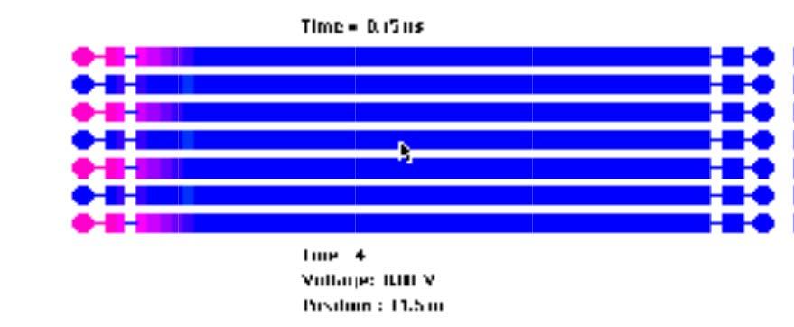
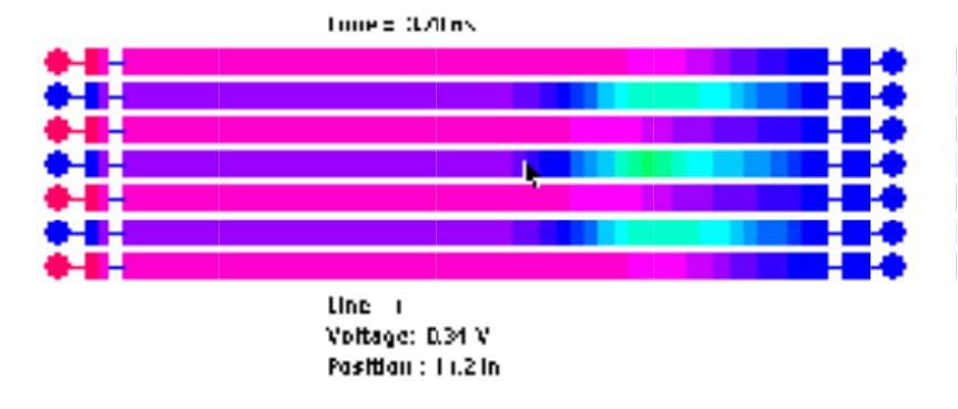
31 Multiconductor Simulation 31
32 LOSSY COUPLED TRANSMISSION LINES V 1 (z) V 2 (z) z=0 z=l... V 3 (z) L, C V = RI + L z I = GV + C z Solution is best found using a numerical approach (See References) I t V t 32
33 Three Line Microstrip V1 I1 I2 I = L11 + L12 + L13 z t t t 3 I1 V1 V2 V = C11 + C12 + C13 z t t t 3 V2 I1 I2 I = L21 + L22 + L23 z t t t 3 I2 V1 V2 V = C21 + C22 + C23 z t t t 3 V I I I = L + L + L z t t t I V V V = C + C + C z t t t
34 Three Line Alpha Mode Subtract (1c) from (1a) and (2c) from (2a), we get Vα I = ( L11 L13) z t Iα V = ( C11 C13) z t This defines the Alpha mode with: α α and I Vα = V1 V = I α 1 I3 3 The wave impedance of that mode is: Z α = L C L C and the velocity is u α = 1 ( L L )( C C )
35 Three Line Modal Decomposition In order to determine the next mode, assume that V = V + βv + V β I = I + β I + I β Vβ I I I = z t t t ( L βl L ) ( L βl L ) ( L βl L ) I β V V V = z t t t ( C βc C ) ( C βc C ) ( C βc C ) By reciprocity L 32 = L 23, L 21 = L 12, L 13 = L 31 By symmetry, L 12 = L 23 Also by approximation, L 22 L 11, L 11 +L 13 L 11 35
36 Three Line Modal Decomposition Vβ I I3 I = ( L + βl + L ) + + ( 2L + βl ) z t t t In order to balance the right-hand side into I β, we need to have ( + β ) = β ( + β + ) β ( + β ) 2L L I L L L I L L I L = β L or β =± 2 Therefore the other two modes are defined as The Beta mode with 36
37 The Beta mode with Three Line Beta Mode Vβ = V + 2V + V Iβ = I + 2I + I The characteristic impedance of the Beta mode is: Z β = L + 2L + L C + 2C + C and propagation velocity of the Beta mode is 1 u = β ( L11 2L12 L13 )( C11 2C12 C13 ) 37
38 Three Line Delta Mode The Delta mode is defined such that V = V δ 2V + V I = I δ 2I + I The characteristic impedance of the Delta mode is Z δ = L 2L + L C 2C + C The propagation velocity of the Delta mode is: 1 u = δ + + ( L11 2L12 L13 )( C11 2C12 C13 ) 38
39 Symmetric 3 Line Microstrip In summary: we have 3 modes for the 3-line system E = Alpha mode Beta mode* Delta mode* *neglecting coupling between nonadjacent lines 39
40 Coplanar Waveguide ε r = LnH ( / m) = C( pf/ m) = E = H =
41 Coplanar Waveguide ε r = 4.3 Z m ( Ω ) = Z c ( Ω ) = vp ( m/ ns) =
42 Coplanar Waveguide S' W S W S' h ε r Kk ( ) : Complete Elliptic Integral of the first kind S k = 30 π K'( k) S + 2W Zocp = (ohm) ε ( ) r + 1 Kk K'( k) = K( k') 2 k' = (1 k ) 2 1/2 v cp 2 = εr + 1 1/2 c 42
43 Coplanar Strips W S W h ε r Z ocs = 120 π K'( k) (ohm) ε 1 Kk ( ) r
44 Qualitative Comparison Characteristic Microstrip Coplanar Wguide Coplanar strips ε eff * ~6.5 ~5 ~5 Power handling High Medium Medium Radiation loss Low Medium Medium Unloaded Q High Medium Low or High Dispersion Small Medium Medium Mounting (shunt) Hard Easy Easy Mounting (series) Easy Easy Easy * Assuming ε r =10 and h=0.025 inch 44
45 3-Line Matching Network Extend matching network synthesis to multiconductor transmission line (MTL) systems, specifically coupled microstrip Characterize MTL systems by their normal mode parameters Mode configurations Propagation constants Characteristic impedance matrices 45


46 Longitudinal Immittance Matrix Functions (LIMFs) Given terminations, the immittance matrices are expressed as input longitudinal functions looking toward the load S Y m,c m,c in,out, Γ,, Z m,c in,out m,c in,out 46


47 Calibration Methods 1st order calibration: 6 distinct TRL calibrations were required to deembed the fan-in and fan-out sections 2nd order calibration: 1 multimode TRL calibration required to deembed all fan-ins and fan-outs Multiconductor transmission line matching network device under test 47

48 Bias Networks and Multiline/Multimode TRL Self-biasing for DC power done using air bridges Regulator circuit may be built on board with surface mount/chip components Calibration must include all modes and allow for the 6- port discontinuity S- parameter measurement Proposed calibration fixture for transistor amplifier device discontinuity with self-biasing network 48


49 3-line Transistor Amplifier The general amplifier structure with generic matching networks Note that a transistor seating hole may be present for convenience, but is not necessary Photograph of a three-line transistor amplifier autobiased w/o matching networks 49
50 Transistor Amplifier Matching Matching pf chip cap pf chip cap. Gains GHz m=5.14 / um= GHz m=6.54 / um= 0.32 S-parameter comparison between unmatched and matched three-line amplifier. Dotted line - unmatched; dashed line - matched. Design frequency: 3.1 GHz. 50
51 V Transmission Line w signal strip h dielectric α ground 2p 51
52 V Line Characteristic Impedance 250 CHARACTERISTIC IMPEDANCE Zo (ohms) º 37.5º 45º 52.5º 60º Microstrip w/h Calculated values of the characteristic impedance for a single-line v-strip structure as a function of width-to-height ratio w/h. The relative dielectric constant is εr =
53 V Line Effective Permittivity º 37.5º EFFECTIVE PERMITTIVITY º 52.5º Effective Relative Dielectric Constant º Microstrip w/h Calculated values of the effective relative dielectric constant for a single-line v-strip structure as a function of width-to-height ratio w/h. The relative dielectric constant is εr =
54 Three Line V Transmission Line y signal strip w s 2p h ground surface dielectric x Region 1 Region 2 Region 3 Region 4 Region 5 Region 6 54
55 V Line and Microstrip Microstrip C (pf/m) = L (nh/m) = V-line C (pf/m) = L (nh/m) = y w s signal strip 2p h ground surface dielectric x Region 1 Region 2 Region 3 Region 4 Region 5 Region 6 Comparison of the inductance and capacitance matrices between a three-line v-line and microstrip structures. The parameters are p/h = 0.8 mils, w/h = 0.6 and ε r =
56 V Line: Coupling Coefficients 350 Mutual Inductance 40 Mutual Capacitance L m (nh/m) V-line microstrip C m (pf/m) V-line microstrip s/h s/h Plot of mutual inductance (top) and mutual capacitance (bottom) versus spacing-to-height ratio for v-line and microstrip configurations. The parameters are w/h = 0.24, εr =
57 V Line vs Microstrip: Coupling Coefficients Coupling Coefficient V-line microstrip K v s/h Plot of the coupling coefficient versus spacing-to-height ratio for v-line and microstrip configurations. The parameters are w/h = 0.24, εr =
58 Advantages of V Line ground reference signal strip w signal strip dielectric substrate h dielectric α ground ground reference 2p Propagation Function Advantages of V Line * Higher bandwidth microstrip V-60 V-30 * Lower crosstalk * Better transition Linear Attenuation Frequency (GHz) 58
59 Advantages of V Line ground reference signal strip w signal strip dielectric substrate h dielectric α ground ground reference 2p Propagation Function Advantages of V Line * Higher bandwidth microstrip V-60 V-30 * Lower crosstalk * Better transition Linear Attenuation Frequency (GHz) 59
60 V Line vs Microstrip: Insertion Loss 0 Insertion Loss 20*log10* S Vline Microstrip Frequency (GHz) 60
61 References J. E. Schutt-Aine and R. Mittra, "Transient analysis of coupled lossy transmission lines with nonlinear terminations," IEEE Trans. Circuit Syst., vol. CAS-36, pp , July J. E. Schutt-Aine and D. B. Kuznetsov, "Efficient transient simulation of distributed interconnects," Int. Journ. Computation Math. Electr. Eng. (COMPEL), vol. 13, no. 4, pp , Dec D. B. Kuznetsov and J. E. Schutt-Ainé, "The optimal transient simulation of transmission lines," IEEE Trans. Circuits Syst.-I., vol. cas-43, pp , February W. T. Beyene and J. E. Schutt-Ainé, "Efficient Transient Simulation of High-Speed Interconnects Characterized by Sampled Data," IEEE Trans. Comp., Hybrids, Manufacturing Tech. vol. 21, pp , February
ECE 497 JS Lecture -07 Planar Transmission Lines
 ECE 497 JS Lecture -07 Planar Transmission Lines Spring 2004 Jose E. Schutt-Aine Electrical & Computer Engineering University of Illinois jose@emlab.uiuc.edu 1 Microstrip ε Z o w/h < 3.3 2 119.9 h h =
ECE 546 Lecture 07 Multiconductors
 ECE 546 Lecture 07 Multiconductors Spring 2018 Jose E. Schutt-Aine Electrical & Computer Engineering University of Illinois jesa@illinois.edu ECE 546 Jose Schutt Aine 1 TELGRAPHER S EQUATION FOR N COUPLED
ECE 451 Transmission Lines & Packaging
 Transmission Lines & Packaging Jose E. Schutt-Aine Electrical & Computer Engineering University of Illinois jose@emlab.uiuc.edu 1 Radio Spectrum Bands The use of letters to designate bands has long ago
ECE 497 JS Lecture - 13 Projects
 ECE 497 JS Lecture - 13 Projects Spring 2004 Jose E. Schutt-Aine Electrical & Computer Engineering University of Illinois jose@emlab.uiuc.edu 1 ECE 497 JS - Projects All projects should be accompanied
ECE 546 Lecture 13 Scattering Parameters
 ECE 546 Lecture 3 Scattering Parameters Spring 08 Jose E. Schutt-Aine Electrical & Computer Engineering University of Illinois jesa@illinois.edu ECE 546 Jose Schutt Aine Transfer Function Representation
ECE 451 Advanced Microwave Measurements. TL Characterization
 ECE 451 Advanced Microwave Measurements TL Characterization Jose E. Schutt-Aine Electrical & Computer Engineering University of Illinois jesa@illinois.edu ECE 451 Jose Schutt-Aine 1 Maxwell s Equations
ECE 497 JS Lecture -03 Transmission Lines
 ECE 497 JS Lecture -03 Transmission Lines Spring 2004 Jose E. Schutt-Aine Electrical & Computer Engineering University of Illinois jose@emlab.uiuc.edu 1 MAXWELL S EQUATIONS B E = t Faraday s Law of Induction
TC 412 Microwave Communications. Lecture 6 Transmission lines problems and microstrip lines
 TC 412 Microwave Communications Lecture 6 Transmission lines problems and microstrip lines RS 1 Review Input impedance for finite length line Quarter wavelength line Half wavelength line Smith chart A
Accounting for High Frequency Transmission Line Loss Effects in HFSS. Andrew Byers Tektronix
 Accounting for High Frequency Transmission Line Loss Effects in HFSS Andrew Byers Tektronix Transmission Line Refresher γ = α + j β = (R + jωl) * (G + jωc) Zo = Zr + j Zi = (R + jωl) / (G + jωc) Transmission
ECE 497 JS Lecture - 18 Noise in Digital Circuits
 ECE 497 JS Lecture - 18 Noise in Digital Circuits Spring 2004 Jose E. Schutt-Aine Electrical & Computer Engineering University of Illinois jose@emlab.uiuc.edu 1 Announcements Thursday April 15 th Speaker:
Non-Sinusoidal Waves on (Mostly Lossless)Transmission Lines
Transmission Lines") Non-Sinusoidal Waves on (Mostly Lossless)Transmission Lines Don Estreich Salazar 21C Adjunct Professor Engineering Science October 212 https://www.iol.unh.edu/services/testing/sas/tools.php 1 Outline of
Non-Sinusoidal Waves on (Mostly Lossless)Transmission Lines Don Estreich Salazar 21C Adjunct Professor Engineering Science October 212 https://www.iol.unh.edu/services/testing/sas/tools.php 1 Outline of
ECE414/514 Electronics Packaging Spring 2012 Lecture 6 Electrical D: Transmission lines (Crosstalk) Lecture topics
 Lecture topics") ECE414/514 Electronics Packaging Spring 2012 Lecture 6 Electrical D: Transmission lines (Crosstalk) James E. Morris Dept of Electrical & Computer Engineering Portland State University 1 Lecture topics
ECE414/514 Electronics Packaging Spring 2012 Lecture 6 Electrical D: Transmission lines (Crosstalk) James E. Morris Dept of Electrical & Computer Engineering Portland State University 1 Lecture topics
Lecture 12. Microwave Networks and Scattering Parameters
 Lecture Microwave Networs and cattering Parameters Optional Reading: teer ection 6.3 to 6.6 Pozar ection 4.3 ElecEng4FJ4 LECTURE : MICROWAE NETWORK AND -PARAMETER Microwave Networs: oltages and Currents
Effects from the Thin Metallic Substrate Sandwiched in Planar Multilayer Microstrip Lines
 Progress In Electromagnetics Research Symposium 2006, Cambridge, USA, March 26-29 115 Effects from the Thin Metallic Substrate Sandwiched in Planar Multilayer Microstrip Lines L. Zhang and J. M. Song Iowa
Transmission Line Basics II - Class 6
 Transmission Line Basics II - Class 6 Prerequisite Reading assignment: CH2 Acknowledgements: Intel Bus Boot Camp: Michael Leddige Agenda 2 The Transmission Line Concept Transmission line equivalent circuits
Analysis of Characteristics of Coplanar Waveguide with Finite Ground-planes by the Method of Lines
 PIERS ONLINE, VOL. 6, NO. 1, 21 46 Analysis of Characteristics of Coplanar Waveguide with Finite Ground-planes by the Method of Lines Min Wang, Bo Gao, Yu Tian, and Ling Tong College of Automation Engineering,
Topic 5: Transmission Lines
 Topic 5: Transmission Lines Profs. Javier Ramos & Eduardo Morgado Academic year.13-.14 Concepts in this Chapter Mathematical Propagation Model for a guided transmission line Primary Parameters Secondary
Microwave Network Analysis
 Prof. Dr. Mohammad Tariqul Islam titareq@gmail.my tariqul@ukm.edu.my Microwave Network Analysis 1 Text Book D.M. Pozar, Microwave engineering, 3 rd edition, 2005 by John-Wiley & Sons. Fawwaz T. ILABY,
Microwave Phase Shift Using Ferrite Filled Waveguide Below Cutoff
 Microwave Phase Shift Using Ferrite Filled Waveguide Below Cutoff CHARLES R. BOYD, JR. Microwave Applications Group, Santa Maria, California, U. S. A. ABSTRACT Unlike conventional waveguides, lossless
Electromagnetic Modeling and Signal Integrity Simulation of Power/Ground Networks in High Speed Digital Packages and Printed Circuit Boards
 Electromagnetic Modeling and Signal Integrity Simulation of Power/Ground Networks in High Speed Digital Packages and Printed Circuit Boards Frank Y. Yuan Viewlogic Systems Group, Inc. 385 Del Norte Road
Experiment 06 - Extraction of Transmission Line Parameters
 ECE 451 Automated Microwave Measurements Laboratory Experiment 06 - Extraction of Transmission Line Parameters 1 Introduction With the increase in both speed and complexity of mordern circuits, modeling
Networks and Systems Prof. V. G. K. Murti Department of Electrical Engineering Indian Institution of Technology, Madras
 Networks and Systems Prof. V. G. K. Murti Department of Electrical Engineering Indian Institution of Technology, Madras Lecture - 32 Network Function (3) 2-port networks: Symmetry Equivalent networks Examples
TASK A. TRANSMISSION LINE AND DISCONTINUITIES
 TASK A. TRANSMISSION LINE AND DISCONTINUITIES Task A. Transmission Line and Discontinuities... 1 A.I. TEM Transmission Line... A.I.1. Circuit Representation of a Uniform Transmission Line... A.I.. Time
Transmission-Reflection Method to Estimate Permittivity of Polymer
 Transmission-Reflection Method to Estimate Permittivity of Polymer Chanchal Yadav Department of Physics & Electronics, Rajdhani College, University of Delhi, Delhi, India Abstract In transmission-reflection
Electromagnetic Parameters Extraction for Integrated-circuit Interconnects for Open Three conductors with Two Levels Systems
 Electromagnetic Parameters Extraction for Integrated-circuit Interconnects for Open Three conductors with Two Levels Systems S. M. Musa, M. N. O. Sadiku, and J. D. Oliver Corresponding author: S.M. Musa
Analyzing of Coupling Region for CRLH/RH TL Coupler with Lumped-elements
 PIERS ONLINE, VOL. 3, NO. 5, 27 564 Analyzing of Coupling Region for CRLH/RH TL Coupler with Lumped-elements Y. Wang 2, Y. Zhang, 2, and F. Liu 2 Pohl Institute of Solid State Physics, Tongji University,
and Ee = E ; 0 they are separated by a dielectric material having u = io-s S/m, µ, = µ, 0
 602 CHAPTER 11 TRANSMISSION LINES 11.10 Two identical pulses each of magnitude 12 V and width 2 µs are incident at t = 0 on a lossless transmission line of length 400 m terminated with a load. If the two
ESE 570: Digital Integrated Circuits and VLSI Fundamentals
 ESE 570: Digital Integrated Circuits and VLSI Fundamentals Lec 24: April 19, 2018 Crosstalk and Wiring, Transmission Lines Lecture Outline! Crosstalk! Repeaters in Wiring! Transmission Lines " Where transmission
Name. Section. Short Answer Questions. 1. (20 Pts) 2. (10 Pts) 3. (5 Pts) 4. (10 Pts) 5. (10 Pts) Regular Questions. 6. (25 Pts) 7.
 2. (10 Pts) 3. (5 Pts) 4. (10 Pts) 5. (10 Pts) Regular Questions. 6. (25 Pts) 7.") Name Section Short Answer Questions 1. (20 Pts) 2. (10 Pts) 3. (5 Pts). (10 Pts) 5. (10 Pts) Regular Questions 6. (25 Pts) 7. (20 Pts) Notes: 1. Please read over all questions before you begin your work.
Name Section Short Answer Questions 1. (20 Pts) 2. (10 Pts) 3. (5 Pts). (10 Pts) 5. (10 Pts) Regular Questions 6. (25 Pts) 7. (20 Pts) Notes: 1. Please read over all questions before you begin your work.
! Crosstalk. ! Repeaters in Wiring. ! Transmission Lines. " Where transmission lines arise? " Lossless Transmission Line.
 ESE 570: Digital Integrated Circuits and VLSI Fundamentals Lec 24: April 19, 2018 Crosstalk and Wiring, Transmission Lines Lecture Outline! Crosstalk! Repeaters in Wiring! Transmission Lines " Where transmission
ECE 546 Lecture 11 MOS Amplifiers
 ECE 546 Lecture MOS Amplifiers Spring 208 Jose E. Schutt-Aine Electrical & Computer Engineering University of Illinois jesa@illinois.edu ECE 546 Jose Schutt Aine Amplifiers Definitions Used to increase
Modeling frequency-dependent conductor losses and dispersion in serial data channel interconnects
 Modeling frequency-dependent conductor losses and dispersion in serial data channel interconnects Yuriy Shlepnev Simberian Inc., www.simberian.com Abstract: Models of transmission lines and transitions
A Novel Tunable Dual-Band Bandstop Filter (DBBSF) Using BST Capacitors and Tuning Diode
 Using BST Capacitors and Tuning Diode") Progress In Electromagnetics Research C, Vol. 67, 59 69, 2016 A Novel Tunable Dual-Band Bandstop Filter (DBBSF) Using BST Capacitors and Tuning Diode Hassan Aldeeb and Thottam S. Kalkur * Abstract A novel
Progress In Electromagnetics Research C, Vol. 67, 59 69, 2016 A Novel Tunable Dual-Band Bandstop Filter (DBBSF) Using BST Capacitors and Tuning Diode Hassan Aldeeb and Thottam S. Kalkur * Abstract A novel
Transmission Lines. Author: Michael Leddige
 Transmission Lines Author: Michael Leddige 1 Contents PCB Transmission line structures Equivalent Circuits and Key Parameters Lossless Transmission Line Analysis Driving Reflections Systems Reactive Elements
IBIS Modeling Using Latency Insertion Method (LIM)
") IBIS Modeling Using Latency Insertion Method (LIM) José E. Schutt Ainé University of Illinois at Urbana- Champaign Jilin Tan, Ping Liu, Feras Al Hawari, Ambrish arma Cadence Design Systems European IBIS
IBIS Modeling Using Latency Insertion Method (LIM) José E. Schutt Ainé University of Illinois at Urbana- Champaign Jilin Tan, Ping Liu, Feras Al Hawari, Ambrish arma Cadence Design Systems European IBIS
ECE 546 Lecture 10 MOS Transistors
 ECE 546 Lecture 10 MOS Transistors Spring 2018 Jose E. Schutt-Aine Electrical & Computer Engineering University of Illinois jesa@illinois.edu NMOS Transistor NMOS Transistor N-Channel MOSFET Built on p-type
GHz 6-Bit Digital Phase Shifter
 180 90 45 22.5 11.25 5.625 ASL 2004P7 3.1 3.5 GHz 6-Bit Digital Phase Shifter Features Functional Diagram Frequency Range: 3.1 to 3.5 GHz RMS Error < 2 deg. 5 db Insertion Loss TTL Control Inputs 0.5-um
INTRODUCTION TO TRANSMISSION LINES DR. FARID FARAHMAND FALL 2012
 INTRODUCTION TO TRANSMISSION LINES DR. FARID FARAHMAND FALL 2012 http://www.empowermentresources.com/stop_cointelpro/electromagnetic_warfare.htm RF Design In RF circuits RF energy has to be transported
ECE 546 Lecture 04 Resistance, Capacitance, Inductance
 ECE 546 Lecture 04 Resistance, Capacitance, Inductance Spring 2018 Jose E. Schutt-Aine Electrical & Computer Engineering University of Illinois jschutt@emlab.uiuc.edu ECE 546 Jose Schutt Aine 1 What is
ECE 497 JS Lecture - 18 Impact of Scaling
 ECE 497 JS Lecture - 18 Impact of Scaling Spring 2004 Jose E. Schutt-Aine Electrical & Computer Engineering University of Illinois jose@emlab.uiuc.edu 1 Announcements Thursday April 8 th Speaker: Prof.
Network Theory and the Array Overlap Integral Formulation
 Chapter 7 Network Theory and the Array Overlap Integral Formulation Classical array antenna theory focuses on the problem of pattern synthesis. There is a vast body of work in the literature on methods
NONLINEAR TRAVELING-WAVE FIELD-EFFECT TRAN- SISTORS FOR MANAGING DISPERSION-FREE ENVE- LOPE PULSES
 Progress In Electromagnetics Research Letters, Vol. 23, 29 38, 2011 NONLINEAR TRAVELING-WAVE FIELD-EFFECT TRAN- SISTORS FOR MANAGING DISPERSION-FREE ENVE- LOPE PULSES K. Narahara Graduate School of Science
STUB BASED EQUIVALENT CIRCUIT MODELS FOR EVEN/ODD MODE DUAL CRLH UNIT CELLS. Faculty of Engineering, Ain Shams University, Cairo, Egypt
 Progress In Electromagnetics Research M, Vol. 3, 95 9, 3 STUB BASED EQUIVALENT CIRCUIT MODELS FOR EVEN/ODD MODE DUAL CRLH UNIT CELLS Amr M. E. Safwat, *, Amr A. Ibrahim, Mohamed A. Othman, Marwah Shafee,
ECE 6340 Fall Homework 2. Please do the following problems (you may do the others for practice if you wish): Probs. 1, 2, 3, 4, 5, 6, 7, 10, 12
: Probs. 1, 2, 3, 4, 5, 6, 7, 10, 12") ECE 634 Fall 16 Homework Please do the following problems (you may do the others for practice if you wish: Probs. 1,, 3, 4, 5, 6, 7, 1, 1 1 Consider two parallel infinite wires in free space each carrying
ECE 634 Fall 16 Homework Please do the following problems (you may do the others for practice if you wish: Probs. 1,, 3, 4, 5, 6, 7, 1, 1 1 Consider two parallel infinite wires in free space each carrying
Equivalent Circuit Model Extraction for Interconnects in 3D ICs
 Equivalent Circuit Model Extraction for Interconnects in 3D ICs A. Ege Engin Assistant Professor, Department of ECE, San Diego State University Email: aengin@mail.sdsu.edu ASP-DAC, Jan. 23, 213 Outline
EE 205 Dr. A. Zidouri. Electric Circuits II. Two-Port Circuits Two-Port Parameters. Lecture #42
 EE 05 Dr. A. Zidouri Electric Circuits Two-Port Circuits Two-Port Parameters Lecture #4-1 - EE 05 Dr. A. Zidouri The material to be covered in this lecture is as follows: o ntroduction to two-port circuits
ECE 451 Macromodeling
 ECE 451 Macromodeling Jose E. Schutt-Aine Electrical & Computer Engineering University of Illinois jesa@illinois.edu ECE 451 Jose Schutt Aine 1 Blackbox Macromodeling Nonlinear Network 1 Nonlinear Network
Statistical approach in complex circuits by a wavelet based Thevenin s theorem
 Proceedings of the 11th WSEAS International Conference on CIRCUITS, Agios Nikolaos, Crete Island, Greece, July 23-25, 2007 185 Statistical approach in complex circuits by a wavelet based Thevenin s theorem
ALGORITHM FOR ACCURATE CAPACITANCE MATRIX MEASUREMENTS OF THE MULTICONDUCTOR STRUCTURE FOR VLSI INTERCONNECTIONS
 ALGORITHM FOR ACCURATE CAPACITANCE MATRIX MEASUREMENTS OF THE MULTICONDUCTOR STRUCTURE FOR VLSI INTERCONNECTIONS Lech ZNAMIROWSKI Olgierd A. PALUSINSKI DEPARTMENT OF AUTOMATIC CONTROL, DEPARTMENT OF ELECTRICAL
EELE 3332 Electromagnetic II Chapter 11. Transmission Lines. Islamic University of Gaza Electrical Engineering Department Dr.
 EEE 333 Electromagnetic II Chapter 11 Transmission ines Islamic University of Gaza Electrical Engineering Department Dr. Talal Skaik 1 1 11.1 Introduction Wave propagation in unbounded media is used in
Conventional Paper-I Part A. 1. (a) Define intrinsic wave impedance for a medium and derive the equation for intrinsic vy
 Define intrinsic wave impedance for a medium and derive the equation for intrinsic vy") EE-Conventional Paper-I IES-01 www.gateforum.com Conventional Paper-I-01 Part A 1. (a) Define intrinsic wave impedance for a medium and derive the equation for intrinsic vy impedance for a lossy dielectric
EE-Conventional Paper-I IES-01 www.gateforum.com Conventional Paper-I-01 Part A 1. (a) Define intrinsic wave impedance for a medium and derive the equation for intrinsic vy impedance for a lossy dielectric
Finite Element Method Analysis of Symmetrical Coupled Microstrip Lines
 International Journal of Computing and Digital Systems ISSN (20-142X) Int. J. Com. Dig. Sys. 3, No.3 (Sep-2014) Finite Element Method Analysis of Symmetrical Coupled Microstrip Lines Sarhan M. Musa and
Analytical Solution for Capacitance and Characteristic Impedance of CPW with Defected Structures in Signal line
 Progress In Electromagnetics Research Letters, Vol. 54, 79 84, 25 Analytical Solution for Capacitance and Characteristic Impedance of CPW with Defected Structures in Signal line Naibo Zhang, Zhongliang
Electric Circuit Theory
 Electric Circuit Theory Nam Ki Min nkmin@korea.ac.kr 010-9419-2320 Chapter 18 Two-Port Circuits Nam Ki Min nkmin@korea.ac.kr 010-9419-2320 Contents and Objectives 3 Chapter Contents 18.1 The Terminal Equations
INF5481 RF Circuit, Theory and Design Assignment #3
 INF548 RF Circuit, Theory and Design ssignment #3 Problem We have the two port network in figure, which is a cascade of two identical networks consisting of a single shunt and series impedance. Find the
Scattering Parameters
 Berkeley Scattering Parameters Prof. Ali M. Niknejad U.C. Berkeley Copyright c 2016 by Ali M. Niknejad September 7, 2017 1 / 57 Scattering Parameters 2 / 57 Scattering Matrix Voltages and currents are
Design of all-pole microwave filters. Giuseppe Macchiarella Polytechnic of Milan, Italy Electronic and Information Department
 Design of all-pole microwave filters Giuseppe Macchiarella Polytechnic of Milan, Italy Electronic and Information Department In-line filters with all-equal resonators R L eq, f L eq, f L eq, f L eq, f
Broadband transmission line models for analysis of serial data channel interconnects
 PCB Design Conference East, Durham NC, October 23, 2007 Broadband transmission line models for analysis of serial data channel interconnects Y. O. Shlepnev, Simberian, Inc. shlepnev@simberian.com Simberian:
Kimmo Silvonen, Transmission lines, ver
 Kimmo Silvonen, Transmission lines, ver. 13.10.2008 1 1 Basic Theory The increasing operating and clock frequencies require transmission line theory to be considered more and more often! 1.1 Some practical
JUST THE MATHS UNIT NUMBER 9.9. MATRICES 9 (Modal & spectral matrices) A.J.Hobson
 A.J.Hobson") JUST THE MATHS UNIT NUMBER 9.9 MATRICES 9 (Modal & spectral matrices) by A.J.Hobson 9.9. Assumptions and definitions 9.9.2 Diagonalisation of a matrix 9.9.3 Exercises 9.9.4 Answers to exercises UNIT 9.9
JUST THE MATHS UNIT NUMBER 9.9 MATRICES 9 (Modal & spectral matrices) by A.J.Hobson 9.9. Assumptions and definitions 9.9.2 Diagonalisation of a matrix 9.9.3 Exercises 9.9.4 Answers to exercises UNIT 9.9
Lecture 2 - Transmission Line Theory
 Lecture 2 - Transmission Line Theory Microwave Active Circuit Analysis and Design Clive Poole and Izzat Darwazeh Academic Press Inc. Poole-Darwazeh 2015 Lecture 2 - Transmission Line Theory Slide1 of 54
Application of EM- Simulators for Extraction of Line Parameters
 Chapter - 2 Application of EM- Simulators for Extraction of Line Parameters 2. 1 Introduction The EM-simulators-2D, 2.5D and 3D, are powerful tools for the analysis of the planar transmission lines structure.
Lecture 17 Date:
 Lecture 17 Date: 09.03.017 The Quadrature Hybrid We began our discussion of dividers and couplers by considering important general properties of three- and four-port networks. This was followed by an analysis
EMC Considerations for DC Power Design
 EMC Considerations for DC Power Design Tzong-Lin Wu, Ph.D. Department of Electrical Engineering National Sun Yat-sen University Power Bus Noise below 5MHz 1 Power Bus Noise below 5MHz (Solution) Add Bulk
Boundary and Excitation Training February 2003
 Boundary and Excitation Training February 2003 1 Why are They Critical? For most practical problems, the solution to Maxwell s equations requires a rigorous matrix approach such as the Finite Element Method
CHAPTER.4: Transistor at low frequencies
 CHAPTER.4: Transistor at low frequencies Introduction Amplification in the AC domain BJT transistor modeling The re Transistor Model The Hybrid equivalent Model Introduction There are three models commonly
DESIGN AND OPTIMIZATION OF EQUAL SPLIT BROADBAND MICROSTRIP WILKINSON POWER DI- VIDER USING ENHANCED PARTICLE SWARM OPTI- MIZATION ALGORITHM
 Progress In Electromagnetics Research, Vol. 118, 321 334, 2011 DESIGN AND OPTIMIZATION OF EQUAL SPLIT BROADBAND MICROSTRIP WILKINSON POWER DI- VIDER USING ENHANCED PARTICLE SWARM OPTI- MIZATION ALGORITHM
Solutions to Problems in Chapter 6
 Appendix F Solutions to Problems in Chapter 6 F.1 Problem 6.1 Short-circuited transmission lines Section 6.2.1 (book page 193) describes the method to determine the overall length of the transmission line
Lecture 23. Dealing with Interconnect. Impact of Interconnect Parasitics
 Lecture 23 Dealing with Interconnect Impact of Interconnect Parasitics Reduce Reliability Affect Performance Classes of Parasitics Capacitive Resistive Inductive 1 INTERCONNECT Dealing with Capacitance
Advancements in mm-wave On-Wafer Measurements: A Commercial Multi-Line TRL Calibration Author: Leonard Hayden Presenter: Gavin Fisher
 Advancements in mm-wave On-Wafer Measurements: A Commercial Multi-Line TRL Calibration Author: Leonard Hayden Presenter: Gavin Fisher The title of this section is A Commercial Multi-Line TRL Calibration
SCSI Connector and Cable Modeling from TDR Measurements
 SCSI Connector and Cable Modeling from TDR Measurements Dima Smolyansky TDA Systems, Inc. http://www.tdasystems.com Presented at SCSI Signal Modeling Study Group Rochester, MN, December 1, 1999 Outline
Electrical Package Design TKK 2009 Lecture 2
 Electrical Package Design TKK 2009 Lecture 2 James E. Morris Dept of Electrical & Computer Engineering Portland State University i Electrical Package Design Lecture topics A: Introduction CMOS; R, L, &
Conventional Paper I-2010
 Conventional Paper I-010 1. (a) Sketch the covalent bonding of Si atoms in a intrinsic Si crystal Illustrate with sketches the formation of bonding in presence of donor and acceptor atoms. Sketch the energy
ANTENNAS and MICROWAVES ENGINEERING (650427)
") Philadelphia University Faculty of Engineering Communication and Electronics Engineering ANTENNAS and MICROWAVES ENGINEERING (65427) Part 2 Dr. Omar R Daoud 1 General Considerations It is a two-port network
Philadelphia University Faculty of Engineering Communication and Electronics Engineering ANTENNAS and MICROWAVES ENGINEERING (65427) Part 2 Dr. Omar R Daoud 1 General Considerations It is a two-port network
Progress In Electromagnetics Research M, Vol. 20, 73 80, 2011
 Progress In Electromagnetics Research M, Vol. 20, 73 80, 2011 COPLANAR METAMATERIAL MICRO-RESONATOR S. Nemer 1, 2, *, B. Sauviac 1, B. Bayard 1, J. J. Rousseau 1, C. Nader 2, J. Bechara 2, and A. Khoury
PHY3128 / PHYM203 (Electronics / Instrumentation) Transmission Lines
 Transmission Lines") Transmission Lines Introduction A transmission line guides energy from one place to another. Optical fibres, waveguides, telephone lines and power cables are all electromagnetic transmission lines. are
Transmission Lines Introduction A transmission line guides energy from one place to another. Optical fibres, waveguides, telephone lines and power cables are all electromagnetic transmission lines. are
Differential Impedance finally made simple
 Slide - Differential Impedance finally made simple Eric Bogatin President Bogatin Enterprises 93-393-305 eric@bogent.com Slide -2 Overview What s impedance Differential Impedance: a simple perspective
ECE 342 Electronic Circuits. Lecture 6 MOS Transistors
 ECE 342 Electronic Circuits Lecture 6 MOS Transistors Jose E. Schutt-Aine Electrical & Computer Engineering University of Illinois jesa@illinois.edu 1 NMOS Transistor Typically L = 0.1 to 3 m, W = 0.2
Lecture 19 Date:
 Lecture 19 Date: 8.10.014 The Quadrature Hybrid We began our discussion of dividers and couplers by considering important general properties of three- and fourport networks. This was followed by an analysis
Comparison of MLCC and X2Y Technology for Use in Decoupling Circuits
 Comparison of MLCC and X2Y Technology for Use in Decoupling Circuits Dale L. Sanders James P. Muccioli Anthony A. Anthony X2Y Attenuators, LLC 37554 Hills Tech Dr. Farmington Hills, MI 48331 248-489-0007
ECE 546 Lecture 15 Circuit Synthesis
 ECE 546 Lecture 15 Circuit Synthesis Spring 018 Jose E. Schutt-Aine Electrical & Computer Engineering University of Illinois jesa@illinois.edu ECE 546 Jose Schutt Aine 1 MOR via Vector Fitting Rational
2GHz Microstrip Low Pass Filter Design with Open-Circuited Stub
 IOSR Journal of Electronics and Communication Engineering (IOSR-JECE) e-issn: 2278-2834,p- ISSN: 2278-8735.Volume 13, Issue 2, Ver. II (Mar. - Apr. 2018), PP 01-09 www.iosrjournals.org 2GHz Microstrip
EECS 151/251A Spring 2018 Digital Design and Integrated Circuits. Instructors: Nick Weaver & John Wawrzynek. Lecture 12 EE141
 EECS 151/251A Spring 2018 Digital Design and Integrated Circuits Instructors: Nick Weaver & John Wawrzynek Lecture 12 1 Wire Models All-inclusive model Capacitance-only 2 Capacitance Capacitance: The Parallel
SYNTHESIS OF MICROWAVE RESONATOR DIPLEX- ERS USING LINEAR FREQUENCY TRANSFORMATION AND OPTIMIZATION
 Progress In Electromagnetics Research, Vol. 24, 44 4, 22 SYNTHESIS OF MICROWAVE RESONATOR DIPLEX- ERS USING LINEAR FREQUENCY TRANSFORMATION AND OPTIMIZATION R. Wang *, J. Xu, M.-Y. Wang, and Y.-L. Dong
MICROSTRIP NONUNIFORM IMPEDANCE RESONATORS
 Progress In Electromagnetics Research, PIER 67, 329 339, 2007 MICROSTRIP NONUNIFORM IMPEDANCE RESONATORS M. Khalaj-Amirhosseini College of Electrical Engineering Iran University of Science and Technology
STUDY OF LOSS EFFECT OF TRANSMISSION LINES AND VALIDITY OF A SPICE MODEL IN ELECTROMAG- NETIC TOPOLOGY
 Progress In Electromagnetics Research, PIER 90, 89 103, 2009 STUDY OF LOSS EFFECT OF TRANSMISSION LINES AND VALIDITY OF A SPICE MODEL IN ELECTROMAG- NETIC TOPOLOGY H. Xie, J. Wang, R. Fan, andy. Liu Department
SRAM System Design Guidelines
 Introduction This application note examines some of the important system design considerations an engineer should keep in mind when designing with Cypress SRAMs. It is important to note that while they
Design of Narrow Band Filters Part 2
 E.U.I.T. Telecomunicación 200, Madrid, Spain, 27.09 30.09.200 Design of Narrow Band Filters Part 2 Thomas Buch Institute of Communications Engineering University of Rostock Th. Buch, Institute of Communications
A GENERALIZED COUPLED-LINE DUAL-BAND WILKINSON POWER DIVIDER WITH EXTENDED PORTS
 Progress In Electromagnetics Research, Vol. 19, 197 14, 1 A GENERALIZED COUPLED-LINE DUAL-BAND WILKINSON POWER DIVIDER WITH EXTENDED PORTS J. C. Li *, Y. L. Wu, Y. A. Liu, J. Y. Shen, S. L. Li, and C.
EVALUATION OF COMPLEX PERMITTIVITIES OF MULTILAYER DIELECTRIC SUBSTRATES AT MICROWAVE FREQUENCIES USING WAVEGUIDE MEASUREMENTS
 EVALUATION OF COMPLEX PERMITTIVITIES OF MULTILAYER DIELECTRIC SUBSTRATES AT MICROWAVE FREQUENCIES USING WAVEGUIDE MEASUREMENTS R. L. Crave, M. D. Deshpande, C. J. Redd 3, and P. I. Tiemsin () NASA Langle
Broadband material model identification with GMS-parameters
 Broadband material model identification with GMS-parameters Yuriy Olegovich Shlepnev Simberian Inc. shlepnev@simberian.com 2015 EPEPS Conference, October 27, 2015 2015 Simberian Inc. Outline Introduction
AN B. Basic PCB traces transmission line effects causing signal integrity degradation simulation using Altium DXP version 6.
 AN200805-01B Basic PCB traces transmission line effects causing signal integrity degradation simulation using Altium DXP version 6.9 By Denis Lachapelle eng. and Anne Marie Coutu. May 2008 The objective
Modeling of Signal and Power Integrity in System on Package Applications
 Modeling of Signal and Power Integrity in System on Package Applications Madhavan Swaminathan and A. Ege Engin Packaging Research Center, School of Electrical and Computer Engineering, Georgia Institute
/$ IEEE
 IEEE TRANSACTIONS ON CIRCUITS AND SYSTEMS II: EXPRESS BRIEFS, VOL. 55, NO. 9, SEPTEMBER 2008 937 Analytical Stability Condition of the Latency Insertion Method for Nonuniform GLC Circuits Subramanian N.
Lipparini* anazysis which compare favourabzy with experimentaz results. The same modez. described. It is shown that the discrepancies between computed
 ACCURATE ANALYSIS AND DESIGN OF MICROSTRIP INTERDIGITATED COUPLERS Vittorio Rizzoli*- Alessandro Lipparini* Abstract. The ezectricaz behaviour of interdigitated directionaz coupzers in an inhomogeneous
Efficient Simulation of Lossy and Dispersive Transmission Lines
 Efficient Simulation of Lossy and Dispersive Transmission Lines Tuyen V. guyen* IBM Microelectronics, Hopewell Junction, Y 2533 Abstract - This paper presents an efficient method, based on the transfer
EECS 117 Lecture 3: Transmission Line Junctions / Time Harmonic Excitation
 EECS 117 Lecture 3: Transmission Line Junctions / Time Harmonic Excitation Prof. Niknejad University of California, Berkeley University of California, Berkeley EECS 117 Lecture 3 p. 1/23 Transmission Line
ECE 342 Electronic Circuits. Lecture 35 CMOS Delay Model
 ECE 34 Electronic Circuits Lecture 35 CMOS Delay Model Jose E. Schutt-Aine Electrical & Computer Engineering University of Illinois jesa@illinois.edu ECE 34 Jose Schutt Aine 1 Digital Circuits V IH : Input
Periodic FDTD Characterization of Guiding and Radiation Properties of Negative Refractive Index Transmission Line Metamaterials
 Periodic FDTD Characterization of Guiding and Radiation Properties of Negative Refractive Index Transmission Line Metamaterials Costas D. Sarris The Edward S. Rogers Sr. Department of Electrical and Computer
Modeling of Multiconductor Microstrip Systems on Microwave Integrated Circuits
 Modeling of Multiconductor Microstrip Systems on Microwave Integrated Circuits S. M. Musa, M. N. O. Sadiku, and K. T. Harris Roy G. Perry College of Engineering, Prairie View A&M University Prairie View,