Microwave Network Analysis
|
|
|
- Jade Freeman
- 5 years ago
- Views:
Transcription
1 Prof. Dr. Mohammad Tariqul Islam Microwave Network Analysis 1

2 Text Book D.M. Pozar, Microwave engineering, 3 rd edition, 2005 by John-Wiley & Sons. Fawwaz T. ILABY, Fundamentals of Applied Electromagnetics, 5 th edition, 2007 by Prentice Hall M. N. Sadiku, Elements of Electromagnetics 2
3 Typical GSM Mobile Handset 3
4 Typical GSM Mobile Handset Cont... RF Front End consists of microwave circuits and components. High frequency or microwave circuit design techniques are used. Different from conventional low frequency circuit theories. Understanding of electromagnetism is crucial. 4

5 An Example of Microwave Circuits You have learnt about this in Microwave Devices This is the coverage of Microwave components & Circuits. This part will be covered in RF transistor circuit design 5


6 Another Example of RF Circuit (BPF) 6
7 Example network 7

8 Microwave Circuit Cont... Transmission Line 8


9 More Microwave/RF Components and Circuit Examples Integrated circuits: 9


10 Examples Cont... Discretes:


11 Examples Cont... Connectors, coaxial & waveguides:


12 Examples Cont... Printed circuit board (PCB) assembly or other ceramic substrate:


13 Examples Cont... More PCB or ceramic substrates: Oscillator Microstrip antenna 13


14 Examples Cont... System level microwave circuits:

15 Examples Cont... Digital circuit for interfacing to PC Microstrip filter Dual band amplifier module, 15


16 Examples Cont... Ivan board, www-personal.ksu.edu/~wkuhn/facil.html 16
17 INTRODUCTION A microwave network is formed when a number of microwave components and devices (e.g. oscillator, amplifier etc) is connected together by a TL or waveguide for microwave transmission. The point connecting the two or more devices is called the junction. For a low frequency network, a base is a pair of terminals. For a microwave network, a base is a reference plate which crosses the length of a TL or Waveguide.
18 At a low frequency, the network physical length is very small compared to the of the signal sent. Thus, the measurable variable is the voltage and current at any points in the circuit. The phase change from one point to another is negligible. More interested to the voltage and current at one set of base, the power flow through a more global device or quantity. Can be related in term as Z-parameter, Y- parameter, h-parameter, or ABCD parameter.
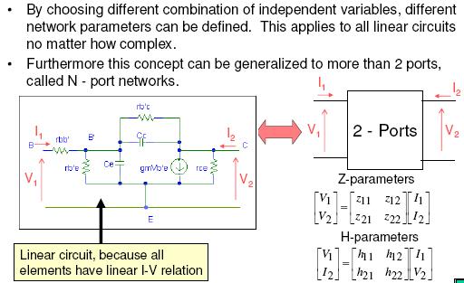
19 For a 2-base network, the relation is given by: Where Z ij, Y ij, h and A,B,C,D are suitable constants which characterises the junction D B h Y Z I V C A I V V I h h h I V V V Y Y Y I I I I Z Z Z V V
20 ABCD parameter is a suitable technique to represent each junction when the connected circuit is in a cascade order. Matrix product which explains the overall cascade relation is obtained by multiplying the matrices that explain each junctions. The parameters can be measured in an open or closed circuit for a circuit analysis. n n n n 1 1 D C B A D C B A D C B A D C B A
21 At a microwave frequency, the physical length of the component can be compared or longer than the wavelength. The voltage and current cannot be defined well at a given point on the microwave circuit. The measurement for Z, Y, h and ABCD parameters is difficult at this frequency because of the following reasons: There is no voltage and current terminal measuring device A closed and open circuit is difficult to obtain for a great frequency range. The presence of an active device causes the circuit to be instabilised for an open or closed circuit.
22 Thus, a microwave circuit is usually analysed using a scatter parameter or S-parameter. It relates the reflection wave amplitude and the incident wave linearly. The S-parameter can be related to Z, Y or ABCDparameters.

23 Example of Terminations 23
24 IMPEDANCE AND EQUIVALENT VOLTAGES AND CURRENTS Equivalent Voltages and Currents At microwave frequencies, the measurement of voltage or current is difficult (impossible!) unless a terminal pair is defined. Present in the case of TEM-type lines, but does not exist for non- TEM lines. Figure 1 shows the E and H line waves for a 2-base TEM TL. Voltage, V of the + conductor relative to the - conductor. V E. dl

25 The current flowing on the + conductor can be determined using Ampere s Law. I H. dl c Characteristic impedance Z o for traveling waves We may use the circuit theory for TL to characterise this line as a circuit element. For a non-tem, it is more difficult to obtain this parameter => use the equivalent concept.
26 Impedance Concept The term impedance was first used in the 19 th century to describe the complex ratio of V/I in ac circuits. Then, developed into TL. Then, applied into EM waves. Summary of impedance types: Medium intrinsic impedance Wave impedance Characteristic impedance Z w Z o E t 1 Y / H o t L C 1 Y w

27 IMPEDANCE & ADMITTANCE MATRICES Equivalent currents & voltages can be defined for TEM & non-tem waves. Once they have been defined at various points in the microwave network, the impedance & admittance matrix can be used to relate these port quantities. Consider N-port or arbitrary N-port microwave network (Figure 2). The port in Figure 2 can be any TL or one of the propagating modes in waveguides.
28 A base refers to a pair of 2-terminals. If one of the network base is a waveguide supporting more than one propagating modes, additional electric base is required for every mode. At a given point at the nth base, terminal plate, t n, is defined together with the equivalent voltage and current for the incident and reflection wave (V n+, I n + and V n-, I n- ). The terminal planes are important in providing a phase reference for voltage and current phasors.
29 Figure 2
30 At the nth terminal plate, the total voltage and current is given by: The impedance matrix [Z] for a microwave network relating this voltage and current is :
31 Or in matrix form as Admittance matrix [Y]: Or in matrix form as
32 [Z] and [Y] are inverse each other Matrix [Z] and [Y] relate the TOTAL voltages and currents. Z ij is can be found as: In words, Z ij can be obtained by driving port j with the current I j, open-circuiting all the ports (thus I k =0 for kj), and measuring the open circuit voltage at port I.
33 Thus, Z ii is the input impedance seen looking into port i when all other ports are open-circuited. Z ij is the transfer impedance between ports i and j when all other ports are open-circuited. Y ij can be found as: Y ij can be determined by driving port j with the voltage V j, short-circuiting all other ports (so V k =0 for kj) and measuring the short-circuit current at port i.
34 In general, each Z ij or Y ij, their elements may be complex. For an N-port network, the admittance and impedance matrices are N x N in size so there are 2N 2 independent quantities. Many networks are either reciprocal or lossless, or both. If the network is reciprocal (i.e. not containing any nonreciprocal element), Z and Y matrices are symmetric i.e. Z ij = Z ji and Y ij = Y ji. If the network is lossless, Z ij or Y ij elements are purely imaginary.
35 Reciprocal Networks Consider the arbitrary network (Figure 2) to be reciprocal with short circuit placed at all terminal planes except those of ports 1 and 2. Let E a, H a and E b, H b be the fields anywhere in the network due to two sources, a and b, located somewhere in the network. The reciprocity theorem states that s E H. ds E H. ds a b b a S is a closed surface along the boundaries of the network and through the terminal planes of the ports. s
36 If the boundary walls are metal, then E tan =0 on these walls. If they are open structures, the boundary can be taken far from the lines, so that E tan is negligible (nonzero). The nonzero quantity come from the cross-sectional areas of port 1 and 2. The fields due to sources a and b, evaluated from planes t 1 and t 2 are: E E E E 1a 1b 2a 2b V V V V 1 a 1b 2a 2b e e 1 1 e e 2 2 H H 1a H H 1b 2a 2b I 1a I I 1b I h 2a 2b 1 h 1 h h 2 2
37 e 1, h 1, e 2 and h 2 are the transverse modal fields of ports 1 and 2. V s and I s are the equivalent voltages and currents. S 1 and S 2 are the cross-sectional areas at the terminal planes of ports 1 and 2. Thus, V 1a I 1b V 1b I 1a + V 2a I 2b V 2b I 2a = 0 Use the 2x2 admittance matrix of the 2-ports networks to eliminate the I s. So: I 1 = Y 11 V 1 + Y 12 V 2 I 2 = Y 21 V 1 + Y 22 V 2
38 Substitute into the previous equation: (V 1a I 1b V 1b I 1a )(Y 12 Y 21 ) = 0 V 1a, V 1b, V 2a and V 2b can take on arbitrary values. In order to satisfy the above equation, Y 12 = Y 21 Thus: Y ij = Y ji If [Y] is a symmetric matrix, then [Z] is also symmetric.
39 Lossless Networks Consider a reciprocal lossless N-port junction. Elements of the impedance and admittance matrices must be pure imaginary. If the network is lossless, then the net real power delivered must be zero i.e. Re{P av }=0. (Note: From matrix algebra, ([A] [B]) t = [B] t [A] t ) * 1 1 * * * * * * ) ( 2 1 ] ][ [ ] [ 2 1 ] [ ] [ ] [ 2 1 ] [ ] [ 2 1 n mn N n N m m t t t av I Z I I Z I I Z I I Z I I Z I I I Z I V P
40 I n current are independent, the self part of each self term I n Z nn I n * are equal to zero since we could set all ports to zero except for the nth port. So, ReI n Z nn I n* = I n 2 Re {Z nn } = 0 Or Re {Z nn } = 0 because I n 0 Now let all port currents be zero except for I m and I n. Re {(I n I m * + I m I n* )Z mn } = 0 and Z mn = Z nm But (I n I m * + I m I n* ) is a purely real quantity (non-zero).
41 Thus, we must have that Re {Z mn } = 0 This implies that Re {Z mn } = 0 for any value of m and n. Therefore [Y] also have the same implication.
42 EXERCISE
43 Answer
44 SCATTERING MATRIX Problems exist when trying to measure the voltages and currents at microwave frequencies. Measurements involve the magnitude and phase of a wave traveling in a given direction or of a standing wave. The scattering matrix represents the incident, reflection and transmission wave. Like Z and Y matrices for an N-port network, S-matrix gives a complete description of the network as seen at its N ports. Relates the voltage waves incident on the port to those reflected from the port. Can be measured using the network analysis technique or the vector network analyzer.


45 Network Analyzer

46 Practical Measurement of S -parameters 46
47 S/Scattering Parameters If the n port network is linear there is a linear relationship between the normalized waves. For instance if we energize port 2: 47
48 S-Parameters - Why Do We Need Them Usually we use Y, Z, H or ABCD parameters to describe a linear two port network. These parameters require us to open or short a network to find the parameters. At radio frequencies it is difficult to have a proper short or open circuit, there are parasitic inductance and capacitance in most instances. Open and short conditions lead to standing wave, which can cause oscillation and destruction of the device. For non-tem propagation mode, it is not possible to measure voltage and current. We can only measure power from E and H fields 48
49 Hence a new set of parameters (S) is needed which Do not need open/short condition. Do not cause standing wave. Relates to incident and reflected power waves, instead of voltage and current. 49
50 S-parameters As oppose to V and I, S-parameters relate the reflected and incident voltage waves. S-parameters have the following advantages: Relates to familiar measurement such as reflection coefficient, gain, loss etc. Can cascade S-parameters of multiple devices to predict system performance (similar to ABCD parameters). Can compute Z, Y or H parameters from S-parameters if needed. 50

51 Normalized Voltage/Current Waves 51
52 Network Parameters Many times we are only interested in the voltage (V) and current (I) relationship at the terminals/ports of a complex circuit. If mathematical relations can be derived for V and I, the circuit can be considered as a black box. For a linear circuit, the I-V relationship is linear and can be written in the form of matrix equations. A simple example of linear 2-port circuit is shown below. Each port is associated with 2 parameters, the V and I. 52
53 53
54 54
55 55
56 56
57 After the scattering parameter is unknown, the change into other matrix parameter can be done. Consider an N-port network (Figure 2), V n + is the amplitude of the voltage wave incident on port n and V n - is the amplitude of the voltage wave reflected from port n. The scattering matrix [S] is defined as: n V n V V S V V V....S.. S S...S S NN N1 21 1N
58 Or [V - ] = [S][V + ] A specific element of the [S] matrix is S ij V V i j V k 0 for k 0 S ij is found by driving port j with an incident wave V j + and measuring the reflected wave amplitude V i - from port i. The incident waves on all ports except the jth port are set to zero. All ports should be terminated in matched loads to avoid reflections. S ii is the reflection coefficient seen looking into port i when all other ports are terminated.
59 Quiz 2 Find the scattering parameters of the 3 db attenuator circuit shown in Figure 4.8 FIGURE 4.8 A matched 3 db attenuator with a 50 characteristic impedance (Example 4.4).

60
.")
61 Quiz 3 Find the scattering parameters of the 3 db attenuator circuit shown in Figure 4.8 FIGURE A matched 3 db attenuator with a 50 characteristic impedance (Example 4.4).
62 We now show how the [S] matrix can be determined from the [Z] or [Y] matrices, or vice versa. First assumption, the characteristic impedance Z on for all ports are the same. For convenience, assume Z on = 1. The total voltage and current at the port can be written as V n = V n + + V n - I n = I n + - I n - = V n + - V n - Using the definition of [Z] is [V] = [Z] [I] gives: [Z][I] = [Z][V + ] - [Z][V - ] = [V] = [V + ] + [V - ] Rewritten as: ([Z] + [u])[v - ] = ([Z] - [u])[v + ]
63 Where [u] is the unit matrix: Therefore: [S] = ([Z] + [u]) -1 ([Z] [u]) Giving S matrix in terms of the impedance matrix [u]
64 For a one port network: S 11 Z Z To obtain [Z] in terms of [S]; [Z][S] + [u][s] = [Z] [u] Giving: [Z] = ([u] + [S])([u] [S]) -1
65 Reciprocal Networks and Lossless Networks The [S] matrix for reciprocal networks are symmetric. A lossless network is unitary (please refer to Pozar s). The S-parameter shows that a reflection coefficient sees to an n-port as unequal to S nn, except if all other ports are a match. The transmission coefficient from an m-port to an n-port is not S nm, except if all other ports are a match. Changing the network termination or excitation will not change the S-parameter but may change the reflection or transmission coefficient.
66
67 Quiz 4 A two-port network is known to have the following scattering matrix: Determine - is the network reciprocal? -is the network lossless?. -If port 2 is terminated with a matched load, what is the return loss seen at port 1? -If port 2 is terminated with a short circuit, what is the return loss seen at port 1?
 Is the network reciprocal?")
68 Quiz 5 A four-port network has the scattering matrix below: (a) Is the network lossless? (b) Is the network reciprocal?. (c) What is the return loss at port 1 when all other ports are terminated with matched loads?
69 A Shift in Reference Planes Because the S-parameters relate the amplitudes of incident and reflection waves, so reference planes must be specified for each port. The S-parameter are transformed when the reference planes are removed from the original planes. Consider this network:
70 Original reference plane at Z n =0 for the nth port.
71 The S-parameter for this network is called [S]. Consider a new set with a reference plane Z n =l n. The new S-parameter is named [S ]. In terms of the incident and reflected voltage: From the theory of wave propagation, we can relate the new wave to the original one * Where n = n l n is the electrical length of the shift of the reference plane.
72 In matrix form: Multply with the inverse matrix on the left gives: Compare with*
73 Note that S nn =e -2j n S nn. Meaning that the phase of S nn is shifted by twice the electrical length of the shift in plane n, because the wave travels twice over this length upon incidence and reflection.
74 ABCD Parameters Of particular interest in RF and microwave systems is ABCD parameters. ABCD parameters are the most useful for representing transmission line and other linear microwave components in general. 74
75 The ABCD matrix is useful for characterizing the overall response of 2-port networks that are cascaded to each other. 75
76 THANK YOU 76
Lecture 12. Microwave Networks and Scattering Parameters
 Lecture Microwave Networs and cattering Parameters Optional Reading: teer ection 6.3 to 6.6 Pozar ection 4.3 ElecEng4FJ4 LECTURE : MICROWAE NETWORK AND -PARAMETER Microwave Networs: oltages and Currents
Scattering Parameters
 Berkeley Scattering Parameters Prof. Ali M. Niknejad U.C. Berkeley Copyright c 2016 by Ali M. Niknejad September 7, 2017 1 / 57 Scattering Parameters 2 / 57 Scattering Matrix Voltages and currents are
EELE 3332 Electromagnetic II Chapter 11. Transmission Lines. Islamic University of Gaza Electrical Engineering Department Dr.
 EEE 333 Electromagnetic II Chapter 11 Transmission ines Islamic University of Gaza Electrical Engineering Department Dr. Talal Skaik 1 1 11.1 Introduction Wave propagation in unbounded media is used in
Transmission Lines. Plane wave propagating in air Y unguided wave propagation. Transmission lines / waveguides Y. guided wave propagation
 Transmission Lines Transmission lines and waveguides may be defined as devices used to guide energy from one point to another (from a source to a load). Transmission lines can consist of a set of conductors,
Module 13: Network Analysis and Directional Couplers
 Module 13: Network Analysis and Directional Couplers 13.2 Network theory two port networks, S-parameters, Z-parameters, Y-parameters The study of two port networks is important in the field of electrical
Microwave Network Analysis Lecture 1: The Scattering Parameters
 Microwave Network Analysis Lecture : The Scattering Parameters ELC 305a Fall 0 Department of Electronics and Communications Engineering Faculty of Engineering Cairo University Outline Review on Network
Microwave Network Analysis
 Microwave Network Analysis S R Zinka zinka@hyderabadbits-pilaniacin Department of Electrical & Electronics Engineering BITS Pilani, Hyderbad Campus May 7, 2015 RF & Microwave Engineering, Dept of EEE,
ECE 107: Electromagnetism
 ECE 107: Electromagnetism Set 2: Transmission lines Instructor: Prof. Vitaliy Lomakin Department of Electrical and Computer Engineering University of California, San Diego, CA 92093 1 Outline Transmission
RF AND MICROWAVE ENGINEERING
 RF AND MICROWAVE ENGINEERING EC6701 RF AND MICROWAVE ENGINEERING UNIT I TWO PORT RF NETWORKS-CIRCUIT REPRESENTATION 9 Low frequency parameters-impedance,admittance, hybrid and ABCD. High frequency parameters-formulation
ANTENNAS and MICROWAVES ENGINEERING (650427)
") Philadelphia University Faculty of Engineering Communication and Electronics Engineering ANTENNAS and MICROWAVES ENGINEERING (65427) Part 2 Dr. Omar R Daoud 1 General Considerations It is a two-port network
Philadelphia University Faculty of Engineering Communication and Electronics Engineering ANTENNAS and MICROWAVES ENGINEERING (65427) Part 2 Dr. Omar R Daoud 1 General Considerations It is a two-port network
TC 412 Microwave Communications. Lecture 6 Transmission lines problems and microstrip lines
 TC 412 Microwave Communications Lecture 6 Transmission lines problems and microstrip lines RS 1 Review Input impedance for finite length line Quarter wavelength line Half wavelength line Smith chart A
Introduction to Network Analysis of Microwave Circuits
 1 Introduction to Network Analysis of Microwave Circuits ABSTRACT Network presentation has been used as a technique in the analysis of lowfrequency electrical electronic circuits. The same technique is
ECE Microwave Engineering
 ECE 537-635 Microwave Engineering Fall 8 Prof. David R. Jackson Dept. of ECE Adapted from notes by Prof. Jeffery T. Williams Notes Power Dividers and Circulators Power Dividers and Couplers A power divider
Single- and Multiport Networks. RF Electronics Spring, 2018 Robert R. Krchnavek Rowan University
 Single- and Multiport Networks RF Electronics Spring, 208 Robert R. Krchnavek Rowan University Objectives Generate an understanding of the common network representations of Z, Y, h, and ABCD. To be able
Microwave Engineering 3e Author - D. Pozar
 Microwave Engineering 3e Author - D. Pozar Sections 3.6 3.8 Presented by Alex Higgins 1 Outline Section 3.6 Surface Waves on a Grounded Dielectric Slab Section 3.7 Stripline Section 3.8 Microstrip An Investigation
Lecture 17 Date:
 Lecture 17 Date: 09.03.017 The Quadrature Hybrid We began our discussion of dividers and couplers by considering important general properties of three- and four-port networks. This was followed by an analysis
Lecture 19 Date:
 Lecture 19 Date: 8.10.014 The Quadrature Hybrid We began our discussion of dividers and couplers by considering important general properties of three- and fourport networks. This was followed by an analysis
Microwave Phase Shift Using Ferrite Filled Waveguide Below Cutoff
 Microwave Phase Shift Using Ferrite Filled Waveguide Below Cutoff CHARLES R. BOYD, JR. Microwave Applications Group, Santa Maria, California, U. S. A. ABSTRACT Unlike conventional waveguides, lossless
Notes for course EE1.1 Circuit Analysis TOPIC 10 2-PORT CIRCUITS
 Objectives: Introduction Notes for course EE1.1 Circuit Analysis 4-5 Re-examination of 1-port sub-circuits Admittance parameters for -port circuits TOPIC 1 -PORT CIRCUITS Gain and port impedance from -port
Measurement of S-Parameters. Transfer of the Reference Plane. Power Waves. Graphic Representation of Waves in Circuits
 Lecture 6 RF Amplifier Design Johan Wernehag Electrical and Information Technology Lecture 6 Amplifier Design Toughest week in the course, hang S-Parameters in there Definitions Power Waves Applications
A Novel Tunable Dual-Band Bandstop Filter (DBBSF) Using BST Capacitors and Tuning Diode
 Using BST Capacitors and Tuning Diode") Progress In Electromagnetics Research C, Vol. 67, 59 69, 2016 A Novel Tunable Dual-Band Bandstop Filter (DBBSF) Using BST Capacitors and Tuning Diode Hassan Aldeeb and Thottam S. Kalkur * Abstract A novel
Progress In Electromagnetics Research C, Vol. 67, 59 69, 2016 A Novel Tunable Dual-Band Bandstop Filter (DBBSF) Using BST Capacitors and Tuning Diode Hassan Aldeeb and Thottam S. Kalkur * Abstract A novel
EECS 117 Lecture 3: Transmission Line Junctions / Time Harmonic Excitation
 EECS 117 Lecture 3: Transmission Line Junctions / Time Harmonic Excitation Prof. Niknejad University of California, Berkeley University of California, Berkeley EECS 117 Lecture 3 p. 1/23 Transmission Line
ECE 546 Lecture 13 Scattering Parameters
 ECE 546 Lecture 3 Scattering Parameters Spring 08 Jose E. Schutt-Aine Electrical & Computer Engineering University of Illinois jesa@illinois.edu ECE 546 Jose Schutt Aine Transfer Function Representation
EE Power Gain and Amplifier Design 10/31/2017
 EE 40458 Power Gain and Amplifier Design 10/31/017 Motivation Brief recap: We ve studied matching networks (several types, how to design them, bandwidth, how they work, etc ) Studied network analysis techniques
Understanding EMC Basics
 1of 7 series Webinar #1 of 3, February 27, 2013 EM field theory, and 3 types of EM analysis Webinar Sponsored by: EurIng CEng, FIET, Senior MIEEE, ACGI AR provides EMC solutions with our high power RF/Microwave
and Ee = E ; 0 they are separated by a dielectric material having u = io-s S/m, µ, = µ, 0
 602 CHAPTER 11 TRANSMISSION LINES 11.10 Two identical pulses each of magnitude 12 V and width 2 µs are incident at t = 0 on a lossless transmission line of length 400 m terminated with a load. If the two
Chap. 1 Fundamental Concepts
 NE 2 Chap. 1 Fundamental Concepts Important Laws in Electromagnetics Coulomb s Law (1785) Gauss s Law (1839) Ampere s Law (1827) Ohm s Law (1827) Kirchhoff s Law (1845) Biot-Savart Law (1820) Faradays
LAB MANUAL EXPERIMENT NO. 7
 LAB MANUAL EXPERIMENT NO. 7 Aim of the Experiment: Concept of Generalized N-port scattering parameters, and formulation of these parameters into 2-port reflection and transmission coefficients. Requirement:
Solutions to Problems in Chapter 6
 Appendix F Solutions to Problems in Chapter 6 F.1 Problem 6.1 Short-circuited transmission lines Section 6.2.1 (book page 193) describes the method to determine the overall length of the transmission line
Some of the different forms of a signal, obtained by transformations, are shown in the figure. jwt e z. jwt z e
 Transform methods Some of the different forms of a signal, obtained by transformations, are shown in the figure. X(s) X(t) L - L F - F jw s s jw X(jw) X*(t) F - F X*(jw) jwt e z jwt z e X(nT) Z - Z X(z)
Contents. Transmission Lines The Smith Chart Vector Network Analyser (VNA) ü structure ü calibration ü operation. Measurements
 ü structure ü calibration ü operation. Measurements") Contents Transmission Lines The Smith Chart Vector Network Analyser (VNA) ü structure ü calibration ü operation Measurements Göran Jönsson, EIT 2015-04-27 Vector Network Analysis 2 Waves on Lines If the
Contents Transmission Lines The Smith Chart Vector Network Analyser (VNA) ü structure ü calibration ü operation Measurements Göran Jönsson, EIT 2015-04-27 Vector Network Analysis 2 Waves on Lines If the
Electromagnetic Waves
 Electromagnetic Waves Maxwell s equations predict the propagation of electromagnetic energy away from time-varying sources (current and charge) in the form of waves. Consider a linear, homogeneous, isotropic
TENTATIVE CONTENTS OF THE COURSE # EE-271 ENGINEERING ELECTROMAGNETICS, FS-2012 (as of 09/13/12) Dr. Marina Y. Koledintseva
 Dr. Marina Y. Koledintseva") TENTATIVE CONTENTS OF THE COURSE # EE-271 ENGINEERING ELECTROMAGNETICS, FS-2012 (as of 09/13/12) Dr. Marina Y. Koledintseva Part 1. Introduction Basic Physics and Mathematics for Electromagnetics. Lecture
TENTATIVE CONTENTS OF THE COURSE # EE-271 ENGINEERING ELECTROMAGNETICS, FS-2012 (as of 09/13/12) Dr. Marina Y. Koledintseva Part 1. Introduction Basic Physics and Mathematics for Electromagnetics. Lecture
Electromagnetic Waves
 Electromagnetic Waves Our discussion on dynamic electromagnetic field is incomplete. I H E An AC current induces a magnetic field, which is also AC and thus induces an AC electric field. H dl Edl J ds
How to measure complex impedance at high frequencies where phase measurement is unreliable.
 Objectives In this course you will learn the following Various applications of transmission lines. How to measure complex impedance at high frequencies where phase measurement is unreliable. How and why
Lecture 11 Date:
 Lecture 11 Date: 11.09.014 Scattering Parameters and Circuit Symmetry Even-mode and Odd-mode Analysis Generalized S-Parameters Example T-Parameters Q: OK, but how can we determine the scattering matrix
Engineering Electromagnetics
 Nathan Ida Engineering Electromagnetics With 821 Illustrations Springer Contents Preface vu Vector Algebra 1 1.1 Introduction 1 1.2 Scalars and Vectors 2 1.3 Products of Vectors 13 1.4 Definition of Fields
FINAL EXAM IN FYS-3007
 Page 1 of 4 pages + chart FINAL EXAM IN FYS-007 Exam in : Fys-007 Microwave Techniques Date : Tuesday, May 1, 2011 Time : 09.00 1.00 Place : Åsgårdveien 9 Approved remedies : All non-living and non-communicating
Waves on Lines. Contents. ! Transmission Lines! The Smith Chart! Vector Network Analyser (VNA) ! Measurements
 ! Measurements") Waves on Lines If the wavelength to be considered is significantly greater compared to the size of the circuit the voltage will be independent of the location. amplitude d! distance but this is not true
Waves on Lines If the wavelength to be considered is significantly greater compared to the size of the circuit the voltage will be independent of the location. amplitude d! distance but this is not true
Transmission and Distribution of Electrical Power
 KINGDOM OF SAUDI ARABIA Ministry Of High Education Umm Al-Qura University College of Engineering & Islamic Architecture Department Of Electrical Engineering Transmission and Distribution of Electrical
ECE 604, Lecture 13. October 16, 2018
 ECE 604, Lecture 13 October 16, 2018 1 Introduction In this lecture, we will cover the following topics: Terminated Transmission Line Smith Chart Voltage Standing Wave Ratio (VSWR) Additional Reading:
ECE 5260 Microwave Engineering University of Virginia. Some Background: Circuit and Field Quantities and their Relations
 ECE 5260 Microwave Engineering University of Virginia Lecture 2 Review of Fundamental Circuit Concepts and Introduction to Transmission Lines Although electromagnetic field theory and Maxwell s equations
INTRODUCTION TO TRANSMISSION LINES DR. FARID FARAHMAND FALL 2012
 INTRODUCTION TO TRANSMISSION LINES DR. FARID FARAHMAND FALL 2012 http://www.empowermentresources.com/stop_cointelpro/electromagnetic_warfare.htm RF Design In RF circuits RF energy has to be transported
ECE357H1F ELECTROMAGNETIC FIELDS FINAL EXAM. 28 April Examiner: Prof. Sean V. Hum. Duration: hours
 UNIVERSITY OF TORONTO FACULTY OF APPLIED SCIENCE AND ENGINEERING The Edward S. Rogers Sr. Department of Electrical and Computer Engineering ECE357H1F ELECTROMAGNETIC FIELDS FINAL EXAM 28 April 15 Examiner:
Four Ports. 1 ENGN4545/ENGN6545: Radiofrequency Engineering L#16
 Four Ports Theorems of four port networks 180 o and 90 o Hybrids Directional couplers Transmission line transformers, Four port striplines Rat-races, Wilkinsons, Magic-T s Circulators, Diplexers and Filter
Introduction to RF Design. RF Electronics Spring, 2016 Robert R. Krchnavek Rowan University
 Introduction to RF Design RF Electronics Spring, 2016 Robert R. Krchnavek Rowan University Objectives Understand why RF design is different from lowfrequency design. Develop RF models of passive components.
ELECTROMAGNETIC FIELDS AND WAVES
 ELECTROMAGNETIC FIELDS AND WAVES MAGDY F. ISKANDER Professor of Electrical Engineering University of Utah Englewood Cliffs, New Jersey 07632 CONTENTS PREFACE VECTOR ANALYSIS AND MAXWELL'S EQUATIONS IN
TECHNO INDIA BATANAGAR
 TECHNO INDIA BATANAGAR ( DEPARTMENT OF ELECTRONICS & COMMUNICATION ENGINEERING) QUESTION BANK- 2018 1.Vector Calculus Assistant Professor 9432183958.mukherjee@tib.edu.in 1. When the operator operates on
Non-Sinusoidal Waves on (Mostly Lossless)Transmission Lines
Transmission Lines") Non-Sinusoidal Waves on (Mostly Lossless)Transmission Lines Don Estreich Salazar 21C Adjunct Professor Engineering Science October 212 https://www.iol.unh.edu/services/testing/sas/tools.php 1 Outline of
Non-Sinusoidal Waves on (Mostly Lossless)Transmission Lines Don Estreich Salazar 21C Adjunct Professor Engineering Science October 212 https://www.iol.unh.edu/services/testing/sas/tools.php 1 Outline of
Determining Characteristic Impedance and Velocity of Propagation by Measuring the Distributed Capacitance and Inductance of a Line
 Exercise 2-1 Determining Characteristic Impedance and Velocity EXERCISE OBJECTIVES Upon completion of this exercise, you will know how to measure the distributed capacitance and distributed inductance
Electrodynamics Qualifier Examination
 Electrodynamics Qualifier Examination January 10, 2007 1. This problem deals with magnetostatics, described by a time-independent magnetic field, produced by a current density which is divergenceless,
Contents. Transmission Lines The Smith Chart Vector Network Analyser (VNA) ü structure ü calibration ü operation. Measurements
 ü structure ü calibration ü operation. Measurements") Contents Transmission Lines The Smith Chart Vector Network Analyser (VNA) ü structure ü calibration ü operation Measurements Göran Jönsson, EIT 2017-05-12 Vector Network Analysis 2 Waves on Lines If the
Contents Transmission Lines The Smith Chart Vector Network Analyser (VNA) ü structure ü calibration ü operation Measurements Göran Jönsson, EIT 2017-05-12 Vector Network Analysis 2 Waves on Lines If the
Chapter 2 Voltage-, Current-, and Z-source Converters
 Chapter 2 Voltage-, Current-, and Z-source Converters Some fundamental concepts are to be introduced in this chapter, such as voltage sources, current sources, impedance networks, Z-source, two-port network,
UNIT I ELECTROSTATIC FIELDS
 UNIT I ELECTROSTATIC FIELDS 1) Define electric potential and potential difference. 2) Name few applications of gauss law in electrostatics. 3) State point form of Ohm s Law. 4) State Divergence Theorem.
General Appendix A Transmission Line Resonance due to Reflections (1-D Cavity Resonances)
") A 1 General Appendix A Transmission Line Resonance due to Reflections (1-D Cavity Resonances) 1. Waves Propagating on a Transmission Line General A transmission line is a 1-dimensional medium which can
A 1 General Appendix A Transmission Line Resonance due to Reflections (1-D Cavity Resonances) 1. Waves Propagating on a Transmission Line General A transmission line is a 1-dimensional medium which can
Networks and Systems Prof. V. G. K. Murti Department of Electrical Engineering Indian Institution of Technology, Madras
 Networks and Systems Prof. V. G. K. Murti Department of Electrical Engineering Indian Institution of Technology, Madras Lecture - 32 Network Function (3) 2-port networks: Symmetry Equivalent networks Examples
Transmission Line Basics
 Transmission Line Basics Prof. Tzong-Lin Wu NTUEE 1 Outlines Transmission Lines in Planar structure. Key Parameters for Transmission Lines. Transmission Line Equations. Analysis Approach for Z and T d
This section reviews the basic theory of accuracy enhancement for one-port networks.
 Vector measurements require both magnitude and phase data. Some typical examples are the complex reflection coefficient, the magnitude and phase of the transfer function, and the group delay. The seminar
Contents. ! Transmission Lines! The Smith Chart! Vector Network Analyser (VNA) ! Measurements. ! structure! calibration! operation
 ! Measurements. ! structure! calibration! operation") Contents! Transmission Lines! The Smith Chart! Vector Network Analyser (VNA)! structure! calibration! operation! Measurements Göran Jönsson, EIT 2009-11-16 Network Analysis 2! Waves on Lines! If the wavelength
Contents! Transmission Lines! The Smith Chart! Vector Network Analyser (VNA)! structure! calibration! operation! Measurements Göran Jönsson, EIT 2009-11-16 Network Analysis 2! Waves on Lines! If the wavelength
 TWO PORT NETWORKS Introduction: A port is normally referred to a pair of terminals of a network through which we can have access to network either for a source for measuring an output We have already seen
ECE Spring Prof. David R. Jackson ECE Dept. Notes 6
 ECE 6341 Spring 2016 Prof. David R. Jackson ECE Dept. Notes 6 1 Leaky Modes v TM 1 Mode SW 1 v= utan u ε R 2 R kh 0 n1 r = ( ) 1 u Splitting point ISW f = f s f > f s We will examine the solutions as the
Module 2 : Transmission Lines. Lecture 1 : Transmission Lines in Practice. Objectives. In this course you will learn the following
 Objectives In this course you will learn the following Point 1 Point 2 Point 3 Point 4 Point 5 Point 6 Point 7 Point 8 Point 9 Point 10 Point 11 Point 12 Various Types Of Transmission Line Explanation:
A two-port network is an electrical network with two separate ports
 5.1 Introduction A two-port network is an electrical network with two separate ports for input and output. Fig(a) Single Port Network Fig(b) Two Port Network There are several reasons why we should study
Lecture 36 Date:
 Lecture 36 Date: 5.04.04 Reflection of Plane Wave at Oblique Incidence (Snells Law, Brewster s Angle, Parallel Polarization, Perpendicular Polarization etc.) Introduction to RF/Microwave Introduction One
The Impedance Matrix
 0/0/09 The mpedance Matrix.doc /7 The mpedance Matrix Consider the -port microwave device shown below: z ( z ) z z port z z port 0 -port 0 microwave 0 device P z z P z port z P z ( z ) z port 0 ( z ) z
Module 5 : Plane Waves at Media Interface. Lecture 39 : Electro Magnetic Waves at Conducting Boundaries. Objectives
 Objectives In this course you will learn the following Reflection from a Conducting Boundary. Normal Incidence at Conducting Boundary. Reflection from a Conducting Boundary Let us consider a dielectric
Refinements to Incremental Transistor Model
 Refinements to Incremental Transistor Model This section presents modifications to the incremental models that account for non-ideal transistor behavior Incremental output port resistance Incremental changes
Analytic Solutions for Periodically Loaded Transmission Line Modeling
 Analytic Solutions for Periodically Loaded Transmission Line Modeling Paul G. Huray, huray@sc.edu Priya Pathmanathan, Intel priyap@qti.qualcomm.com Steve Pytel, Intel steve.pytel@ansys.com April 4, 2014
Transmission line equations in phasor form
 Transmission line equations in phasor form Kenneth H. Carpenter Department of Electrical and Computer Engineering Kansas State University November 19, 2004 The text for this class presents transmission
PHY3128 / PHYM203 (Electronics / Instrumentation) Transmission Lines
 Transmission Lines") Transmission Lines Introduction A transmission line guides energy from one place to another. Optical fibres, waveguides, telephone lines and power cables are all electromagnetic transmission lines. are
Transmission Lines Introduction A transmission line guides energy from one place to another. Optical fibres, waveguides, telephone lines and power cables are all electromagnetic transmission lines. are
C.-H. Liang, Y. Shi, and T. Su National Key Laboratory of Antennas and Microwave Technology Xidian University Xi an , China
 Progress In Electromagnetics Research, PIER 14, 253 266, 21 S PARAMETER THEORY OF LOSSLESS BLOCK NETWORK C.-H. Liang, Y. Shi, and T. Su National Key Laboratory of Antennas and Microwave Technology Xidian
NASA Contractor Report. Application of FEM to Estimate Complex Permittivity of Dielectric Material at Microwave Frequency Using Waveguide Measurements
 NASA Contractor Report Application of FEM to Estimate Complex Permittivity of Dielectric Material at Microwave Frequency Using Waveguide Measurements M. D.Deshpande VIGYAN Inc., Hampton, VA C. J. Reddy
Matched, Lossless, Reciprocal Devices
 /3/7 Matched reciprocal lossless 73 /9 Matched, Lossless, Reciprocal Devices As we discussed earlier, a device can be lossless or reciprocal. In addition, we can likewise classify it as being matched.
Matched, Lossless, Reciprocal Devices
 /6/009 Matched reciprocal lossless present / Matched, Lossless, Reciprocal Devices As we discussed earlier, a device can be lossless or reciprocal. In addition, we can likewise classify it as being matched.
A UNEQUAL COUPLED-LINE WILKINSON POWER DI- VIDER FOR ARBITRARY TERMINATED IMPEDANCES
 Progress In Electromagnetics Research, Vol. 117, 181 194, 211 A UNEQUAL COUPLED-LINE WILKINSON POWER DI- VIDER FOR ARBITRARY TERMINATED IMPEDANCES Y. Wu * and Y. Liu School of Electronic Engineering, Beijing
Lab #8 Two Port Networks
 Cir cuit s 212 Lab Lab #8 Two Port Networks Network parameters are used to characterize a device. Given the network parameters of a device, the voltage and current characteristics of the device can be
Engineering Electromagnetic Fields and Waves
 CARL T. A. JOHNK Professor of Electrical Engineering University of Colorado, Boulder Engineering Electromagnetic Fields and Waves JOHN WILEY & SONS New York Chichester Brisbane Toronto Singapore CHAPTER
4.4 Microstrip dipole
 4.4 Microstrip dipole Basic theory Microstrip antennas are frequently used in today's wireless communication systems. Thanks to their low profile, they can be mounted to the walls of buildings, to the
TASK A. TRANSMISSION LINE AND DISCONTINUITIES
 TASK A. TRANSMISSION LINE AND DISCONTINUITIES Task A. Transmission Line and Discontinuities... 1 A.I. TEM Transmission Line... A.I.1. Circuit Representation of a Uniform Transmission Line... A.I.. Time
Electromagnetic Parameters Extraction for Integrated-circuit Interconnects for Open Three conductors with Two Levels Systems
 Electromagnetic Parameters Extraction for Integrated-circuit Interconnects for Open Three conductors with Two Levels Systems S. M. Musa, M. N. O. Sadiku, and J. D. Oliver Corresponding author: S.M. Musa
Topic 5: Transmission Lines
 Topic 5: Transmission Lines Profs. Javier Ramos & Eduardo Morgado Academic year.13-.14 Concepts in this Chapter Mathematical Propagation Model for a guided transmission line Primary Parameters Secondary
ECE357H1S ELECTROMAGNETIC FIELDS TERM TEST March 2016, 18:00 19:00. Examiner: Prof. Sean V. Hum
 UNIVERSITY OF TORONTO FACULTY OF APPLIED SCIENCE AND ENGINEERING The Edward S. Rogers Sr. Department of Electrical and Computer Engineering ECE357H1S ELECTROMAGNETIC FIELDS TERM TEST 2 21 March 2016, 18:00
Haus, Hermann A., and James R. Melcher. Electromagnetic Fields and Energy. Englewood Cliffs, NJ: Prentice-Hall, ISBN:
 MIT OpenCourseWare http://ocw.mit.edu Haus, Hermann A., and James R. Melcher. Electromagnetic Fields and Energy. Englewood Cliffs, NJ: Prentice-Hall, 1989. ISBN: 9780132490207. Please use the following
ECE 598 JS Lecture 06 Multiconductors
 ECE 598 JS Lecture 06 Multiconductors Spring 2012 Jose E. Schutt-Aine Electrical & Computer Engineering University of Illinois jesa@illinois.edu 1 TELGRAPHER S EQUATION FOR N COUPLED TRANSMISSION LINES
Two-Port Networks Admittance Parameters CHAPTER16 THE LEARNING GOALS FOR THIS CHAPTER ARE THAT STUDENTS SHOULD BE ABLE TO:
 CHAPTER16 Two-Port Networks THE LEARNING GOALS FOR THIS CHAPTER ARE THAT STUDENTS SHOULD BE ABLE TO: Calculate the admittance, impedance, hybrid, and transmission parameter for two-port networks. Convert
ECE 2112 ELECTROMAGNETIC THEORY C-term 2018
 Worcester Polytechnic Institute Department of Electrical and Computer Engineering ECE 2112 ELECTROMAGNETIC THEORY C-term 2018 Professor: Dr. Reinhold Ludwig Office: AK 229, Tel.: 508-831-5315 Office hours:
Introduction. A microwave circuit is an interconnection of components whose size is comparable with the wavelength at the operation frequency
 Introduction A microwave circuit is an interconnection of components whose size is comparable with the wavelength at the operation frequency Type of Components: Interconnection: it is not an ideal connection
Optical component modelling and circuit simulation using SERENADE suite
 Optical component modelling and circuit simulation using SERENADE suite Laurent Guilloton, Smail Tedjini, Tan-Phu Vuong To cite this version: Laurent Guilloton, Smail Tedjini, Tan-Phu Vuong. Optical component
TRANSMISSION LINES AND MATCHING
 TRANSMISSION LINES AND MATCHING for High-Frequency Circuit Design Elective by Michael Tse September 2003 Contents Basic models The Telegrapher s equations and solutions Transmission line equations The
ELECTROMAGNETISM. Second Edition. I. S. Grant W. R. Phillips. John Wiley & Sons. Department of Physics University of Manchester
 ELECTROMAGNETISM Second Edition I. S. Grant W. R. Phillips Department of Physics University of Manchester John Wiley & Sons CHICHESTER NEW YORK BRISBANE TORONTO SINGAPORE Flow diagram inside front cover
Electric Circuit Theory
 Electric Circuit Theory Nam Ki Min nkmin@korea.ac.kr 010-9419-2320 Chapter 18 Two-Port Circuits Nam Ki Min nkmin@korea.ac.kr 010-9419-2320 Contents and Objectives 3 Chapter Contents 18.1 The Terminal Equations
ELG4125: Power Transmission Lines Steady State Operation
 ELG4125: Power Transmission Lines Steady State Operation Two-Port Networks and ABCD Models A transmission line can be represented by a two-port network, that is a network that can be isolated from the
A Time Domain Approach to Power Integrity for Printed Circuit Boards
 A Time Domain Approach to Power Integrity for Printed Circuit Boards N. L. Mattey 1*, G. Edwards 2 and R. J. Hood 2 1 Electrical & Optical Systems Research Division, Faculty of Engineering, University
IMPEDANCE and NETWORKS. Transformers. Networks. A method of analysing complex networks. Y-parameters and S-parameters
 IMPEDANCE and NETWORKS Transformers Networks A method of analysing complex networks Y-parameters and S-parameters 1 ENGN4545/ENGN6545: Radiofrequency Engineering L#7 Transformers Combining the effects
Network Theory and the Array Overlap Integral Formulation
 Chapter 7 Network Theory and the Array Overlap Integral Formulation Classical array antenna theory focuses on the problem of pattern synthesis. There is a vast body of work in the literature on methods
(1) The open and short circuit required for the Z and Y parameters cannot usually be
 The open and short circuit required for the Z and Y parameters cannot usually be") ECE 580 Network Theory Scattering Matrix 76 The Scattering Matrix Motivation for introducing the SM: () The open and short circuit required for the Z and Y parameters cannot usually be implemented in actual
ECE 580 Network Theory Scattering Matrix 76 The Scattering Matrix Motivation for introducing the SM: () The open and short circuit required for the Z and Y parameters cannot usually be implemented in actual
University of Saskatchewan Department of Electrical Engineering
 University of Saskatchewan Department of Electrical Engineering December 9,2004 EE30 1 Electricity, Magnetism and Fields Final Examination Professor Robert E. Johanson Welcome to the EE301 Final. This
Transmission lines. Shouri Chatterjee. October 22, 2014
 Transmission lines Shouri Chatterjee October 22, 2014 The transmission line is a very commonly used distributed circuit: a pair of wires. Unfortunately, a pair of wires used to apply a time-varying voltage,
Name. Section. Short Answer Questions. 1. (20 Pts) 2. (10 Pts) 3. (5 Pts) 4. (10 Pts) 5. (10 Pts) Regular Questions. 6. (25 Pts) 7.
 2. (10 Pts) 3. (5 Pts) 4. (10 Pts) 5. (10 Pts) Regular Questions. 6. (25 Pts) 7.") Name Section Short Answer Questions 1. (20 Pts) 2. (10 Pts) 3. (5 Pts). (10 Pts) 5. (10 Pts) Regular Questions 6. (25 Pts) 7. (20 Pts) Notes: 1. Please read over all questions before you begin your work.
Name Section Short Answer Questions 1. (20 Pts) 2. (10 Pts) 3. (5 Pts). (10 Pts) 5. (10 Pts) Regular Questions 6. (25 Pts) 7. (20 Pts) Notes: 1. Please read over all questions before you begin your work.
ANALYSIS OF PLANAR MULTILAYER STRUCTURES AT OBLIQUE INCIDENCE USING AN EQUIVALENT BCITL MODEL
 Progress In Electromagnetics Research C, Vol. 4, 13 24, 2008 ANALYSIS OF PLANAR MULTILAYER STRUCTURES AT OBLIQUE INCIDENCE USING AN EQUIVALENT BCITL MODEL D. Torrungrueng and S. Lamultree Department of