Steel Design. Notation:
|
|
|
- Simon Rogers
- 5 years ago
- Views:
Transcription
1 Steel Design Notation: a A Ab Ae Ag Agv An Ant Anv Aw = name for width dimension = name for area = area of a bolt = effective net area found from the product of the net area An by the shear lag factor U = gross area, equal to the total area ignoring any holes = gross area subjected to shear for block shear rupture = net area, equal to the gross area subtracting any holes, as is Anet = net area subjected to tension for block shear rupture = net area subjected to shear for block shear rupture = area of the web of a wide flange section AISC = American Institute of Steel Construction ASD = allowable stress design b bf B1 c c1 Cb Cc Cm Cv d = name for a (base) width = total width of material at a horizontal section = name for height dimension = width of the flange of a steel beam cross section = factor for determining Mu for combined bending and compression = largest distance from the neutral axis to the top or bottom edge of a beam = coefficient for shear stress for a rectangular bar in torsion = lateral torsional buckling modification factor for moment in ASD & LRFD steel beam design = column slenderness classification constant for steel column design = modification factor accounting for combined stress in steel design = web shear coefficient = calculus symbol for differentiation = depth of a wide flange section = nominal bolt diameter db = nominal bolt diameter D = shorthand for dead load DL = shorthand for dead load e = eccentricity E = shorthand for earthquake load = modulus of elasticity fc = axial compressive stress fb = bending stress fp = bearing stress fv = shear stress fv-max = maximum shear stress fy = yield stress F = shorthand for fluid load Fallow(able) = allowable stress Fa = allowable axial (compressive) stress Fb = allowable bending stress Fcr = flexural buckling stress Fe = elastic critical buckling stress FEXX = yield strength of weld material Fn = nominal strength in LRFD = nominal tension or shear strength of a bolt Fp = allowable bearing stress Ft = allowable tensile stress Fu = ultimate stress prior to failure Fv = allowable shear stress Fy = yield strength Fyw = yield strength of web material F.S. = factor of safety g = gage spacing of staggered bolt holes G = relative stiffness of columns to beams in a rigid connection, as is h = name for a height hc = height of the web of a wide flange steel section H = shorthand for lateral pressure load I = moment of inertia with respect to neutral axis bending Itrial = moment of inertia of trial section Ireq d = moment of inertia required at limiting deflection Iy = moment of inertia about the y axis J = polar moment of inertia 311
2 k K l b c = distance from outer face of W flange to the web toe of fillet = shape factor for plastic design of steel beams = effective length factor for columns, as is k = name for length = length of beam in rigid joint = length of column in rigid joint L = name for length or span length = shorthand for live load Lb = unbraced length of a steel beam Lc = clear distance between the edge of a hole and edge of next hole or edge of the connected steel plate in the direction of the load = effective length of a steel member, as is e Lc1 = effective length in plane of bending Lr = shorthand for live roof load = maximum unbraced length of a steel beam in LRFD design for inelastic lateral-torsional buckling Lp = maximum unbraced length of a steel beam in LRFD design for full plastic flexural strength L = length of an angle in a connector with staggered holes LL = shorthand for live load LRFD = load and resistance factor design M = internal bending moment Ma = required bending moment (ASD) Mc = allowable or design flexural strength Mn = nominal flexure strength with the full section at the yield stress for LRFD beam design Mnt = moment (ASD or LRFD) with the structure restrained against lateral translation Mmax = maximum internal bending moment Mmax-adj = maximum bending moment adjusted to include self weight Mp = internal bending moment when all fibers in a cross section reach the yield stress Mr = required flexural strength Mu = maximum moment from factored loads for LRFD beam design My = internal bending moment when the extreme fibers in a cross section reach the yield stress n = number of bolts n.a. = shorthand for neutral axis N = bearing length on a wide flange steel section = bearing type connection with threads included in shear plane p = bolt hole spacing (pitch) P = name for load or axial force vector Pa = allowable axial force = required axial force (ASD) Pallowable = allowable axial force Pc = available axial strength Pe1 = Euler buckling strength Pn = nominal column load capacity in LRFD steel design Pr = required axial force Pu = factored column load calculated from load factors in LRFD steel design Q = first moment area about a neutral axis = generic axial load quantity for LRFD design r = radius of gyration ry = radius of gyration with respect to a y-axis R = generic load quantity (force, shear, moment, etc.) for LRFD design = shorthand for rain or ice load = radius of curvature of a deformed beam Ra = required strength (ASD) Rn = nominal value (capacity) to be multiplied by in LRFD and divided by the safety factor in ASD Ru = factored design value for LRFD design s = longitudinal center-to-center spacing of any two consecutive holes S = shorthand for snow load = section modulus = allowable strength per length of a weld for a given size 312
3 Sreq d = section modulus required at allowable stress Sreq d-adj = section modulus required at allowable stress when moment is adjusted to include self weight SC = slip critical bolted connection t = thickness of the connected material tf = thickness of flange of wide flange tw = thickness of web of wide flange T = torque (axial moment) = shorthand for thermal load = throat size of a weld U = shear lag factor for steel tension member design Ubs = reduction coefficient for block shear rupture V = internal shear force Va = required shear (ASD) Vmax = maximum internal shear force Vmax-adj = maximum internal shear force adjusted to include self weight Vn = nominal shear strength capacity for LRFD beam design Vu = maximum shear from factored loads for LRFD beam design w = name for distributed load wadjusted = adjusted distributed load for equivalent live load deflection limit wequivalent = the equivalent distributed load derived from the maximum bending moment wself wt = name for distributed load from self weight of member W = shorthand for wind load x = horizontal distance X = bearing type connection with threads excluded from the shear plane y = vertical distance Z = plastic section modulus of a steel beam Zreq d = plastic section modulus required Zx = plastic section modulus of a steel beam with respect to the x axis = method factor for B1 equation actual = actual beam deflection allowable = allowable beam deflection limit = allowable beam deflection limit max = maximum beam deflection = yield strain (no units) y b c t v = resistance factor = diameter symbol = resistance factor for bending for LRFD = resistance factor for compression for LRFD = resistance factor for tension for LRFD = resistance factor for shear for LRFD = load factor in LRFD design = pi ( radians or 180) = slope of the beam deflection curve = radial distance = safety factor for ASD = symbol for integration = summation symbol Steel Design Structural design standards for steel are established by the Manual of Steel Construction published by the American Institute of Steel Construction, and uses Allowable Stress Design and Load and Factor Resistance Design. With the 13 th edition, both methods are combined in one volume which provides common requirements for analyses and design and requires the application of the same set of specifications. 313
4 Materials American Society for Testing Materials (ASTM) is the organization responsible for material and other standards related to manufacturing. Materials meeting their standards are guaranteed to have the published strength and material properties for a designation. A36 carbon steel used for plates, angles A572 high strength low-alloy use for some beams A913 high strength low alloy use for some columns (grade 65 and grade 70) A992 for building framing used for most beams (A572 Grade 50 has the same properties as A992) F y = 36 ksi, F u = 58 ksi, E = 29,000 ksi F y = 60 ksi, F u = 75 ksi, E = 29,000 ksi Fy = 65 ksi, Fu = 80 ksi, E = 29,000 ksi Fy = 70 ksi, Fu = 90 ksi, E = 29,000 ksi F y = 50 ksi, F u = 65 ksi, E = 29,000 ksi ASD R a R n where Ra = required strength (dead or live; force, moment or stress) Rn = nominal strength specified for ASD = safety factor Factors of Safety are applied to the limit stresses for allowable stress values: bending (braced, Lb < Lp) = 1.67 bending (unbraced, Lp < Lb and Lb > Lr) = 1.67 (nominal moment reduces) shear (beams) = 1.5 or 1.67 shear (bolts) = 2.00 (tabular nominal strength) shear (welds) = 2.00 Lb is the unbraced length between bracing points, laterally Lp is the limiting laterally unbraced length for the limit state of yielding Lr is the limiting laterally unbraced length for the limit state of inelastic lateral-torsional buckling LRFD R u R n where wherer u R i i = resistance factor = load factor for the type of load R = load (dead or live; force, moment or stress) Ru = factored load (moment or stress) Rn = nominal load (ultimate capacity; force, moment or stress) Nominal strength is defined as the capacity of a structure or component to resist the effects of loads, as determined by computations using specified material strengths (such as yield strength, F y, or ultimate strength, F u) and dimensions and formulas derived from accepted principles of structural mechanics or by field tests or laboratory tests of scaled models, allowing for modeling effects and differences between laboratory and field conditions 314
5 Factored Load Combinations R n The design strength,, of each structural element or structural assembly must equal or exceed the design strength based on the ASCE-7 (2010) combinations of factored nominal loads: 1.4D 1.2D + 1.6L + 0.5(Lr or S or R) 1.2D + 1.6(Lr or S or R) + (L or 0.5W) 1.2D + 1.0W + L + 0.5(Lr or S or R) 1.2D + 1.0E + L + 0.2S 0.9D + 1.0W 0.9D + 1.0E Criteria for Design of Beams Allowable normal stress or normal stress from LRFD should not be exceeded: Knowing M and Fy, the minimum plastic section modulus fitting the limit is: M a Zreq ' d Fy Determining Maximum Bending Moment Mc Fb or Fn fb I ( M M / or M M ) Drawing V and M diagrams will show us the maximum values for design. Remember: V (w) dx M ( V ) dx dv dx w dm V dx a n u b n S req ' d M Fb Determining Maximum Bending Stress For a prismatic member (constant cross section), the maximum normal stress will occur at the maximum moment. For a non-prismatic member, the stress varies with the cross section AND the moment. Deflections If the bending moment changes, M(x) across a beam of constant material and cross section then the curvature will change: The slope of the n.a. of a beam,, will be tangent to the radius of curvature, R: The equation for deflection, y, along a beam is: 1 M ( x) R EI 1 slope M x dx EI ( ) 1 1 y dx M ( x) dx EI EI 315
6 Elastic curve equations can be found in handbooks, textbooks, design manuals, etc...computer programs can be used as well. Elastic curve equations can be superimposed ONLY if the stresses are in the elastic range. The deflected shape is roughly the same shape flipped as the bending moment diagram but is constrained by supports and geometry. Allowable Deflection Limits All building codes and design codes limit deflection for beam types and damage that could happen based on service condition and severity. y ( ) max x L actual allowable value Use LL only DL+LL* Roof beams: Industrial (no ceiling) L/180 L/120 Commercial plaster ceiling L/240 L/180 no plaster L/360 L/240 Floor beams: Ordinary Usage L/360 L/240 Roof or floor (damageable elements) L/480 * IBC 2012 states that DL for steel elements shall be taken as zero Lateral Buckling With compression stresses in the top of a beam, a sudden popping or buckling can happen even at low stresses. In order to prevent it, we need to brace it along the top, or laterally brace it, or provide a bigger Iy. Local Buckling in Steel Wide-flange Beams Web Crippling or Flange Buckling Concentrated forces on a steel beam can cause the web to buckle (called web crippling). Web stiffeners under the beam loads and bearing plates at the supports reduce that tendency. Web stiffeners also prevent the web from shearing in plate girders. 316
7 The maximum support load and interior load can be determined from: P n (max end) 5 ( 2. k N )F yw t w web P n (interior) ( 5k N )F where yw = 1.00 (LRFD) t w tw = thickness of the web Fyw = yield strength of the N = bearing length k = dimension to fillet found in beam section tables = 1.50 (ASD) Beam Loads & Load Tracing In order to determine the loads on a beam (or girder, joist, column, frame, foundation...) we can start at the top of a structure and determine the tributary area that a load acts over and the beam needs to support. Loads come from material weights, people, and the environment. This area is assumed to be from half the distance to the next beam over to halfway to the next beam. The reactions must be supported by the next lower structural element ad infinitum, to the ground. LRFD - Bending or Flexure For determining the flexural design strength, bm n, for resistance to pure bending (no axial load) in most flexural members where the following conditions exist, a single calculation will suffice: R M M 0. i i u b n 9 F y Z where Mu = maximum moment from factored loads b = resistance factor for bending = 0.9 Mn = nominal moment (ultimate capacity) Fy = yield strength of the steel Z = plastic section modulus Plastic Section Modulus Plastic behavior is characterized by a yield point and an increase in strain with no increase in stress. f y = 50ksi f 1 E y =


8 Internal Moments and Plastic Hinges Plastic hinges can develop when all of the material in a cross section sees the yield stress. Because all the material at that section can strain without any additional load, the member segments on either side of the hinge can rotate, possibly causing instability. For a rectangular section: Elastic to fy: M y I c f y bh 6 2 f y b 2c 6 2 f y 2bc 3 2 f y Fully Plastic: M ult or M p bc 2 f y 3 2 M y For a non-rectangular section and internal equilibrium at y, the n.a. will not necessarily be at the centroid. The n.a. occurs where the Atension = Acompression. The reactions occur at the centroids of the tension and compression areas. Instability from Plastic Hinges Atension = Acompression Shape Factor: The ratio of the plastic moment to the elastic moment at yield: M k p M Plastic Section Modulus M p Z and f y y k Z S k = 3/2 for a rectangle k 1.1 for an I beam 318
9 Design for Shear V a V n / or V V u v n The nominal shear strength is dependent on the cross section shape. Case 1: With a thick or stiff web, the shear stress is resisted by the web of a wide flange shape (with the exception of a handful of W s). Case 2: When the web is not stiff for doubly symmetric shapes, singly symmetric shapes (like channels) (excluding round high strength steel shapes), inelastic web buckling occurs. When the web is very slender, elastic web buckling occurs, reducing the capacity even more: Case 1) For E h tw Vn 0. 6Fyw Aw v = 1.00 (LRFD) = 1.50 (ASD) F y where h equals the clear distance between flanges less the fillet or corner radius for rolled shapes Vn = nominal shear strength Fyw = yield strength of the steel in the web Aw = twd = area of the web Case 2) For E h tw Vn 0. 6Fyw AwC v v = 0.9 (LRFD) = 1.67 (ASD) F y where Cv is a reduction factor (1.0 or less by equation) Design for Flexure M a Mn / or Mu bmn b = 0.90 (LRFD) = 1.67 (ASD) The nominal flexural strength Mn is the lowest value obtained according to the limit states of 1. yielding, limited at length L 1. 76r 2. lateral-torsional buckling limited at length 3. flange local buckling 4. web local buckling p y E F y, where ry is the radius of gyration in y Beam design charts show available moment, Mn/ and bm n, for unbraced length, Lb, of the compression flange in one-foot increments from 1 to 50 ft. for values of the bending coefficient Cb = 1. For values of 1 < Cb 2.3, the required flexural strength Mu can be reduced by dividing it by Cb. (Cb = 1 when the bending moment at any point within an unbraced length is larger than that at both ends of the length. Cb of 1 is conservative and permitted to be used in any case. When the free end is unbraced in a cantilever or overhang, Cb = 1. The full formula is provided below.) NOTE: the self weight is not included in determination of Mn/ and bm L r n 319
10 Compact Sections For a laterally braced compact section (one for which the plastic moment can be reached before local buckling) only the limit state of yielding is applicable. For unbraced compact beams and non-compact tees and double angles, only the limit states of yielding and lateral-torsional buckling are applicable. Compact sections meet the following criteria: where: bf = flange width in inches tf = flange thickness in inches E = modulus of elasticity in ksi Fy = minimum yield stress in ksi hc = height of the web in inches tw = web thickness in inches b f 2t f E and F y h t c w E F y With lateral-torsional buckling the nominal flexural strength is M n Cb M p ( M p 0. 7F y where Mp = Mn = FyZx and Cb is a modification factor for non-uniform moment diagrams where, when both ends of the beam segment are braced: 12. 5M max Cb 2. 5M 3M 4M 3M S x L ) L b r max L L p p M A Mmax = absolute value of the maximum moment in the unbraced beam segment MA = absolute value of the moment at the quarter point of the unbraced beam segment MB = absolute value of the moment at the center point of the unbraced beam segment MC = absolute value of the moment at the three quarter point of the unbraced beam segment length. p B C Available Flexural Strength Plots Plots of the available moment for the unbraced length for wide flange sections are useful to find sections to satisfy the design criteria of M a M n / or Mu bm n. The maximum moment that can be applied on a beam (taking self weight into account), Ma or Mu, can be plotted against the unbraced length, Lb. The limiting length, Lp (fully plastic), is indicated by a solid dot (), while the limiting length, Lr (for lateral torsional buckling), is indicated by an open dot ( ). Solid lines indicate the most economical, while dashed lines indicate there is a lighter section that could be used. Cb, which is a lateral torsional buckling modification factor for non-zero moments at the ends, is 1 for simply supported beams (0 moments at the ends). (see figure) 320
 and the factor of safety and limiting moments. Determine the material. 2.")
11 Design Procedure The intent is to find the most light weight member (which is economical) satisfying the section modulus size. 1. Determine the unbraced length to choose the limit state (yielding, lateral torsional buckling or more extreme) and the factor of safety and limiting moments. Determine the material. 2. Draw V & M, finding Vmax and Mmax.for unfactored loads (ASD, Va & Ma) or from factored loads (LRFD, Vu & Mu) 3. Calculate Zreq d when yielding is the limit state. This step is equivalent to determining if Mmax Mmax Mmax M u fb Fb, Zreq ' d (ASD) and Zreq ' d (LRFD) S F F b y bfy to meet the design criteria that M a Mn / or Mu bmn If the limit state is something other than yielding, determine the nominal moment, Mn, or use plots of available moment to unbraced length, Lb. 4. For steel: use the section charts to find a trial Z and remember that the beam self weight (the second number in the section designation) will increase Zreq d. The design charts show the lightest section within a grouping of similar Z s. **** Determine the updated Vmax and Mmax including the beam self weight, and verify that the updated Zreq d has been met.****** 321
12 5. Consider lateral stability. 6. Evaluate horizontal shear using Vmax. This step is equivalent to determining if satisfied to meet the design criteria that V V / or For I beams: Others: f vmax fvmax 3V 2A VQ Ib V A web a V t d w n V V u v n V 0. 6F n yw A w f v F or V 0. 6F n v is yw A w C v 7. Provide adequate bearing area at supports. This step is equivalent to determining if is satisfied to meet the design criteria that P P / or a n P u P n f P A p F p T T 8. Evaluate shear due to torsion f or F (circular section or rectangular) v 2 J c ab v 1 9. Evaluate the deflection to determine if maxll LLallowed and/or maxtotal Total allowed **** note: when calculated > limit, Ireq d can be found with: and Zreq d will be satisfied for similar self weight ***** too big I req ' d I limit trial FOR ANY EVALUATION: Redesign (with a new section) at any point that a stress or serviceability criteria is NOT satisfied and re-evaluate each condition until it is satisfactory. Load Tables for Uniformly Loaded Joists & Beams Tables exist for the common loading situation of uniformly distributed load. The tables provide the safe distributed loads based on bending and deflection limits. For specific clear spans, they provide maximum total loads and live loads for a specific deflection limits. wequivalentl If the load is not uniform, an equivalent uniform load can be calculated M max from the maximum moment equation: 8 If the deflection limit needed is not that of the table, the design live load must be adjusted. For example: Criteria for Design of Columns If we know the loads, we can select a section that is adequate for strength & buckling. If we know the length, we can find the limiting load satisfying strength & buckling. w adjusted w llhave L / 360 L / 400 table limit wanted 2 322
13 Allowable Stress Design American Institute of Steel Construction (AISC) Manual of ASD, 9 th ed: Long and slender: [Le/r Cc, preferably < 200] 2 Fcr 12 E Fallowable F. S. 23Kl 2 r The yield limit is idealized into a parabolic curve that blends into the Euler s Formula at Cc. With Fy = 36 ksi, Cc = With Fy = 50 ksi, Cc = C c 2 2 E F y Short and stubby: [Le/r < Cc] with: F a F. S. Kl r 2C 1 2 c Fy F. S. Kl Kl 3 r 8C 8 r 3 c C c 3 Design for Compression American Institute of Steel Construction (AISC) Manual 15 th ed: P a Pn / or Pu cpn where Pu ipi is a load factor P is a load type is a resistance factor Pn is the nominal load capacity (strength) = 0.90 (LRFD) = 1.67 (ASD) For compression Pn Fcr Ag where : Ag is the cross section area and Fcr is the flexural buckling stress 323
: where Design Aids Fe is the elastic critical buckling stress: Lc is the effective length F e 2 E 2 Lc r Tables exist for the value of the flexural buckling stress based on slenderness ratio.")
14 The flexural buckling stress, Fcr, is determined as follows: when Lc E 4.71 (or r F y F 2 25 y F. e Fy Fe Fcr Fy when Lc E Fy 4.71 (or 2 25 r F F. ): F cr y e F e ): where Design Aids Fe is the elastic critical buckling stress: Lc is the effective length F e 2 E 2 Lc r Tables exist for the value of the flexural buckling stress based on slenderness ratio. In addition, tables are provided in the AISC Manual for Available Strength in Axial Compression based on the effective length with respect to least radius of gyration, ry. If the critical effective length is about the largest radius of gyration, rx, it can be turned into an effective length about the y axis by dividing by the fraction rx/ry. Sample AISC Table for Available Strength in Axial Compression 324
15 Procedure for Analysis 1. Calculate KL/r (Lc) for each axis (if necessary). The largest will govern the buckling load. 2. Find Fa or Fcr as a function of KL/r from the appropriate equation (above) or table. 3. Compute Pallowable = FaA or Pn = FcrAg or alternatively compute fc = P/A or Pu/A 4. Is the design satisfactory? Is P Pallowable (or Pa Pn/) or Pu cpn? yes, it is; no, it is no good or Is fc Fa (or Fcr/) or cfcr? yes, it is; no, it is no good Procedure for Design 1. Guess a size by picking a section. 2. Calculate KL/r (Lc) for each axis (if necessary). The largest will govern the buckling load. 3. Find Fa or Fcr as a function of KL/r from appropriate equation (above) or table. 4. Compute Pallowable = FaA or Pn = FcrAg or alternatively compute fc = P/A or Pu/A 5. Is the design satisfactory? Is P Pallowable (Pa Pn/) or Pu cpn? yes, it is; no, pick a bigger section and go back to step 2. Is fc Fa ( Fcr/) or cfcr? yes, it is; no, pick a bigger section and go back to step Check design efficiency by calculating percentage of stress used: P P a Pu 100% 100% or % P P 100 allowable n cpn If value is between %, it is efficient. If values is less than 90%, pick a smaller section and go back to step 2. Columns with Bending (Beam-Columns) In order to design an adequate section for allowable stress, we have to start somewhere: 1. Make assumptions about the limiting stress from: - buckling - axial stress - combined stress 2. See if we can find values for r or A or Z. 3. Pick a trial section based on if we think r or A is going to govern the section size. 325
16 4. Analyze the stresses and compare to allowable using the allowable stress method or interaction formula for eccentric columns. 5. Did the section pass the stress test? - If not, do you increase r or A or Z? - If so, is the difference really big so that you could decrease r or A or Z to make it more efficient (economical)? 6. Change the section choice and go back to step 4. Repeat until the section meets the stress criteria. Design for Combined Compression and Flexure: The interaction of compression and bending are included in the form for two conditions based on the size of the required axial force to the available axial strength. This is notated as Pr (either Pa from ASD or Pu from LRFD) for the axial force being supported, and Pc (either Pn/ for ASD or cpn for LRFD). The increased bending moment due to the P- effect must be determined and used as the moment to resist, where Mr = B1Mnt with B1 defined below and Mnt is the moment using ASD or LRFD load combinations with the structure restrained against lateral translation. Pr For 0. 2 : P c P 8 r M M rx ry 1.0 Pc 9 M cx M cy Pr P r M M rx ry For 0. 2 : 1.0 Pc P c M cx M cy where: for compression c = 0.90 (LRFD) = 1.67 (ASD) for bending b = 0.90 (LRFD) = 1.67 (ASD) Mr = required flexural strength Mc = allowable or design flexural strength For a braced condition, the moment magnification factor B1 is determined by where Cm is a modification factor accounting for end conditions When not subject to transverse loading between supports in plane of bending: = (M1/M2) 1.0, where M1 and M2 are the end moments and M1<M2. M1/M2 is positive when the member is bent in reverse curvature (moments the same direction), negative when bent in single curvature. When there is transverse loading between the two ends of a member: = 0.85, members with restrained (fixed) ends 2 = 1.00, members with unrestrained ends EI Pe 1 2 = 1.00 (LRFD); = 1.60 (ASD) L Pe1 = Euler buckling strength Lc1 = effective length in the plane of bending c1 B C 1 0 ) m 1 1 ( P P. u e1 326

17 Design Aids Tables are provided in the AISC Manual, 15 th ed. for Available Strength for Members Subject to Axial, Shear, Flexural and Combined forces based on the effective length for compression and unbraced length for bending. Sample AISC Table for Available Strength - Combined Criteria for Design of Connections Connections must be able to transfer any axial force, shear, or moment from member to member or from beam to column. Connections for steel are typically high strength bolts and electric arc welds. Recommended practice for ease of construction is to specified shop welding and field bolting. 327
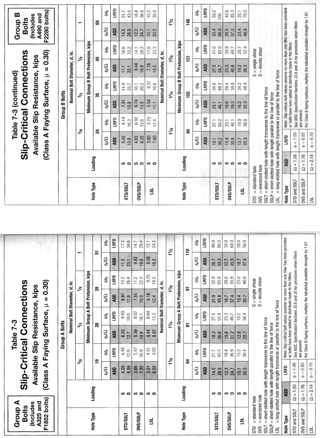
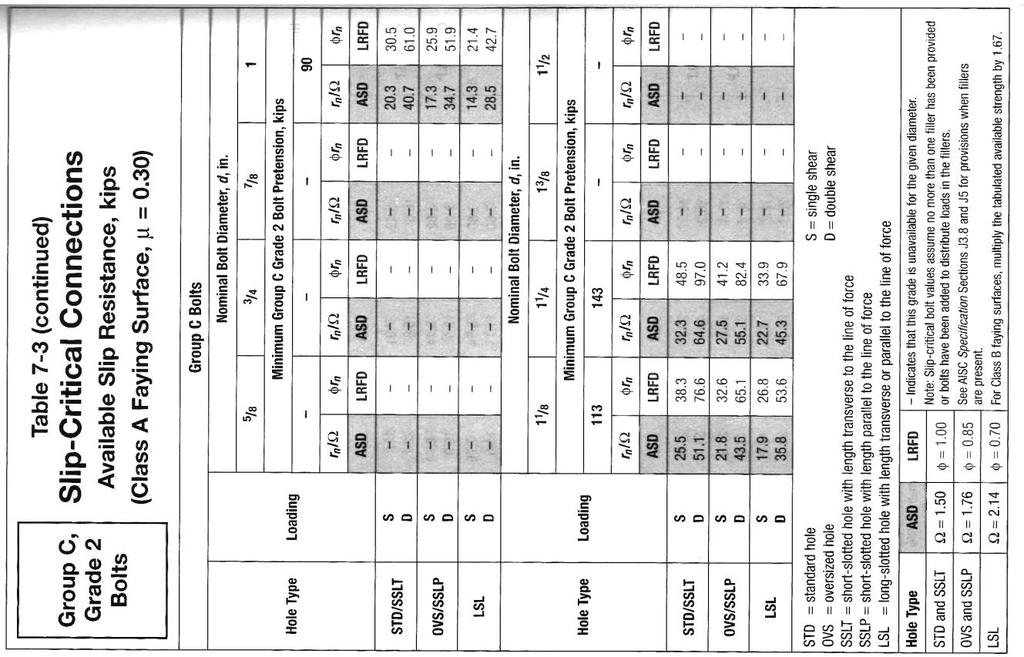
18 Bolted and Welded Connections The limit state for connections depends on the loads: 1. tension yielding 2. shear yielding 3. bearing yielding 4. bending yielding due to eccentric loads 5. rupture Welds must resist shear stress. The design strengths depend on the weld materials. Bolted Connection Design Bolt designations signify material and type of connection where SC: slip critical N: bearing-type connection with bolt threads included in shear plane X: bearing-type connection with bolt threads excluded from shear plane A307: similar in strength to A36 steel (also known as ordinary, common or unfinished bolts) ASTM F3125 Grade A325: high strength bolts (Group A) ASTM F3125 Grade A490: high strength bolts (higher than A325) (Group B) ASTM F3043 and ASTM F3111 (Group C) Bearing-type connection: no frictional resistance in the contact surfaces is assumed and slip between members occurs as the load is applied. (Load transfer through bolt only). Slip-critical connections: bolts are torqued to a high tensile stress in the shank, resulting in a clamping force on the connected parts. (Shear resisted by clamping force). Requires inspections and is useful for structures seeing dynamic or fatigue loading. Class A indicates the faying (contact) surfaces are clean mill scale or adequate paint system, while Class B indicates blast cleaning or paint for = Bolts rarely fail in bearing. The material with the hole will more likely yield first. For the determination of the net area of a bolt hole the width is taken as 1/16 greater than the nominal dimension of the hole. Standard diameters for bolt holes are 1/16 larger than the bolt diameter. (This means the net width will be 1/8 larger than the bolt.) Design for Bolts in Bearing, Shear and Tension Available shear values are given by bolt type, diameter, and loading (Single or Double shear) in AISC manual tables. Available shear value for slip-critical connections are given for limit states of serviceability or strength by bolt type, hole type (standard, short-slotted, long-slotted or 328
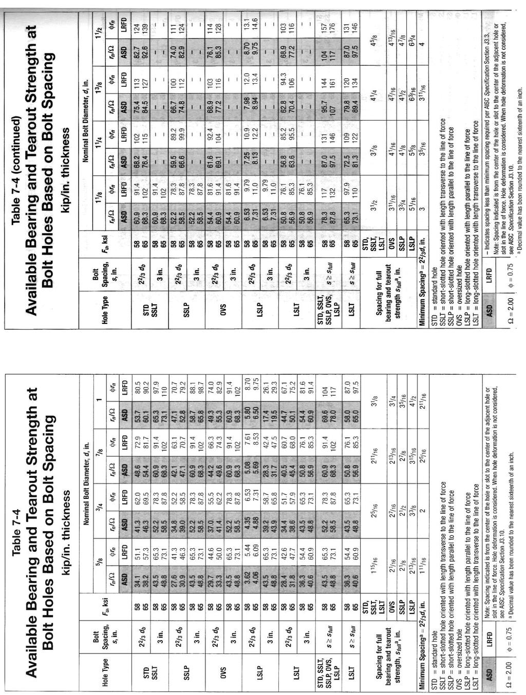
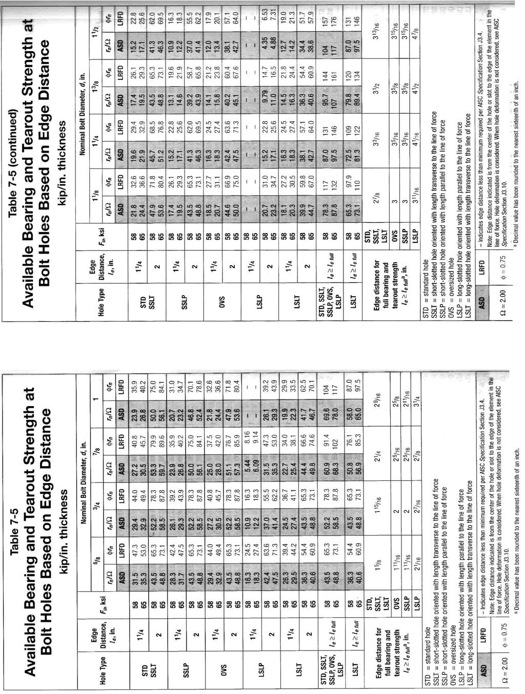
19 oversized), diameter, and loading. Available tension values are given by bolt type and diameter in AISC manual tables. The values are provide per bolt, n, and for a set of bolts. Rn rnn Available bearing force values are given by bolt diameter, ultimate tensile strength, Fu, of the connected part, and thickness of the connected part in AISC manual tables. The values are provide per bolt per inch of thickness, n, and for a set of bolts. For shear OR tension (same equation) in bolts: Ra Rn / or where single shear (or tension) R F A n n b double shear R F 2A where n n b R R n r nt n R u R u i i = the resistance factor Fn = the nominal tension or shear strength of the bolt Ab = the cross section area of the bolt = 0.75 (LRFD) = 2.00 (ASD) R For bearing of plate material at bolt holes: Ra Rn / or Ru Rn where Ru iri deformation at bolt hole is a concern R 1.2L tf 2.4dtF n c u u deformation at bolt hole is not a concern R 1.5L tf 3.0dtF n c u u long slotted holes with the slot perpendicular to the load where R 1.0L tf 2.0dtF n c u u Rn = the nominal bearing strength Fu = specified minimum tensile strength Lc = clear distance between the edges of the hole and the next hole or edge in the direction of the load d = nominal bolt diameter t = thickness of connected material = 0.75 (LRFD) = 2.00 (ASD) The minimum edge desistance from the center of the outer most bolt to the edge of a member is generally 1¾ times the bolt diameter for the sheared edge and 1¼ times the bolt diameter for the rolled or gas cut edges. The maximum edge distance should not exceed 12 times the thickness of thinner member or 6 in. Standard bolt hole spacing is 3 in. with the minimum spacing of times the diameter of the bolt, db. Common edge distance from the center of last hole to the edge is 1¼ in. n 329
20 Tension Member Design In steel tension members, there may be bolt holes that reduce the size of the cross section. g refers to the row spacing or gage p refers to the bolt spacing or pitch s refers to the longitudinal spacing of two consecutive holes Effective Net Area: The smallest effective area must be determined by subtracting the bolt hole areas. With staggered holes, the shortest length must be evaluated. A series of bolts can also transfer a portion of the tensile force, and some of the effective net areas see reduced stress. The effective net area, Ae, is determined from the net area, An, multiplied by a shear lag factor, U, which depends on the element type and connection configuration. If a portion of a connected member is not fully connected (like the leg of an angle), the unconnected part is not subject to the full stress and the shear lag factor can range from 0.6 to 1.0: Ae AnU The staggered hole path area is determined by: A A n g A of all holes 2 s t 4g where t is the plate thickness, s is each stagger spacing, and g is the gage spacing. For tension elements: R R / or R R 1. yielding R F A a n y g n where = 0.90 (LRFD) = 1.67 (ASD) R u R u i i n 330
21 2. rupture R F A = 0.75 (LRFD) n u e = 2.00 (ASD) where Ag = the gross area of the member (excluding holes) Ae = the effective net area (with holes, etc.) Fy = the yield strength of the steel Fu = the tensile strength of the steel (ultimate) Welded Connections Weld designations include the strength in the name, i.e. E70XX has Fy = 70 ksi. Welds are weakest in shear and are assumed to always fail in the shear mode. The throat size, T, of a fillet weld is determined trigonometry by: T = weld size* * When the submerged arc weld process is used, welds over 3/8 will have a throat thickness of 0.11 in. larger than the formula. Weld sizes are limited by the size of the parts being put together and are given in AISC manual table J2.4 along with the allowable strength per length of fillet weld, referred to as S. The maximum size of a fillet weld: a) can t be greater than the material thickness if it is ¼ or less b) is permitted to be 1/16 less than the thickness of the material if it is over ¼ The minimum length of a fillet weld is 4 times the nominal size. If it is not, then the weld size used for design is ¼ the length. Intermittent fillet welds cannot be less than four times the weld size, not to be less than 1 ½. 331
22 For fillet welds: R R / or R R a n where R u R u i i for the weld metal: R 0.6F Tl Sl where: n = 0.75 (LRFD) T is throat thickness l is length of the weld EXX = 2.00 (ASD) For a connected part, the other limit states for the base metal, such as tension yield, tension rupture, shear yield, or shear rupture must be considered. n Available Strength of Fillet Welds per inch of weld (S) Weld Size (in.) E60XX (k/in.) E70XX (k/in.) ¼ ½ ¾ (not considering increase in throat with submerged arc weld process) Framed Beam Connections Coping is the term for cutting away part of the flange to connect a beam to another beam using welded or bolted angles. AISC provides tables that give bolt and angle available strength knowing number of bolts, bolt type, bolt diameter, angle leg thickness, hole type and coping, and the wide flange beam being connected. For the connections the limit-state of bolt shear, bolts bearing on the angles, shear yielding of the angles, shear rupture of the angles, and block shear rupture of the angles, and bolt bearing on the beam web are considered. Group A bolts include A325, while Group B includes A490. There are also tables for bolted/welded double-angle connections and all-welded double-angle connections. 332

23 Limiting Strength or Stability States In addition to resisting shear and tension in bolts and shear in welds, the connected materials may be subjected to shear, bearing, tension, flexure and even prying action. Coping can significantly reduce design strengths and may require web reinforcement. All the following must be considered: shear yielding shear rupture block shear rupture - failure of a block at a beam as a result of shear and tension tension yielding tension rupture local web buckling lateral torsional buckling Sample AISC Table for Bolt and Angle Available Strength in All-Bolted Double-Angle Connections Block Shear Strength (or Rupture): where: R R / or R R a where n R R u i i u R 0.6F A U F A 0.6F A U F A n n u nv bs u nt y gv bs u nt = 0.75 (LRFD) = 2.00 (ASD) Anv is the net area subjected to shear Ant is the net area subjected to tension Agv is the gross area subjected to shear Ubs = 1.0 when the tensile stress is uniform (most cases) = 0.5 when the tensile stress is non-uniform 333
24 Gusset Plates Gusset plates are used for truss member connections where the geometry prevents the members from coming together at the joint point. Members being joined are typically double angles. Decking Shaped, thin sheet-steel panels that span several joists or evenly spaced support behave as continuous beams. Design tables consider a 1 unit wide strip across the supports and determine maximum bending moment and deflections in order to provide allowable loads depending on the depth of the material. The other structural use of decking is to construct what is called a diaphragm, which is a horizontal unit tying the decking to the joists that resists forces parallel to the surface of the diaphragm. When decking supports a concrete topping or floor, the steel-concrete construction is called composite. Frame Columns Because joints can rotate in frames, the effective length of the column in a frame is harder to determine. The stiffness (EI/L) of each member in a joint determines how rigid or flexible it is. To find k, the relative stiffness, G or, must be found for both ends, plotted on the alignment charts, and connected by a line for braced and unbraced fames. EI lc G where E = modulus of elasticity for a member I = moment of inertia of for a member lc = length of the column from center to center lb = length of the beam from center to center EI l b For pinned connections we typically use a value of 10 for. For fixed connections we typically use a value of 1 for. Braced non-sway frame Unbraced sway frame 334
25 335
 F y = 50 ksi 1,000+50=1,050 lb/ft = 1.")
26 Example 1 (pg 412) *Hypothetically determine the size of section required when the deflection criteria is NOT met *(unified ASD) F y = 50 ksi 1,000+50=1,050 lb/ft = 1.05 k/ft 336
27 Example 2 Use ASD of the Unified Design method. 1. The unbraced length is 0 because it says it is fully braced. 2. Find the maximum shear and moment from unfactored loads: wa = k/ft k/ft = 1.20 k/ft 3. Find Zreq d: Va = 1.20 k/ft(35 ft)/2 = 21 k Ma = 1.20 k/ft(35 ft) 2 /8 = 184 k-ft If Ma Mn/Ω, the maximum moment for design is MaΩ: Mmax = 184 k-ft Zreq d Mmax/Fb = Mmax(Ω)/Fy = 184 k-ft(1.67)(12 in/ft)/50 ksi = in 3 4. Choose a trial section, and also limit the depth to 18 in as instructed: 337 (Fy is the limit stress when fully braced) W18 x 40 has a plastic section modulus of 78.4 in 3 and is the most light weight (as indicated by the bold text) in Table 9.1 Include the self weight in the maximum values: Zreq d k-ft(1.67)(12 in/ft)/50 ksi = in 3 w*a-adjusted = 1.20 k/ft k/ft V*a-adjusted = 1.24 k/ft(35 ft)/2 = 21.7 k M*a-adjusted = 1.24 k/ft(35 ft) 2 /8 = k And the Z we have (78.4) is larger than the Z we need (76.11), so OK. 6. Evaluate shear (is Va Vn/Ω): Aw = dtw so look up section properties for W18 x 40: d = in and tw = in Vn/Ω = 0.6FywAw/Ω = 0.6(50 ksi)(17.90 in)(0.315 in)/1.5 = k which is much larger than 21.7 k, so OK. 9. Evaluate the deflection with respect to the limit stated of L/360 for the live load. (If we knew the total load limit we would check that as well). The moment of inertia for the W18 x 40 is needed. Ix = 612 in 4 live load limit = 35 ft(12 in/ft)/360 = 1.17 in = 5wL 4 /384EI = 5(0.75 k/ft)(35 ft) 4 (12 in/ft) 3 /384(29 x 10 3 ksi)(612 in 4 ) = 1.42 in! This is TOO BIG (not less than the limit. Find the moment of inertia needed: Ireq d too big (Itrial)/limit = 1.42 in(612 in 4 )/(1.17 in) = in 4 From the Listing of W Shapes in Descending order of Zx for Beam Design, a W21 x 44 is larger (by Ix = 843 in 4 ), and the most light weight, but it is too deep!. In the next group up, the W16 x 57 works (Ix = 758 in 4, but we aren t certain there is a more economical section. Then W18x50, W12x72, and W18x55, so we stop because the W18x50 has the smallest weight with the depth restriction. (In order: Ix = 800, 597, and 890 in 4 ) Choose a W18 x 50
20k = 32k (1.2)1k/ft = 1.2k/ft 32.8k -32.8k 341.6 k-ft 1.")
28 Example 3 For the same beam and loading of Example 1, select the most economical beam using Load and Resistance Factor Design (LRFD) with the 18 depth restriction. Assume the distributed load is dead load, and the point load is live load. F y = 50 ksi and E = 30x10 3 ksi 32.8k +32.8k -16 k +16k (1.6)20k = 32k (1.2)1k/ft = 1.2k/ft 32.8k -32.8k k-ft 1. To find Vu-max and Mu-max, factor the loads, construct a new load diagram, shear diagram and bending moment diagram. 2. To satisfy Mu bmn, we find and solve for Z needed: Choose a trial section from the Listing of W Shapes in Descending Order of Z by selecting the bold section at the top of the grouping satisfying our Z and depth requirement W16 x 50 is the lightest with Z = 92 in 3. (W21 x 44 is the lightest without the depth requirement.) Include the additional self weight (dead load) and find the maximum shear and bending moment:, so Z (have) of 92 in 3 is NOT greater than the Z (needed). Choose the next lightest weight section with depth within the limit W18 x 50 is the same weight with Z = 101 in 3. If the weight was different, the additional distributed load would have to be included to find V*uadjusted, M*u-adjusted, and Z*req d. 3. Check the shear capacity to satisfy Vu vvn: Aweb = dtw and d=17.99 in., tw = in. for the W18x50 So k k OK 4. Calculate the deflection from the unfactored loads, including the self-weight now because it is known, and satisfy the deflection criteria of LL LL-limit and total total-limit. (This is identical to what is done in Example 1.) Ix =800 in 3 for the W18 x 50 total-limit = L/240 = 1.4 in., and we don t know the live load limit, but we ll assume LL = 0.60 in (for ex.) So 1.26 in. 1.4 in. is true (OK) State: USE W18 x 50 *NOTE: If we knew which part of the load was live load, we would also have to compare the live load deflection with the live load deflection limit. To illustrate what we would have to do if the deflection check was not OK, lets assume the point load is live load and the limit is 0.6 in.: So in. 0.6 in. NOT OK We need to choose a larger section: using 338 The section that would satisfy this is a W18x55. (I = 890 in 4 ) With the additional weight, adjusted values should be checked.

29 Example 4 A steel beam with a 20 ft span is designed to be simply supported at the ends on columns and to carry a floor system made with open-web steel joists at 4 ft on center. The joists span 28 feet and frame into the beam from one side only and have a self weight of 8.5 lb/ft. Use A992 (grade 50) steel and select the most economical wide-flange section for the beam with LRFD design. Floor loads are 50 psf LL and 14.5 psf DL
 The beam is a roof beam for an institution without plaster ceilings.")
: w = 1.2(825 lb/ft)+1.6(1300 lb/ft) =3.")
30 Example 5 Select a A992 W shape flexural member (F y = 50 ksi, F u = 65 ksi) for a beam with distributed loads of 825 lb/ft (dead) and 1300 lb/ft (live) and a live point load at midspan of 3 k using the Available Moment tables. The beam is cantilevered, 20 feet long, and braced at the ends and midpoint only (L b = 10 ft.) The beam is a roof beam for an institution without plaster ceilings. (LRFD) SOLUTION: 1.6(3k) =4.8k To use the Available Moment tables, the maximum moment required is plotted against the unbraced length. The first solid line with capacity or unbraced length above what is needed is the most economical. DESIGN LOADS (load factors applied on figure): w = 1.2(825 lb/ft)+1.6(1300 lb/ft) =3.07k/ft Plotting 662 k-ft vs. 10 ft lands just on the capacity of the W21x83, but it is dashed (and not the most economical) AND we need to consider the contribution of self weight to the total moment. Choose a trial section of W24 x 76. Include the new dead load: Replot k-ft vs. 10ft, which lands above the capacity of the W21x83. We can t look up because the chart ends, but we can look for that capacity with a longer unbraced length. This leads us to a W24 x 84 as the most economical. (With the additional self weight of lb/ft = 8 lb/ft, the increase in the factored moment is only 1.92 k-ft; therefore, it is still OK.) Evaluate the shear capacity: so yes, 68 k 338.4k OK Evaluate the deflection with respect to the limits of L/240 for live (unfactored) load and L/180 for total (unfactored) load: L/240 = 1 in. and L/180 = 1.33 in w = 825 lb/ft lb/ft + 84 lb/ft =2.209k/ft + So, LL LL-limit and total total-limit: in. 1 in. and 0.42 in in. (This section is so big to accommodate the large bending moment at the cantilever support that it deflects very little.) FINAL SELECTION IS W24x84 340

.")
 values are")
31 Example 6 Select the most economical joist for the 40 ft grid structure with floors and a flat roof. The roof loads are 10 lb/ft 2 dead load and 20 lb/ft 2 live load. The floor loads are 30 lb/ft 2 dead load 100 lb/ft 2 live load. (Live load deflection limit for the roof is L/240, while the floor is L/360). Use the (LRFD) K and LH series charts provided. (Top values are maximum total factored load in lb/ft, while the lower (lighter) values are maximum (unfactored) live load for a deflection of L/360) 341 Shaded areas indicate the bridging requirements.
")
 342 Shaded areas indicate the")
32 Example 6 (continued) (Top values are maximum total factored load in lb/ft, while the lower (lighter) values are maximum (unfactored) live load for a deflection of L/360) 342 Shaded areas indicate the bridging requirements.
 + 1.6 (57.2) = 158.2 plf 223 plf TFL and 77 plf LL total = 158.2 plf - 1.2(9-6.4 plf) = 154.1 plf < 233 plf 6.4 plf 6.5 plf 7.")
33 Example 7 (LRFD) Total dead load Total live load 13.9 psf X 4 ft o.c. = 55.6 plf Total factored live snow load + dead load = 1.2(55.6) (57.2) = plf 223 plf TFL and 77 plf LL total = plf - 1.2(9-6.4 plf) = plf < 233 plf 6.4 plf 6.5 plf 7.3 plf 343
34 Example 8 A floor with multiple bays is to be supported by open-web steel joists spaced at 3 ft. on center and spanning 30 ft. having a dead load of 70 lb/ft 2 and a live load of 100 lb/ft 2. The joists are supported on joist girders spanning 30 ft. with 3 ft.-long panel points (shown). Determine the member forces at the location shown in a horizontal chord and the maximum force in a web member for an interior girder. Use factored loads. Assume a self weight for the openweb joists of 12 lb/ft, and the self weight for the joist girder of 35 lb/ft. 344
35 Example 9 A floor is to be supported by trusses spaced at 5 ft. on center and spanning 60 ft. having a dead load of 53 lb/ft 2 and a live load of 100 lb/ft 2. With 3 ft.-long panel points, the depth is assumed to be 3 ft with a span-to-depth ratio of 20. With 6 ft.-long panel points, the depth is assumed to be 6 ft with a span-to-depth ratio of 10. Determine the maximum force in a horizontal chord and the maximum force in a web member. Use factored loads. Assume a self weight of 40 lb/ft. tributary widths wdead area loads wlive Pdead (=wdead A) (K) Plive (=wlive A) (K) = = 7.00 self weight 0.04 k/ft (distributed) 3 1.2Pdead = 1.2wdead tributary width = 0.14 K 6 1.2Pdead = 1.2wdead tributary width = 0.29 K NOTE end panels only have half the tributary width of interior panels A B FBD 1 for 3 ft deep truss FBD 3: Maximum web force will be in the end diagonal (just like maximum shear in a beam) Fy = 10P1 0.5P1 FABsin45 = 0 FAB = 9.5P1/sin45 = 9.5(3.49 k)/0.707 = 46.9 k FBD 2: Maximum chord force (top or bottom) will be at midspan G FAB MG = -9.5P1(27 ft ) + P1(24 ft ) + P1(21 ft ) + P1(18 ft ) + P1(15 ft ) + P1(12 ft ) + P1(9 ft ) + P1(6 ft ) + P1(3 ft ) + T1(3 ft ) = 0 T1 = P1(148.5 ft )/3 ft = (3.49 k)(49.5) = k FBD 2 of cut just to the left of midspan FBD 3 of cut just to right of left support Fy = 10P1 9.5P1 D1sin45 = 0 D1 = 0.5(3.49 k)/0.707 = 2.5 k (minimum near midspan) Fx =-C1 + T1 + D1cos45 = 0 C1 = k A FBD 6: Maximum web force will be in the end diagonal B FBD 4 for 6 ft deep truss G FBD 5 of cut just to the left of midspan FAB FBD 6 of cut just to right of left support 345 Fy = 5P2 0.5P2 FABsin45 = 0 FAB = 4.5P2/sin45 = 4.5(7 k)/0.707 = 44.5 k FBD 5: Maximum chord (top or bottom) force will be at midspan MG = -4.5P2(24 ft ) + P2(18 ft ) + P2(12 ft ) + P2(6 ft ) + T2(6 ft ) = 0 T2 = P2(72 ft )/6 ft = (7 k)(12) = 84 k Fy = 5P2 4.5P1 Dssin45 = 0 D2 = 0.5(7 k)/0.707 = 4.9 k (minimum near midspan) Fx =-C2 + T2 + D2cos45 = 0 C2 = 87.5 k
 + chart method Use LRFD assuming that the")
 ALSO: Select the W12 column using the Available")
36 Example 10* (pg 464) Unified ASD + LRFD Example 11* (pg 469) + chart method Use LRFD assuming that the load is a dead load (factor of 1.4) ALSO: Select the W12 column using the Available Strength charts. 346
37 Example 12 Use both ASD and LRFD. Fy = 50 ksi. (Not using Available Strength charts) Solution: ASD: 1. Pa = 140 k k = 560 k 2. The effective length in the weak (y-y) axis is 15 ft, while the effective length in the strong (x-x) axis is 30 ft. (K = 1, KL = 1 30 ft). To find kl/rx and kl/ry we can assume or choose values from the wide flange charts. ry s range from 1 to 3 in., while rx s range from 3 to 14 inches. Let s try ry = 2 in and rx = 9 in. (something in the W21 range, say.) kl/ry 15 ft(12 in/ft)/2 in. = 90 GOVERNS (is larger) kl/rx 30 ft(12 in/ft)/9 in. = Find a section with sufficient area (which then will give us real values for rx and ry): If Pa Pn/Ω, and Pn = Fcr A, we can find A PaΩ/Fcr with Ω = 1.67 The tables provided have Fcr, so we can get Fcr by dividing by = 0.9 Fcr for 90 is 24.9 ksi, Fcr = 24.9 ksi/0.9 = ksi so A 560 k(1.67)/27.67 ksi = 33.8 in 2 4. Choose a trial section, and find the effective lengths and associated available strength, Fcr : Looking from the smallest sections, the W14 s are the first with a big enough area: Try a W14 x 120 (A = 35.3 in 2 ) with ry = 3.74 in and rx = 6.24 in.: Fcr for 58 is 35.2 ksi, Fcr = 39.1 ksi so A 560 k(1.67)/39.1 ksi = 23.9 in 2 kl/ry = 48.1 and kl/rx = 57.7 (GOVERNS) Choose a W14 x 90 (Choosing a W14 x 82 would make kl/rx = 59.5, and Areq d = 24.3 in 2, which is more than 24.1 in 2!) LRFD: 1. Pu = 1.2(140 k) + 1.6(420 k) = 840 k 2. The effective length in the weak (y-y) axis is 15 ft, while the effective length in the strong (x-x) axis is 30 ft. (K = 1, KL = 1 30 ft). To find kl/rx and kl/ry we can assume or choose values from the wide flange charts. ry s range from 1 to 3 in., while rx s range from 3 to 14 inches. Let s try ry = 2 in and rx = 9 in. (something in the W21 range, say.) kl/ry 15 ft(12 in/ft)/2 in. = 90 GOVERNS (is larger) kl/rx 30 ft(12 in/ft)/9 in. = Find a section with sufficient area (which then will give us real values for rx and ry): If Pu Pn, and Pn = Fcr A, we can find A Pu/Fcr with = 0.9 Fcr for 90 is 24.9 ksi, so A 840 k/24.9 ksi = 33.7 in 2 4. Choose a trial section, and find the effective lengths and associated available strength, Fcr : Looking from the smallest sections, the W14 s are the first with a big enough area: Try a W14 x 120 (A = 35.3 in 2 ) with ry = 3.74 in and rx = 6.24 in.: Fcr for 58 is 35.2 ksi, so A 840 k/35.2 ksi = 23.9 in kl/ry = 48.1 and kl/rx = 57.7 (GOVERNS) Choose a W14 x 90 (Choosing a W14 x 82 would make kl/rx = 59.5, and Areq d = 24.3 in 2, which is more than 24.1 in 2!)
38 Example
: Axial load = 1.2(0.25)(350k)+1.6(0.")
39 Example 14 Investigate the accepatbility of a W16 x 67 used as a beam-column under the unfactored loading shown in the figure. It is A992 steel (F y = 50 ksi). Assume 25% of the load is dead load with 75% live load. SOLUTION: DESIGN LOADS (shown on figure): Axial load = 1.2(0.25)(350k)+1.6(0.75)(350k)=525k Moment at joint = 1.2(0.25)(60 k-ft ) + 1.6(0.75)(60 k-ft ) = 90 k-ft Determine column capacity and fraction to choose the appropriate interaction equation: and (governs) 525 k 90 k-ft 525 k 90 k-ft so use There is no bending about the y axis, so that term will not have any values. Determine the bending moment capacity in the x direction: Using the Available Strength Table 6-2, we can determine the available compressive strength for the unbraced length that governs (ry) of 15ft too. It is listed as 596 k (not significantly different). We also can find the value of Mn at Lb =15 ft, listed as 422 k-ft. This is the braced moment of Mnt for the x axis. Mr = B1Mnt, so we need to know B1 the moment magnification factor - for the x axis: Determine the magnification factor when M1 = 0, M2 = 90 k-ft: 525 k 525 k USE 1.0 Mrx = B1(Mnt) = (1)90 k-ft Finally, determine the interaction value: This is NOT OK. (and outside error tolerance). The section should be larger. 349
40 Example 15 * (pg 530) available ^, assuming A36 steel with E60XX electrodes. Example 16 * (pg526) available ^ S = 6.96 k/in 8 in + 6 in + 8 in = 22 in k/in = k Pn = FyAg = x 36 k/in 2 x 3/8 x 6 = 72.9 k Pn = 72.9 k 72.9 k 72.9 k 3.31 k/in. From Available Strength table, use 3/16 weld (S = 4.18 k/in.) 350
41 Example 17 * (pg 517) 7-1, required? Also determine the bearing capacity of the wide flange sections. Factored end beam reaction = 60 k = 90 k. tf = in. Fu = 65 ksi Example 18 Verify the tensile strength of an L4 x 4 x ½, ASTM 36, with one line of (4) ½ in.-diameter bolts and standard holes. The member carries a dead load of 20 kips and a live load of 60 kips in tension. Assume that connection limit states do not govern, and U =
.")
42 Example 19 The steel used in the connection and beams is A992 with F y = 50 ksi, and F u = 65 ksi. Using A490-N bolt material, determine the maximum capacity of the connection based on shear in the bolts, bearing in all materials and pick the number of bolts and angle length (not staggered). Use A36 steel for the angles. W21x93: d = in, t w = 0.58 in, t f = 0.93 in W10x54: t f = in SOLUTION: The maximum length the angles can be depends on how it fits between the top and bottom flange with some clearance allowed for the fillet to the flange, and getting an air wrench in to tighten the bolts. This example uses 1 of clearance: Available length = beam depth both flange thicknesses 1 clearance at top & 1 at bottom = in 2(0.93 in) 2(1 in) = in. With the spaced at 3 in. and 1 ¼ in. end lengths (each end), the maximum number of bolts can be determined: Available length 1.25 in in. + 3 in. x (number of bolts 1) It is helpful to have the All-bolted Double-Angle Connection Tables They are available for ¾, 7/8, and 1 bolt diameters and list angle thicknesses of ¼, 5/16, 3/8, and ½. Increasing the angle thickness is likely to increase the angle strength, although the limit states include shear yielding of the angles, shear rupture of the angles, and block shear rupture of the angles. For these diameters, the available shear (double) from Table 7-1 for 6 bolts is (6)45.1 k/bolt = kips, (6)61.3 k/bolt = kips, and (6)80.1 k/bolt = kips. Tables 10-1 (not all provided here) lists a bolt and angle available strength of 269 kips for the ¾ bolts, 297 kips for the 7/8 bolts, and 271 kips for the 1 bolts. It appears that increasing the bolt diameter to 1 will not gain additional load. Use 7/8 bolts. number of bolts (17.76 in 2.5 in. - (-3 in.))/3 in. = 6.1, so 6 bolts. Rn = kips for double shear of 7/8 bolts 352 Rn = 297 kips for limit state in angles We also need to evaluate bearing of bolts on the beam web, and column flange where there are bolt holes. Table 7-4 provides available bearing strength for the material type, bolt diameter, hole type, and spacing per inch of material thicknesses. a) Bearing for beam web: There are 6 bolt holes through the beam web. This is typically the critical bearing limit value because there are two angle legs that resist bolt bearing and twice as many bolt holes to the column. The material is A992 (Fu = 65 ksi), 0.58 thick, with 7/8 bolt diameters at 3 in. spacing. Rn = 6 bolts(102 k/bolt/inch)(0.58 in) = kips b) Bearing for column flange: There are 12 bolt holes through the column. The material is A992 (Fu = 65 ksi), thick, with 1 bolt diameters. Rn = 12 bolts(102 k/bolt/inch)(0.615 in) = kips Although, the bearing in the beam web is the smallest at 355 kips, with the shear on the bolts even smaller at kips, the maximum capacity for the simple-shear connector is 296 kips limited by the critical capacity of the angles.
: Rn = 26.4 k/bolt x 4 bolts = 105.")
43 3.5 in ARCH 331 Note Set 18 F2018abn Example 20 * (pg 508) SOLUTION: available Shear, bearing and net tension will be checked to determine the critical conditions that governs the capacity of the connection. Shear: Using the AISC available shear in Table 7-3 (Group A): Rn = 26.4 k/bolt x 4 bolts = k Bearing: Using the AISC available bearing in Table 7-4: There are 4 bolts bearing on the center (1/2 ) plate, while there are 4 bolts bearing on a total width of two sandwich plates (3/4 total). The thinner bearing width will govern. Assume 3 in. spacing (center to center) of bolts. For A36 steel, Fu = 58 ksi. Rn = 91.4 k/bolt/in. x 0.5 in. x 4 bolts = k (Table 7-4) With the edge distance of 2 in., the bearing capacity might be smaller from Table 7-5 which says the distance should be 2 ¼ in for full bearing (and we have 2 in.). Rn = 79.9 k/bolt/in. x 0.5 in. x 4 bolts = k Tension: The center plate is critical, again, because its thickness is less than the combined thicknesses of the two outer plates. We must consider tension yielding and tension rupture: Rn =FyAg and Rn =FuAe where Ae = AnetU 1 " 8 Ag = 8 in. x ½ in. = 4 in 2 The holes are considered 1/8 in. larger than the bolt hole diameter = (7/8 + 1/8) = 1.0 in. An = (8 in. 2 holes x 1.0 in.) x ½ in. = 3.0 in 2 The whole cross section sees tension, so the shear lag factor U = 1 FyAg = 0.9 x 36 ksi x 4 in 2 = k FuAe = 0.75 x 58 ksi x (1) x 3.0 in 2 = k 4 in. 2 in. The maximum connection capacity (smallest value) so far is governed by bolt shear: Block Shear Rupture: It is possible for the center plate to rip away from the sandwich plates leaving the block (shown hatched) behind: Rn =(0.6FuAnv + UbsFuAnt) (0.6FyAgv + UbsFuAnt) Rn = k where Anv is the area resisting shear, Ant is the area resisting tension, Agv is the gross area resisting shear, and Ubs = 1 when the tensile stress is uniform. Agv = 2 x (4 + 2 in.) x ½ in. = 6 in 2 Anv = Agv 1 ½ holes areas x 2 sides = 6 in x 1 in. x ½ in. x 2 = 4.5 in 2 Ant = 3.5 in. x t 2(½ hole areas) = 3.5 in. x ½ in 1 x 1 in. x ½ in. = 1.25 in 2 (0.6FuAnv + UbsFuAnt) = 0.75 x (0.6 x 58 ksi x 4.5 in x 58 ksi x 1.25 in 2 ) = k (0.6FyAgv + UbsFuAnt) = 0.75 x (0.6 x 36 ksi x 6 in x 58 ksi x 1.25 in 2 ) = k governs (< k) The maximum connection capacity (smallest value) is governed by bolt shear (from the boxed values): Rn = k 353
44 Listing of W Shapes in Descending order of Zx for Beam Design Z x US (in. 3 ) I x US (in. 4 ) Section I x SI (10 6 mm. 4 ) Z x SI (10 3 mm.3) 354 Z x US (in. 3 ) I x US (in. 4 ) Section I x SI (10 6 mm. 4 ) Z x SI (10 3 mm.3) W33X W24X W24X W14X W36X W30X W30X W24X W18X W21X W14X W27X W12X W12X W21X W18X W24X W14X W33X W24X W27X W21X W18X W27X W30X W12X W14X W14X W21X W18X W12X W24X W24X W21X W33X W12X W30X W14X W18X W18X W27X W24X W14X W16X W12X W21X W30X W14X W21X W18X W24X W12X W18X W24X W14X W16X W12X W14X W30X W21X W27X W12X W21X W18X W24X W21X W18X W14X W14X W24X W30X W16X W12X W12X W21X W10X W27X W18X W18X (continued)
45 Listing of W Shapes in Descending order of Zx for Beam Design (Continued ) Z x US (in. 3 ) I x US (in. 4 ) Section I x SI (10 6 mm. 4 ) Z x SI (10 3 mm.3) Z x US (in. 3 ) I x US (in. 4 ) Section I x SI (10 6 mm. 4 ) Z x SI (10 3 mm.3) W21X W18X W14X W12X W24X W16X W18X W14X W12X W10X W16X W8X W10X W12X W21X W10X W21X W14X W14X W16X W18X W12X W12X W8X W14X W14X W10X W10X W18X W16X W21X W12X W12X W14X W21X W8X W16X W10X W14X W12X W18X W10X W10X W8X W12X W14X W21X W10X W16X W8X W18X W12X W14X W8X W12X W10X W10X W12X W16X W8X W18X W10X W14X W8X W12X W12x W10X W10X W16X W12X W12X W8X W8X W10X W14X W8X W10X W10X W8X W8X
46 Available Critical Stress, cfcr, for Compression Members, ksi (Fy = 36 ksi and c = 0.90) KL/r c F cr KL/r c F cr KL/r c F cr KL/r c F cr KL/r c F cr
47 Available Critical Stress, cfcr, for Compression Members, ksi (Fy = 50 ksi and c = 0.90) KL/r c F cr KL/r c F cr KL/r c F cr KL/r c F cr KL/r c F cr

48 Bolt Strength Tables 358
49 359
50 360
51 361
52 362
Steel Design. Notation:
 Steel Design Notation: a A A b A e A g A gv A n A nt A nv A w = name for width dimension = name for area = area of a bolt = effective net area found from the product of the net area A n by the shear lag
Beam Design and Deflections
 Beam Design and Deflections tation: a = name for width dimension A = name for area Areq d-adj = area required at allowable stress when shear is adjusted to include self weight Aweb = area of the web of
Steel Design. Notation: a A A b A e
 Steel Design Notation: a A A b A e A g A gv A n A nt A nv A w = name for width dimension = name for area = area of a bolt = effective net area found from the product of the net area A n by the shear lag
Karbala University College of Engineering Department of Civil Eng. Lecturer: Dr. Jawad T. Abodi
 Chapter 05 Structural Steel Design According to the AISC Manual 13 th Edition Analysis and Design of Beams By Dr. Jawad Talib Al-Nasrawi University of Karbala Department of Civil Engineering 71 Introduction
Karbala University College of Engineering Department of Civil Eng. Lecturer: Dr. Jawad T. Abodi
 Chapter 04 Structural Steel Design According to the AISC Manual 13 th Edition Analysis and Design of Compression Members By Dr. Jawad Talib Al-Nasrawi University of Karbala Department of Civil Engineering
Accordingly, the nominal section strength [resistance] for initiation of yielding is calculated by using Equation C-C3.1.
![Accordingly, the nominal section strength [resistance] for initiation of yielding is calculated by using Equation C-C3.1.](/thumbs/89/98617066.jpg "Accordingly, the nominal section strength [resistance] for initiation of yielding is calculated by using Equation C-C3.1.") C3 Flexural Members C3.1 Bending The nominal flexural strength [moment resistance], Mn, shall be the smallest of the values calculated for the limit states of yielding, lateral-torsional buckling and distortional
C3 Flexural Members C3.1 Bending The nominal flexural strength [moment resistance], Mn, shall be the smallest of the values calculated for the limit states of yielding, lateral-torsional buckling and distortional
Wood Design. fv = shear stress fv-max = maximum shear stress Fallow = allowable stress Fb = tabular bending strength = allowable bending stress
 Wood Design Notation: a = name for width dimension A = name for area Areq d-adj = area required at allowable stress when shear is adjusted to include self weight b = width of a rectangle = name for height
Failure in Flexure. Introduction to Steel Design, Tensile Steel Members Modes of Failure & Effective Areas
 Introduction to Steel Design, Tensile Steel Members Modes of Failure & Effective Areas MORGAN STATE UNIVERSITY SCHOOL OF ARCHITECTURE AND PLANNING LECTURE VIII Dr. Jason E. Charalambides Failure in Flexure!
MODULE C: COMPRESSION MEMBERS
 MODULE C: COMPRESSION MEMBERS This module of CIE 428 covers the following subjects Column theory Column design per AISC Effective length Torsional and flexural-torsional buckling Built-up members READING:
Mechanics of Materials Primer
 Mechanics of Materials rimer Notation: A = area (net = with holes, bearing = in contact, etc...) b = total width of material at a horizontal section d = diameter of a hole D = symbol for diameter E = modulus
twenty steel construction: columns & tension members ARCHITECTURAL STRUCTURES: FORM, BEHAVIOR, AND DESIGN DR. ANNE NICHOLS FALL 2013 lecture
 ARCHITECTURAL STRUCTURES: FORM, BEHAVIOR, AND DESIGN DR. ANNE NICHOLS Cor-Ten Steel Sculpture By Richard Serra Museum of Modern Art Fort Worth, TX (AISC - Steel Structures of the Everyday) FALL 2013 lecture
Design of Beams (Unit - 8)
") Design of Beams (Unit - 8) Contents Introduction Beam types Lateral stability of beams Factors affecting lateral stability Behaviour of simple and built - up beams in bending (Without vertical stiffeners)
Design of Beams (Unit - 8) Contents Introduction Beam types Lateral stability of beams Factors affecting lateral stability Behaviour of simple and built - up beams in bending (Without vertical stiffeners)
ENCE 455 Design of Steel Structures. III. Compression Members
 ENCE 455 Design of Steel Structures III. Compression Members C. C. Fu, Ph.D., P.E. Civil and Environmental Engineering Department University of Maryland Compression Members Following subjects are covered:
Compression Members. ENCE 455 Design of Steel Structures. III. Compression Members. Introduction. Compression Members (cont.)
") ENCE 455 Design of Steel Structures III. Compression Members C. C. Fu, Ph.D., P.E. Civil and Environmental Engineering Department University of Maryland Compression Members Following subjects are covered:
ENCE 455 Design of Steel Structures III. Compression Members C. C. Fu, Ph.D., P.E. Civil and Environmental Engineering Department University of Maryland Compression Members Following subjects are covered:
General Comparison between AISC LRFD and ASD
 General Comparison between AISC LRFD and ASD 1 General Comparison between AISC LRFD and ASD 2 AISC ASD and LRFD AISC ASD = American Institute of Steel Construction = Allowable Stress Design AISC Ninth
Chapter 8: Bending and Shear Stresses in Beams
 Chapter 8: Bending and Shear Stresses in Beams Introduction One of the earliest studies concerned with the strength and deflection of beams was conducted by Galileo Galilei. Galileo was the first to discuss
db = 23.7 in B C D 96 k bf = 8.97 in tf = in k = 1.09 in 13 Fy = 50 ksi Fu = 65 ksi Member A-B, Interior column: A E
 line B1, second floor. t = thickness of connected part Pu = factored load to be resisted d = diameter of the bolt eb = one-half the depth of the beam, in. ec = one-half the depth of the column, in. Hub
Unbraced Column Verification Example. AISC Design Examples AISC 13 th Edition. ASDIP Steel is available for purchase online at
 Unbraced Column Verification Example AISC Design Examples AISC 3 th Edition IP Steel is available for purchase onle at www.asdipsoft.com H-9 Example H.4 W-Shape Subject to Combed Axial Compression and
Design of Reinforced Concrete Structures (II)
") Design of Reinforced Concrete Structures (II) Discussion Eng. Mohammed R. Kuheil Review The thickness of one-way ribbed slabs After finding the value of total load (Dead and live loads), the elements are
Design of Reinforced Concrete Structures (II) Discussion Eng. Mohammed R. Kuheil Review The thickness of one-way ribbed slabs After finding the value of total load (Dead and live loads), the elements are
ε t increases from the compressioncontrolled Figure 9.15: Adjusted interaction diagram
 CHAPTER NINE COLUMNS 4 b. The modified axial strength in compression is reduced to account for accidental eccentricity. The magnitude of axial force evaluated in step (a) is multiplied by 0.80 in case
FLOW CHART FOR DESIGN OF BEAMS
 FLOW CHART FOR DESIGN OF BEAMS Write Known Data Estimate self-weight of the member. a. The self-weight may be taken as 10 percent of the applied dead UDL or dead point load distributed over all the length.
PLATE GIRDERS II. Load. Web plate Welds A Longitudinal elevation. Fig. 1 A typical Plate Girder
 16 PLATE GIRDERS II 1.0 INTRODUCTION This chapter describes the current practice for the design of plate girders adopting meaningful simplifications of the equations derived in the chapter on Plate Girders
MODULE F: SIMPLE CONNECTIONS
 MODULE F: SIMPLE CONNECTIONS This module of CIE 428 covers the following subjects Connector characterization Failure modes of bolted shear connections Detailing of bolted connections Bolts: common and
Singly Symmetric Combination Section Crane Girder Design Aids. Patrick C. Johnson
 Singly Symmetric Combination Section Crane Girder Design Aids by Patrick C. Johnson PCJohnson@psu.edu The Pennsylvania State University Department of Civil and Environmental Engineering University Park,
A Simply supported beam with a concentrated load at mid-span: Loading Stages
 A Simply supported beam with a concentrated load at mid-span: Loading Stages P L/2 L PL/4 MOMNT F b < 1 lastic F b = 2 lastic F b = 3 lastoplastic 4 F b = Plastic hinge Plastic Dr. M.. Haque, P.. (LRFD:
Serviceability Deflection calculation
 Chp-6:Lecture Goals Serviceability Deflection calculation Deflection example Structural Design Profession is concerned with: Limit States Philosophy: Strength Limit State (safety-fracture, fatigue, overturning
Case Study in Reinforced Concrete adapted from Simplified Design of Concrete Structures, James Ambrose, 7 th ed.
 ARCH 631 Note Set 11 S017abn Case Study in Reinforced Concrete adapted from Simplified Design of Concrete Structures, James Ambrose, 7 th ed. Building description The building is a three-story office building
Beam Bending Stresses and Shear Stress
 Beam Bending Stresses and Shear Stress Notation: A = name or area Aweb = area o the web o a wide lange section b = width o a rectangle = total width o material at a horizontal section c = largest distance
Chapter 7: Bending and Shear in Simple Beams
 Chapter 7: Bending and Shear in Simple Beams Introduction A beam is a long, slender structural member that resists loads that are generally applied transverse (perpendicular) to its longitudinal axis.
APRIL Conquering the FE & PE exams Formulas, Examples & Applications. Topics covered in this month s column:
 APRIL 2015 DR. Z s CORNER Conquering the FE & PE exams Formulas, Examples & Applications Topics covered in this month s column: PE Exam Specifications (Geotechnical) Transportation (Horizontal Curves)
Structural Steelwork Eurocodes Development of A Trans-national Approach
 Structural Steelwork Eurocodes Development of A Trans-national Approach Course: Eurocode Module 7 : Worked Examples Lecture 0 : Simple braced frame Contents: 1. Simple Braced Frame 1.1 Characteristic Loads
SUMMARY FOR COMPRESSION MEMBERS. Determine the factored design loads (AISC/LRFD Specification A4).
.") SUMMARY FOR COMPRESSION MEMBERS Columns with Pinned Supports Step 1: Step : Determine the factored design loads (AISC/LRFD Specification A4). From the column tables, determine the effective length KL using
SUMMARY FOR COMPRESSION MEMBERS Columns with Pinned Supports Step 1: Step : Determine the factored design loads (AISC/LRFD Specification A4). From the column tables, determine the effective length KL using
Presented by: Civil Engineering Academy
 Presented by: Civil Engineering Academy Structural Design and Material Properties of Steel Presented by: Civil Engineering Academy Advantages 1. High strength per unit length resulting in smaller dead
Tension Members. ENCE 455 Design of Steel Structures. II. Tension Members. Introduction. Introduction (cont.)
") ENCE 455 Design of Steel Structures II. Tension Members C. C. Fu, Ph.D., P.E. Civil and Environmental Engineering Department University of Maryland Tension Members Following subjects are covered: Introduction
ENCE 455 Design of Steel Structures II. Tension Members C. C. Fu, Ph.D., P.E. Civil and Environmental Engineering Department University of Maryland Tension Members Following subjects are covered: Introduction
AISC LRFD Beam Design in the RAM Structural System
 Model: Verification11_3 Typical Floor Beam #10 W21x44 (10,3,10) AISC 360-05 LRFD Beam Design in the RAM Structural System Floor Loads: Slab Self-weight: Concrete above flute + concrete in flute + metal
Chapter 9: Column Analysis and Design
 Chapter 9: Column Analysis and Design Introduction Columns are usually considered as vertical structural elements, but they can be positioned in any orientation (e.g. diagonal and horizontal compression
DL CMU wall = 51.0 (lb/ft 2 ) 0.7 (ft) DL beam = 2.5 (lb/ft 2 ) 18.0 (ft) 5
 0.7 (ft) DL beam = 2.5 (lb/ft 2 ) 18.0 (ft) 5") SUJECT: HEADER EAM SELECTION SHEET 108 of 131 INTERIOR HEADER EAM SELECTION - ay length = 36 ft. (stairwell) INTERIOR HEADER EAM Header eam 1 2 Total ay Length = 36 (ft) Total ay Width = 10 (ft) 20.5 Fill
SUJECT: HEADER EAM SELECTION SHEET 108 of 131 INTERIOR HEADER EAM SELECTION - ay length = 36 ft. (stairwell) INTERIOR HEADER EAM Header eam 1 2 Total ay Length = 36 (ft) Total ay Width = 10 (ft) 20.5 Fill
two structural analysis (statics & mechanics) APPLIED ACHITECTURAL STRUCTURES: DR. ANNE NICHOLS SPRING 2017 lecture STRUCTURAL ANALYSIS AND SYSTEMS
 APPLIED ACHITECTURAL STRUCTURES: DR. ANNE NICHOLS SPRING 2017 lecture STRUCTURAL ANALYSIS AND SYSTEMS") APPLIED ACHITECTURAL STRUCTURES: STRUCTURAL ANALYSIS AND SYSTEMS DR. ANNE NICHOLS SPRING 2017 lecture two structural analysis (statics & mechanics) Analysis 1 Structural Requirements strength serviceability
APPLIED ACHITECTURAL STRUCTURES: STRUCTURAL ANALYSIS AND SYSTEMS DR. ANNE NICHOLS SPRING 2017 lecture two structural analysis (statics & mechanics) Analysis 1 Structural Requirements strength serviceability
NYIT Instructors: Alfred Sanabria and Rodrigo Suarez
 NYIT Instructors: Alfred Sanabria and Rodrigo Suarez Massive stone columns, used from Stonehenge to Ancient Greece were stabilized by their own work With steel and concrete technology columns have become
DES140: Designing for Lateral-Torsional Stability in Wood Members
 DES140: Designing for Lateral-Torsional Stability in Wood embers Welcome to the Lateral Torsional Stability ecourse. 1 Outline Lateral-Torsional Buckling Basic Concept Design ethod Examples In this ecourse,
Structural Steelwork Eurocodes Development of A Trans-national Approach
 Structural Steelwork Eurocodes Development of A Trans-national Approach Course: Eurocode 3 Module 7 : Worked Examples Lecture 20 : Simple braced frame Contents: 1. Simple Braced Frame 1.1 Characteristic
Appendix J. Example of Proposed Changes
 Appendix J Example of Proposed Changes J.1 Introduction The proposed changes are illustrated with reference to a 200-ft, single span, Washington DOT WF bridge girder with debonded strands and no skew.
BRACING MEMBERS SUMMARY. OBJECTIVES. REFERENCES.
 BRACING MEMBERS SUMMARY. Introduce the bracing member design concepts. Identify column bracing members requirements in terms of strength and stiffness. The assumptions and limitations of lateral bracing
CONNECTION DESIGN. Connections must be designed at the strength limit state
 CONNECTION DESIGN Connections must be designed at the strength limit state Average of the factored force effect at the connection and the force effect in the member at the same point At least 75% of the
Project data Project name Project number Author Description Date 26/04/2017 Design code AISC dome anchor. Material.
 Project data Project name Project number Author Description Date 26/04/2017 Design code AISC 360-10 Material Steel A36, A529, Gr. 50 Concrete 4000 psi dome anchor Connection Name Description Analysis Design
SHEAR CONNECTION: DESIGN OF W-SHAPE BEAM TO RECTANGULAR/SQUARE HSS COLUMN SHEAR PLATE CONNECTION
 SHEAR CONNECTION: DESIGN OF W-SHAPE BEAM TO RECTANGULAR/SQUARE HSS COLUMN SHEAR PLATE CONNECTION CALCULATION FOR SHEAR CONNECTION 8.xmcd 1 of 30 I. DESIGN DATA AND LOAD ( LRFD - AISC 14th Edition ) COLUMN
Flexure: Behavior and Nominal Strength of Beam Sections
 4 5000 4000 (increased d ) (increased f (increased A s or f y ) c or b) Flexure: Behavior and Nominal Strength of Beam Sections Moment (kip-in.) 3000 2000 1000 0 0 (basic) (A s 0.5A s ) 0.0005 0.001 0.0015
FHWA Bridge Design Guidance No. 1 Revision Date: July 21, Load Rating Evaluation of Gusset Plates in Truss Bridges
 FHWA Bridge Design Guidance No. 1 Revision Date: July 21, 2008 Load Rating Evaluation of Gusset Plates in Truss Bridges By Firas I. Sheikh Ibrahim, PhD, PE Part B Gusset Plate Resistance in Accordance
SHEAR CONNECTION: W BEAM WITH SHEAR PLATE ONE-WAY SHEAR CONNECTION TO W COLUMN WEB
 1 of 18 SHEAR CONNECTION: W BEAM WITH SHEAR PLATE ONE-WAY SHEAR CONNECTION TO W COLUMN WEB Description:Detailed Report 17 2 of 18 I. DESIGN DATA AND LOADS (ASD-14th Edition) COLUMN PROPERTIES: W14X90 -
Chapter Objectives. Design a beam to resist both bendingand shear loads
 Chapter Objectives Design a beam to resist both bendingand shear loads A Bridge Deck under Bending Action Castellated Beams Post-tensioned Concrete Beam Lateral Distortion of a Beam Due to Lateral Load
Where and are the factored end moments of the column and >.
 11 LIMITATION OF THE SLENDERNESS RATIO----( ) 1-Nonsway (braced) frames: The ACI Code, Section 6.2.5 recommends the following limitations between short and long columns in braced (nonsway) frames: 1. The
CH. 4 BEAMS & COLUMNS
 CH. 4 BEAMS & COLUMNS BEAMS Beams Basic theory of bending: internal resisting moment at any point in a beam must equal the bending moments produced by the external loads on the beam Rx = Cc + Tt - If the
CIV 207 Winter For practice
 CIV 07 Winter 009 Assignment #10 Friday, March 0 th Complete the first three questions. Submit your work to Box #5 on the th floor of the MacDonald building by 1 noon on Tuesday March 31 st. No late submissions
db = 23.7 in B C D 96 k bf = 8.97 in tf = in k = 1.09 in 13 Fy = 50 ksi Fu = 65 ksi Member A-B, Interior column: A E
 le B1, second floor. t = thickness of connected part Pu = factored load to be resisted d = diameter of the bolt eb = one-half the depth of the beam, ec = one-half the depth of the column, Hub = factored
twenty steel construction: columns & tension members ARCHITECTURAL STRUCTURES: FORM, BEHAVIOR, AND DESIGN DR. ANNE NICHOLS FALL 2018 lecture
 ARCHITECTURAL STRUCTURES: FORM, BEHAVIOR, AND DESIGN DR. ANNE NICHOLS Cor-Ten Steel Sulpture By Rihard Serra Museum of Modern Art Fort Worth, TX (AISC - Steel Strutures of the Everyday) FALL 2018 leture
(Round up to the nearest inch.)
") Assignment 10 Problem 5.46 LRFD First, select the lightest weight W14 column. Use the recommended design value for K for the pinned-fixed support condition specified (ref. Commentary, Appendix 7, AISC
Assignment 10 Problem 5.46 LRFD First, select the lightest weight W14 column. Use the recommended design value for K for the pinned-fixed support condition specified (ref. Commentary, Appendix 7, AISC
EXTERIOR FRAMING EXTERIOR FRAMING
 1 EXTERIOR FRAMING BUILDSTRONG www.buildstrong.com 2 TABLE OF CONTENTS Product Identification...........................5 General Product Information....................... 4-5 Compliance Guaranteed...............................
4.3 Moment Magnification
 CHAPTER 4: Reinforced Concrete Columns 4.3 Moment Magnification Description An ordinary or first order frame analysis does not include either the effects of the lateral sidesway deflections of the column
Design of Steel Structures Dr. Damodar Maity Department of Civil Engineering Indian Institute of Technology, Guwahati
 Design of Steel Structures Dr. Damodar Maity Department of Civil Engineering Indian Institute of Technology, Guwahati Module - 6 Flexural Members Lecture 5 Hello today I am going to deliver the lecture
Curved Steel I-girder Bridge LFD Guide Specifications (with 2003 Edition) C. C. Fu, Ph.D., P.E. The BEST Center University of Maryland October 2003
 C. C. Fu, Ph.D., P.E. The BEST Center University of Maryland October 2003") Curved Steel I-girder Bridge LFD Guide Specifications (with 2003 Edition) C. C. Fu, Ph.D., P.E. The BEST Center University of Maryland October 2003 Guide Specifications (1993-2002) 2.3 LOADS 2.4 LOAD COMBINATIONS
Curved Steel I-girder Bridge LFD Guide Specifications (with 2003 Edition) C. C. Fu, Ph.D., P.E. The BEST Center University of Maryland October 2003 Guide Specifications (1993-2002) 2.3 LOADS 2.4 LOAD COMBINATIONS
CH. 5 TRUSSES BASIC PRINCIPLES TRUSS ANALYSIS. Typical depth-to-span ratios range from 1:10 to 1:20. First: determine loads in various members
 CH. 5 TRUSSES BASIC PRINCIPLES Typical depth-to-span ratios range from 1:10 to 1:20 - Flat trusses require less overall depth than pitched trusses Spans: 40-200 Spacing: 10 to 40 on center - Residential
Part 1 is to be completed without notes, beam tables or a calculator. DO NOT turn Part 2 over until you have completed and turned in Part 1.
 NAME CM 3505 Fall 06 Test 2 Part 1 is to be completed without notes, beam tables or a calculator. Part 2 is to be completed after turning in Part 1. DO NOT turn Part 2 over until you have completed and
Physics 8 Monday, November 20, 2017
 Physics 8 Monday, November 20, 2017 Pick up HW11 handout, due Dec 1 (Friday next week). This week, you re skimming/reading O/K ch8, which goes into more detail on beams. Since many people will be traveling
ERRATA for PE Civil Structural Practice Exam ISBN Copyright 2014 (July 2016 Second Printing) Errata posted
 Errata posted") Errata posted 8-16-2017 Revisions are shown in red. Question 521, p. 47: Question 521 should read as follows: 521. The W10 22 steel eam (Fy = 50 ksi) shown in the figure is only raced at the center of
Errata posted 8-16-2017 Revisions are shown in red. Question 521, p. 47: Question 521 should read as follows: 521. The W10 22 steel eam (Fy = 50 ksi) shown in the figure is only raced at the center of
It s a bird it s a plane it s Super Table! F y = 50 ksi F u = 65 ksi ASD LRFD ASD LRFD
 It s a bird it s a plane it s Super Table! steelwise ONE-STOP SHOP BY ABBAS AMINMANSOUR, PhD WHAT IF THERE WAS a table that could be directly used for designing tension members, compression members, flexural
Steel connections. Connection name : MEP_BCF_W=14.29[mm]_W=6.35[mm]_tp=63.5[mm]_N=0_N=2_N=0_N=1_W=14.29[mm]_W=14.29[mm]_W=14.29[ mm] Connection ID : 1
![Steel connections. Connection name : MEP_BCF_W=14.29[mm]_W=6.35[mm]_tp=63.5[mm]_N=0_N=2_N=0_N=1_W=14.29[mm]_W=14.29[mm]_W=14.29[ mm] Connection ID : 1](/thumbs/96/127718340.jpg "Steel connections. Connection name : MEP_BCF_W=14.29[mm]_W=6.35[mm]_tp=63.5[mm]_N=0_N=2_N=0_N=1_W=14.29[mm]_W=14.29[mm]_W=14.29[ mm] Connection ID : 1") Current Date: 08-Dec-13 7:05 PM Units system: SI File name: E:\ram\1\1.cnx\ Microsoft Steel connections Detailed report Connection name : MEP_BCF_W=14.29[mm]_W=6.35[mm]_tp=63.5[mm]_N=0_N=2_N=0_N=1_W=14.29[mm]_W=14.29[mm]_W=14.29[
Current Date: 08-Dec-13 7:05 PM Units system: SI File name: E:\ram\1\1.cnx\ Microsoft Steel connections Detailed report Connection name : MEP_BCF_W=14.29[mm]_W=6.35[mm]_tp=63.5[mm]_N=0_N=2_N=0_N=1_W=14.29[mm]_W=14.29[mm]_W=14.29[
Lecture-03 Design of Reinforced Concrete Members for Flexure and Axial Loads
 Lecture-03 Design of Reinforced Concrete Members for Flexure and Axial Loads By: Prof. Dr. Qaisar Ali Civil Engineering Department UET Peshawar drqaisarali@uetpeshawar.edu.pk www.drqaisarali.com Prof.
Job No. Sheet No. Rev. CONSULTING Engineering Calculation Sheet. Member Design - Steel Composite Beam XX 22/09/2016
 CONSULTING Engineering Calculation Sheet jxxx 1 Member Design - Steel Composite Beam XX Introduction Chd. 1 Grade 50 more common than Grade 43 because composite beam stiffness often 3 to 4 times non composite
twenty one concrete construction: shear & deflection ARCHITECTURAL STRUCTURES: FORM, BEHAVIOR, AND DESIGN DR. ANNE NICHOLS SUMMER 2014 lecture
 ARCHITECTURAL STRUCTURES: FORM, BEHAVIOR, AND DESIGN DR. ANNE NICHOLS SUMMER 2014 lecture twenty one concrete construction: Copyright Kirk Martini shear & deflection Concrete Shear 1 Shear in Concrete
Torsional Analysis of
 Steel Design Guide Series Torsional Analysis of Structured Steel Members Steel Design Guide Series Torsional Analysis of Structural Steel Members Paul A. Seaburg, PhD, PE Head, Department of Architectural
Mechanics of Materials
 Mechanics of Materials Notation: a = acceleration = area (net = with holes, bearing = in contact, etc...) SD = allowable stress design d = diameter of a hole = calculus symbol for differentiation e = change
Design of Steel Structures Prof. Damodar Maity Department of Civil Engineering Indian Institute of Technology, Guwahati
 Design of Steel Structures Prof. Damodar Maity Department of Civil Engineering Indian Institute of Technology, Guwahati Module 7 Gantry Girders and Plate Girders Lecture - 3 Introduction to Plate girders
Design of a Balanced-Cantilever Bridge
 Design of a Balanced-Cantilever Bridge CL (Bridge is symmetric about CL) 0.8 L 0.2 L 0.6 L 0.2 L 0.8 L L = 80 ft Bridge Span = 2.6 L = 2.6 80 = 208 Bridge Width = 30 No. of girders = 6, Width of each girder
: APPLIED MECHANICS & STRENGTH OF MATERIALS COURSE CODE : 4021 COURSE CATEGORY : A PERIODS/ WEEK : 5 PERIODS/ SEMESTER : 75 CREDIT : 5 TIME SCHEDULE
 COURSE TITLE : APPLIED MECHANICS & STRENGTH OF MATERIALS COURSE CODE : 4021 COURSE CATEGORY : A PERIODS/ WEEK : 5 PERIODS/ SEMESTER : 75 CREDIT : 5 TIME SCHEDULE MODULE TOPIC PERIODS 1 Simple stresses
[8] Bending and Shear Loading of Beams
![[8] Bending and Shear Loading of Beams](/thumbs/92/110949676.jpg "[8] Bending and Shear Loading of Beams") [8] Bending and Shear Loading of Beams Page 1 of 28 [8] Bending and Shear Loading of Beams [8.1] Bending of Beams (will not be covered in class) [8.2] Bending Strain and Stress [8.3] Shear in Straight
[8] Bending and Shear Loading of Beams Page 1 of 28 [8] Bending and Shear Loading of Beams [8.1] Bending of Beams (will not be covered in class) [8.2] Bending Strain and Stress [8.3] Shear in Straight
of I Section Members
 IMPROVED DESIGN ASSESSMENT OF LTB OF I-SECTION MEMBERS VIA MODERN COMPUTATIONAL METHODS Improved Design Assessment of LTB of I Section Members Donald W. White (with credits to Dr. Woo Yong Jeong & Mr.
QUESTION BANK SEMESTER: III SUBJECT NAME: MECHANICS OF SOLIDS
 QUESTION BANK SEMESTER: III SUBJECT NAME: MECHANICS OF SOLIDS UNIT 1- STRESS AND STRAIN PART A (2 Marks) 1. Define longitudinal strain and lateral strain. 2. State Hooke s law. 3. Define modular ratio,
Seismic Pushover Analysis Using AASHTO Guide Specifications for LRFD Seismic Bridge Design
 Seismic Pushover Analysis Using AASHTO Guide Specifications for LRFD Seismic Bridge Design Elmer E. Marx, Alaska Department of Transportation and Public Facilities Michael Keever, California Department
Mechanics of Materials II. Chapter III. A review of the fundamental formulation of stress, strain, and deflection
 Mechanics of Materials II Chapter III A review of the fundamental formulation of stress, strain, and deflection Outline Introduction Assumtions and limitations Axial loading Torsion of circular shafts
COURSE TITLE : APPLIED MECHANICS & STRENGTH OF MATERIALS COURSE CODE : 4017 COURSE CATEGORY : A PERIODS/WEEK : 6 PERIODS/ SEMESTER : 108 CREDITS : 5
 COURSE TITLE : APPLIED MECHANICS & STRENGTH OF MATERIALS COURSE CODE : 4017 COURSE CATEGORY : A PERIODS/WEEK : 6 PERIODS/ SEMESTER : 108 CREDITS : 5 TIME SCHEDULE MODULE TOPICS PERIODS 1 Simple stresses
UNIVERSITY OF AKRON Department of Civil Engineering
 UNIVERSITY OF AKRON Department of Civil Engineering 4300:401-301 July 9, 2013 Steel Design Sample Quiz 2 1. The W10 x 54 column shown has both ends pinned and consists of A992 steel (F y = 50 ksi, F u
Design of Shear Tab Connections for Gravity and Seismic Loads
 June 2005 Design of Shear Tab Connections for Gravity and Seismic Loads By Abolhassan Astaneh-Asl, Ph.D., P.E. Professor University of California, Berkeley (A copy of this report can be downloaded for
Chapter 4 Seismic Design Requirements for Building Structures
 Chapter 4 Seismic Design Requirements for Building Structures where: F a = 1.0 for rock sites which may be assumed if there is 10 feet of soil between the rock surface and the bottom of spread footings
Application nr. 7 (Connections) Strength of bolted connections to EN (Eurocode 3, Part 1.8)
 Strength of bolted connections to EN (Eurocode 3, Part 1.8)") Application nr. 7 (Connections) Strength of bolted connections to EN 1993-1-8 (Eurocode 3, Part 1.8) PART 1: Bolted shear connection (Category A bearing type, to EN1993-1-8) Structural element Tension
Application nr. 7 (Connections) Strength of bolted connections to EN 1993-1-8 (Eurocode 3, Part 1.8) PART 1: Bolted shear connection (Category A bearing type, to EN1993-1-8) Structural element Tension
The Influence of a Weld-Affected Zone on the Compressive and Flexural Strength of Aluminum Members
 Bucknell University Bucknell Digital Commons Honors Theses Student Theses 2013 The Influence of a Weld-Affected Zone on the Compressive and Flexural Strength of Aluminum Members Shengduo Du sd034@bucknell.edu
Design of a Multi-Storied RC Building
 Design of a Multi-Storied RC Building 16 14 14 3 C 1 B 1 C 2 B 2 C 3 B 3 C 4 13 B 15 (S 1 ) B 16 (S 2 ) B 17 (S 3 ) B 18 7 B 4 B 5 B 6 B 7 C 5 C 6 C 7 C 8 C 9 7 B 20 B 22 14 B 19 (S 4 ) C 10 C 11 B 23
Example Stayed beam with two pylons
 Example Stayed beam with two pylons A roof structure is a stayed beam. The roof span is 300 ft. Stay vertical run is 20 ft. The deck is weighs 12 PSF. Beams have a transverse spacing equal to 40 feet.
MAXIMUM SUPERIMPOSED UNIFORM ASD LOADS, psf SINGLE SPAN DOUBLE SPAN TRIPLE SPAN GAGE
 F-DEK ROOF (ASD) 1-1/2" high x 6" pitch x 36" wide SECTION PROPERTIES GAGE Wd 22 1.63 20 1.98 18 2.62 16 3.30 I D (DEFLECTION) 0.142 0.173 0.228 fy = 40 ksi Sp Sn 0.122 0.135 708 815 905 1211 1329 2365
UNIT- I Thin plate theory, Structural Instability:
 UNIT- I Thin plate theory, Structural Instability: Analysis of thin rectangular plates subject to bending, twisting, distributed transverse load, combined bending and in-plane loading Thin plates having
Huntly Christie 1/26/2018 Christie Lites 100 Carson Street Toronto, ON M8W3R9
 Huntly Christie 1/26/2018 Christie Lites 100 Carson Street Toronto, ON M8W3R9 Structural Analysis for 20.5x20.5 Plated Box Truss Tables CRE Project # 16.614.01 Table of Contents for Analysis Package General
Steel Structures Design and Drawing Lecture Notes
 Steel Structures Design and Drawing Lecture Notes INTRODUCTION When the need for a new structure arises, an individual or agency has to arrange the funds required for its construction. The individual or
DNV DESIGN. POU_Rect - Design Report Page 1 of 11
 DNV DESIGN Page 1 of 11 Details Code Details Code DNV 2.7-1 2006 with AISC 360-10 ASD Description This is the 2006 edition of the DNV Standard for Certification No 2.7-1, which defines minimum technical
Lecture-04 Design of RC Members for Shear and Torsion
 Lecture-04 Design of RC Members for Shear and Torsion By: Prof. Dr. Qaisar Ali Civil Engineering Department UET Peshawar drqaisarali@uetpeshawar.edu.pk www.drqaisarali.com 1 Topics Addressed Design of
Chapter 12 Elastic Stability of Columns
 Chapter 12 Elastic Stability of Columns Axial compressive loads can cause a sudden lateral deflection (Buckling) For columns made of elastic-perfectly plastic materials, P cr Depends primarily on E and
A.2 AASHTO Type IV, LRFD Specifications
 A.2 AASHTO Type IV, LRFD Specifications A.2.1 INTRODUCTION A.2.2 DESIGN PARAMETERS 1'-5.0" Detailed example showing sample calculations for design of typical Interior AASHTO Type IV prestressed concrete
By Dr. Mohammed Ramidh
 Engineering Materials Design Lecture.6 the design of beams By Dr. Mohammed Ramidh 6.1 INTRODUCTION Finding the shear forces and bending moments is an essential step in the design of any beam. we usually
SECTION 7 DESIGN OF COMPRESSION MEMBERS
 SECTION 7 DESIGN OF COMPRESSION MEMBERS 1 INTRODUCTION TO COLUMN BUCKLING Introduction Elastic buckling of an ideal column Strength curve for an ideal column Strength of practical column Concepts of effective
NAME: Given Formulae: Law of Cosines: Law of Sines:
 NME: Given Formulae: Law of Cosines: EXM 3 PST PROBLEMS (LESSONS 21 TO 28) 100 points Thursday, November 16, 2017, 7pm to 9:30, Room 200 You are allowed to use a calculator and drawing equipment, only.
COLUMNS: BUCKLING (DIFFERENT ENDS)
") COLUMNS: BUCKLING (DIFFERENT ENDS) Buckling of Long Straight Columns Example 4 Slide No. 1 A simple pin-connected truss is loaded and supported as shown in Fig. 1. All members of the truss are WT10 43
COLUMNS: BUCKLING (DIFFERENT ENDS) Buckling of Long Straight Columns Example 4 Slide No. 1 A simple pin-connected truss is loaded and supported as shown in Fig. 1. All members of the truss are WT10 43
March 24, Chapter 4. Deflection and Stiffness. Dr. Mohammad Suliman Abuhaiba, PE
 Chapter 4 Deflection and Stiffness 1 2 Chapter Outline Spring Rates Tension, Compression, and Torsion Deflection Due to Bending Beam Deflection Methods Beam Deflections by Superposition Strain Energy Castigliano