Torsional Analysis of
|
|
|
- Polly Quinn
- 6 years ago
- Views:
Transcription


1 Steel Design Guide Series Torsional Analysis of Structured Steel Members


2 Steel Design Guide Series Torsional Analysis of Structural Steel Members Paul A. Seaburg, PhD, PE Head, Department of Architectural Engineering Pennsylvania State University University Park, PA Charles J. Carter, PE American Institute of Steel Construction Chicago, IL AMERICAN INSTITUTE OF STEEL CONSTRUCTION
3 Copyright 1997 by American Institute of Steel Construction, Inc. All rights reserved. This book or any part thereof must not be reproduced in any form without the written permission of the publisher. The information presented in this publication has been prepared in accordance with recognized engineering principles and is for general information only. While it is believed to be accurate, this information should not be used or relied upon for any specific application without competent professional examination and verification of its accuracy, suitablility, and applicability by a licensed professional engineer, designer, or architect. The publication of the material contained herein is not intended as a representation or warranty on the part of the American Institute of Steel Construction or of any other person named herein, that this information is suitable for any general or particular use or of freedom from infringement of any patent or patents. Anyone making use of this information assumes all liability arising from such use. Caution must be exercised when relying upon other specifications and codes developed by other bodies and incorporated by reference herein since such material may be modified or amended from time to time subsequent to the printing of this edition. The Institute bears no responsibility for such material other than to refer to it and incorporate it by reference at the time of the initial publication of this edition. Printed in the United States of America Second Printing: October 2003
4 TABLE OF CONTENTS 1. Introduction Torsion Fundamentals Shear Center Resistance of a Cross-Section to a Torsional M o m e n t Avoiding and Minimizing Torsion Selection of Shapes for Torsional Loading General Torsional Theory Torsional Response Torsional Properties Torsional Constant J Other Torsional Properties for Open Cross-Sections Torsional Functions Analysis for T o r s i o n Torsional Stresses on I-, C-, and Z-Shaped Open Cross-Sections Pure Torsional Shear Stresses Shear Stresses Due to Warping Normal Stresses Due to Warping Approximate Shear and Normal Stresses Due to Warping on I-Shapes Torsional Stress on Single Angles Torsional Stress on Structural Tees Torsional Stress on Closed and Solid Cross-Sections Elastic Stresses Due to Bending and Axial Load Combining Torsional Stresses With Other Stresses Open Cross-Sections Closed Cross-Sections Specification Provisions Load and Resistance Factor Design Allowable Stress Design Effect of Lateral Restraint at Load P o i n t Torsional Serviceability Criteria Design Examples Appendix A. Torsional Properties Appendix B. Case Graphs of Torsional Functions Appendix C. Supporting Information C.1 General Equations for 6 and its Derivatives C.1.1 Constant Torsional Moment C.1.2 Uniformly Distributed Torsional Moment C.1.3 Linearly Varying Torsional Moment C.2 Boundary Conditions C.3 Evaluation of Torsional Properties C.3.1 General Solution C.3.2 Torsional Constant J for Open Cross-Sections C.4 Solutions to Differential Equations for Cases in Appendix B References Nomenclature
5 Chapter 1 INTRODUCTION This design guide is an update to the AISC publication Torsional Analysis of Steel Members and advances further the work upon which that publication was based: Bethlehem Steel Company's Torsion Analysis of Rolled Steel Sections (Heins and Seaburg, 1963). Coverage of shapes has been expanded and includes W-, M-, S-, and HP-Shapes, channels (C and MC), structural tees (WT, MT, and ST), angles (L), Z-shapes, square, rectangular and round hollow structural sections (HSS), and steel pipe (P). Torsional formulas for these and other non-standard cross sections can also be found in Chapter 9 of Young (1989). Chapters 2 and 3 provide an overview of the fundamentals and basic theory of torsional loading for structural steel members. Chapter 4 covers the determination of torsional stresses, their combination with other stresses, Specification provisions relating to torsion, and serviceability issues. The design examples in Chapter 5 illustrate the design process as well as the use of the design aids for torsional properties and functions found in Appendices A and B, respectively. Finally, Appendix C provides supporting information that illustrates the background of much of the information in this design guide. The design examples are generally based upon the provisions of the 1993 AISC LRFD Specification for Structural Steel Buildings (referred to herein as the LRFD Specification). Accordingly, forces and moments are indicated with the subscript u to denote factored loads. Nonetheless, the information contained in this guide can be used for design according to the 1989 AISC ASD Specification for Structural Steel Buildings (referred to herein as the ASD Specification) if service loads are used in place of factored loads. Where this is not the case, it has been so noted in the text. For single-angle members, the provisions of the AISC Specification for LRFD of Single-Angle Members and Specification for ASD of Single-Angle Members are appropriate. The design of curved members is beyond the scope of this publication; refer to AISC (1986), Liew et al. (1995), Nakai and Heins (1977), Tung and Fountain (1970), Chapter 8 of Young (1989), Galambos (1988), AASHTO (1993), and Nakai and Yoo (1988). The authors thank Theodore V. Galambos, Louis F. Geschwindner, Nestor R. Iwankiw, LeRoy A. Lutz, and Donald R. Sherman for their helpful review comments and suggestions. 1
6 Chapter 2 TORSION FUNDAMENTALS 2.1 Shear Center The shear center is the point through which the applied loads must pass to produce bending without twisting. If a shape has a line of symmetry, the shear center will always lie on that line; for cross-sections with two lines of symmetry, the shear center is at the intersection of those lines (as is the centroid). Thus, as shown in Figure 2.la, the centroid and shear center coincide for doubly symmetric cross-sections such as W-, M-, S-, and HP-shapes, square, rectangular and round hollow structural sections (HSS), and steel pipe (P). Singly symmetric cross-sections such as channels (C and MC) and tees (WT, MT, and ST) have their shear centers on the axis of symmetry, but not necessarily at the centroid. As illustrated in Figure 2. lb, the shear center for channels is at a distance e o from the face of the channel; the location of the shear center for channels is tabulated in Appendix A as well as Part 1 of AISC (1994) and may be calculated as shown in Appendix C. The shear center for a tee is at the intersection of the centerlines of the flange and stem. The shear center location for unsymmetric cross-sections such as angles (L) and Z-shapes is illustrated in Figure 2.1c. 2.2 Resistance of a Cross-section to a Torsional Moment At any point along the length of a member subjected to a torsional moment, the cross-section will rotate through an angle as shown in Figure 2.2. For non-circular cross-sections this rotation is accompanied by warping; that is, transverse sections do not remain plane. If this warping is completely unrestrained, the torsional moment resisted by the cross-section is: where (2.1) resisting moment of unrestrained cross-section, kipin. shear modulus of elasticity of steel, 11,200 ksi torsional constant for the cross-section, in. 4 angle of rotation per unit length, first derivative of 0 with respect to z measured along the length of the member from the left support When the tendency for a cross-section to warp freely is prevented or restrained, longitudinal bending results. This bending is accompanied by shear stresses in the plane of the cross-section that resist the externally applied torsional moment according to the following relationship: where resisting moment due to restrained warping of the cross-section, kip-in, modulus of elasticity of steel, 29,000 ksi warping constant for the cross-section, in. 4 third derivative of 6 with respect to z The total torsional moment resisted by the cross-section is the sum of T, and T w. The first of these is always present; the second depends upon the resistance to warping. Denoting the total torsional resisting moment by T, the following expression is obtained: Rearranging, this may also be written as: Figure 2.1. (2.3) (2.4) An exception to this occurs in cross-sections composed of plate elements having centerlines that intersect at a common point such as a structural tee. For such cross-sections, 3
7 where (2.6) 2.3 Avoiding and Minimizing Torsion (2.5) The commonly used structural shapes offer relatively poor resistance to torsion. Hence, it is best to avoid torsion by detailing the loads and reactions to act through the shear center of the member. However, in some instances, this may not always be possible. AISC (1994) offers several suggestions for eliminating torsion; see pages 2-40 through For example, rigid facade elements spanning between floors (the weight of which would otherwise induce torsional loading of the spandrel girder) may be designed to transfer lateral forces into the floor diaphragms and resist the eccentric effect as illustrated in Figure 2.3. Note that many systems may be too flexible for this assumption. Partial facade panels that do not extend from floor diaphragm to floor diaphragm may be designed with diagonal steel "kickers," as shown in Figure 2.4, to provide the lateral forces. In either case, this eliminates torsional loading of the spandrel beam or girder. Also, torsional bracing may be provided at eccentric load points to reduce or eliminate the torsional effect; refer to Salmon and Johnson (1990). When torsion must be resisted by the member directly, its effect may be reduced through consideration of intermediate torsional support provided by secondary framing. For example, the rotation of the spandrel girder cannot exceed the total end rotation of the beam and connection being supported. Therefore, a reduced torque may be calculated by evaluating the torsional stiffness of the member subjected to torsion relative to the rotational stiffness of the loading system. The bending stiffness of the restraining member depends upon its end conditions; the torsional stiffness k of the member under consideration (illustrated in Figure 2.5) is: where = torque = the angle of rotation, measured in radians. A fully restrained (FR) moment connection between the framing beam and spandrel girder maximizes the torsional restraint. Alternatively, additional intermediate torsional supports may be provided to reduce the span over which the torsion acts and thereby reduce the torsional effect. As another example, consider the beam supporting a wall and slab illustrated in Figure 2.6; calculations for a similar case may be found in Johnston (1982). Assume that the beam Rev. 3/1/03 Rev. 3/1/03 Figure 2.3. Figure 2.2. Figure
8 alone resists the torsional moment and the maximum rotation of the beam due to the weight of the wall is 0.01 radians. Without temporary shoring, the top of the wall would deflect laterally by nearly 3 / 4 -in. (72 in. x 0.01 rad.). The additional load due to the slab would significantly increase this lateral deflection. One solution to this problem is to make the beam and wall integral with reinforcing steel welded to the top flange of the beam. In addition to appreciably increasing the torsional rigidity of the system, the wall, because of its bending stiffness, would absorb nearly all of the torsional load. To prevent twist during construction, the steel beam would have to be shored until the floor slab is in place. 2.4 Selection of Shapes for Torsional Loading In general, the torsional performance of closed cross-sections is superior to that for open cross-sections. Circular closed shapes, such as round HSS and steel pipe, are most efficient for resisting torsional loading. Other closed shapes, such as square and rectangular HSS, also provide considerably better resistance to torsion than open shapes, such as W-shapes and channels. When open shapes must be used, their torsional resistance may be increased by creating a box shape, e.g., by welding one or two side plates between the flanges of a W-shape for a portion of its length. Figure 2.5. Figure
9 Chapter 3 GENERAL TORSIONAL THEORY A complete discussion of torsional theory is beyond the scope of this publication. The brief discussion that follows is intended primarily to define the method of analysis used in this book. More detailed coverage of torsional theory and other topics is available in the references given. 3.1 Torsional Response From Section 2.2, the total torsional resistance provided by a structural shape is the sum of that due to pure torsion and that due to restrained warping. Thus, for a constant torque T along the length of the member: where where shear modulus of elasticity of steel, 11,200 ksi torsional constant of cross-section, in. 4 modulus of elasticity of steel, 29,000 ksi warping constant of cross-section, in. 6 For a uniformly distributed torque t: For a linearly varying torque maximum applied torque at right support, kip-in./ft distance from left support, in. span length, in. (3.1) (3.2) (3.3) In the above equations, and are the first, second, third, and fourth derivatives of 9 with respect to z and is the total angle of rotation about the Z-axis (longitudinal axis of member). For the derivation of these equations, see Appendix C Torsional Properties Torsional properties J, a, and are necessary for the solution of the above equations and the equations for torsional stress presented in Chapter 4. Since these values are dependent only upon the geometry of the cross-section, they have been tabulated for common structural shapes in Appendix A as well as Part 1 of AISC (1994). For the derivation of torsional properties for various cross-sections, see Appendix C and Heins (1975). Values for and which are used to compute plane bending shear stresses in the flange and edge of the web, are also included in the tables for all relevant shapes except Z-shapes. The terms J, a, and are properties of the entire crosssection. The terms and vary at different points on the cross-section as illustrated in Appendix A. The tables give all values of these terms necessary to determine the maximum values of the combined stress Torsional Constant J The torsional constant J for solid round and flat bars, square, rectangular and round HSS, and steel pipe is summarized in Table 3.1. For open cross-sections, the following equation may be used (more accurate equations are given for selected shapes in Appendix C.3): where For rolled and built-up I-shapes, the following equations may be used (fillets are generally neglected): where length of each cross-sectional element, in. thickness of each cross-sectional element, in. (3.4) Other Torsional Properties for Open Cross-Sections 2 (3.5) (3.6) (3.7) (3.8) (3.9) (3.10) 2 For shapes with sloping-sided flanges, sloping flange elements are simplified into rectangular elements of thickness equal to the average thickness of the flange. 7
10 Table 3.1 Torsional Constants J Solid Cross-Sections (3.14) (3.15) (3.16) (3.17) (3.18) Closed Cross-Sections where, as illustrated in Figure 3.1: (3.19) (3.20) (3.21) (3.22) For Z-shapes: (3.23) (3.24) (3.25) (3.26) Note: tabulated values for HSS in Appendix A differ slightly because the effect of corner radii has been considered. (3.27) (3.11) For channels, the following equations may be used: (3.12) (3.13) Figure
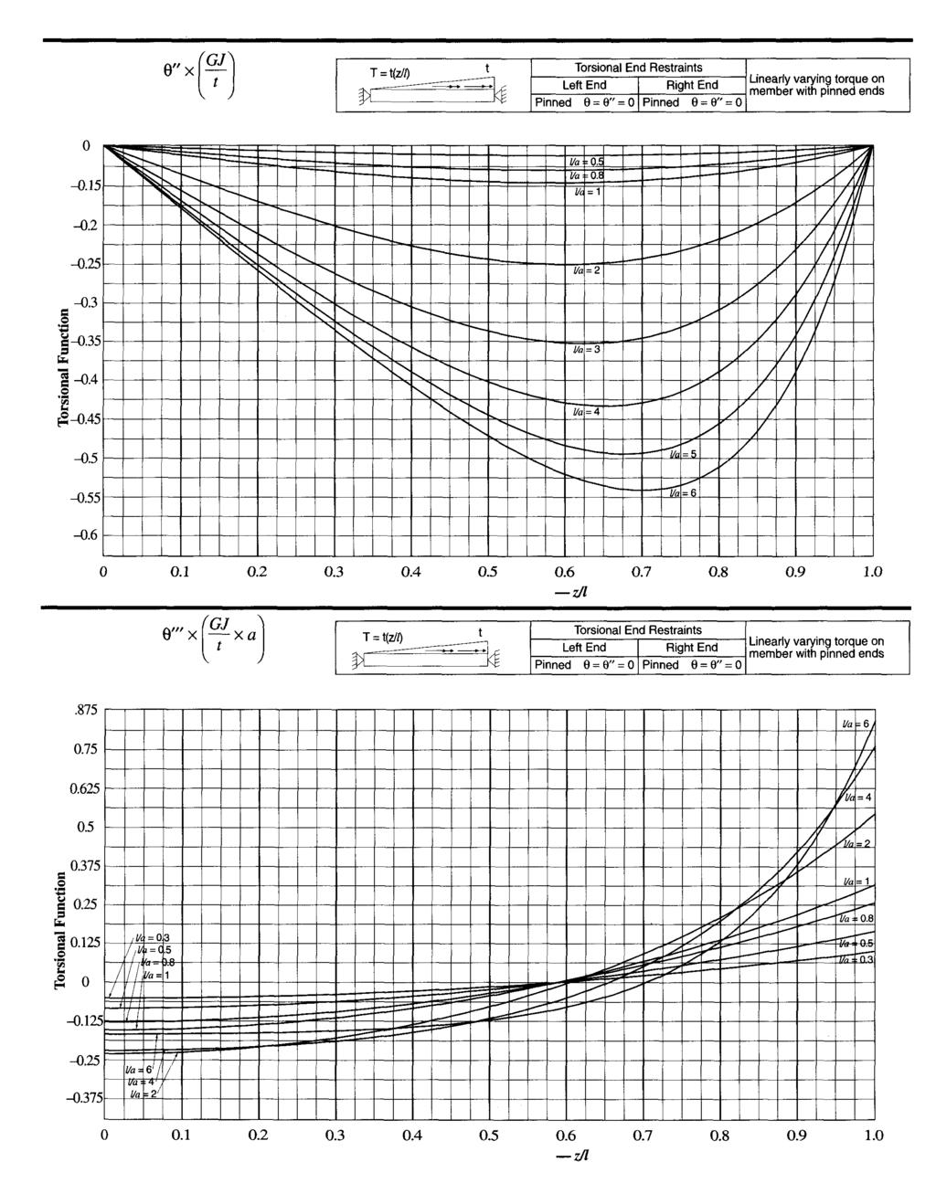
11 where, as illustrated in Figure 3.2: (3.28) (3.29) (3.30) (3.31) (3.32) For single-angles and structural tees, J may be calculated using Equation 3.4, excluding fillets. For more accurate equations including fillets, see El Darwish and Johnston (1965). Since pure torsional shear stresses will generally dominate over warping stresses, stresses due to warping are usually neglected in single angles (see Section 4.2) and structural tees (see Section 4.3); equations for other torsional properties have not been included. Since the centerlines of each element of the cross-section intersect at the shear center, the general solution of Appendix C3.1 would yield 0. A value of a (and therefore is required, however, to determine the angle of rotation using the charts of Appendix B. (3.33) (3.36) 3.3 Torsional Functions In addition to the torsional properties given in Section 3.2 above, the torsional rotation 0 and its derivatives are necessary for the solution of equations 3.1, 3.2, and 3.3. In Appendix B, these equations have been evaluated for twelve common combinations of end condition (fixed, pinned, and free) and load type. Members are assumed to be prismatic. The idealized fixed, pinned, and free torsional end conditions, for which practical examples are illustrated in Figure 3.3, are defined in Appendix C.2. The solutions give the rotational response and derivatives along the span corresponding to different values of the ratio of the member span length l to the torsional property a of its cross-section. The functions given are non-dimensional, that is, each term is multiplied by a factor that is dependent upon the torsional properties of the member and the magnitude of the applied torsional moment. For each case, there are four graphs providing values of, and Each graph shows the value of the torsional functions (vertical scale) plotted against the fraction of the span length (horizontal scale) from the left support. Some of the curves have been plotted as a dotted line for ease of reading. The resulting equations for each of these cases are given in Appendix C.4. For single angles, the following formulas (Bleich, 1952) may be used to determine C w : (3.34) where and are the centerline leg dimensions (overall leg dimension minus half the angle thickness t for each leg). For structural tees: where (3.35) Figure 3.2, Figure
12 Chapter 4 ANALYSIS FOR TORSION In this chapter, the determination of torsional stresses and their combination with stresses due to bending and axial load is covered for both open and closed cross-sections. The AISC Specification provisions for the design of members subjected to torsion and serviceability considerations for torsional rotation are discussed. 4.1 Torsional Stresses on I-, C-, and Z-shaped Open Cross-Sections Shapes of open cross-section tend to warp under torsional loading. If this warping is unrestrained, only pure torsional stresses are present. However, when warping is restrained, additional direct shear stresses as well as longitudinal stresses due to warping must also be considered. Pure torsional shear stresses, shear stresses due to warping, and normal stresses due to warping are each related to the derivatives of the rotational function Thus, when the derivatives of are determined along the girder length, the corresponding stress conditions can be evaluated. The calculation of these stresses is described in the following sections Shear Stresses Due to Warping When a member is allowed to warp freely, these shear stresses will not develop. When warping is restrained, these are inplane shear stresses that are constant across the thickness of an element of the cross-section, but vary in magnitude along the length of the element. They act in a direction parallel to the edge of the element. The magnitude of these stresses is determined by the equation: GENERAL ORIENTATION FIGURE Pure Torsional Shear Stresses These shear stresses are always present on the cross-section of a member subjected to a torsional moment and provide the resisting moment as described in Section 2.2. These are in-plane shear stresses that vary linearly across the thickness of an element of the cross-section and act in a direction parallel to the edge of the element. They are maximum and equal, but of opposite direction, at the two edges. The maximum stress is determined by the equation: where (4.1) pure torsional shear stress at element edge, ksi shear modulus of elasticity of steel, 11,200 ksi thickness of element, in. rate of change of angle of rotation first derivative of with respect to z (measured along longitudinal axis of member) The pure torsional shear stresses will be largest in the thickest elements of the cross-section. These stress states are illustrated in Figures 4. 1b, 4.2b, and 4.3b for I-shapes, channels, and Z-shapes. Figure
13 where (4-2a) shear stress at point s due to warping, ksi modulus of elasticity of steel, 29,000 ksi warping statical moment at point s (see Appendix A), in. 4 thickness of element, in. third derivative of with respect to z These stress states are illustrated in Figures 4.1c, 4.2c, and 4.3c for I-shapes, channels, and Z-shapes. Numerical subscripts are added to represent points of the cross-section as illustrated Normal Stresses Due to Warping When a member is allowed to warp freely, these normal stresses will not develop. When warping is restrained, these are direct stresses (tensile and compressive) resulting from bending of the element due to torsion. They act perpendicular to the surface of the cross-section and are constant across the thickness of an element of the cross-section but vary in magnitude along the length of the element. The magnitude of these stresses is determined by the equation: where normal stress at point s due to warping, ksi modulus of elasticity of steel, 29,000 ksi normalized warping function at point s (see Appendix A), in. 2 second derivative of with respect to z These stress states are illustrated in Figures 4.1d, 4.2d, and 4.3d for I-shapes, channels, and Z-shapes. Numerical subscripts are added to represent points of the cross-section as illustrated Approximate Shear and Normal Stresses Due to Warping on I-Shapes (4.3a) The shear and normal stresses due to warping may be approximated for short-span I-shapes by resolving the torsional moment T into an equivalent force couple acting at the flanges as illustrated in Figure 4.4. Each flange is then analyzed as a beam subjected to this force. The shear stress at the center of the flange is approximated as: (4.2b) where is the value of the shear in the flange at any point along the length. The normal stress at the tips of the flange is approximated as: where (4.3b) bending moment on the flange at any point along the length. 4.2 Torsional Stress on Single-Angles Single-angles tend to warp under torsional loading. If this warping is unrestrained, only pure torsional shear stresses develop. However, when warping is restrained, additional direct shear stresses as well as longitudinal stress due to warping are present. Pure torsional shear stress may be calculated using Equation 4.1. Gjelsvik (1981) identified that the shear stresses due to warping are of two kinds: in-plane shear stresses, which vary from zero at the toe to a maximum at the heel of the angle; and secondary shear stresses, which vary from zero at the heel to a maximum at the toe of the angle. These stresses are illustrated in Figure 4.5. Warping strengths of single-angles are, in general, relatively small. Using typical angle dimensions, it can be shown that the two shear stresses due to warping are of approximately the same order of magnitude, but represent less than 20 percent of the pure torsional shear stress (AISC, 1993b). When all the shear stresses are added, the result is a maximum surface shear stress near mid-length of the angle leg. Since this is a local maximum that does not extend through the thickness of the angle, it is sufficient to ignore the shear stresses due to warping. Similarly, normal stresses due to warping are considered to be negligible. For the design of shelf angles, refer to Tide and Krogstad (1993). 4.3 Torsional Stress on Structural Tees Structural tees tend to warp under torsional loading. If this warping is unrestrained, only pure torsional shear stresses develop. However, when warping is restrained, additional direct shear stresses as well as longitudinal or normal stress due to warping are present. Pure torsional shear stress may be calculated using Equation 4.1. Warping stresses of structural tees are, in general, relatively small. Using typical tee dimensions, it can be shown that the shear and normal stresses due to warping are negligible. 4.4 Torsional Stress on Closed and Solid Cross-Sections Torsion on a circular shape (hollow or solid) is resisted by shear stresses in the cross-section that vary directly with distance from the centroid. The cross-section remains plane as it twists (without warping) and torsional loading develops pure torsional stresses only. While non-circular closed cross- 12
14 Table 4.1 Shear Stress Due to St. Venant's Torsion Solid Cross-Sections Closed Cross-Sections where (4.4) area enclosed by shape, measured to centerline of thickness of bounding elements as illustrated in Figure 4.7, in. 2 thickness of bounding element, in. For solid round and flat bars, square, rectangular and round HSS and steel pipe, the torsional shear stress may be calculated using the equations given in Table 4.1. Note that the equation for the hollow circular cross-section in Table 4.1 is not in a form based upon Equation 4.4 and is valid for any wall thickness. 4.5 Elastic Stresses Due to Bending and Axial Load In addition to the torsional stresses, bending and shear stresses and respectively) due to plane bending are normally present in the structural member. These stresses are determined by the following equations: (4.5) where (4.6) normal stress due to bending about either the x or y axis, ksi bending moment about either the x or y axis, kip-in. elastic section modulus, in. 3 shear stress due to applied shear in either x or y direction, ksi shear in either x or y direction, kips for the maximum shear stress in the flange for the maximum shear stress in the web. moment of inertia or in. 4 thickness of element, in. sections tend to warp under torsional loading, this warping is minimized since longitudinal shear prevents relative displacement of adjacent plate elements as illustrated in Figure 4.6. The analysis and design of thin-walled closed cross-sections for torsion is simplified with the assumption that the torque is absorbed by shear forces that are uniformly distributed over the thickness of the element (Siev, 1966). The general torsional response can be determined from Equation 3.1 with the warping term neglected. For a constant torsional moment T the shear stress may be calculated as: The value of computed using from Appendix A is the theoretical value at the center of the flange. It is within the accuracy of the method presented herein to combine this theoretical value with the torsional shearing stress calculated for the point at the intersection of the web and flange centerlines. Figure 4.8 illustrates the distribution of these stresses, shown for the case of a moment causing bending about the major axis of the cross-section and shear acting along the minor axis of the cross-section. The stress distribution in the Z-shape is somewhat complicated because the major axis is not parallel to the flanges. Axial stress may also be present due to an axial load P. 13
15 This stress may be tensile or compressive and is determined by the following equation: where normal stress due to axial load, ksi axial load, kips area, in Combining Torsional Stresses With Other Stresses Open Cross-Sections To determine the total stress condition, the stresses due to torsion are combined algebraically with all other stresses using the principles of superposition. The total normal stress is: and the total shear stress f v, is: (4.7) (4.8a) (4.9a) As previously mentioned, the terms and may be taken as zero in the following cases: 1. members for which warping is unrestrained 2. single-angle members 3. structural tee members In the foregoing, it is imperative that the direction of the stresses be carefully observed. The positive direction of the torsional stresses as used in the sign convention presented herein is indicated in Figures 4.1, 4.2, and 4.3. In the sketches accompanying each figure, the stresses are shown acting on a cross-section of the member located at distance z from the left support and viewed in the direction indicated in Figure 4.1. In all of the sketches, the applied torsional moment acts at some arbitrary point along the member in the direction indicated. In the sketches of Figure 4.8, the moment acts about the major axis of the cross-section and causes compression in the top flange. The applied shear is assumed to act vertically downward along the minor axis of the cross-section. For I-shapes, and are both at their maximum values at the edges of the flanges as shown in Figures 4.1 and 4.8. Likewise, there are always two flange tips where these stresses add regardless of the directions of the applied torsional moment and bending moment. Also for I-shapes, the maximum values of and in the flanges will always add at some point regardless of the directions of the applied torsional moment and vertical shear to give the maximum Figure 4.2. Figure
 (4.")
16 shear stress in the flange. For the web, the maximum value of adds to the value of in the web, regardless of the direction of loading, to give the maximum shear stress in the web. Thus, for I-shapes, Equations 4.8a and 4.9a may be simplified as follows: (4.8b) (4.9b) For channels and Z-shapes, generalized rules cannot be given for the determination of the magnitude of the maximum combined stress. For shapes such as these, it is necessary to consider the directions of the applied loading and to check the combined stresses at several locations in both the flange and the web. Determining the maximum values of the combined stresses for all types of shapes is somewhat cumbersome because the stresses and are not all at their maximum values at the same transverse cross-section along the length of the member. Therefore, in many cases, the stresses should be checked at several locations along the member Closed Cross-Sections For closed cross-sections, stresses due to warping are either not induced 3 or negligible. Torsional loading does, however, cause shear stress, and the total shear stress is: In the above equation, where A v = total web area for square and rectangular HSS and half the cross-sectional area for round HSS and steel pipe. 4.7 Specification Provisions Load and Resistance Factor Design (LRFD) In the following, the subscript u denotes factored loads. LRFD Specification Section H2 provides general criteria for members subjected to torsion and torsion combined with other forces. Second-order amplification (P-delta) effects, if any, are presumed to already be included in the elastic analysis from which the calculated stresses and were determined. For the limit state of yielding under normal stress: For the limit state of yielding under shear stress: For the limit state of buckling: or as appropriate. In the above equations, (4.10) (4.11) (4.12) (4.13) (4.14) (4.15) = yield strength of steel, ksi = critical buckling stress in either compression (LRFD (a) shear stresses due to pure torsion (b) in-plane shear stresses due to warping (c) secondary shear stresses due to warping Figure 4.4. Figure For a circular shape or for a non-circular shape for which warping is unrestrained, warping does not occur, i.e., and are equal to zero. 15
17 Specification Chapter E) or shear (LRFD Specification Section F2), ksi When it is unclear whether the dominant limit state is yielding, buckling, or stability, in a member subjected to combined forces, the above provisions may be too simplistic. Therefore, the following interaction equations may be useful to conservatively combine the above checks of normal stress for the limit states of yielding (Equation 4.12) and buckling (Equation 4.14). When second order effects, if any, are considered in the determination of the normal stresses: (4.16a) If second order effects occur but are not considered in determining the normal stresses, the following equation must be used: (4.16b) In the above equations, compressive critical stress for flexural or flexural-torsional member buckling from LRFD Specification Chapter E term), ksi; critical flexural stress controlled by yielding, lateral-torsional buckling (LTB), web local buckling (WLB), or flange local buckling (FLB) from LRFD Specification Chapter F term) factored axial force in the member (kips) elastic (Euler) buckling load. Shear stresses due to combined torsion and flexure may be checked for the limit state of yielding as in Equation Note that a shear buckling limit state for torsion (Equation 4.15) has not yet been defined. For single-angle members, see AISC (1993b). A more advanced analysis and/or special design precautions are suggested for slender open cross-sections subjected to torsion Allowable Stress Design (ASD) Although not explicitly covered in the ASD Specification, the design for the combination of torsional and other stresses in ASD can proceed essentially similarly to that in LRFD, except that service loads are used in place of factored loads. In the absence of allowable stress provisions for the design of members subjected to torsion and torsion combined with other forces, the following provisions, which parallel the LRFD Specification provisions above, are recommended. Second-order amplification (P-delta) effects, if any, are presumed to already be included in the elastic analysis from which the calculated stresses were determined. For the limit state of yielding under normal stress: (4.17) For the limit state of yielding under shear stress: (4.18) Figure 4.6. Figure
18 For the limit state of buckling: or as appropriate. In the above equations, (4.19) (4.20) yield strength of steel, ksi allowable buckling stress in compression (ASD Specification Chapter E), ksi allowable bending stress (ASD Specification Chapter F), ksi allowable buckling stress in shear (ASD Specification Section F4), ksi When it is unclear whether the dominant limit state is yielding, buckling, or stability, in a member subjected to combined forces, the above provisions may be too simplistic. Therefore, the following interaction equations may be useful to conservatively combine the above checks of normal stress for the limit states of yielding (Equation 4.17) and buckling (Equation 4.19). When second order effects, if any, are considered in determining the normal stresses: (4.2 la) For single-angle members, see AISC (1989b). A more advanced analysis and/or special design precautions are suggested for slender open cross-sections subjected to torsion Effect of Lateral Restraint at Load Point Chu and Johnson (1974) showed that for an unbraced beam subjected to both flexure and torsion, the stress due to warping is magnified for a W-shape as its lateral-torsional buckling strength is approached; this is analogous to beam-column behavior. Thus, if lateral displacement or twist is not restrained at the load point, the secondary effects of lateral bending and warping restraint stresses may become significant and the following additional requirement is also conservatively suggested. For the LRFD Specification provisions of Section 4.7.1, amplify the minor-axis bending stress and the warping normal stress by the factor (4.22) where is the elastic LTB stress (ksi), which can be derived for W-shapes from LRFD Specification Equation Fl-13. For the ASD Specification provisions of Section 4.7.2, amplify the minor-axis bending stress and the warping normal stress by the factor If second order effects occur but are not considered in determining the normal stresses, the following equation must be used: (4.21b) In the above equations, allowable axial stress (ASD Specification Chapter E),ksi allowable bending stress controlled by yielding, lateral-torsional buckling (LTB), web local buckling (WLB), or flange local buckling (FLB) from ASD Specification Chapter F, ksi axial stress in the member, ksi elastic (Euler) stress divided by factor of safety (see ASD Specification Section H1). Shear stresses due to combined torsion and flexure may be checked for the limit state of yielding as in Equation As with LRFD Specification provisions, a shear buckling limit state for torsion has not yet been defined. Figure
19 (4.23) where is the elastic LTB stress (ksi), given for W-shapes, by the larger of ASD Specification Equations F1-7 and F Torsional Serviceability Criteria In addition to the strength provisions of Section 4.7, members subjected to torsion must be checked for torsional rotation The appropriate serviceability limitation varies; the rotation limit for a member supporting an exterior masonry wall may differ from that for a member supporting a curtain-wall system. Therefore, the rotation limit must be selected based upon the requirements of the intended application. Whether the design check was determined with factored loads and LRFD Specification provisions, or service loads and ASD Specification provisions, the serviceability check of should be made at service load levels (i.e., against Unfactored torsional moment).the design aids of Appendix B as well as the general equations in Appendix C are required for the determination of 18
20 Chapter 5 DESIGN EXAMPLES Example 5.1 As illustrated in Figure 5.1a, a W10x49 spans 15 ft (180 in.) and supports a 15-kip factored load (10-kip service load) at midspan that acts at a 6 in. eccentricity with respect to the shear center. Determine the stresses on the cross-section and the torsional rotation. Given: The end conditions are assumed to be flexurally and torsionally pinned. The eccentric load can be resolved into a torsional moment and a load applied through the shear center as shown in Figure 5.lb. The resulting flexural and torsional loadings are illustrated in Figure 5.1c. The torsional properties are as follows: (4.5) = 12.4 ksi (compression at top; tension at bottom) (4.6) (4.6) The flexural properties are as follows: For this loading, stresses are constant from the support to the load point. Solution: Calculate Bending Stresses Figure
21 Calculate Torsional Stresses The following functions are taken from Appendix B, Case 3, with 0.5: The shear stress due to warping is: At midspan, (4.2a) At midspan 0.5) At the support, The normal stress due to warping is: At midspan, (4.3a) At the support, since Calculate Combined Stress Summarizing stresses due to flexure and torsion: In the above calculations (note that the applied torque is negative with the sign convention used in this book): The shear stress due to pure torsion is: (4.1) At midspan, since At the support, for the web, Thus, as illustrated in Figure 5.2, it can be seen that the maximum normal stress occurs at midspan in the flange at the left side tips of the flanges when viewed toward the left support and the maximum shear stress occurs at the support in the middle of the flange. Calculate Maximum Rotation The maximum rotation occurs at midspan. The service-load torque is: and for the flange, 20
22 Calculate Combined Stress (4.10) and the maximum rotation is: Calculate Maximum Rotation From Example 5.1, Example 5.2 Repeat Example 5.1 for a Compare the magnitudes of the resulting stresses and rotation with those determined in Example 5.1. Given: Solution: Calculate Bending Stresses From Example 5.1, Comparing the magnitudes of the maximum stresses and rotation for this HSS with those for the W-shape of Example 5.1: (4.5) (4.11) (4.4) Figure

23 = 9,910kip-in./rad. Determine Torsional Stiffness of Beam From Example 5.1, Thus, stresses and rotation are significantly reduced in comparable closed sections when torsion is a major factor. Example 5.3 Repeat Example 5.1 assuming the concentrated force is introduced by a W6x9 column framed rigidly to the W10x49 beam as illustrated in Figure 5.3. Assume the column is 12 ft long with its top a pinned end and a floor diaphragm provides lateral restraint at the load point. Compare the magnitudes of the resulting stresses and rotation with those determined in Examples 5.1 and 5.2. Given: For the W10X49 beam: Determine Distribution of Moment For the W6x9 column: Solution: In this example, the torsional restraint provided by the rigid connection joining the beam and column will be utilized. Determine Flexural Stiffness of Column Thus, the torsional moment on the beam has been reduced from 90 kip-in. to 8.1 kip-in. The column must be designed for an axial load of 15 kips plus an end-moment of 81.9 kip-in. The beam must be designed for the torsional moment of 8.1 kip-in., the 15-kip force from the column axial load, and a lateral force P uy due to the horizontal reaction at the bottom of the column, where Calculate Bending Stresses From Example 5.1, In the weak axis, Figure
 Comments Comparing the magnitudes of the stresses and rotation for this case with that of Example 5.1: W10x49 unrestrained 40.4 ksi 11.4 ksi 0.062 rad. W10x49 restrained 16.3 ksi 3.00 ksi 0.")
24 that used in Example 5.1, the maximum rotation, which occurs at midspan, is also reduced to 9 percent of that calculated in Example 5.1 or: (4.5) Comments Comparing the magnitudes of the stresses and rotation for this case with that of Example 5.1: W10x49 unrestrained 40.4 ksi 11.4 ksi rad. W10x49 restrained 16.3 ksi 3.00 ksi rad. (4.2b) Calculate Torsional Stress Since the torsional moment has been reduced to 9 percent of that used in Example 5.1, the torsional stresses are also reduced to 9 percent of those calculated in Example 5.1. These stresses are summarized below. Calculate Combined Stress Summarizing stresses due to flexure and torsion As before, the maximum normal stress occurs at midspan in the flange. In this case, however, the maximum shear stress occurs at the support in the web. Calculate Maximum Rotation Since the torsional moment has been reduced to 9 percent of Figure
25 Thus, consideration of available torsional restraint significantly reduces the torsional stresses and rotation. Example 5.4 The welded plate-girder shown in Figure 5.4a spans 25 ft (300 in.) and supports 310-kip and 420-kip factored loads (210-kip and 285-kip service loads). As illustrated in Figure 5.4b, these concentrated loads are acting at a 3-in. eccentricity with respect to the shear center. Determine the stresses on the cross-section and the torsional rotation. (3.5) (3.6) Given: The end conditions are assumed to be flexurally and torsionally pinned. Solution: Calculate Cross-Sectional Properties (3.7) (3.8) (3.9) (3.10) Calculate Torsional Properties (3.4) (3.11) Calculate Bending Stresses By inspection, points D and E are most critical. At point D: (4.5) At point = 26.6 ksi (compression at top; tension at bottom) 24
26 Between points D and E: (4.6) (4.6) At point E For this loading, shear stresses are constant from point D to point E. Calculate Torsional Stresses The shear stress due to pure torsion is calculated as: (4.1) The effect of each torque at points D and E will be determined individually and then combined by superposition. Use Case 3 with 0.3 (The effects of each load are added by superposition). and the stresses are as follows: The shear stress due to warping is calculated as: (4.2a) At point D, At point E, The normal stress due to warping is calculated as: (4.3a) 25
27 At point D, from the left end of the beam (point A). At this location, The service-load torques are: Calculate Combined Stress Summarizing stresses due to flexure and torsion: The maximum rotation is: Thus, it can be seen that the maximum normal stress occurs at point D in the flange and the maximum shear stress occurs at point E (the support) in the web. Calculate Maximum Rotation From Appendix B, Case 3 with a = 0.3, it is estimated that the maximum rotation will occur at approximately 14½ feet Example 5.5 The MCl8x42.7 channel illustrated in Figure 5.5a spans 12 ft (144 in.) and supports a uniformly distributed factored load of 3.6 kips/ft (2.4 kips/ft service load) acting through the centroid of the channel. Determine the stresses on the crosssection and the torsional rotation, Given: The end conditions are assumed to be flexurally and torsionally fixed. The eccentric load can be resolved into a torsional moment and a load applied through the shear center as shown in Figure 5.5b. The resulting flexural and torsional loadings are illustrated in Figure 5.5c. The torsional properties are as follows: Figure
28 Solution: From the graphs for Case 7 in Appendix B, the extreme values of the torsional functions are located at values of 0, 0.2, 0.5, and 1.0. Thus, the stresses at the supports and and midspan are of interest. Calculate Bending Stresses At the support: (4.6) (4.6) (4.5) (4.6) Since is maximum at the support, its value at as well as the value of is not necessary. Calculate Torsional Stresses (4.6) = (3.6 kips/ft)(1.85in.) = 6.66 kip-in./ft The following functions are taken from Appendix B, Case 7: (4.5) 27
29 At midspan In the above calculations: The normal stress at point s due to warping is: The shear stress due to pure torsion is: At the support, At the support, and at midspan, since for the web, and for the flange, At midspan, The shear stress at point s due to warping is: (Refer to Figure 5.5d or Appendix A for locations of critical points s) At midspan, since At the support, 28
30 Calculate Combined Stress Summarizing stresses due to flexure and torsion: = rad. Example 5.6 As illustrated in Figure 5.6a, a 3x3x½ single angle is cantilevered 2 ft (24 in.) and supports a 2-kip factored load (1.33-kip service load) at midspan that acts as shown with a 1.5-in. eccentricity with respect to the shear center. Determine the stresses on the cross-section, the torsional rotation, and if the member is adequate if F y = 50 ksi. Given: The end condition is assumed to be flexurally and torsionally fixed. The eccentric load can be resolved into a torsional moment and a load applied through the shear center as shown in Figure 5.6b. The resulting flexural and torsional loadings are illustrated in Figure 5.6c. The flexural and torsional properties are as follows: Solution: Check Flexure Since the stresses due to warping of single-angle members are negligible, the flexural design strength will be checked according to the provisions of the AISC Specification for LRFD of Single Angle Members (AISC, 1993b). Thus, it can be seen that the maximum normal stress (tension) occurs at the support at point 2 in the the flange and the maximum shear stress occurs at at point 3 in the web. Calculate Maximum Rotation The maximum rotation occurs at midspan. The service-load distributed torque is: and the maximum rotation is: Figure
31 With the tip of the vertical angle leg in compression, local buckling and lateral torsional buckling must be checked. The following checks are made for bending about the geometric axes (Section 5.2.2). For local buckling (Section 5.1.1), Check Shear Due to Flexure and Torsion The shear stress due to flexure is, The total shear stress is, From LRFD Single-Angle Specification Section 3, Calculate Maximum Rotation The maximum rotation will occur at the free end of the cantilever. The service-load torque is: Example 5.7 The crane girder and loading illustrated in Figure 5.7 is taken from Example 18.1 of the AISC Design Guide Industrial 30
32 Buildings: Roofs to Column Anchorage (Fisher, 1993). Use the approximate approach of Section to calculate the maximum normal stress on the combined section. Determine if the member is adequate if F y = 36 ksi. Given: For the strong-axis direction: Calculate Normal Stress due to Warping From Section 4.1.4, the normal stress due to warping may be approximated as: (4.3b) Note that the subscripts 1 and 2 indicate that the section modulus is calculated relative to the bottom and top, respectively, of the combined shape. For the channel/top flange assembly: Note that the subscript t indicates that the section modulus is calculated based upon the properties of the channel and top flange area only. Solution: 38.9 kip-ft (weak-axis bending moment on top flange assembly) 50.3 in. 3 Calculate Normal Stress Due to Strong-Axis Bending Calculate Total Normal Stress (4.8a) (4.5) Comments Since it is common practice in crane-girder design to assume that the lateral loads are resisted only by the top flange assembly, the approximate solution of Section is extremely useful for this case. (4.5) 31
33 Appendix A TORSIONAL PROPERTIES W-, M-, S-, and HP-Shapes Torsional Properties Statical Moments Shape 33
34 W-, M-, S-, and HP-Shapes Torsional Properties Statical Moments Shape 34
35 W-, M-, S-, and HP-Shapes Torsional Properties Statical Moments Shape 35
36 W-, M-, S-, and HP-Shapes Torsional Properties Statical Moments Shape 36
37 W-, M-, S-, and HP-Shapes Torsional Properties Statical Moments Shape 37
38 W-, M-, S-, and HP-Shapes Torsional Properties Statical Moments Shape 38
39 W-, M-, S-, and HP-Shapes Torsional Properties Statical Moments Shape 39
40 W-, M-, S-, and HP-Shapes Torsional Properties Statical Moments Shape 40
41 W-, M-, S-, and HP-Shapes Torsional Properties Statical Moments Shape 41
42 C- and MC-Shapes Torsional Properties Statical Moments Shape 42
43 C- and MC-Shapes Torsional Properties Statical Moments Shape 43
44 WT-, MT-, and ST-Shapes Torsional Properties WT-, MT-, and ST-Shapes Torsional Properties Shape Shape 44
45 WT-, MT-, and ST-Shapes Torsional Properties WT-, MT-, and ST-Shapes Torsional Properties Shape Shape 45
46 WT-, MT-, and ST-Shapes Torsional Properties WT-, MT-, and ST-Shapes Torsional Properties Shape Shape 46
47 WT-, MT-, and ST-Shapes Torsional Properties Shape 47
48 Single Angles Torsional Properties Single Angles Torsional Properties Shape Shape 48
49 Single Angles Torsional Properties Shape 49
50 Square HSS Square HSS Rectangular HSS Shape Shape Shape 50
51 Rectangular HSS Rectangular HSS Rectangular HSS Shape Shape Shape 51
52 Rectangular HSS Steel Pipe Shape Nominal Diameter 52
53 Z-shapes Torsional Properties Statical Moments Shape 53
54 Appendix B CASE CHARTS OF TORSIONAL FUNCTIONS Determine the case based upon the end conditions and type of loading. For the given cross-section and span length, compute the value of using in inches and a as given in Appendix A. With this value, enter the appropriate chart from the loading. At the desired location along the horizontal scale, read vertically upward to the appropriate curve and read from the vertical scale the value of the torsional function. (For values of between curves, use linear interpolation.) This value should then be divided by the factor indicated by the group of terms shown in the labels on the curves to obtain the value of This result may then be used in Equation 4.1, 4.2, or 4.3 to determine Sign Convention In all cases, the torsional moment is shown acting in a counter-clockwise direction when viewed toward the left end of the member. This is considered to be a positive moment in this book. Thus, if the applied torsional moment is in the opposite direction, it should be assigned a negative value for computational purposes. A positive stress or rotation computed with the equations and torsional constants of this book acts in the direction shown in the cross-sectional views shown in Figures 4.1, 4.2, and 4.3. A negative value indicates the direction is opposite to that shown. On some of the Case Charts, the applied torsional moment is indicated by a vector notation using a line with two arrowheads. This notation indicates the "right-hand rule," wherein the thumb of the right hand is extended and pointed in the direction of the vector, and the remaining fingers of the right hand curve in the direction of the moment. In Figures 4.2 and 4.3, the positive direction of the stresses is shown for channels and Z-shapes oriented such that the top flange extended to the left when viewed toward the left end of the member. For the reverse orientation of these members with the applied torque remaining in a counterclockwise direction, the following applies: the positive direction of the stresses in the flanges is the same as shown in Figures 4.2b and 4.3b. For example, at the top edge of the top flange, a positive stress acts from left to right. A positive stress at the left edge of the web acts downward; a positive stress at the right edge of the web acts upward. the positive direction of the stresses at the corresponding points on the reversed section are opposite those shown in Figures 4.2d and 4.3d. For example, a positive stress at the tips of the flanges, point o, is a tensile stress. 54
55 Case 1 Case 1 55
56 Case 2 Case 2 56
57 Case 2 Case 2 57

58 Case 3 Rev. 3/1/03 Case 3 Rev. 3/1/03 58

59 Case 3 Rev. 3/1/03 Case 3 Rev. 3/1/03 59

60 Case 3 Rev. 3/1/03 Case 3 60

61 Case 3 Case 3 61
62 Case 3 Case 3 62

63 Case 3 Case 3 63

64 Case 4 Case 4 64

65 Case 4 Case 4 65

66 Case 5 Case 5 66
67 Case 5 Case 5
68 Case 6 Case 6 68
69 Case 6 Case 6 69
70 Case 6 Case 6 70
71 Case 6 Case 6 71

72 Case 6 Case 6 72
73 Case 6 Case 6 73
74 Case 7 Case 7 74
75 Case 7 Case 7 75

76 Case 8 Case 8 76
77 Case 8 Case 8 77
78 Case 9 Case 9 78
79 Case 9 Case 9 79
80 Case 9 Case 9 80
81 Case 9 Case 9 81
82 Case 9 Case 9 82
83 Case 9 Case 9 83
84 Case 9 Case 9 84
85 Case 9 Case 9 85
86 Case 9 Case 9 86
87 Case 9 Case 9 87
88 Case 9 Case 9 88

89 Case 9 Case 9 89
90 Case 10 Case 10 90
91 Case 10 Case 10 91
92 Case 10 Case 10 92
93 Case 10 Case 10 93
94 Case 10 Case 10 94
95 Case 10 Case 10
96 Case 10 Case 10 96
97 Case 10 Case 10 97
98 Case 10 Case 10 98
99 Case 10 Case 10 99
100 Case 10 Case 10
101 Case 10 Case

102 Case 11 Case
103 Case 11 Case
104 Case 12 Case
105 Case 12 Case
106 Appendix C SUPPORTING INFORMATION C.1 General Equations for and its Derivatives Following are general equations for for a constant torsional moment, uniformly distributed torsional moment, and linearly varying torsional moment. They are developed from Equation 2.4 in Section 2.2. C.1.1 Constant Torsional Moment For a constant torsional moment T along a portion of the member as illustrated in Figure C.1a, the following equation may be developed: or (C.6) (C.7) Differentiating Equation 2.4 and substituting the above yields: (C.8) which may be solved as: where z = distance along Z-axis from left support, in. A, B, C = constants that are determined from boundary conditions C. 1.2 Uniformly Distributed Torsional Moment A member subjected to a uniformly distributed torsional moment t is illustrated in Figure C.lb. For this case, examine a small segment of the member of length dz. By summation of torsional moments: (C.9) C.2. Boundary Conditions The general equations contain constants that are evaluated for specific cases by imposing the appropriate boundary conditions. These conditions specify mathematically the physical restraints at the ends of the member. They are summarized as follows: (C.2) or (C.3) Differentiating Equation 2.4 and substituting the above yields: (C.4) which may be solved as: (C.5) C.I.3 Linearly Varying Torsional Moment For a member subjected to a linearly varying torsional moment as illustrated in Figure C.lc, again examine a small element of the member length dz. Summing the torsional moments: Figure C.I. 107
107 Physical Condition No rotation Torsional End Condition Fixed or Pinned Mathematical Condition C.3.1 General Solution Referring to the general cross-section and notation in Figure C.3, the torsional properties may be expressed as follows: Cross-section cannot warp Fixed end (C.13) Cross-section can warp freely Pinned or Free (C.14) Additionally, the following conditions must be satisfied at a support over which the member is continuous or at a point of applied torsional moment: (C.10) (C.11) where (C.15) (C.16) (C.12) In all solutions in Appendix C, ideal end conditions have been assumed, i.e., free, fixed, or pinned. Where these conditions do not apply, a more advanced analysis may be necessary. A torsionally fixed end (full warping restraint) is more difficult to achieve than a flexurally fixed end. If the span is one of several for a continuous beam, with each span similarly loaded, there is inherent fixity for flexure and flange warping. If however, the beam is an isolated span, Ojalvo (1975) demonstrated that a closed box made up of several plates or a channel, as illustrated in Figure C.2, would approximate a torsionally fixed end. Simply welding to an end-plate or column flange may not provide sufficient restraint. C.3.2 Torsional Constant J for Open Cross-Sections (C.17) (C.18) The following equations for J provide a more accurate value than the simple approximation given previously. For I-shapes with parallel-sided flanges as illustrated in Figure C.4a: C.3. Evaluation of Torsional Properties Following are the general solutions for the torsional properties given in Chapter 3 and more accurate equations for the torsional constant J for I-shapes, channels, and Z-shapes. Figure C.2. Figure C
108 (C.19) where (C.29) (C.20) For flange slopes other than percent, the value of may be found by linear interpolation between as given above and as given below for parallel-sided flanges: For I-shapes with sloping-sided flanges as illustrated in Figure C.4b: where for I-shapes with flange slopes of (C.21) (C.22) percent only: (C.23) For flange slopes other than percent, the value of may be found by linear interpolation between and as given above for parallel-sided flanges: (C.30) (C.31) (C.32) (C.33) (C.34) For Z-shapes with parallel-sided flanges as illustrated in Figure C.4d: (C.35) (C.24) (C.25) (C.26) (C.27) For channels as illustrated in Figure C.4c: where for channels with flange slopes of (C.28) percent only: Figure C
109 where (C.37) (C.36) C.4 Solutions to Differential Equations for Cases in Appendix B Following are the solutions of the differential equations using the proper boundary conditions. Take derivatives of to find 110
110 where: where: 111
111 where: 112
112 REFERENCES AASHTO, 1993, Guide Specifications for Horizontally Curved Highway Bridges, AASHTO, Washington, D.C. AISC, 1994, LRFD Manual of Steel Construction, 2nd Ed., AISC, Chicago, IL. AISC, 1993a, Load and Resistance Factor Design Specification for Structural Steel Buildings, AISC, Chicago, IL. AISC, 1993b, Specification for Load and Resistance Factor Design of Single-Angle Members, AISC, Chicago, IL. AISC, 1989a, Specification for Structural Steel Buildings, Allowable Stress Design, AISC, Chicago, IL. AISC, 1989b, Specification for Allowable Stress Design of Single-Angle Members, AISC, Chicago, IL. AISC, 1986, "Horizontally Curved Girders," Highway Structures Design Handbook, Volume II, Chapter 6, AISC, Chicago, IL. Bleich, F, 1952, Buckling Strength of Metal Structures, McGraw-Hill, Inc., New York, NY. Boothby, T. E., 1984, "The Application of Flexural Methods to Torsional Analysis of Thin-Walled Open Sections," Engineering Journal, Vol. 21, No. 4, (4th Qtr.), pp , AISC, Chicago, IL. Chu, K. H. and Johnson, R. B., 1974, "Torsion in Beams with Open Sections," Journal of the Structural Division, Vol. 100, No. ST7 (July), p. 1397, ASCE, New York, NY. El Darwish, I. A. and Johnston, B. G., 1965, "Torsion of Structural Shapes," Journal of the Structural Division, Vol. 91, No. ST1 (Feb.), ASCE, New York, NY. Evick, D. R. and Heins, C. P., 1972, "Torsion of Nonprismatic Beams of Open Section," Journal of the Structural Division, Vol. 98, No. ST12 (Dec.), ASCE, New York, NY. Galambos, T. V, 1988, Guide to Stability Design Criteria for Metal Structures, 4th Ed., John Wiley & Sons, Inc., New York, NY. Gjelsvik, A., 1981, The Theory of Thin-Walled Bars, John Wiley & Sons, New York, NY. Heins, C. R, 1975, Bending and Torsional Design in Structural Members, Lexington Book Co., Lexington, MA. Heins, C. P. and Firmage, D. A., 1979, Design of Modern Steel Highway Bridges, John Wiley Interscience, New York, NY. Heins, C. P. and Kuo, J. T., 1972, "Composite Beams in Torsion," Journal of the Structural Division, Vol. 98, No. ST5 (May), ASCE, New York, NY. Heins, C. P. and Potocko, R. A., 1979, "Torsional Stiffness of I-Girder Webs," Journal of the Structural Division, Vol. 105, No. ST8 (Aug.), ASCE, New York, NY. Heins, C. P. and Seaburg, P. A., 1963, Torsion Analysis of Rolled Steel Sections, Bethlehem Steel Company, Bethlehem, PA. Hotchkiss, J. G., 1966, "Torsion of Rolled Steel Sections in Building Structures," Engineering Journal, Vol. 3, No. 1, (Jan.), pp , AISC, Chicago, IL. Johnston, B. G., 1982, "Design of W-Shapes for Combined Bending and Torsion," Engineering Journal, Vol. 19, No. 2. (2nd Qtr.), pp , AISC, Chicago, IL. Johnston, B. G., Lin, F. J., and Galambos, T. V, 1980, Basic Steel Design, 2nd Ed., Prentice-Hall, Englewood Cliffs, NJ. Liew, J. Y. R., Thevendran, V, Shanmugam, N. E., and Tan, L. O., 1995, "Behaviour and Design of Horizontally Curved Steel Beams," Journal of Constructional Steel Research, Vol. 32, No. 1, pp , Elsevier Applied Science, Oxford, United Kingdom. Lin, PH., 1977, "Simplified Design for Torsional Loading of Rolled Steel Members," Engineering Journal, Vol. 14, No. 3. (3rd Qtr.), pp , AISC, Chicago, IL. Lyse, I. and Johnston, B. G., 1936, "Structural Beams in Torsion," ASCE Transactions, Vol. 101, ASCE, New York, NY. Nakai, H. and Heins, C. P., 1977, "Analysis Criteria for Curved Bridges," Journal of the Structural Division, Vol. 103, No. ST7 (July), ASCE, New York, NY. Nakai, H. and Yoo, C. H., 1988, Analysis and Design of Curved Steel Bridges, McGraw-Hill, Inc., New York, NY. Ojalvo, M., 1975, "Warping and Distortion at I-Section Joints" Discussion, Journal of the Structural Division, Vol. 101, No. ST1 (Jan.), ASCE, New York, NY. Ojalvo, M. and Chamber, R., 1977, "Effect of Warping Restraints on I-Beam Buckling," Journal of the Structural Division, Vol. 103, No. ST12 (Dec.), ASCE, New York, NY. Salmon, C. G. and Johnson, J. E., 1990, Steel Structures Design and Behavior, 3rd Ed., Harper Collins Publishers, New York, NY. Siev, A., 1966, 'Torsion in Closed Sections," Engineering Journal, Vol. 3, No. 1, (January), pp , AISC, Chicago, IL. Tide, R. H. R. and Krogstad, N. V, 1993, "Economical Design 113
113 of Shelf Angles," Proceedings of the Symposium on Masonry: Design and Construction, Problems and Repair, STP 1180, American Society for Testing and Materials, Philadelphia, PA. Timoshenko, S., 1945, "Theory of Bending, Torsion and Buckling of Thin-Walled Members of Open Cross-Section," Journal of the Franklin Institute, March/April/May, Philadelphia, PA. Tung, D. H. H. and Fountain, R. S., 1970, "Approximate Torsional Analysis of Curved Box Girders by the M/R Method," Engineering Journal, Vol. 7, No. 3, (July), pp , AISC, Chicago, EL. Vlasov, V. Z., 1961, Thin-Walled Elastic Beams, National Science Foundation, Wash., DC. Young, W. C, 1989, Roark's Formulas for Stress & Strain, McGraw-Hill, Inc., New York, NY. 114
114 NOMENCLATURE A area, in. 2 ; also, constant determined from boundary conditions (see Equations C.1, C.5, C.9, and C.14) B constant determined from boundary conditions (see Equations C.1, C.5, C.9, and C.14) C constant determined from boundary conditions (see Equations C.1, C.5, C.9, and C.14) C w warping constant of cross-section, in. 6 D 1 variable in Equation C.26, in. D 2 variable in Equation C.29, in. D 3 variable in Equation C.42, in. D 4 variable in Equation C.36, in. E modulus of elasticity of steel, 29,000 ksi E 0 horizontal distance from Centerline of channel web to shear center, in. F variable in Equation C.30, in. F a allowable axial stress (ASD), ksi F b allowable bending stress (ASD), ksi F e ' Euler stress divided by factor of safety (see ASD Specification Section H1), ksi F v allowable shear stress (ASD), ksi F y yield strength of steel, ksi F cr critical buckling stress, ksi G shear modulus of elasticity of steel, 11,200 ksi H variable in Equation 3.37 I moment of inertia, in. 4 J torsional constant of cross-section, in. 4 M bending moment, kip-in. P Q concentrated force, kips statical moment about the neutral axis of the entire cross-section of the cross-sectional area between the free edges of the cross-section and a plane cutting the cross-section across the minimum thickness at the point under examination, in. 3 Q f value of Q for a point in the flange directly above the vertical edge of the web, in. 3 Q s value of Q for a point at mid-depth of the cross-section, in. 3 R fillet radius, in. S elastic section modulus, in. 3 ; also, variable used in calculation of torsional properties (see Equation 3.31 or C.38) S ws warping statical moment at point s on cross-section, T T t T w V in. 4 applied concentrated torsional moment, kip-in. resisting moment due to pure torsion, kip-in. resisting moment due to warping torsion, kip-in. shear, kips V s variable in Equation C.32 or C.39, in. W ns normalized warping function at point s on cross-section, in. 2 a torsional constant as defined in Equation 3.6 b width of cross-sectional element, in. b' variable in Equation 3.21 or 3.30, in. b f flange width, in. dt incremental torque corresponding to incremental length dz, kip-in. dz incremental length along Z-axis, in. e eccentricity, in. e 0 horizontal distance from outside of web of channel to shear center, in. f a axial stress under service load, ksi f n total normal stress due to torsion and all other causes, ksi f v total shear stress due to torsion and all other causes, ksi h depth center-to-center of flanges for I-, C-, and Z- shaped members, in. depth minus half flange thickness for structural tee, in. leg width minus half leg thickness for single angles, in. k torsional stiffness from Equation 2.1 l span length, in. m thickness of sloping flange at beam Centerline (see Figure C.4b), in. s subscript relative to point 0, 1, 2,... on cross-section t distributed torque, kip-in, per in.; also, thickness of cross-sectional element, in. t f flange thickness, in. t w web thickness, in. t l thickness of sloping flange at toe (see Figure C.4b), in. t 2 thickness of sloping flange, ignoring fillet, at face of web (see Figure C.4b), in. u subscript denoting factored loads (LRFD); also, variable in Equation 3.22 or 3.31, in. u' variable in Equation 3.32, in. x subscript relating to strong axis y z subscript relating to weak axis distance along Z-axis of member from left support, in. angle of rotation, radians first derivative of with respect to z second derivative of with respect to z third derivative of with respect to z 115
115 fourth derivative of with respect to z distance from support to point of applied torsional moment or to end of uniformly distributed torsional load over a portion of span, divided by span length l variable in Equation C.19, in. variable in Equation C.22, in. variable in Equation C.35, in. variable in Equation C.28, in. variable in Equation C.30, in. 0.90, resistance factor for yielding (LRFD) 0.85, resistance factor for buckling (LRFD) perpendicular distance to tangent line from centroid (see Figure C.3), in. perpendicular distance to tangent line from shear center (see Figure C.3), in. normal stress due to axial load, ksi normal stress due to bending, ksi normal stress at point s due to warping torsion, ksi shear stress, ksi shear stress at element edge due to pure torsion, ksi shear stress at point s due to warping torsion, ksi 116

116 DESIGN GUIDE SERIES American Institute of Steel Construction, Inc. One East Wacker Drive, Suite 3100 Chicago, Illinois Pub. No. D809 (5M297)
TORSION INCLUDING WARPING OF OPEN SECTIONS (I, C, Z, T AND L SHAPES)
") Page1 TORSION INCLUDING WARPING OF OPEN SECTIONS (I, C, Z, T AND L SHAPES) Restrained warping for the torsion of thin-wall open sections is not included in most commonly used frame analysis programs. Almost
Page1 TORSION INCLUDING WARPING OF OPEN SECTIONS (I, C, Z, T AND L SHAPES) Restrained warping for the torsion of thin-wall open sections is not included in most commonly used frame analysis programs. Almost
MODULE C: COMPRESSION MEMBERS
 MODULE C: COMPRESSION MEMBERS This module of CIE 428 covers the following subjects Column theory Column design per AISC Effective length Torsional and flexural-torsional buckling Built-up members READING:
Failure in Flexure. Introduction to Steel Design, Tensile Steel Members Modes of Failure & Effective Areas
 Introduction to Steel Design, Tensile Steel Members Modes of Failure & Effective Areas MORGAN STATE UNIVERSITY SCHOOL OF ARCHITECTURE AND PLANNING LECTURE VIII Dr. Jason E. Charalambides Failure in Flexure!
Karbala University College of Engineering Department of Civil Eng. Lecturer: Dr. Jawad T. Abodi
 Chapter 04 Structural Steel Design According to the AISC Manual 13 th Edition Analysis and Design of Compression Members By Dr. Jawad Talib Al-Nasrawi University of Karbala Department of Civil Engineering
Karbala University College of Engineering Department of Civil Eng. Lecturer: Dr. Jawad T. Abodi
 Chapter 05 Structural Steel Design According to the AISC Manual 13 th Edition Analysis and Design of Beams By Dr. Jawad Talib Al-Nasrawi University of Karbala Department of Civil Engineering 71 Introduction
Singly Symmetric Combination Section Crane Girder Design Aids. Patrick C. Johnson
 Singly Symmetric Combination Section Crane Girder Design Aids by Patrick C. Johnson PCJohnson@psu.edu The Pennsylvania State University Department of Civil and Environmental Engineering University Park,
research report Design Example for Analytical Modeling of a Curtainwall and Considering the Effects of Bridging (All-Steel Design Approach)
") research report Design Example for Analytical Modeling of a Curtainwall and Considering the Effects of Bridging (All-Steel Design Approach) RESEARCH REPORT RP18- August 018 Committee on Specifications
research report Design Example for Analytical Modeling of a Curtainwall and Considering the Effects of Bridging (All-Steel Design Approach) RESEARCH REPORT RP18- August 018 Committee on Specifications
Accordingly, the nominal section strength [resistance] for initiation of yielding is calculated by using Equation C-C3.1.
![Accordingly, the nominal section strength [resistance] for initiation of yielding is calculated by using Equation C-C3.1.](/thumbs/89/98617066.jpg "Accordingly, the nominal section strength [resistance] for initiation of yielding is calculated by using Equation C-C3.1.") C3 Flexural Members C3.1 Bending The nominal flexural strength [moment resistance], Mn, shall be the smallest of the values calculated for the limit states of yielding, lateral-torsional buckling and distortional
C3 Flexural Members C3.1 Bending The nominal flexural strength [moment resistance], Mn, shall be the smallest of the values calculated for the limit states of yielding, lateral-torsional buckling and distortional
General Comparison between AISC LRFD and ASD
 General Comparison between AISC LRFD and ASD 1 General Comparison between AISC LRFD and ASD 2 AISC ASD and LRFD AISC ASD = American Institute of Steel Construction = Allowable Stress Design AISC Ninth
ENCE 455 Design of Steel Structures. III. Compression Members
 ENCE 455 Design of Steel Structures III. Compression Members C. C. Fu, Ph.D., P.E. Civil and Environmental Engineering Department University of Maryland Compression Members Following subjects are covered:
Compression Members. ENCE 455 Design of Steel Structures. III. Compression Members. Introduction. Compression Members (cont.)
") ENCE 455 Design of Steel Structures III. Compression Members C. C. Fu, Ph.D., P.E. Civil and Environmental Engineering Department University of Maryland Compression Members Following subjects are covered:
ENCE 455 Design of Steel Structures III. Compression Members C. C. Fu, Ph.D., P.E. Civil and Environmental Engineering Department University of Maryland Compression Members Following subjects are covered:
COURSE TITLE : APPLIED MECHANICS & STRENGTH OF MATERIALS COURSE CODE : 4017 COURSE CATEGORY : A PERIODS/WEEK : 6 PERIODS/ SEMESTER : 108 CREDITS : 5
 COURSE TITLE : APPLIED MECHANICS & STRENGTH OF MATERIALS COURSE CODE : 4017 COURSE CATEGORY : A PERIODS/WEEK : 6 PERIODS/ SEMESTER : 108 CREDITS : 5 TIME SCHEDULE MODULE TOPICS PERIODS 1 Simple stresses
: APPLIED MECHANICS & STRENGTH OF MATERIALS COURSE CODE : 4021 COURSE CATEGORY : A PERIODS/ WEEK : 5 PERIODS/ SEMESTER : 75 CREDIT : 5 TIME SCHEDULE
 COURSE TITLE : APPLIED MECHANICS & STRENGTH OF MATERIALS COURSE CODE : 4021 COURSE CATEGORY : A PERIODS/ WEEK : 5 PERIODS/ SEMESTER : 75 CREDIT : 5 TIME SCHEDULE MODULE TOPIC PERIODS 1 Simple stresses
Downloaded from Downloaded from / 1
 PURWANCHAL UNIVERSITY III SEMESTER FINAL EXAMINATION-2002 LEVEL : B. E. (Civil) SUBJECT: BEG256CI, Strength of Material Full Marks: 80 TIME: 03:00 hrs Pass marks: 32 Candidates are required to give their
UNIT- I Thin plate theory, Structural Instability:
 UNIT- I Thin plate theory, Structural Instability: Analysis of thin rectangular plates subject to bending, twisting, distributed transverse load, combined bending and in-plane loading Thin plates having
The subject of this paper is the development of a design
 The erformance and Design Checking of Chord-Angle Legs in Joist Girders THEODORE V. GALAMBOS ABSTRACT The subject of this paper is the development of a design checking method for the capacity of the outstanding
Structural Steelwork Eurocodes Development of A Trans-national Approach
 Structural Steelwork Eurocodes Development of A Trans-national Approach Course: Eurocode Module 7 : Worked Examples Lecture 0 : Simple braced frame Contents: 1. Simple Braced Frame 1.1 Characteristic Loads
CLASSICAL TORSION AND AIST TORSION THEORY
 CLASSICAL TORSION AND AIST TORSION THEORY Background The design of a crane runway girder has not been an easy task for most structural engineers. Many difficult issues must be addressed if these members
Chapter 8: Bending and Shear Stresses in Beams
 Chapter 8: Bending and Shear Stresses in Beams Introduction One of the earliest studies concerned with the strength and deflection of beams was conducted by Galileo Galilei. Galileo was the first to discuss
Design of Beams (Unit - 8)
") Design of Beams (Unit - 8) Contents Introduction Beam types Lateral stability of beams Factors affecting lateral stability Behaviour of simple and built - up beams in bending (Without vertical stiffeners)
Design of Beams (Unit - 8) Contents Introduction Beam types Lateral stability of beams Factors affecting lateral stability Behaviour of simple and built - up beams in bending (Without vertical stiffeners)
PES Institute of Technology
 PES Institute of Technology Bangalore south campus, Bangalore-5460100 Department of Mechanical Engineering Faculty name : Madhu M Date: 29/06/2012 SEM : 3 rd A SEC Subject : MECHANICS OF MATERIALS Subject
DES140: Designing for Lateral-Torsional Stability in Wood Members
 DES140: Designing for Lateral-Torsional Stability in Wood embers Welcome to the Lateral Torsional Stability ecourse. 1 Outline Lateral-Torsional Buckling Basic Concept Design ethod Examples In this ecourse,
LATERAL STABILITY OF BEAMS WITH ELASTIC END RESTRAINTS
 LATERAL STABILITY OF BEAMS WITH ELASTIC END RESTRAINTS By John J. Zahn, 1 M. ASCE ABSTRACT: In the analysis of the lateral buckling of simply supported beams, the ends are assumed to be rigidly restrained
Purpose of this Guide: To thoroughly prepare students for the exact types of problems that will be on Exam 3.
 ES230 STRENGTH OF MTERILS Exam 3 Study Guide Exam 3: Wednesday, March 8 th in-class Updated 3/3/17 Purpose of this Guide: To thoroughly prepare students for the exact types of problems that will be on
Appendix J. Example of Proposed Changes
 Appendix J Example of Proposed Changes J.1 Introduction The proposed changes are illustrated with reference to a 200-ft, single span, Washington DOT WF bridge girder with debonded strands and no skew.
Advanced Structural Analysis EGF Section Properties and Bending
 Advanced Structural Analysis EGF316 3. Section Properties and Bending 3.1 Loads in beams When we analyse beams, we need to consider various types of loads acting on them, for example, axial forces, shear
ε t increases from the compressioncontrolled Figure 9.15: Adjusted interaction diagram
 CHAPTER NINE COLUMNS 4 b. The modified axial strength in compression is reduced to account for accidental eccentricity. The magnitude of axial force evaluated in step (a) is multiplied by 0.80 in case
CHAPTER 4: BENDING OF BEAMS
 (74) CHAPTER 4: BENDING OF BEAMS This chapter will be devoted to the analysis of prismatic members subjected to equal and opposite couples M and M' acting in the same longitudinal plane. Such members are
APPENDIX A Thickness of Base Metal
 APPENDIX A Thickness of Base Metal For uncoated steel sheets, the thickness of the base metal is listed in Table A.1. For galvanized steel sheets, the thickness of the base metal can be obtained by subtracting
Properties of Sections
 ARCH 314 Structures I Test Primer Questions Dr.-Ing. Peter von Buelow Properties of Sections 1. Select all that apply to the characteristics of the Center of Gravity: A) 1. The point about which the body
Lecture Slides. Chapter 4. Deflection and Stiffness. The McGraw-Hill Companies 2012
 Lecture Slides Chapter 4 Deflection and Stiffness The McGraw-Hill Companies 2012 Chapter Outline Force vs Deflection Elasticity property of a material that enables it to regain its original configuration
FLEXIBILITY METHOD FOR INDETERMINATE FRAMES
 UNIT - I FLEXIBILITY METHOD FOR INDETERMINATE FRAMES 1. What is meant by indeterminate structures? Structures that do not satisfy the conditions of equilibrium are called indeterminate structure. These
Flexural-Torsional Buckling of General Cold-Formed Steel Columns with Unequal Unbraced Lengths
 Proceedings of the Annual Stability Conference Structural Stability Research Council San Antonio, Texas, March 21-24, 2017 Flexural-Torsional Buckling of General Cold-Formed Steel Columns with Unequal
NAME: Given Formulae: Law of Cosines: Law of Sines:
 NME: Given Formulae: Law of Cosines: EXM 3 PST PROBLEMS (LESSONS 21 TO 28) 100 points Thursday, November 16, 2017, 7pm to 9:30, Room 200 You are allowed to use a calculator and drawing equipment, only.
Fundamentals of Structural Design Part of Steel Structures
 Fundamentals of Structural Design Part of Steel Structures Civil Engineering for Bachelors 133FSTD Teacher: Zdeněk Sokol Office number: B619 1 Syllabus of lectures 1. Introduction, history of steel structures,
Design of a Multi-Storied RC Building
 Design of a Multi-Storied RC Building 16 14 14 3 C 1 B 1 C 2 B 2 C 3 B 3 C 4 13 B 15 (S 1 ) B 16 (S 2 ) B 17 (S 3 ) B 18 7 B 4 B 5 B 6 B 7 C 5 C 6 C 7 C 8 C 9 7 B 20 B 22 14 B 19 (S 4 ) C 10 C 11 B 23
[8] Bending and Shear Loading of Beams
![[8] Bending and Shear Loading of Beams](/thumbs/92/110949676.jpg "[8] Bending and Shear Loading of Beams") [8] Bending and Shear Loading of Beams Page 1 of 28 [8] Bending and Shear Loading of Beams [8.1] Bending of Beams (will not be covered in class) [8.2] Bending Strain and Stress [8.3] Shear in Straight
[8] Bending and Shear Loading of Beams Page 1 of 28 [8] Bending and Shear Loading of Beams [8.1] Bending of Beams (will not be covered in class) [8.2] Bending Strain and Stress [8.3] Shear in Straight
DEFLECTION CALCULATIONS (from Nilson and Nawy)
") DEFLECTION CALCULATIONS (from Nilson and Nawy) The deflection of a uniformly loaded flat plate, flat slab, or two-way slab supported by beams on column lines can be calculated by an equivalent method that
DEFLECTION CALCULATIONS (from Nilson and Nawy) The deflection of a uniformly loaded flat plate, flat slab, or two-way slab supported by beams on column lines can be calculated by an equivalent method that
R13. II B. Tech I Semester Regular Examinations, Jan MECHANICS OF SOLIDS (Com. to ME, AME, AE, MTE) PART-A
 PART-A") SET - 1 II B. Tech I Semester Regular Examinations, Jan - 2015 MECHANICS OF SOLIDS (Com. to ME, AME, AE, MTE) Time: 3 hours Max. Marks: 70 Note: 1. Question Paper consists of two parts (Part-A and Part-B)
SET - 1 II B. Tech I Semester Regular Examinations, Jan - 2015 MECHANICS OF SOLIDS (Com. to ME, AME, AE, MTE) Time: 3 hours Max. Marks: 70 Note: 1. Question Paper consists of two parts (Part-A and Part-B)
Beam Design and Deflections
 Beam Design and Deflections tation: a = name for width dimension A = name for area Areq d-adj = area required at allowable stress when shear is adjusted to include self weight Aweb = area of the web of
This procedure covers the determination of the moment of inertia about the neutral axis.
 327 Sample Problems Problem 16.1 The moment of inertia about the neutral axis for the T-beam shown is most nearly (A) 36 in 4 (C) 236 in 4 (B) 136 in 4 (D) 736 in 4 This procedure covers the determination
March 24, Chapter 4. Deflection and Stiffness. Dr. Mohammad Suliman Abuhaiba, PE
 Chapter 4 Deflection and Stiffness 1 2 Chapter Outline Spring Rates Tension, Compression, and Torsion Deflection Due to Bending Beam Deflection Methods Beam Deflections by Superposition Strain Energy Castigliano
Lateral Buckling of Singly Symmetric Beams
 Missouri University of Science and Technology Scholars' Mine International Specialty Conference on Cold- Formed Steel Structures (1992) - 11th International Specialty Conference on Cold-Formed Steel Structures
twenty one concrete construction: shear & deflection ARCHITECTURAL STRUCTURES: FORM, BEHAVIOR, AND DESIGN DR. ANNE NICHOLS SUMMER 2014 lecture
 ARCHITECTURAL STRUCTURES: FORM, BEHAVIOR, AND DESIGN DR. ANNE NICHOLS SUMMER 2014 lecture twenty one concrete construction: Copyright Kirk Martini shear & deflection Concrete Shear 1 Shear in Concrete
APPENDIX D SUMMARY OF EXISTING SIMPLIFIED METHODS
 APPENDIX D SUMMARY OF EXISTING SIMPLIFIED METHODS D-1 An extensive literature search revealed many methods for the calculation of live load distribution factors. This appendix will discuss, in detail,
Mechanics of Materials II. Chapter III. A review of the fundamental formulation of stress, strain, and deflection
 Mechanics of Materials II Chapter III A review of the fundamental formulation of stress, strain, and deflection Outline Introduction Assumtions and limitations Axial loading Torsion of circular shafts
Design of Shear Tab Connections for Gravity and Seismic Loads
 June 2005 Design of Shear Tab Connections for Gravity and Seismic Loads By Abolhassan Astaneh-Asl, Ph.D., P.E. Professor University of California, Berkeley (A copy of this report can be downloaded for
QUESTION BANK SEMESTER: III SUBJECT NAME: MECHANICS OF SOLIDS
 QUESTION BANK SEMESTER: III SUBJECT NAME: MECHANICS OF SOLIDS UNIT 1- STRESS AND STRAIN PART A (2 Marks) 1. Define longitudinal strain and lateral strain. 2. State Hooke s law. 3. Define modular ratio,
Equivalent Uniform Moment Factor for Lateral Torsional Buckling of Steel Beams
 University of Alberta Department of Civil & Environmental Engineering Master of Engineering Report in Structural Engineering Equivalent Uniform Moment Factor for Lateral Torsional Buckling of Steel Beams
4.3 Moment Magnification
 CHAPTER 4: Reinforced Concrete Columns 4.3 Moment Magnification Description An ordinary or first order frame analysis does not include either the effects of the lateral sidesway deflections of the column
FIXED BEAMS IN BENDING
 FIXED BEAMS IN BENDING INTRODUCTION Fixed or built-in beams are commonly used in building construction because they possess high rigidity in comparison to simply supported beams. When a simply supported
PLATE GIRDERS II. Load. Web plate Welds A Longitudinal elevation. Fig. 1 A typical Plate Girder
 16 PLATE GIRDERS II 1.0 INTRODUCTION This chapter describes the current practice for the design of plate girders adopting meaningful simplifications of the equations derived in the chapter on Plate Girders
Structural Steelwork Eurocodes Development of A Trans-national Approach
 Structural Steelwork Eurocodes Development of A Trans-national Approach Course: Eurocode 3 Module 7 : Worked Examples Lecture 20 : Simple braced frame Contents: 1. Simple Braced Frame 1.1 Characteristic
Materials: engineering, science, processing and design, 2nd edition Copyright (c)2010 Michael Ashby, Hugh Shercliff, David Cebon.
2010 Michael Ashby, Hugh Shercliff, David Cebon.") Modes of Loading (1) tension (a) (2) compression (b) (3) bending (c) (4) torsion (d) and combinations of them (e) Figure 4.2 1 Standard Solution to Elastic Problems Three common modes of loading: (a) tie
Modes of Loading (1) tension (a) (2) compression (b) (3) bending (c) (4) torsion (d) and combinations of them (e) Figure 4.2 1 Standard Solution to Elastic Problems Three common modes of loading: (a) tie
Chapter 4 Deflection and Stiffness
 Chapter 4 Deflection and Stiffness Asst. Prof. Dr. Supakit Rooppakhun Chapter Outline Deflection and Stiffness 4-1 Spring Rates 4-2 Tension, Compression, and Torsion 4-3 Deflection Due to Bending 4-4 Beam
Where and are the factored end moments of the column and >.
 11 LIMITATION OF THE SLENDERNESS RATIO----( ) 1-Nonsway (braced) frames: The ACI Code, Section 6.2.5 recommends the following limitations between short and long columns in braced (nonsway) frames: 1. The
Unit 21 Couples and Resultants with Couples
 Unit 21 Couples and Resultants with Couples Page 21-1 Couples A couple is defined as (21-5) Moment of Couple The coplanar forces F 1 and F 2 make up a couple and the coordinate axes are chosen so that
MECHANICS OF MATERIALS
 STATICS AND MECHANICS OF MATERIALS Ferdinand P. Beer E. Russell Johnston, Jr, John T. DeWolf David E Mazurek \Cawect Mc / iur/» Craw SugomcT Hilt Introduction 1 1.1 What is Mechanics? 2 1.2 Fundamental
QUESTION BANK DEPARTMENT: CIVIL SEMESTER: III SUBJECT CODE: CE2201 SUBJECT NAME: MECHANICS OF SOLIDS UNIT 1- STRESS AND STRAIN PART A
 DEPARTMENT: CIVIL SUBJECT CODE: CE2201 QUESTION BANK SEMESTER: III SUBJECT NAME: MECHANICS OF SOLIDS UNIT 1- STRESS AND STRAIN PART A (2 Marks) 1. Define longitudinal strain and lateral strain. 2. State
2. (a) Explain different types of wing structures. (b) Explain the advantages and disadvantages of different materials used for aircraft
 Explain different types of wing structures. (b) Explain the advantages and disadvantages of different materials used for aircraft") Code No: 07A62102 R07 Set No. 2 III B.Tech II Semester Regular/Supplementary Examinations,May 2010 Aerospace Vehicle Structures -II Aeronautical Engineering Time: 3 hours Max Marks: 80 Answer any FIVE
Code No: 07A62102 R07 Set No. 2 III B.Tech II Semester Regular/Supplementary Examinations,May 2010 Aerospace Vehicle Structures -II Aeronautical Engineering Time: 3 hours Max Marks: 80 Answer any FIVE
Improved Flexural Design Provisions for I-Shaped Members and Channels
 Improved Flexural Design Provisions for I-Shaped Members and Channels DONALD W. WHITE Donald W. White is Associate Professor, Structural Engineering, Mechanics and Materials, Georgia Institute of Technology,
KINGS COLLEGE OF ENGINEERING DEPARTMENT OF MECHANICAL ENGINEERING QUESTION BANK. Subject code/name: ME2254/STRENGTH OF MATERIALS Year/Sem:II / IV
 KINGS COLLEGE OF ENGINEERING DEPARTMENT OF MECHANICAL ENGINEERING QUESTION BANK Subject code/name: ME2254/STRENGTH OF MATERIALS Year/Sem:II / IV UNIT I STRESS, STRAIN DEFORMATION OF SOLIDS PART A (2 MARKS)
Numerical Approach for Torsion Properties of Built-Up Runway Girders
 Tamkang Journal of Science and Engineering, Vol. 12, No. 4, pp. 381 389 (2009) 381 Numerical Approach for Torsion Properties of Built-Up Runway Girders Wei T. Hsu, Dung M. Lue* and Bor T. Hsiao Department
7 Vlasov torsion theory
 7 Vlasov torsion theory P.C.J. Hoogenboom, October 006 Restrained Warping The typical torsion stresses according to De Saint Venant only occur if warping can take place freely (Fig. 1). In engineering
7.3 Design of members subjected to combined forces
 7.3 Design of members subjected to combined forces 7.3.1 General In the previous chapters of Draft IS: 800 LSM version, we have stipulated the codal provisions for determining the stress distribution in
EXTERIOR FRAMING EXTERIOR FRAMING
 1 EXTERIOR FRAMING BUILDSTRONG www.buildstrong.com 2 TABLE OF CONTENTS Product Identification...........................5 General Product Information....................... 4-5 Compliance Guaranteed...............................
Chapter 9: Column Analysis and Design
 Chapter 9: Column Analysis and Design Introduction Columns are usually considered as vertical structural elements, but they can be positioned in any orientation (e.g. diagonal and horizontal compression
CHAPTER 5 PROPOSED WARPING CONSTANT
 122 CHAPTER 5 PROPOSED WARPING CONSTANT 5.1 INTRODUCTION Generally, lateral torsional buckling is a major design aspect of flexure members composed of thin-walled sections. When a thin walled section is
Sabah Shawkat Cabinet of Structural Engineering Walls carrying vertical loads should be designed as columns. Basically walls are designed in
 Sabah Shawkat Cabinet of Structural Engineering 17 3.6 Shear walls Walls carrying vertical loads should be designed as columns. Basically walls are designed in the same manner as columns, but there are
5. What is the moment of inertia about the x - x axis of the rectangular beam shown?
 1 of 5 Continuing Education Course #274 What Every Engineer Should Know About Structures Part D - Bending Strength Of Materials NOTE: The following question was revised on 15 August 2018 1. The moment
Chapter 7: Bending and Shear in Simple Beams
 Chapter 7: Bending and Shear in Simple Beams Introduction A beam is a long, slender structural member that resists loads that are generally applied transverse (perpendicular) to its longitudinal axis.
18.Define the term modulus of resilience. May/June Define Principal Stress. 20. Define Hydrostatic Pressure.
 CE6306 STREGNTH OF MATERIALS Question Bank Unit-I STRESS, STRAIN, DEFORMATION OF SOLIDS PART-A 1. Define Poison s Ratio May/June 2009 2. What is thermal stress? May/June 2009 3. Estimate the load carried
Tekla Structural Designer 2016i
 Tekla Structural Designer 2016i Reference Guides (Australian Codes) September 2016 2016 Trimble Solutions Corporation part of Trimble Navigation Ltd. Table of Contents Analysis Verification Examples...
Serviceability Deflection calculation
 Chp-6:Lecture Goals Serviceability Deflection calculation Deflection example Structural Design Profession is concerned with: Limit States Philosophy: Strength Limit State (safety-fracture, fatigue, overturning
A Parametric Study on Lateral Torsional Buckling of European IPN and IPE Cantilevers H. Ozbasaran
 Vol:8, No:7, 214 A Parametric Study on Lateral Torsional Buckling of European IPN and IPE Cantilevers H. Ozbasaran Abstract IPN and IPE sections, which are commonly used European I shapes, are widely used
(Round up to the nearest inch.)
") Assignment 10 Problem 5.46 LRFD First, select the lightest weight W14 column. Use the recommended design value for K for the pinned-fixed support condition specified (ref. Commentary, Appendix 7, AISC
Assignment 10 Problem 5.46 LRFD First, select the lightest weight W14 column. Use the recommended design value for K for the pinned-fixed support condition specified (ref. Commentary, Appendix 7, AISC
Lecture-04 Design of RC Members for Shear and Torsion
 Lecture-04 Design of RC Members for Shear and Torsion By: Prof. Dr. Qaisar Ali Civil Engineering Department UET Peshawar drqaisarali@uetpeshawar.edu.pk www.drqaisarali.com 1 Topics Addressed Design of
CO~RSEOUTL..INE. revisedjune 1981 by G. Frech. of..a.pqij~t(..~ttsa.fidteconol.q.gy. Sault ",Ste'...:M~ri,e.: SAUl. ir.ft\,nl~t';~l' G ". E b:.
 -/ 1/ /.. SAUl. ir.ft\,nl~t';~l' G ". E b:.~~~~~, of..a.pqij~t(..~ttsa.fidteconol.q.gy. Sault ",Ste'...:M~ri,e.: ',' -.\'~. ~ ;:T.., CO~RSEOUTL..INE ARCHITECTURAL ENGINEERING II ARC 200-4 revisedjune 1981
UNIT 1 STRESS STRAIN AND DEFORMATION OF SOLIDS, STATES OF STRESS 1. Define stress. When an external force acts on a body, it undergoes deformation.
 UNIT 1 STRESS STRAIN AND DEFORMATION OF SOLIDS, STATES OF STRESS 1. Define stress. When an external force acts on a body, it undergoes deformation. At the same time the body resists deformation. The magnitude
CHAPTER 6: Shearing Stresses in Beams
 (130) CHAPTER 6: Shearing Stresses in Beams When a beam is in pure bending, the only stress resultants are the bending moments and the only stresses are the normal stresses acting on the cross sections.
Tuesday, February 11, Chapter 3. Load and Stress Analysis. Dr. Mohammad Suliman Abuhaiba, PE
 1 Chapter 3 Load and Stress Analysis 2 Chapter Outline Equilibrium & Free-Body Diagrams Shear Force and Bending Moments in Beams Singularity Functions Stress Cartesian Stress Components Mohr s Circle for
Local Buckling. Local Buckling in Columns. Buckling is not to be viewed only as failure of the entire member
 Local Buckling MORGAN STATE UNIVERSITY SCHOOL OF ARCHITECTURE AND PLANNING LECTURE V Dr. Jason E. Charalamides Local Buckling in Columns Buckling is not to e viewed only as failure of the entire memer
SERVICEABILITY LIMIT STATE DESIGN
 CHAPTER 11 SERVICEABILITY LIMIT STATE DESIGN Article 49. Cracking Limit State 49.1 General considerations In the case of verifications relating to Cracking Limit State, the effects of actions comprise
Chapter 6: Cross-Sectional Properties of Structural Members
 Chapter 6: Cross-Sectional Properties of Structural Members Introduction Beam design requires the knowledge of the following. Material strengths (allowable stresses) Critical shear and moment values Cross
Finite Element Analysis Prof. Dr. B. N. Rao Department of Civil Engineering Indian Institute of Technology, Madras. Module - 01 Lecture - 13
 Finite Element Analysis Prof. Dr. B. N. Rao Department of Civil Engineering Indian Institute of Technology, Madras (Refer Slide Time: 00:25) Module - 01 Lecture - 13 In the last class, we have seen how
Design of Steel Structures Prof. S.R.Satish Kumar and Prof. A.R.Santha Kumar
 5.4 Beams As stated previousl, the effect of local buckling should invariabl be taken into account in thin walled members, using methods described alread. Laterall stable beams are beams, which do not
CHAPTER 5. T a = 0.03 (180) 0.75 = 1.47 sec 5.12 Steel moment frame. h n = = 260 ft. T a = (260) 0.80 = 2.39 sec. Question No.
 0.75 = 1.47 sec 5.12 Steel moment frame. h n = = 260 ft. T a = (260) 0.80 = 2.39 sec. Question No.") CHAPTER 5 Question Brief Explanation No. 5.1 From Fig. IBC 1613.5(3) and (4) enlarged region 1 (ASCE 7 Fig. -3 and -4) S S = 1.5g, and S 1 = 0.6g. The g term is already factored in the equations, thus
CHAPTER 5 Question Brief Explanation No. 5.1 From Fig. IBC 1613.5(3) and (4) enlarged region 1 (ASCE 7 Fig. -3 and -4) S S = 1.5g, and S 1 = 0.6g. The g term is already factored in the equations, thus
Mechanics of Materials Primer
 Mechanics of Materials rimer Notation: A = area (net = with holes, bearing = in contact, etc...) b = total width of material at a horizontal section d = diameter of a hole D = symbol for diameter E = modulus
PERIYAR CENTENARY POLYTECHNIC COLLEGE PERIYAR NAGAR - VALLAM THANJAVUR. DEPARTMENT OF MECHANICAL ENGINEERING QUESTION BANK
 PERIYAR CENTENARY POLYTECHNIC COLLEGE PERIYAR NAGAR - VALLAM - 613 403 - THANJAVUR. DEPARTMENT OF MECHANICAL ENGINEERING QUESTION BANK Sub : Strength of Materials Year / Sem: II / III Sub Code : MEB 310
Generation of Biaxial Interaction Surfaces
 COPUTERS AND STRUCTURES, INC., BERKELEY, CALIFORNIA AUGUST 2002 CONCRETE FRAE DESIGN BS 8110-97 Technical Note This Technical Note describes how the program checks column capacity or designs reinforced
DNV DESIGN. POU_Rect - Design Report Page 1 of 11
 DNV DESIGN Page 1 of 11 Details Code Details Code DNV 2.7-1 2006 with AISC 360-10 ASD Description This is the 2006 edition of the DNV Standard for Certification No 2.7-1, which defines minimum technical
This Technical Note describes how the program checks column capacity or designs reinforced concrete columns when the ACI code is selected.
 COMPUTERS AND STRUCTURES, INC., BERKELEY, CALIFORNIA DECEMBER 2001 CONCRETE FRAME DESIGN ACI-318-99 Technical Note This Technical Note describes how the program checks column capacity or designs reinforced
Flexure: Behavior and Nominal Strength of Beam Sections
 4 5000 4000 (increased d ) (increased f (increased A s or f y ) c or b) Flexure: Behavior and Nominal Strength of Beam Sections Moment (kip-in.) 3000 2000 1000 0 0 (basic) (A s 0.5A s ) 0.0005 0.001 0.0015
3. BEAMS: STRAIN, STRESS, DEFLECTIONS
 3. BEAMS: STRAIN, STRESS, DEFLECTIONS The beam, or flexural member, is frequently encountered in structures and machines, and its elementary stress analysis constitutes one of the more interesting facets
Theory of structure I 2006/2013. Chapter one DETERMINACY & INDETERMINACY OF STRUCTURES
 Chapter one DETERMINACY & INDETERMINACY OF STRUCTURES Introduction A structure refers to a system of connected parts used to support a load. Important examples related to civil engineering include buildings,
3. Stability of built-up members in compression
 3. Stability of built-up members in compression 3.1 Definitions Build-up members, made out by coupling two or more simple profiles for obtaining stronger and stiffer section are very common in steel structures,
GATE SOLUTIONS E N G I N E E R I N G
 GATE SOLUTIONS C I V I L E N G I N E E R I N G From (1987-018) Office : F-16, (Lower Basement), Katwaria Sarai, New Delhi-110016 Phone : 011-65064 Mobile : 81309090, 9711853908 E-mail: info@iesmasterpublications.com,
SERVICEABILITY OF BEAMS AND ONE-WAY SLABS
 CHAPTER REINFORCED CONCRETE Reinforced Concrete Design A Fundamental Approach - Fifth Edition Fifth Edition SERVICEABILITY OF BEAMS AND ONE-WAY SLABS A. J. Clark School of Engineering Department of Civil
SUMMARY FOR COMPRESSION MEMBERS. Determine the factored design loads (AISC/LRFD Specification A4).
.") SUMMARY FOR COMPRESSION MEMBERS Columns with Pinned Supports Step 1: Step : Determine the factored design loads (AISC/LRFD Specification A4). From the column tables, determine the effective length KL using
SUMMARY FOR COMPRESSION MEMBERS Columns with Pinned Supports Step 1: Step : Determine the factored design loads (AISC/LRFD Specification A4). From the column tables, determine the effective length KL using
7.4 The Elementary Beam Theory
 7.4 The Elementary Beam Theory In this section, problems involving long and slender beams are addressed. s with pressure vessels, the geometry of the beam, and the specific type of loading which will be