Finite Element Analysis Prof. Dr. B. N. Rao Department of Civil Engineering Indian Institute of Technology, Madras. Module - 01 Lecture - 13
|
|
|
- Irene Campbell
- 5 years ago
- Views:
Transcription
 Module - 01 Lecture - 13 In the last class, we have seen how to solve 2D plane frames.")
1 Finite Element Analysis Prof. Dr. B. N. Rao Department of Civil Engineering Indian Institute of Technology, Madras (Refer Slide Time: 00:25) Module - 01 Lecture - 13 In the last class, we have seen how to solve 2D plane frames. Basically, a plane frame or even space frame is a combination of several effects, like, if it is a 2D plane frame, it is a combination of axial force effects and bending effects; and will see later if it is a 3D space frame, even torsional effects will come into picture. So, when we are taking or solving a plane frame problem assuming small deformation conditions and assuming all these effects to be uncoupled. What we did in the last class is we derived element equations and also we looked at a problem - how to solve a 2D plane frame problem subjected to some distributed load in the last class. In today s class, will see thermal stresses in frames - how to analyze the stresses and displacements due to temperature changes; and, we have seen a similar kind of thing when we are actually solving beam problems - beam bending problems - subjected to thermal stresses due to temperature change. We have seen that a beam element because of temperature change will be subjected to curvature, and because of that it will be
2 subjected to bending moment, which is uniform, that is, which is constant along the a length of the beam; and, these thermal stresses will not produce any shear forces. Here, in frames in addition to this bending moment - again no shear forces will be there even in frames. If it is a plane frame we are going to get - because of these thermal temperature changes we are going to even have the axial force that is what we are not going to see in today s class. So, temperature change in a frame element in general will produce both axial and bending deformations. Now, let us consider an element that is subjected to temperature change that varies linearly through its depth as shown in figure below. Similar kind of thing we have done even when we are looking at a thermal stresses in beams. So, this is a frame element of depth h subjected to some temperature change; the top surface temperature change is delta capital T subscript small t and change in the surface temperature - bottom surface - is delta capital T subscript p and delta T m is the mean temperature, that is, average of top surface temperature and bottom surface temperature. Because of these temperature changes - top surface and bottom surfaces - we expect the element to experience some curvature; because of curvature, moment will develop. And, in addition to that, if these ends are constrained - the ends of the frame element are constrained - for any moment or they are totally fixed, in that case, fixed end moments will be developed in the direction which is shown in the figure; and, in addition to that, in frame element axial forces will be developed at the ends, because if both ends are constrained reactions will be there. The direction in which these axial forces act also is shown in the figure. Please note that the deformation shown in the figure is for the condition that the top surface temperature is higher than bottom surface temperature.

3 (Refer Slide Time: 04:39) The elongation is assumed to be proportional to mean temperature change while curvature is result of difference in temperature change at the top and at the bottom. So, elongation - how to find elongation of this element when it is subjected to temperature change? You already know that from your mechanics of material background. (Refer Slide Time: 05:06) Elongation is given by alpha delta T m L - where L is length of frame element; curvature is given by this; this formula is a familiar to you - it is the same as what we use for beam element; and, here in these equations for elongation and curvature alpha s square into

4 thermal expansion, h is element depth and delta T m is the mean temperature, which is an average of top surface temperature and bottom surface temperatures, and these are the elongations and curvature. We know that once we know elongation we can find what is strain and once we know strain we can find what is the axial force. (Refer Slide Time: 06:13) Similarly, we know what the relationship is between bending moment and curvature; since we know curvature we can find what is bending moment. So, the resultant - the resulting - fixed end axial forces and bending moments - this figure you have already seen it has been shown here - the resulting fixed and axial forces and bending moments. And, the direction of these moments and forces assume mean temperature increase, and top temperature change being larger than bottom surface temperature. So, suppose if top surface temperature is less than bottom surface temperature, then the direction in which fixed end moment is going to act is in the opposite direction to the arrows indicated there; similarly, if the average temperature is, in total, the average of top surface and bottom surface put together, if it increases then the axial forces will be acting in the direction shown in the figure; otherwise, the direction will be in the opposite; so, this is what is pointed out there in the slide.

5 (Refer Slide Time: 07:30) The direction will be opposite if this is not the case; now, let us see what are these values and how we get - in the figure we have indicated or we have seen how the force - these axial forces - and bending moments are acting - fixed and bending moments. But, how to compute those from the elongation and the curvature that we have? This is - you know that strain times Young s modulus gives you stress times area of cross section, gives you axial force; so, that is how P FT can be calculated which is given there. We know that bending moment is related to curvature, through this relation using flexural rigidity EI, and once we have this equivalent applied nodal forces are equal and opposite in direction to these fixed end forces; we can easily assemble what is the equivalent nodal force vector.

6 (Refer Slide Time: 09:06) This equivalent nodal force vector for element is given by this; so, for a problem which is subjected to temperature changes in frames, what you need to do is we need to - rest of the procedure for assembling the element equations corresponding to the stiffness part is similar to what we have seen in the last class; that is, using the combination of axial effects and bending effects we can get the stiffness part; only difference is that if there is a temperature change then this is how equivalent load vector can be assembled. Final element forces can be obtained once we solve for the nodal values using regular methods like - because of these temperature changes the forces that are developed are uniform throughout the length of the frame element; we need to apply superposition method. All these details will be clear if we solve a problem; so, final element forces are obtained by superposition as was done for beams and trusses.

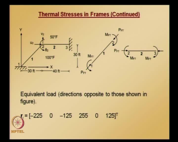
7 (Refer Slide Time: 10:34) Now, let us take an example; basically, this example is what you have already seen when we were solving 2D plane frames; only thing is earlier it was subjected to uniformly distributed load, here the same structure is subjected to temperature changes. Analyze the frame shown in figure below that is subjected to a temperature change that varies linearly from 100 Fahrenheit on the underside of the frame to 50 Fahrenheit on the top side. Assume a beam depth and also cross sectional area and moment of inertia and Young s modulus value, coefficient of thermal expansion - all these values are given both end FPS units and SI units; as you can see, these values are round numbers in FPS units whereas in SI units there all having some decimal places. It is the convenient to work in FPS units, so let us work this problem out in FPS units. The frame is shown in the first figure and the node numbers and element numbers are shown, as you can see from the figure that node 1 and node 3 are constrained. All the degrees of freedom at node 1 and node 3 are 0; the second figure shows the fixed end forces due to temperature change. This is different from what we have seen when we are looking at the concept just few minutes back; there, the top surface temperature is assumed to be higher than bottom surface temperature, here the top surface temperature is less than bottom surface temperature; so, all the fixed end forces, that is - and overall
8 temperature change rises; so, the axial forces will be in the same direction as we have seen when we were looking at this concept. But, the bending forces or the fixed end bending moments will be opposite direction; because, now the bottom side temperature is higher than top side temperature; so, all the fixed end forces due to this temperature change - the direction in which they will be acting are shown in figure b. (Refer Slide Time: 13:30) Now, by choosing arbitrarily, element 1 to go from node 1 to node 2 and choosing arbitrarily element 2 to go from node 2 to node 3; here, the local x axis and y axis are shown and also alpha is the angle between global x axis and local x axis measured in the counter clockwise direction that is also shown; alpha value can be calculated from the dimensions of the plane frame given; and you can see that element 2 is oriented along in the same direction as a global x axis. The angle between local and global x axis is 0; so, in this - for second element - the transformation matrix is going to be an identity matrix and whatever element quantities, that is, the element stiffness matrix in the local coordinate system will be same as in the global coordinate system; and also, the force vector calculated in local coordinate system for element 2 will be same as in the global coordinate system.

9 (Refer Slide Time: 15:04) Now, let us note down something; what is the mean temperature? This information is given - top side and bottom side temperature change; so, using those we can calculate what the mean temperature change is; and, once we have this we can calculate what is P FT; please note, that this P FT it is not dependent on length of the element; P FT value is going to be the same for the both element 1 and element 2. Here, the calculation for fixed end moment is also given, and if you carefully observe even fixed end moment equation there is no length quantity when you are calculating; basically - so fixed end axial forces and fixed end axial moment are independent of length of a element. So, these values remain same for both element 1 and element 2; using these values we can get the equivalent load vector. Direction of these fixed end forces are already shown in the figure - the transformation matrices and element global stiffness matrices are same as those in element stiffness matrix and local coordinate system and global coordinate system are same as those what you have already got when we were solving this problem subjected to uniformly distributed load in the last class. But, for completeness let us repeat those things again once again here. Now, let us start doing that and also note that only the right hand side load vector is going to be different, because now it is subjected to temperature changes.

10 (Refer Slide Time: 17:08) So, element 1 how can we calculate element equations the local coordinate system? We need to keep a note of what the nodal coordinates are. Once we know the nodal coordinates, we can calculate length of this element and also direction cosines - once we have these we can calculate what is the transformation matrix. Also we require some coefficients for stiffness matrix calculation, and please note that there is no load - distributed load - that is, uniformly distributed load applied on this member unlike in the previous example - only thing is now it is subjected to temperature change; so, these are the coefficients that are required for calculating the element stiffness matrix in the local coordinate system.
")
11 (Refer Slide Time: 18:21) (Refer Slide Time: 18:30)

 Similarly, element stiffness matrix in the local coordinate system - we can convert into the global coordinate system using the")
12 (Refer Slide Time: 18:55) Using these values we can calculate what the transformation matrix is, and we can also calculate what the stiffness matrix in the local coordinate system is; equivalent load vector using the values of P FT and M FT that we calculated we can get this equivalent load vector. This is in the local coordinate system and the equivalent load vector in the global coordinate system can be obtained using transformation matrix. (Refer Slide Time: 19:11) Similarly, element stiffness matrix in the local coordinate system - we can convert into the global coordinate system using the transformation matrix using this equation; only
 Similar calculations we need to repeat for element 2 - nodal coordinates for element 2; length, direction cosines and these are the coefficients that are required")
13 the upper triangular portion of this stiffness matrix is shown and lower triangular portion is similar to the upper triangular portion. (Refer Slide Time: 19:38) Similar calculations we need to repeat for element 2 - nodal coordinates for element 2; length, direction cosines and these are the coefficients that are required for assembling stiffness matrix. (Refer Slide Time: 19:53)

14 (Refer Slide Time: 20:14) Using the direction cosines, this is what is the transformation matrix that we get. Please note that the load vector is same for both element 1 and element 2; using the coefficients for stiffness matrix - this is the element stiffness matrix in the local coordinate system. This is the load vector and since the transformation matrix is identity matrix, local stiffness matrix - stiffness matrix in the local coordinate system - will be the same as stiffness matrix in the global coordinate system. Similarly, load vector - element load vector - in the local coordinate system will be same as in the global coordinate system; now, we have got all the information. And also note that this node numbering for this problem - only node 2 is not constrained, node 1 node 3 are constrained and element 1 is assume to go from node 1 to node 2 and element to go from node 2 to node 3. If you see the - imagine the final global equations - the global equation system - it is going to be 9 by 9 equation system; so, instead of assembling all the entire global equation system we can a smartly assemble or directly get the reduced equation system; and, the contribution from reduced stiffness matrix comes from the bottom or the lower quadrant of the element 1 stiffness matrix. To these reduced equations we get - or reduced stiffness matrix - we get contribution from upper quadrant of the element 2.

 (Refer Slide Time: 23:20) This is the assemblage for a load vector assembling contribution from two elements; so,")
15 Because of the boundary condition all the degrees of freedom at node 1 and node 3 are 0 there is no need to assemble corresponding rows and columns; therefore, since the specified values are 0 the corresponding columns will not contribute anything either; thus, only in the following global equations only the terms associated with node 2 are written. (Refer Slide Time: 22:54) (Refer Slide Time: 23:20) This is the assemblage for a load vector assembling contribution from two elements; so, global applied load vector is this and this can be simplified and we get this contribution

16 from both elements to the global load vector; the 3 by 3 global equations associated with degrees of freedom at node 2 are therefore as follows: so, in the global load vector that we got, whatever is there - the value at locations that is what is taken as the load vector for the reduced equations; and, the stiffness part is obtained by adding the lower quadrant of element 1 stiffness matrix and the upper quadrant of element 1 stiffness matrix; because, that is what is the contribution that goes into the locations of rows and columns in the global equation system; so, using these things we get this reduced equation system which we can solve for u2 v2 and theta 2 which are the unknowns at node 2. So, these are the values; now, we have got all the nodal values; so, the element forces can easily be obtained by, first determining the local displacements and then using the shape functions and their derivatives. (Refer Slide Time: 24:44) So, for element 1 the forces - element forces - this is the global element degrees of freedom; but, we want to calculate the element forces using shape functions and their derivatives; we need local degrees of freedom, so we can use transformation matrix and get the local corresponding local degrees of freedom.

 Similarly, we can calculate rest of the other two - that is, shear force and bending moment.")
17 (Refer Slide Time: 25:19) Once we get this d vector we can calculate axial effects, we can calculate using the components in the d vector, and the finite element shape functions; but, since the axial force is distributed or it is constant over the length of the element we need to apply fixed end correction - that is, thermal axial effect needs to be also taken into account when we are calculating axial force; so, using this formula we get axial force in element 1. (Refer Slide Time: 26:06) Similarly, we can calculate rest of the other two - that is, shear force and bending moment. Shear force, as I mentioned, because of thermal effects only bending moment

18 and axial forces will be developed which are going to be uniform or constant over the span of the element; no shear forces will be induced so no shear correction will be there - there is no fixed and shear correction for when you are calculating shear force; so, substituting all the values we get shear force with this value. (Refer Slide Time: 26:56) Using these sign conventions for internal moments and shear, we can draw the shear force diagram and bending moment for element 1 at any point along the length of element 1. Again, using finite element shape functions we can calculate once we know the nodal values; but, here we need to apply fixed and correction which we already calculated - M FT. So, applying that correction we get this and this is a function of s s is equal to 0 corresponds to node 1 s is equal to 1 corresponds to node 2. So, bending moment value at these two ends can be obtained by substituting s is equal to 0 and s is equal to 1; again, using the sign convention for internal moments we can draw the bending moment diagram for element 1.

19 (Refer Slide Time: 28:00) Similar calculations we can also repeat for element 2 - calculations for element 2 are similar to those for element 1 - the details are not given here explicitly, but the final axial force value shear force value and bending moment value are given. Here also, when you are calculating the forces - element forces - for element 2 for axial force and bending moment we need to apply the fixed end corrections; whereas, for shear force no such correction is required. Using these values we can draw free body diagram showing bending moment, shear force, and axial forces for element 1 and element 2 and we can easily verify these two elements independently or in equilibrium and also when they are put together whether they are in equilibrium - we can do that kind of verification.


20 (Refer Slide Time: 29:07) So, final forces are shown on the free body diagram and figure below. It can be easily verified that indeed each element itself is in equilibrium and also both elements put together - entire structure as in equilibrium, which is necessary for solution to be correct. Now, we will proceed; we have seen here 2D plane frames both subjected to uniformly distributed load and subjected to temperature changes and now let us move forward and let us look at 3D space frame element. (Refer Slide Time: 30:04)
21 The plane frame element can be generalized to analyze space frame structures. The local coordinate system for space frame element is chosen such that member is located along local x axis - you can see in the figure the member is located along local x axis. Principle axis of its cross section are oriented along y and z axis; local z axis is along the axis of maximum moment of inertia and local y axis is along minimum moment of inertia; element must include axial force effects and bending effects due to loads applied in x-z plane and x-y plane. In addition, element must also be able to resist torsional forces and similar to plane frame - 2D plane frame - element case, here also we assumed within small displacement theory all these effects - that is, axial effects, bending effects and torsional effects are assume to be uncoupled; final element equations are then just combination of equations treating these effects individually. Note that each node has 6 degrees of freedom now - three translations and three rotations and displacements and forces are positive along positive coordinate directions; positive directions for applied moments and rotations are based on right hand rule. Here, what I mean by right hand rule is - suppose if you put your thumb pointing in the positive direction of axis and the direction in which your fingers curl indicates the positive direction for moment or the rotation; so, that is what is right hand rule. When the thumb of your right hand is pointing towards positive coordinate direction the curl of your fingers defines positive direction for applied moments and rotations in right hand rule. Now, the 3D space frame element we shown here in both local coordinate system, and also all the local degrees of freedom are shown, and if you see the figure d1 d2 d3 or x y z displacement at node 1. Similarly, d7 d8 d9 or the x y z displacements at node 2 and d4 d5 d6 are rotations about x y z axis at node 1; and d10 d11 d12 are rotations about x y z axis at node 2; and q x are the q z and q y are the loads applied in x-z plane and x-y plane.

22 (Refer Slide Time: 33:35) Let us see what are the notations that will be using in these 3D space frame element; material and cross sectional properties notation for that - you are familiar with this Young s modulus denoted with E. (Refer Slide Time: 34:06) Now, one more thing is coming here - shear modulus, because torsional effects are also included for 3D space frame case and capital A is area of cross section - this also you are familiar with; length L is the length of element; and this is what I mentioned - the
 These are the rotations at node 1 node 2 and corresponding moments at node 1 node 2 are Mx1 My1 Mz1 Mx2 My2 Mz2;")
 Moments of inertia of cross section about y axis and moment of inertia of cross section about z axis is that denoted")
23 corresponding forces at node 1 or Fx1 Fy1 Fz1 similarly at node 2 are Fx2 Fy2 Fz2 in the directions x y z respectively. (Refer Slide Time: 34:27) These are the rotations at node 1 node 2 and corresponding moments at node 1 node 2 are Mx1 My1 Mz1 Mx2 My2 Mz2; since we have bending above both about the z axis - and y axis we need corresponding moments of inertia. (Refer Slide Time: 35:17) Moments of inertia of cross section about y axis and moment of inertia of cross section about z axis is that denoted with Iy and Iz; and here, the positive directions for internal

24 forces and moments are shown in this figure. If you observe this figure, a double added arrow convention is used to show moments; with this convention, if thumb of right hand is pointed in the direction of the arrow, then curl of fingers shows the direction of bending moment; so, these are the positive directions - the convention for positive directions - for internal forces and moments. Because, finally we will be using this sign convention after we calculate all the internal forces - that is, all the three component of forces at node 1 and node 2 and also all the three components of moment set node 1 and node 2. We can use the sign conventions to draw the free body diagram and also to draw bending moment, shear force, axial force and torsional moment, such kind of things we can draw using the sign convention. So, the positive directions for internal moments and internal shears are assumed to be in the direction, which is indicated in this figure; now, let us put together all the effects for assembling the final element equation for 3D space frame element which we will be using for solving problems of 3D space frame element. (Refer Slide Time: 37:21) Now, let us see what are the axial force effects. Axial force effects, you are already familiar with - it is given by this equation, except that we need to include the degrees of freedom and forces corresponding to the axial effects; so, using those we get this

25 equation; and, bending forces in x-y plane and figure illustrates the forces applied in x-y plane produce bending about z axis and using right hand rule rotation about z axis is equal to partial derivative of v with respect to x. The situation is exactly same as that for two-dimensional beam element; so, the equations that you already have for beam bending can be directly used here. If you adopt the same approach as we did for developing beam element equations - if you adopt that procedure for this case - you get exactly same equations. (Refer Slide Time: 38:18) So, for bending effects that are in the x-y plane it is given by this one - this equation. Since the rotation is about z-axis we need to use corresponding moment of inertia and we are calculating flexural rigidity EI. That is what is difference - there I z is used and in the load vector and also in the displacement vector corresponding values to the corresponding degrees of freedom values are shown in the equation; and, equivalent load vector for uniformly distributed load is given by this - this is also coming from the element equations that we developed for beam bending problem; because, the direction in which the rotation is taking place and also the direction in which the load is applied is the same as that from beam bending problem.

26 (Refer Slide Time: 39:45) Now, this is how bending effects or bending effects in the x-y plane - because of that we can calculate the contributions. Now, bending effects for forces in x-z plane: forces applied in x-z plane produce bending about y axis using right hand rule, the clockwise rotations about y axis are positive; so, the rotation about y axis is equal to now minus partial derivative of w with respect x. The shape functions for w are same as those for beam bending about z axis, which we have already seen; except that change in sign for rotation terms is required here; because, if you see here, our sign convention says that counter clockwise rotations are positive whereas here we have clockwise rotation - so theta y is minus partial derivative of w with respect x. Because of this clockwise rotation, even when we are interpolating, the shape functions for w are same as those for beam bending; but, for rotation, that is, the shape functions corresponding to partial derivative of w with respect x we need to have this negative sign. So, this is how w can be interpolating using finite element shape functions. If you see, only difference here is N1 and N4 are appended with negative sign and where N1 N2 N3 N4 are same as what you have already done- when we are solving a beam bending shape functions.


27 (Refer Slide Time: 41:43) Using the approach similar to what we did when we were deriving equations for beam bending problem - it can be easily shown that bending moment is given by this, and shear force is given by this; only difference is a negative sign is getting appended and substituting shape functions into beam bending potential - beam bending potential energy functional - the following equations can be easily derived by applying the stationarity condition. (Refer Slide Time: 42:32)
28 So, this equation gives us bending effects in x-z plane - because of forces in x-z plane; and, equivalent load vector due to uniformly distributed load is given by this; if it is some other load that we need to find the fixed end moments and shears and putting them together with a sign change we get the equivalent load vector similar to what we did for when we are solving beam bending case. So, we have already noted down the equations with corresponding degrees of freedom and forces for axial effects and also bending about x-y plane and x-z plane. (Refer Slide Time: 43:33) Now we are left with one more thing, which is torsional; so, torsional effects - a bar of cross section subjected to torsional moments or twisting moment at its end is shown in this figure, and the twisting we know that twisting moment per unit length is related to angle of twist through this equation.


29 (Refer Slide Time: 43:53) Where q is the twist or angular displacement, GJ is torsional stiffness similar to EI, EI is flexural rigidity, whereas, GJ is torsional rigidity or torsional stiffness, and G is the shear modulus and J is torsional constant - sometimes denoted by k T or I x. (Refer Slide Time: 44:44) This J value for various cross sections - you can refer any standard handbook; but, for simple cross sections you must have already learnt these things in your mechanics of material class circular cross section; J is polar moment of inertia which is some of I y and I z for other shapes J must be computed using methods of elasticity theory.


30 Formulas for few common shapes are given below; formulas for large number of different cross section shapes can be found in any standard handbook. (Refer Slide Time: 45:20) So, for a square having dimensions 2a by 2a J is given by this polar moment of inertia; similarly, for a rectangular section with the dimension shown that 2a 2b where a is greater than or equal to b polar moment of inertia is given by that equation, and if you have a section in which width is much larger than thickness - J is given by this. (Refer Slide Time: 46:01)

31 For angular rectangular section with dimensions b and d, thicknesses t1 t2, polar moment of inertia is given by this; and, for an I section with dimension shown there - width b depth d and thickness of flange and web t1 t2, J is given by this. (Refer Slide Time: 46:40) So, this is how you can get the torsional constant J; now, we need to look at the governing differential equations before we get element equations, because of the torsional effects. So, this equation, this is the governing differential equation for a bar subjected to twist; and, you can see this is a second order differential equations similar to 1 for axial deformation problem, and 0 is there on the right hand side and that is based on the assumption that there is no applied distributed twisting moment along the span of the member. Once we have this differential equation you can draw a similarity between this and the axial deformation problem; and, from its similarity to axial deformation problem it is easy to see that linear trial solution would give the following finite element equations; so, this is the element equations to capture the torsional effects. Now, we put together the element equations to capture axial force effects and bending effects - both in x-y plane and x-z plane. Now, we are able to derive for element equations for torsional effects, and when we are deriving all these equations we use the corresponding degrees of freedom and also corresponding forces; and, when we are starting out with this 3D space frame element details - we made an assumption that all

32 these effects that is axial effects bending effects and torsional effects are all uncoupled; so, combining all force 4 effects - now combining all the 4 effects - the following equations are obtained for 3 dimensional frame element in its local coordinate system. (Refer Slide Time: 48:47) Here, if you see all the displacement vector having all the degrees of freedom from all kinds of effects - all the 4 effects - and also the force vector has the corresponding forces due to all effects; and, this is similar to 2D plane frame element equation, except that bending about 2 planes is considered here and torsional effects are also considered here. (Refer Slide Time: 50:00)
33 If you see here, we have some coefficients - a1 a2 a3 and a4 and this equation can also be compactly written as kl dl is equal to rl; so, that equation can be written compactly in this manner, and also various coefficients are defined here; coming from axial effects and bending effects in both frames, and also torsional effects. In a next class we will see some numerical problems and before that we need to also look at - because we got the element equations in the local coordinate system, we need to see the transformation matrix details and how to transform this element equations into the global coordinate system - this local element equations into the global coordinate system - and then will solve a problem to understand various details, in the next class.
Finite Element Analysis Prof. Dr. B. N. Rao Department of Civil engineering Indian Institute of Technology, Madras. Module - 01 Lecture - 12
 Finite Element Analysis Prof. Dr. B. N. Rao Department of Civil engineering Indian Institute of Technology, Madras Module - 01 Lecture - 12 In the last class, we have seen there, how to calculate the displacements,
Finite Element Analysis Prof. Dr. B. N. Rao Department of Civil Engineering Indian Institute of Technology, Madras. Module - 01 Lecture - 11
 Finite Element Analysis Prof. Dr. B. N. Rao Department of Civil Engineering Indian Institute of Technology, Madras Module - 01 Lecture - 11 Last class, what we did is, we looked at a method called superposition
Finite Element Analysis Prof. Dr. B. N. Rao Department of Civil Engineering Indian Institute of Technology, Madras. Lecture - 06
 Finite Element Analysis Prof. Dr. B. N. Rao Department of Civil Engineering Indian Institute of Technology, Madras Lecture - 06 In the last lecture, we have seen a boundary value problem, using the formal
Finite Element Analysis Prof. Dr. B. N. Rao Department of Civil Engineering Indian Institute of Technology, Madras. Module - 01 Lecture - 16
 Finite Element Analysis Prof. Dr. B. N. Rao Department of Civil Engineering Indian Institute of Technology, Madras Module - 01 Lecture - 16 In the last lectures, we have seen one-dimensional boundary value
Finite Element Analysis Prof. Dr. B. N. Rao Department of Civil engineering Indian Institute of Technology, Madras. Module - 01 Lecture - 17
 Finite Element Analysis Prof. Dr. B. N. Rao Department of Civil engineering Indian Institute of Technology, Madras Module - 01 Lecture - 17 In the last class, we were looking at this general one-dimensional
Module 4 : Deflection of Structures Lecture 4 : Strain Energy Method
 Module 4 : Deflection of Structures Lecture 4 : Strain Energy Method Objectives In this course you will learn the following Deflection by strain energy method. Evaluation of strain energy in member under
Advanced Structural Analysis Prof. Devdas Menon Department of Civil Engineering Indian Institute of Technology, Madras
 Advanced Structural Analysis Prof. Devdas Menon Department of Civil Engineering Indian Institute of Technology, Madras Module No. # 5.1 Lecture No. # 27 Matrix Analysis of Beams and Grids Good morning,
Strength of Materials Prof. Dr. Suraj Prakash Harsha Mechanical and Industrial Engineering Department Indian Institute of Technology, Roorkee
 Strength of Materials Prof. Dr. Suraj Prakash Harsha Mechanical and Industrial Engineering Department Indian Institute of Technology, Roorkee Lecture - 28 Hi, this is Dr. S. P. Harsha from Mechanical and
Strength of Materials Prof S. K. Bhattacharya Department of Civil Engineering Indian Institute of Technology, Kharagpur Lecture - 18 Torsion - I
 Strength of Materials Prof S. K. Bhattacharya Department of Civil Engineering Indian Institute of Technology, Kharagpur Lecture - 18 Torsion - I Welcome to the first lesson of Module 4 which is on Torsion
Consider an elastic spring as shown in the Fig.2.4. When the spring is slowly
 .3 Strain Energy Consider an elastic spring as shown in the Fig..4. When the spring is slowly pulled, it deflects by a small amount u 1. When the load is removed from the spring, it goes back to the original
(Refer Slide Time: 01:00 01:01)
") Strength of Materials Prof: S.K.Bhattacharya Department of Civil Engineering Indian institute of Technology Kharagpur Lecture no 27 Lecture Title: Stresses in Beams- II Welcome to the second lesson of
Strength of Materials Prof: S.K.Bhattacharya Department of Civil Engineering Indian institute of Technology Kharagpur Lecture no 27 Lecture Title: Stresses in Beams- II Welcome to the second lesson of
Advanced Structural Analysis Prof. Devdas Menon Department of Civil Engineering Indian Institute of Technology, Madras
 Advanced Structural Analysis Prof. Devdas Menon Department of Civil Engineering Indian Institute of Technology, Madras Module - 6.2 Lecture - 34 Matrix Analysis of Plane and Space Frames Good morning.
Advanced Strength of Materials Prof. S. K. Maiti Department of Mechanical Engineering Indian Institute of Technology, Bombay.
 Advanced Strength of Materials Prof. S. K. Maiti Department of Mechanical Engineering Indian Institute of Technology, Bombay Lecture 32 Today we will talk about un symmetric bending. We have already studied
(Refer Slide Time: 00:55) (Refer Slide Time: 01:02)
 (Refer Slide Time: 01:02)") Advanced Structural Analysis Prof. Devdas Menon Department of Civil Engineering Indian Institute of Technology, Madras Module No. # 5.6 Lecture No. # 32 Matrix Analysis of Beams and Grids Good morning.
Advanced Structural Analysis Prof. Devdas Menon Department of Civil Engineering Indian Institute of Technology, Madras Module No. # 5.6 Lecture No. # 32 Matrix Analysis of Beams and Grids Good morning.
Advanced Structural Analysis Prof. Devdas Menon Department of Civil Engineering Indian Institute of Technology, Madras
 Advanced Structural Analysis Prof. Devdas Menon Department of Civil Engineering Indian Institute of Technology, Madras Module No. # 6.1 Lecture No. # 33 Matrix Analysis of Plane and Space Frames Good morning.
Strength of Materials Prof. S.K.Bhattacharya Dept. of Civil Engineering, I.I.T., Kharagpur Lecture No.26 Stresses in Beams-I
 Strength of Materials Prof. S.K.Bhattacharya Dept. of Civil Engineering, I.I.T., Kharagpur Lecture No.26 Stresses in Beams-I Welcome to the first lesson of the 6th module which is on Stresses in Beams
MITOCW MITRES2_002S10linear_lec07_300k-mp4
 MITOCW MITRES2_002S10linear_lec07_300k-mp4 The following content is provided under a Creative Commons license. Your support will help MIT OpenCourseWare continue to offer high quality educational resources
TORSION INCLUDING WARPING OF OPEN SECTIONS (I, C, Z, T AND L SHAPES)
") Page1 TORSION INCLUDING WARPING OF OPEN SECTIONS (I, C, Z, T AND L SHAPES) Restrained warping for the torsion of thin-wall open sections is not included in most commonly used frame analysis programs. Almost
Page1 TORSION INCLUDING WARPING OF OPEN SECTIONS (I, C, Z, T AND L SHAPES) Restrained warping for the torsion of thin-wall open sections is not included in most commonly used frame analysis programs. Almost
Theory and Practice of Rotor Dynamics Prof. Dr. Rajiv Tiwari Department of Mechanical Engineering Indian Institute of Technology Guwahati
 Theory and Practice of Rotor Dynamics Prof. Dr. Rajiv Tiwari Department of Mechanical Engineering Indian Institute of Technology Guwahati Module - 2 Simpul Rotors Lecture - 2 Jeffcott Rotor Model In the
Methods of Analysis. Force or Flexibility Method
 INTRODUCTION: The structural analysis is a mathematical process by which the response of a structure to specified loads is determined. This response is measured by determining the internal forces or stresses
Advanced Structural Analysis Prof. Devdas Menon Department of Civil Engineering Indian Institute of Technology, Madras Module No. # 2.
 Advanced Structural Analysis Prof. Devdas Menon Department of Civil Engineering Indian Institute of Technology, Madras Module No. # 2.2 Lecture No. # 08 Review of Basic Structural Analysis-2 Good morning
Engineering Mechanics Department of Mechanical Engineering Dr. G. Saravana Kumar Indian Institute of Technology, Guwahati
 Engineering Mechanics Department of Mechanical Engineering Dr. G. Saravana Kumar Indian Institute of Technology, Guwahati Module 3 Lecture 6 Internal Forces Today, we will see analysis of structures part
(Refer Slide Time: 2:43-03:02)
") Strength of Materials Prof. S. K. Bhattacharyya Department of Civil Engineering Indian Institute of Technology, Kharagpur Lecture - 34 Combined Stresses I Welcome to the first lesson of the eighth module
Strength of Materials Prof. S. K. Bhattacharyya Department of Civil Engineering Indian Institute of Technology, Kharagpur Lecture - 34 Combined Stresses I Welcome to the first lesson of the eighth module
Due Tuesday, September 21 st, 12:00 midnight
 Due Tuesday, September 21 st, 12:00 midnight The first problem discusses a plane truss with inclined supports. You will need to modify the MatLab software from homework 1. The next 4 problems consider
Structural Dynamics. Spring mass system. The spring force is given by and F(t) is the driving force. Start by applying Newton s second law (F=ma).
 is the driving force. Start by applying Newton s second law (F=ma).") Structural Dynamics Spring mass system. The spring force is given by and F(t) is the driving force. Start by applying Newton s second law (F=ma). We will now look at free vibrations. Considering the free
Structural Dynamics Spring mass system. The spring force is given by and F(t) is the driving force. Start by applying Newton s second law (F=ma). We will now look at free vibrations. Considering the free
FLEXIBILITY METHOD FOR INDETERMINATE FRAMES
 UNIT - I FLEXIBILITY METHOD FOR INDETERMINATE FRAMES 1. What is meant by indeterminate structures? Structures that do not satisfy the conditions of equilibrium are called indeterminate structure. These
Stress analysis of a stepped bar
 Stress analysis of a stepped bar Problem Find the stresses induced in the axially loaded stepped bar shown in Figure. The bar has cross-sectional areas of A ) and A ) over the lengths l ) and l ), respectively.
Advanced Structural Analysis Prof. Devdas Menon Department of Civil Engineering Indian Institute of Technology, Madras
 Advanced Structural Analysis Prof. Devdas Menon Department of Civil Engineering Indian Institute of Technology, Madras Module - 7.3 Lecture - 40 Analysis of elastic instability and second-order effects
Chapter 5 Structural Elements: The truss & beam elements
 Institute of Structural Engineering Page 1 Chapter 5 Structural Elements: The truss & beam elements Institute of Structural Engineering Page 2 Chapter Goals Learn how to formulate the Finite Element Equations
Chapter 2: Deflections of Structures
 Chapter 2: Deflections of Structures Fig. 4.1. (Fig. 2.1.) ASTU, Dept. of C Eng., Prepared by: Melkamu E. Page 1 (2.1) (4.1) (2.2) Fig.4.2 Fig.2.2 ASTU, Dept. of C Eng., Prepared by: Melkamu E. Page 2
STRESS STRAIN AND DEFORMATION OF SOLIDS, STATES OF STRESS
 1 UNIT I STRESS STRAIN AND DEFORMATION OF SOLIDS, STATES OF STRESS 1. Define: Stress When an external force acts on a body, it undergoes deformation. At the same time the body resists deformation. The
Lecture 8: Assembly of beam elements.
 ecture 8: Assembly of beam elements. 4. Example of Assemblage of Beam Stiffness Matrices. Place nodes at the load application points. Assembling the two sets of element equations (note the common elemental
Video lecture on Engineering Fracture Mechanics, Prof. K. Ramesh, IIT Madras 1
 Video lecture on Engineering Fracture Mechanics, Prof. K. Ramesh, IIT Madras 1 Module No.#02, Lecture No.#08: Elastic Strain Energy We will now move on to the chapter on energy release rate. In fact, many
Structural Dynamics Lecture Eleven: Dynamic Response of MDOF Systems: (Chapter 11) By: H. Ahmadian
 By: H. Ahmadian") Structural Dynamics Lecture Eleven: Dynamic Response of MDOF Systems: (Chapter 11) By: H. Ahmadian ahmadian@iust.ac.ir Dynamic Response of MDOF Systems: Mode-Superposition Method Mode-Superposition Method:
Structural Dynamics Lecture Eleven: Dynamic Response of MDOF Systems: (Chapter 11) By: H. Ahmadian ahmadian@iust.ac.ir Dynamic Response of MDOF Systems: Mode-Superposition Method Mode-Superposition Method:
Advanced Structural Analysis Prof. Devdas Menon Department of Civil Engineering Indian Institute of Technology, Madras
 Advanced Structural Analysis Prof. Devdas Menon Department of Civil Engineering Indian Institute of Technology, Madras Module - 5.2 Lecture - 28 Matrix Analysis of Beams and Grids (Refer Slide Time: 00:23)
Advanced Structural Analysis Prof. Devdas Menon Department of Civil Engineering Indian Institute of Technology, Madras
 Advanced Structural Analysis Prof. Devdas Menon Department of Civil Engineering Indian Institute of Technology, Madras Module - 4.3 Lecture - 24 Matrix Analysis of Structures with Axial Elements (Refer
Structural Analysis II Prof. P. Banerjee Department of Civil Engineering Indian Institute of Technology, Bombay Lecture 38
 Structural Analysis II Prof. P. Banerjee Department of Civil Engineering Indian Institute of Technology, Bombay Lecture 38 Good morning. We have been looking at influence lines for the last couple of lectures
Chapter 11. Displacement Method of Analysis Slope Deflection Method
 Chapter 11 Displacement ethod of Analysis Slope Deflection ethod Displacement ethod of Analysis Two main methods of analyzing indeterminate structure Force method The method of consistent deformations
Ph.D. Preliminary Examination Analysis
 UNIVERSITY OF CALIFORNIA, BERKELEY Spring Semester 2014 Dept. of Civil and Environmental Engineering Structural Engineering, Mechanics and Materials Name:......................................... Ph.D.
Level 7 Postgraduate Diploma in Engineering Computational mechanics using finite element method
 9210-203 Level 7 Postgraduate Diploma in Engineering Computational mechanics using finite element method You should have the following for this examination one answer book No additional data is attached
Advanced Structural Analysis Prof. Devdas Menon Department of Civil Engineering Indian Institute of Technology, Madras
 Advanced Structural Analysis Prof. Devdas Menon Department of Civil Engineering Indian Institute of Technology, Madras Module No. # 5.4 Lecture No. # 30 Matrix Analysis of Beams and Grids (Refer Slide
Lecture 8: Flexibility Method. Example
 ecture 8: lexibility Method Example The plane frame shown at the left has fixed supports at A and C. The frame is acted upon by the vertical load P as shown. In the analysis account for both flexural and
PURE BENDING. If a simply supported beam carries two point loads of 10 kn as shown in the following figure, pure bending occurs at segment BC.
 BENDING STRESS The effect of a bending moment applied to a cross-section of a beam is to induce a state of stress across that section. These stresses are known as bending stresses and they act normally
General elastic beam with an elastic foundation
 General elastic beam with an elastic foundation Figure 1 shows a beam-column on an elastic foundation. The beam is connected to a continuous series of foundation springs. The other end of the foundation
KINGS COLLEGE OF ENGINEERING DEPARTMENT OF MECHANICAL ENGINEERING QUESTION BANK. Subject code/name: ME2254/STRENGTH OF MATERIALS Year/Sem:II / IV
 KINGS COLLEGE OF ENGINEERING DEPARTMENT OF MECHANICAL ENGINEERING QUESTION BANK Subject code/name: ME2254/STRENGTH OF MATERIALS Year/Sem:II / IV UNIT I STRESS, STRAIN DEFORMATION OF SOLIDS PART A (2 MARKS)
Lecture 7: The Beam Element Equations.
 4.1 Beam Stiffness. A Beam: A long slender structural component generally subjected to transverse loading that produces significant bending effects as opposed to twisting or axial effects. MECH 40: Finite
QUESTION BANK DEPARTMENT: CIVIL SEMESTER: III SUBJECT CODE: CE2201 SUBJECT NAME: MECHANICS OF SOLIDS UNIT 1- STRESS AND STRAIN PART A
 DEPARTMENT: CIVIL SUBJECT CODE: CE2201 QUESTION BANK SEMESTER: III SUBJECT NAME: MECHANICS OF SOLIDS UNIT 1- STRESS AND STRAIN PART A (2 Marks) 1. Define longitudinal strain and lateral strain. 2. State
Engineering Mechanics Prof. U. S. Dixit Department of Mechanical Engineering Indian Institute of Technology, Guwahati Introduction to vibration
 Engineering Mechanics Prof. U. S. Dixit Department of Mechanical Engineering Indian Institute of Technology, Guwahati Introduction to vibration Module 15 Lecture 38 Vibration of Rigid Bodies Part-1 Today,
UNIT 1 STRESS STRAIN AND DEFORMATION OF SOLIDS, STATES OF STRESS 1. Define stress. When an external force acts on a body, it undergoes deformation.
 UNIT 1 STRESS STRAIN AND DEFORMATION OF SOLIDS, STATES OF STRESS 1. Define stress. When an external force acts on a body, it undergoes deformation. At the same time the body resists deformation. The magnitude
Ph.D. Preliminary Examination Analysis
 UNIVERSITY OF CALIFORNIA, BERKELEY Spring Semester 2017 Dept. of Civil and Environmental Engineering Structural Engineering, Mechanics and Materials Name:......................................... Ph.D.
Section 6: PRISMATIC BEAMS. Beam Theory
 Beam Theory There are two types of beam theory aailable to craft beam element formulations from. They are Bernoulli-Euler beam theory Timoshenko beam theory One learns the details of Bernoulli-Euler beam
BE Semester- I ( ) Question Bank (MECHANICS OF SOLIDS)
 Question Bank (MECHANICS OF SOLIDS)") BE Semester- I ( ) Question Bank (MECHANICS OF SOLIDS) All questions carry equal marks(10 marks) Q.1 (a) Write the SI units of following quantities and also mention whether it is scalar or vector: (i)
BE Semester- I ( ) Question Bank (MECHANICS OF SOLIDS) All questions carry equal marks(10 marks) Q.1 (a) Write the SI units of following quantities and also mention whether it is scalar or vector: (i)
Institute of Structural Engineering Page 1. Method of Finite Elements I. Chapter 2. The Direct Stiffness Method. Method of Finite Elements I
 Institute of Structural Engineering Page 1 Chapter 2 The Direct Stiffness Method Institute of Structural Engineering Page 2 Direct Stiffness Method (DSM) Computational method for structural analysis Matrix
EML4507 Finite Element Analysis and Design EXAM 1
 2-17-15 Name (underline last name): EML4507 Finite Element Analysis and Design EXAM 1 In this exam you may not use any materials except a pencil or a pen, an 8.5x11 formula sheet, and a calculator. Whenever
MECHANICS OF MATERIALS. Analysis of Beams for Bending
 MECHANICS OF MATERIALS Analysis of Beams for Bending By NUR FARHAYU ARIFFIN Faculty of Civil Engineering & Earth Resources Chapter Description Expected Outcomes Define the elastic deformation of an axially
Module 3. Analysis of Statically Indeterminate Structures by the Displacement Method
 odule 3 Analysis of Statically Indeterminate Structures by the Displacement ethod Lesson 14 The Slope-Deflection ethod: An Introduction Introduction As pointed out earlier, there are two distinct methods
CIVL 8/7117 Chapter 12 - Structural Dynamics 1/75. To discuss the dynamics of a single-degree-of freedom springmass
 CIV 8/77 Chapter - /75 Introduction To discuss the dynamics of a single-degree-of freedom springmass system. To derive the finite element equations for the time-dependent stress analysis of the one-dimensional
Structural Analysis III Compatibility of Displacements & Principle of Superposition
 Structural Analysis III Compatibility of Displacements & Principle of Superposition 2007/8 Dr. Colin Caprani, Chartered Engineer 1 1. Introduction 1.1 Background In the case of 2-dimensional structures
Chapter 1 General Introduction Instructor: Dr. Mürüde Çelikağ Office : CE Building Room CE230 and GE241
 CIVL222 STRENGTH OF MATERIALS Chapter 1 General Introduction Instructor: Dr. Mürüde Çelikağ Office : CE Building Room CE230 and GE241 E-mail : murude.celikag@emu.edu.tr 1. INTRODUCTION There are three
Quintic beam closed form matrices (revised 2/21, 2/23/12) General elastic beam with an elastic foundation
 General elastic beam with an elastic foundation") General elastic beam with an elastic foundation Figure 1 shows a beam-column on an elastic foundation. The beam is connected to a continuous series of foundation springs. The other end of the foundation
General elastic beam with an elastic foundation Figure 1 shows a beam-column on an elastic foundation. The beam is connected to a continuous series of foundation springs. The other end of the foundation
PES Institute of Technology
 PES Institute of Technology Bangalore south campus, Bangalore-5460100 Department of Mechanical Engineering Faculty name : Madhu M Date: 29/06/2012 SEM : 3 rd A SEC Subject : MECHANICS OF MATERIALS Subject
Name (Print) ME Mechanics of Materials Exam # 1 Date: October 5, 2016 Time: 8:00 10:00 PM
 ME Mechanics of Materials Exam # 1 Date: October 5, 2016 Time: 8:00 10:00 PM") Name (Print) (Last) (First) Instructions: ME 323 - Mechanics of Materials Exam # 1 Date: October 5, 2016 Time: 8:00 10:00 PM Circle your lecturer s name and your class meeting time. Gonzalez Krousgrill
Name (Print) (Last) (First) Instructions: ME 323 - Mechanics of Materials Exam # 1 Date: October 5, 2016 Time: 8:00 10:00 PM Circle your lecturer s name and your class meeting time. Gonzalez Krousgrill
External Work. When a force F undergoes a displacement dx in the same direction i as the force, the work done is
 Structure Analysis I Chapter 9 Deflection Energy Method External Work Energy Method When a force F undergoes a displacement dx in the same direction i as the force, the work done is du e = F dx If the
Review of Strain Energy Methods and Introduction to Stiffness Matrix Methods of Structural Analysis
 uke University epartment of Civil and Environmental Engineering CEE 42L. Matrix Structural Analysis Henri P. Gavin Fall, 22 Review of Strain Energy Methods and Introduction to Stiffness Matrix Methods
D : SOLID MECHANICS. Q. 1 Q. 9 carry one mark each. Q.1 Find the force (in kn) in the member BH of the truss shown.
 in the member BH of the truss shown.") D : SOLID MECHANICS Q. 1 Q. 9 carry one mark each. Q.1 Find the force (in kn) in the member BH of the truss shown. Q.2 Consider the forces of magnitude F acting on the sides of the regular hexagon having
D : SOLID MECHANICS Q. 1 Q. 9 carry one mark each. Q.1 Find the force (in kn) in the member BH of the truss shown. Q.2 Consider the forces of magnitude F acting on the sides of the regular hexagon having
Multi Linear Elastic and Plastic Link in SAP2000
 26/01/2016 Marco Donà Multi Linear Elastic and Plastic Link in SAP2000 1 General principles Link object connects two joints, i and j, separated by length L, such that specialized structural behaviour may
Lecture 4: PRELIMINARY CONCEPTS OF STRUCTURAL ANALYSIS. Introduction
 Introduction In this class we will focus on the structural analysis of framed structures. We will learn about the flexibility method first, and then learn how to use the primary analytical tools associated
Example 3.7 Consider the undeformed configuration of a solid as shown in Figure 3.60.
 162 3. The linear 3-D elasticity mathematical model The 3-D elasticity model is of great importance, since it is our highest order hierarchical model assuming linear elastic behavior. Therefore, it provides
Module 2. Analysis of Statically Indeterminate Structures by the Matrix Force Method
 Module 2 Analysis of Statically Indeterminate Structures by the Matrix Force Method Lesson 8 The Force Method of Analysis: Beams Instructional Objectives After reading this chapter the student will be
Dynamics of Ocean Structures Prof. Dr. Srinivasan Chandrasekaran Department of Ocean Engineering Indian Institute of Technology, Madras
 Dynamics of Ocean Structures Prof. Dr. Srinivasan Chandrasekaran Department of Ocean Engineering Indian Institute of Technology, Madras Module - 01 Lecture - 09 Characteristics of Single Degree - of -
3 Hours/100 Marks Seat No.
 *17304* 17304 14115 3 Hours/100 Marks Seat No. Instructions : (1) All questions are compulsory. (2) Illustrate your answers with neat sketches wherever necessary. (3) Figures to the right indicate full
k 21 k 22 k 23 k 24 k 31 k 32 k 33 k 34 k 41 k 42 k 43 k 44
 CE 6 ab Beam Analysis by the Direct Stiffness Method Beam Element Stiffness Matrix in ocal Coordinates Consider an inclined bending member of moment of inertia I and modulus of elasticity E subjected shear
Structural Dynamics Prof. P. Banerji Department of Civil Engineering Indian Institute of Technology, Bombay. Lecture - 1 Introduction
 Structural Dynamics Prof. P. Banerji Department of Civil Engineering Indian Institute of Technology, Bombay Lecture - 1 Introduction Hello, I am Pradipta Banerji from the department of civil engineering,
QUESTION BANK SEMESTER: III SUBJECT NAME: MECHANICS OF SOLIDS
 QUESTION BANK SEMESTER: III SUBJECT NAME: MECHANICS OF SOLIDS UNIT 1- STRESS AND STRAIN PART A (2 Marks) 1. Define longitudinal strain and lateral strain. 2. State Hooke s law. 3. Define modular ratio,
ME Final Exam. PROBLEM NO. 4 Part A (2 points max.) M (x) y. z (neutral axis) beam cross-sec+on. 20 kip ft. 0.2 ft. 10 ft. 0.1 ft.
 M (x) y. z (neutral axis) beam cross-sec+on. 20 kip ft. 0.2 ft. 10 ft. 0.1 ft.") ME 323 - Final Exam Name December 15, 2015 Instructor (circle) PROEM NO. 4 Part A (2 points max.) Krousgrill 11:30AM-12:20PM Ghosh 2:30-3:20PM Gonzalez 12:30-1:20PM Zhao 4:30-5:20PM M (x) y 20 kip ft 0.2
ME 323 - Final Exam Name December 15, 2015 Instructor (circle) PROEM NO. 4 Part A (2 points max.) Krousgrill 11:30AM-12:20PM Ghosh 2:30-3:20PM Gonzalez 12:30-1:20PM Zhao 4:30-5:20PM M (x) y 20 kip ft 0.2
By Dr. Mohammed Ramidh
 Engineering Materials Design Lecture.6 the design of beams By Dr. Mohammed Ramidh 6.1 INTRODUCTION Finding the shear forces and bending moments is an essential step in the design of any beam. we usually
2. Determine the deflection at C of the beam given in fig below. Use principal of virtual work. W L/2 B A L C
 CE-1259, Strength of Materials UNIT I STRESS, STRAIN DEFORMATION OF SOLIDS Part -A 1. Define strain energy density. 2. State Maxwell s reciprocal theorem. 3. Define proof resilience. 4. State Castigliano
Geometric Stiffness Effects in 2D and 3D Frames
 Geometric Stiffness Effects in D and 3D Frames CEE 41. Matrix Structural Analsis Department of Civil and Environmental Engineering Duke Universit Henri Gavin Fall, 1 In situations in which deformations
Soil Dynamics Prof. Deepankar Choudhury Department of Civil Engineering Indian Institute of Technology, Bombay
 Soil Dynamics Prof. Deepankar Choudhury Department of Civil Engineering Indian Institute of Technology, Bombay Module - 5 Machine Foundations Lecture - 31 EHS Theory, Vibrational Control Let us start our
Strength of Materials II (Mechanics of Materials) (SI Units) Dr. Ashraf Alfeehan
 (SI Units) Dr. Ashraf Alfeehan") Strength of Materials II (Mechanics of Materials) (SI Units) Dr. Ashraf Alfeehan 2017-2018 Mechanics of Material II Text Books Mechanics of Materials, 10th edition (SI version), by: R. C. Hibbeler, 2017
Strength of Materials II (Mechanics of Materials) (SI Units) Dr. Ashraf Alfeehan 2017-2018 Mechanics of Material II Text Books Mechanics of Materials, 10th edition (SI version), by: R. C. Hibbeler, 2017
Beam Design and Deflections
 Beam Design and Deflections tation: a = name for width dimension A = name for area Areq d-adj = area required at allowable stress when shear is adjusted to include self weight Aweb = area of the web of
Design of Steel Structures Prof. Damodar Maity Department of Civil Engineering Indian Institute of Technology, Guwahati
 Design of Steel Structures Prof. Damodar Maity Department of Civil Engineering Indian Institute of Technology, Guwahati Module 7 Gantry Girders and Plate Girders Lecture - 3 Introduction to Plate girders
Institute of Structural Engineering Page 1. Method of Finite Elements I. Chapter 2. The Direct Stiffness Method. Method of Finite Elements I
 Institute of Structural Engineering Page 1 Chapter 2 The Direct Stiffness Method Institute of Structural Engineering Page 2 Direct Stiffness Method (DSM) Computational method for structural analysis Matrix
Advanced Structural Analysis EGF Section Properties and Bending
 Advanced Structural Analysis EGF316 3. Section Properties and Bending 3.1 Loads in beams When we analyse beams, we need to consider various types of loads acting on them, for example, axial forces, shear
2 marks Questions and Answers
 1. Define the term strain energy. A: Strain Energy of the elastic body is defined as the internal work done by the external load in deforming or straining the body. 2. Define the terms: Resilience and
Theory & Practice of Rotor Dynamics Prof. Rajiv Tiwari Department of Mechanical Engineering Indian Institute of Technology Guwahati
 Theory & Practice of Rotor Dynamics Prof. Rajiv Tiwari Department of Mechanical Engineering Indian Institute of Technology Guwahati Module - 5 Torsional Vibrations Lecture - 4 Transfer Matrix Approach
 UNIT III DEFLECTION OF BEAMS 1. What are the methods for finding out the slope and deflection at a section? The important methods used for finding out the slope and deflection at a section in a loaded
Chapter 2 Basis for Indeterminate Structures
 Chapter - Basis for the Analysis of Indeterminate Structures.1 Introduction... 3.1.1 Background... 3.1. Basis of Structural Analysis... 4. Small Displacements... 6..1 Introduction... 6.. Derivation...
CHAPTER -6- BENDING Part -1-
 Ishik University / Sulaimani Civil Engineering Department Mechanics of Materials CE 211 CHAPTER -6- BENDING Part -1-1 CHAPTER -6- Bending Outlines of this chapter: 6.1. Chapter Objectives 6.2. Shear and
Basic Energy Principles in Stiffness Analysis
 Basic Energy Principles in Stiffness Analysis Stress-Strain Relations The application of any theory requires knowledge of the physical properties of the material(s) comprising the structure. We are limiting
Chapter 12 Plate Bending Elements. Chapter 12 Plate Bending Elements
 CIVL 7/8117 Chapter 12 - Plate Bending Elements 1/34 Chapter 12 Plate Bending Elements Learning Objectives To introduce basic concepts of plate bending. To derive a common plate bending element stiffness
Introduction to Structural Member Properties
 Introduction to Structural Member Properties Structural Member Properties Moment of Inertia (I): a mathematical property of a cross-section (measured in inches 4 or in 4 ) that gives important information
Module 3. Analysis of Statically Indeterminate Structures by the Displacement Method
 odule 3 Analysis of Statically Indeterminate Structures by the Displacement ethod Lesson 21 The oment- Distribution ethod: rames with Sidesway Instructional Objectives After reading this chapter the student
Unit 15 Shearing and Torsion (and Bending) of Shell Beams
 of Shell Beams") Unit 15 Shearing and Torsion (and Bending) of Shell Beams Readings: Rivello Ch. 9, section 8.7 (again), section 7.6 T & G 126, 127 Paul A. Lagace, Ph.D. Professor of Aeronautics & Astronautics and Engineering
Unit 15 Shearing and Torsion (and Bending) of Shell Beams Readings: Rivello Ch. 9, section 8.7 (again), section 7.6 T & G 126, 127 Paul A. Lagace, Ph.D. Professor of Aeronautics & Astronautics and Engineering
Matrix Method of Structural Analysis Prof. Amit Shaw Department of Civil Engineering Indian Institute of Technology, Kharagpur
 Matrix Method of Structural Analysis Prof. Amit Shaw Department of Civil Engineering Indian Institute of Technology, Kharagpur Lecture 01 Introduction Hello everyone, welcome to the online course on Matrix
Shafts: Torsion of Circular Shafts Reading: Crandall, Dahl and Lardner 6.2, 6.3
 M9 Shafts: Torsion of Circular Shafts Reading: Crandall, Dahl and Lardner 6., 6.3 A shaft is a structural member which is long and slender and subject to a torque (moment) acting about its long axis. We
5. What is the moment of inertia about the x - x axis of the rectangular beam shown?
 1 of 5 Continuing Education Course #274 What Every Engineer Should Know About Structures Part D - Bending Strength Of Materials NOTE: The following question was revised on 15 August 2018 1. The moment
Post Graduate Diploma in Mechanical Engineering Computational mechanics using finite element method
 9210-220 Post Graduate Diploma in Mechanical Engineering Computational mechanics using finite element method You should have the following for this examination one answer book scientific calculator No
Virtual Work & Energy Methods. External Energy-Work Transformation
 External Energy-Work Transformation Virtual Work Many structural problems are statically determinate (support reactions & internal forces can be found by simple statics) Other methods are required when
Design of Steel Structures Dr. Damodar Maity Department of Civil Engineering Indian Institute of Technology, Guwahati
 Design of Steel Structures Dr. Damodar Maity Department of Civil Engineering Indian Institute of Technology, Guwahati Module - 6 Flexural Members Lecture 5 Hello today I am going to deliver the lecture