Physics 8 Monday, November 20, 2017
|
|
|
- Imogen Katrina Day
- 5 years ago
- Views:
Transcription
1 Physics 8 Monday, November 20, 2017 Pick up HW11 handout, due Dec 1 (Friday next week). This week, you re skimming/reading O/K ch8, which goes into more detail on beams. Since many people will be traveling Wednesday for Thanksgiving, I will spend Wednesday s class demonstrating Processing, which is a Java-like programming language designed for visual artists. I think learning to code is an essential part of a liberal-arts education, so I give you this opportunity to try it out for extra credit. Processing makes coding fun and visual: every program draws a picture. Today we continue discussing beams. After a few more days on beams, our last topic of the semester will be oscillations (a.k.a. vibration, periodic motion).
2 We stopped here on Friday. Sign conventions: V (x) > 0 when beam left of x is pulling up on beam right of x. M(x) > 0 when beam is smiling. Transverse shear V (x) is the running sum of forces on beam, from 0... x, where upward = positive. Bending moment M(x) is the torque exerted by each side of the beam, cut at x, on the other side; but beware of sign convention. V (x) = d dx M(x) The V diagram graphs the slope of the M diagram.
3 Draw V and M for this simply supported beam: V (x) > 0 when beam 0... x pulls up on beam x... L. M > 0 when beam smiles.
4 V (x) = d dx M(x) The shear (V ) diagram equals the slope of the moment (M) diagram. M(x) = V (x) dx But be careful about the M values at the ends depends how the beam is supported. A free, hinged, or roller-supported end has M = 0: support exerts no torque on that end. Fixed end of cantilever has M 0.
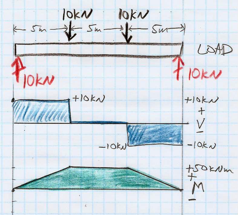
5 Let s try drawing load, V, and M diagrams for this simplysupported beam. Pretend the units are meters and kilonewtons rather than the original drawing s feet and kilopounds ( kips ).
6
7 Shear (V) and moment (M) diagrams: First draw a load diagram, which is an EFBD that shows all of the vertical forces acting on the beam. The shear diagram V (x) graphs the running sum of all vertical forces (both supports and loads) acting on the beam, from the left side up to x, where upward = positive, downward = negative. To draw the moment diagram M(x), note that V is the slope of M: V (x) = d dx M(x) The change in M from x 1 to x 2 is given by M 2 M 1 = (x 2 x 1 ) V average 1 2 If an end of a beam is unsupported ( free ), is hinge/pin supported, or is roller supported, then M = 0 at that end. You can only have M 0 at an end if the support at that end is capable of exerting a torque on the beam for example, the fixed end of a cantilever has M 0.
8 Draw shear (V ) and moment (M) diagrams for this beam! Tricky! First one needs to solve for the support ( reaction ) forces. Note: in solving for the support forces, you replace distributed load w with equivalent point load. But when you draw the load diagram to find V and M, you need to keep w in its original form.
9 Remember that V (x) is the running sum, from LHS to x, of vertical forces acting on the beam, with upward=positive.
10
11 Neat trick: M 2 M 1 = (V average 1 2 )(x 2 x 1 )
12 Draw load, V, and M diagrams for this simply supported beam with a partial uniform load.
13
14 Stopped here 11/20. We worked out V (x), but we still need to show how to go from V (x) to M(x) for this example.
15

16 Why do we care about these beam diagrams, anyway? Usually the floor of a structure must carry a specified weight per unit area. The beams (beams, girders, joists, etc.) must be strong enough to support this load without failing and must be stiff enough to support this load without excessive deflection.
17 Beam criteria: Normal stress in the extreme fibers of the beam (farthest from neutral surface) must be smaller than the allowable bending stress, F b, which depends on the material (wood, steel, etc.). This happens where M(x) has largest magnitude. Shear stress (in both y ( transverse ) and x ( longitudinal ) must be smaller than the allowable shear stress, F v, which is also a property of the material (wood, steel, etc.). This happens where V (x) has largest magnitude, and (surprisingly) is largest near the neutral surface. The above two are strength criteria. The third one is a stiffness criterion: The maximum deflection under load must satisfy the building code: typically y max < L/360. For a uniform load, this happens farthest away from the supports. If deflection is too large, plaster ceilings develop cracks, floors feel uncomfortably bouncy or sloped. The book also notes longitudinal buckling as a failure mode.
18 (In this illustration, bottom is in tension, top is in compression, as in a simply supported beam.)
 by deforming into a curved shape. (In this illustration, top is in tension, as in a cantilever.")
19 A big topic from this week s reading was to see how an initially horizontal beam responds to the bending moment M(x) by deforming into a curved shape. (In this illustration, top is in tension, as in a cantilever.)
20 Key idea: bending moment M 1 R, where R is the radius of curvature of the beam. For constant M, vertical lines converge toward common center of curvature. strain = L L 0 = y R where y = 0 is the neutral surface. So in this case y > 0 is in tension and y < 0 is in compression.
21 If you think of wood fibers running along the beam s axis, then the fibers above the neutral surface (y > 0) are stretched in proportion to y, and the fibers below the neutral surface (y < 0) are compressed in proportion to y. strain = L L = y R
22 Now remember that L L is called (axial) strain, and force per unit area is called stress. For an elastic material, strain (e) stress (f ). L L = 1 E Force Area = 1 E f e = 1 E f
23 In the elastic region, strain (e = L/L) is proportional to stress (f = F /A). f = Ee. The slope E is Young s modulus.
24 Plugging in f = Ee to the bending-beam diagram: y R = L L = e = f E we find the force-per-unit area (stress) exerted by the fibers is f = Ey R
25 The force-per-unit area (stress) exerted by the fibers is f = Ey R while the torque (bending moment dm, pivot about N.A.) exerted by each tiny fiber of area da is proportional to its lever arm y dm = y df = y f da = y ( Ey R ) da = E R y 2 da
26 So the bending moment M exerted by a curved beam is M = E y 2 da = EI R R where R is the curved beam s radius of curvature and I = y 2 da is the second moment of area a.k.a. area moment of inertia.
27 M = E y 2 da = EI R R Meanwhile, the vertical deflection of a point along the beam is related to its curvature by (in limit where R) 1 R d2 dx 2 so you can integrate the M(x) curve twice to get deflection d 2 dx 2 = M EI (x) = 1 EI dx M(x) dx
28 Calculus digression (not important but you may be curious): You may have seen in calculus that the curvature (which means 1/R, where R is the radius of curvature) of a function y = f (x) is 1 R = y (1 + (y ) 2 ) 3/2 We are working in the limit y 1, so That s how we arrived at 1 R y 1 R d2 dx 2
29 M = E y 2 da = EI R R Meanwhile, the vertical deflection of a point along the beam is related to its curvature by (in limit where R) 1 R d2 dx 2 so you can integrate the M(x) curve twice to get deflection d 2 dx 2 = M (x) = 1 dx M(x) dx EI EI
30 This Onouye/Kane figure writes y here for deflection, but I wrote for deflection on the preceding pages (and they usually do, too), because we were already using y for distance above the neutral surface. So you integrate M(x)/EI twice w.r.t. x to get the deflection (x). The bending moment M(x) = EI d 2 /dx 2, where E is Young s modulus and I is second moment of area.
31 The most common deflection results can be found in tables.
32 FYI, here s where that crazy (5wL 4 )/(384EI ) comes from! (continued on next page)
33 Here s where that crazy (5wL 4 )/(384EI ) comes from! The 2 integration constants can be tricky. Simply supported: (0) = (L) = 0. (For cantilever, (0) = (0) = 0 instead.)
34 Maximum deflection is one of several beam-design criteria. You can see now how it relates to the load and M(x) diagrams: max comes from integrating M(x)/(EI ) twice w.r.t. x to get (x). For point load P at the end of a cantilever (for example), you get max = PL3 3EI For uniform load w on simply-supported beam, you get max = 5wL4 384EI You just look these results up, or use a computer to calculate them. Deflection is proportional to load, and inversely proportional to Young s modulus and to the second moment of area. More load more deflection Stiffer material less deflection Cross-section with larger I = y 2 da less deflection
35 Another beam-design criterion is maximum bending stress: the fibers farthest from the neutral surface experience the largest tension or compression, hence largest bending stress. When we section the beam at x, bending moment M(x) is M = EI R which we can solve for the radius of curvature R = EI /M. Then the stress a distance y above the neutral surface is f = Ee = E y R = E y (EI /M) = M y I
36 The bending stress a distance y above the neutral surface is f = M y I The largest bending stress happens in the fibers farthest above or below the neutral surface. Call this largest distance y max c. f max = M c I = M (I /c) = M S The ratio S = I /c is called section modulus.
37 Bending stress in fibers farthest from neutral surface: f max = M (I /c) = M S So you sketch your load, V, and M diagrams, and you find M max, i.e. the largest magnitude of M(x). Then, the material you are using for beams (wood, steel, etc.) has a maximum allowable bending stress, F b. So then you look in your table of beam cross-sections and choose S S required = M max F b
38 Beam criteria: Normal stress in the extreme fibers of the beam (farthest from neutral surface) must be smaller than the allowable bending stress, F b, which depends on the material (wood, steel, etc.). This happens where M(x) has largest magnitude. Shear stress (in both y ( transverse ) and x ( longitudinal ) must be smaller than the allowable shear stress, F v, which is also a property of the material (wood, steel, etc.). This happens where V (x) has largest magnitude, and (surprisingly) is largest near the neutral surface. The above two are strength criteria. The third one is a stiffness criterion: The maximum deflection under load must satisfy the building code: typically y max < L/360. For a uniform load, this happens farthest away from the supports. If deflection is too large, plaster ceilings develop cracks, floors feel uncomfortably bouncy or sloped. The book also notes longitudinal buckling as a failure mode.
39 Maximum deflection is one of several beam-design criteria. max comes from integrating M(x)/(EI ) twice w.r.t. x to get (x). For uniform load w on simply-supported beam, you get max = 5wL4 384EI You just look these results up, or use a computer to calculate them. But I had great fun calculating the 5/384 myself! Deflection is proportional to load, and inversely proportional to Young s modulus and to the second moment of area. More load more deflection Stiffer material less deflection Cross-section with larger I = y 2 da less deflection Notice that putting a column in the middle of a long, uniformly loaded beam reduces max by a factor of 2 4 = 16. Alternatively, if you want to span a large, open space without intermediate columns or bearing walls, you need beams with large I.
 = y E y R da = E R y 2 da M = EI R Eliminate")
40 Bending beam into circular arc of radius R gives e = L L 0 = y R, strain e vs. distance y above the neutral surface. Hooke s Law f = Ee gives stress f = E y R Torque exerted by fibers of beam is M = y (f da) = y E y R da = E R y 2 da M = EI R Eliminate R f = M y = M I I /y
41 The bending stress a distance y above the neutral surface is f = M y I The largest bending stress happens in the fibers farthest above or below the neutral surface. Call this largest distance y max c. f max = M max c I = M max (I /c) = M max S The ratio S = I /c is called section modulus. The load diagram gives you M max. Each material (wood, steel, etc.) has allowed bending stress f max. Then S min tells you how big a beam you need.
42 Example (using metric units!): A cantilever beam has a span of 3.0 m with a single concentrated load of 100 kg at its unsupported end. If the beam is made of timber having allowable bending stress F b = N/m 2 (was 1600 psi in US units), what minimum section modulus is required? What is the smallest 2 dimensional lumber (width = 1.5 inch = m) whose cross-section satisfies this strength criterion? Would this beam also satisfy a max < L/240 (maximum deflection) stiffness criterion? If not, what standard 2 cross-section is needed instead? max = PL 3 /(3EI ) for a cantilever with concentrated load at end. Use Young s modulus E = N/m 2 for southern pine.
43
44 S min = M max f allowed = PL F b = (980 N)(3 m) N/m 2 = m 3 allowed = L 240 = 3.0 m 240 = m max = PL3 3EI I min = PL 3 3E allowed = m 4
45 I worked out b, h, I, and S = I /c values in metric units for standard 2 dimensional lumber. b b h h I = bh 3 /12 S = bh 2 / in.038 m 3.5 in.089 m m m in.038 m 5.5 in.140 m m m in.038 m 7.5 in.191 m m m in.038 m 9.5 in.241 m m m in.038 m 11.5 in.292 m m m 3 The numbers are nicer if you use centimeters instead of meters, but then you have the added hassle of remembering to convert back to meters in calculations. b b h h I = bh 3 /12 S = bh 2 / in 3.8 cm 3.5 in 8.9 cm 223 cm cm in 3.8 cm 5.5 in 14.0 cm 866 cm cm in 3.8 cm 7.5 in 19.1 cm 2195 cm cm in 3.8 cm 9.5 in 24.1 cm 4461 cm cm in 3.8 cm 11.5 in 29.2 cm 7913 cm cm 3
46 Minor variation on same problem: A cantilever beam has a span of 3.0 m with a uniform distributed load of 33.3 kg/m along its entire length. If we use timber with allowable bending stress F b = N/m 2, what minimum section modulus is required? What is the smallest 2 dimensional lumber (width = 1.5 inch = m) whose cross-section satisfies this strength criterion? Would this beam also satisfy a max < L/240 (maximum deflection) stiffness criterion? If not, what standard 2 cross-section is needed instead? max = wl 4 /(8EI ) for a cantilever with uniform load. Use Young s modulus E = N/m 2 for southern pine.
47
48 S min = M max f allowed = wl2 /2 F b = (326 N/m)(3 m)2 / N/m 2 = m 3 allowed = L 240 = 3.0 m 240 = m max = wl4 8EI I min = wl 4 8E allowed = m 4
49 (Here s a homework problem from ARCH 435.) Actually, Home Depot s 2 10 really is 9.5 inches deep, not 9.25 inches, and 2 12 really is 11.5 inches deep.
50 A timber floor system uses joists made of 2 10 dimensional lumber. Each joist spans a length of 4.27 m (simply supported). The floor carries a load of 2400 N/m 2. At what spacing should the joists be placed, in order not to exceed allowable bending stress F b = kn/m 2 ( N/m 2 )? (We should get an answer around 24 inches = 0.61 meters.)
51
52
53
54 If we have time left, let s solve this truss problem together. It s actually pretty quick, using method of sections. First solve for vertical support force at A, then analyze left side of section.
55
56 Physics 8 Monday, November 20, 2017 Pick up HW11 handout, due Dec 1 (Friday next week). This week, you re skimming/reading O/K ch8, which goes into more detail on beams. Since many people will be traveling Wednesday for Thanksgiving, I will spend Wednesday s class demonstrating Processing, which is a Java-like programming language designed for visual artists. I think learning to code is an essential part of a liberal-arts education, so I give you this opportunity to try it out for extra credit. Processing makes coding fun and visual: every program draws a picture. Today we continue discussing beams. After a few more days on beams, our last topic of the semester will be oscillations (a.k.a. vibration, periodic motion).
Physics 8 Wednesday, November 29, 2017
 Physics 8 Wednesday, November 29, 2017 HW11 due this Friday, Dec 1. After another day or two on beams, our last topic of the semester will be oscillations (a.k.a. vibration, periodic motion). Toward that
Physics 8 Monday, November 23, 2015
 Physics 8 Monday, November 23, 2015 Handing out HW11, due Friday, December 4. One or two more beam-related examples, then we ll move on to oscillations ( periodic motion ). This week s reading is Mazur
Physics 8 Wednesday, November 18, 2015
 Physics 8 Wednesday, November 18, 2015 Remember HW10 due Friday. For this week s homework help, I will show up Wednesday, DRL 2C4, 4pm-6pm (when/where you normally find Camilla), and Camilla will show
Physics 8 Wednesday, November 20, 2013
 Physics 8 Wednesday, November 20, 2013 I plan next time to use Statics & Strength of Materials for Architecture & Building Construction by Onouye & Kane for these few weeks supplemental topics. Used copies
[8] Bending and Shear Loading of Beams
![[8] Bending and Shear Loading of Beams](/thumbs/92/110949676.jpg "[8] Bending and Shear Loading of Beams") [8] Bending and Shear Loading of Beams Page 1 of 28 [8] Bending and Shear Loading of Beams [8.1] Bending of Beams (will not be covered in class) [8.2] Bending Strain and Stress [8.3] Shear in Straight
[8] Bending and Shear Loading of Beams Page 1 of 28 [8] Bending and Shear Loading of Beams [8.1] Bending of Beams (will not be covered in class) [8.2] Bending Strain and Stress [8.3] Shear in Straight
Beam Design and Deflections
 Beam Design and Deflections tation: a = name for width dimension A = name for area Areq d-adj = area required at allowable stress when shear is adjusted to include self weight Aweb = area of the web of
QUESTION BANK SEMESTER: III SUBJECT NAME: MECHANICS OF SOLIDS
 QUESTION BANK SEMESTER: III SUBJECT NAME: MECHANICS OF SOLIDS UNIT 1- STRESS AND STRAIN PART A (2 Marks) 1. Define longitudinal strain and lateral strain. 2. State Hooke s law. 3. Define modular ratio,
QUESTION BANK DEPARTMENT: CIVIL SEMESTER: III SUBJECT CODE: CE2201 SUBJECT NAME: MECHANICS OF SOLIDS UNIT 1- STRESS AND STRAIN PART A
 DEPARTMENT: CIVIL SUBJECT CODE: CE2201 QUESTION BANK SEMESTER: III SUBJECT NAME: MECHANICS OF SOLIDS UNIT 1- STRESS AND STRAIN PART A (2 Marks) 1. Define longitudinal strain and lateral strain. 2. State
Physics 8 Wednesday, October 28, 2015
 Physics 8 Wednesday, October 8, 015 HW7 (due this Friday will be quite easy in comparison with HW6, to make up for your having a lot to read this week. For today, you read Chapter 3 (analyzes cables, trusses,
Chapter 7: Bending and Shear in Simple Beams
 Chapter 7: Bending and Shear in Simple Beams Introduction A beam is a long, slender structural member that resists loads that are generally applied transverse (perpendicular) to its longitudinal axis.
Stress Analysis Lecture 4 ME 276 Spring Dr./ Ahmed Mohamed Nagib Elmekawy
 Stress Analysis Lecture 4 ME 76 Spring 017-018 Dr./ Ahmed Mohamed Nagib Elmekawy Shear and Moment Diagrams Beam Sign Convention The positive directions are as follows: The internal shear force causes a
PURE BENDING. If a simply supported beam carries two point loads of 10 kn as shown in the following figure, pure bending occurs at segment BC.
 BENDING STRESS The effect of a bending moment applied to a cross-section of a beam is to induce a state of stress across that section. These stresses are known as bending stresses and they act normally
Chapter 8: Bending and Shear Stresses in Beams
 Chapter 8: Bending and Shear Stresses in Beams Introduction One of the earliest studies concerned with the strength and deflection of beams was conducted by Galileo Galilei. Galileo was the first to discuss
D : SOLID MECHANICS. Q. 1 Q. 9 carry one mark each. Q.1 Find the force (in kn) in the member BH of the truss shown.
 in the member BH of the truss shown.") D : SOLID MECHANICS Q. 1 Q. 9 carry one mark each. Q.1 Find the force (in kn) in the member BH of the truss shown. Q.2 Consider the forces of magnitude F acting on the sides of the regular hexagon having
D : SOLID MECHANICS Q. 1 Q. 9 carry one mark each. Q.1 Find the force (in kn) in the member BH of the truss shown. Q.2 Consider the forces of magnitude F acting on the sides of the regular hexagon having
= 50 ksi. The maximum beam deflection Δ max is not = R B. = 30 kips. Notes for Strength of Materials, ET 200
 Notes for Strength of Materials, ET 00 Steel Six Easy Steps Steel beam design is about selecting the lightest steel beam that will support the load without exceeding the bending strength or shear strength
ENG2000 Chapter 7 Beams. ENG2000: R.I. Hornsey Beam: 1
 ENG2000 Chapter 7 Beams ENG2000: R.I. Hornsey Beam: 1 Overview In this chapter, we consider the stresses and moments present in loaded beams shear stress and bending moment diagrams We will also look at
ME Final Exam. PROBLEM NO. 4 Part A (2 points max.) M (x) y. z (neutral axis) beam cross-sec+on. 20 kip ft. 0.2 ft. 10 ft. 0.1 ft.
 M (x) y. z (neutral axis) beam cross-sec+on. 20 kip ft. 0.2 ft. 10 ft. 0.1 ft.") ME 323 - Final Exam Name December 15, 2015 Instructor (circle) PROEM NO. 4 Part A (2 points max.) Krousgrill 11:30AM-12:20PM Ghosh 2:30-3:20PM Gonzalez 12:30-1:20PM Zhao 4:30-5:20PM M (x) y 20 kip ft 0.2
ME 323 - Final Exam Name December 15, 2015 Instructor (circle) PROEM NO. 4 Part A (2 points max.) Krousgrill 11:30AM-12:20PM Ghosh 2:30-3:20PM Gonzalez 12:30-1:20PM Zhao 4:30-5:20PM M (x) y 20 kip ft 0.2
PERIYAR CENTENARY POLYTECHNIC COLLEGE PERIYAR NAGAR - VALLAM THANJAVUR. DEPARTMENT OF MECHANICAL ENGINEERING QUESTION BANK
 PERIYAR CENTENARY POLYTECHNIC COLLEGE PERIYAR NAGAR - VALLAM - 613 403 - THANJAVUR. DEPARTMENT OF MECHANICAL ENGINEERING QUESTION BANK Sub : Strength of Materials Year / Sem: II / III Sub Code : MEB 310
FIXED BEAMS IN BENDING
 FIXED BEAMS IN BENDING INTRODUCTION Fixed or built-in beams are commonly used in building construction because they possess high rigidity in comparison to simply supported beams. When a simply supported
 UNIT III DEFLECTION OF BEAMS 1. What are the methods for finding out the slope and deflection at a section? The important methods used for finding out the slope and deflection at a section in a loaded
OUTCOME 1 - TUTORIAL 3 BENDING MOMENTS. You should judge your progress by completing the self assessment exercises. CONTENTS
 Unit 2: Unit code: QCF Level: 4 Credit value: 15 Engineering Science L/601/1404 OUTCOME 1 - TUTORIAL 3 BENDING MOMENTS 1. Be able to determine the behavioural characteristics of elements of static engineering
[5] Stress and Strain
![[5] Stress and Strain](/thumbs/95/123344550.jpg "[5] Stress and Strain") [5] Stress and Strain Page 1 of 34 [5] Stress and Strain [5.1] Internal Stress of Solids [5.2] Design of Simple Connections (will not be covered in class) [5.3] Deformation and Strain [5.4] Hooke s Law
[5] Stress and Strain Page 1 of 34 [5] Stress and Strain [5.1] Internal Stress of Solids [5.2] Design of Simple Connections (will not be covered in class) [5.3] Deformation and Strain [5.4] Hooke s Law
Part 1 is to be completed without notes, beam tables or a calculator. DO NOT turn Part 2 over until you have completed and turned in Part 1.
 NAME CM 3505 Fall 06 Test 2 Part 1 is to be completed without notes, beam tables or a calculator. Part 2 is to be completed after turning in Part 1. DO NOT turn Part 2 over until you have completed and
Sub. Code:
 Important Instructions to examiners: ) The answers should be examined by key words and not as word-to-word as given in the model answer scheme. ) The model answer and the answer written by candidate may
STRESS STRAIN AND DEFORMATION OF SOLIDS, STATES OF STRESS
 1 UNIT I STRESS STRAIN AND DEFORMATION OF SOLIDS, STATES OF STRESS 1. Define: Stress When an external force acts on a body, it undergoes deformation. At the same time the body resists deformation. The
BEAM DEFLECTION THE ELASTIC CURVE
 BEAM DEFLECTION Samantha Ramirez THE ELASTIC CURVE The deflection diagram of the longitudinal axis that passes through the centroid of each cross-sectional area of a beam. Supports that apply a moment
Strength of Materials Prof. Dr. Suraj Prakash Harsha Mechanical and Industrial Engineering Department Indian Institute of Technology, Roorkee
 Strength of Materials Prof. Dr. Suraj Prakash Harsha Mechanical and Industrial Engineering Department Indian Institute of Technology, Roorkee Lecture - 28 Hi, this is Dr. S. P. Harsha from Mechanical and
UNIVERSITY OF BOLTON SCHOOL OF ENGINEERING. BEng (HONS) CIVIL ENGINEERING SEMESTER 1 EXAMINATION 2016/2017 MATHEMATICS & STRUCTURAL ANALYSIS
 CIVIL ENGINEERING SEMESTER 1 EXAMINATION 2016/2017 MATHEMATICS & STRUCTURAL ANALYSIS") TW21 UNIVERSITY OF BOLTON SCHOOL OF ENGINEERING BEng (HONS) CIVIL ENGINEERING SEMESTER 1 EXAMINATION 2016/2017 MATHEMATICS & STRUCTURAL ANALYSIS MODULE NO: CIE4011 Date: Wednesday 11 th January 2017 Time:
TW21 UNIVERSITY OF BOLTON SCHOOL OF ENGINEERING BEng (HONS) CIVIL ENGINEERING SEMESTER 1 EXAMINATION 2016/2017 MATHEMATICS & STRUCTURAL ANALYSIS MODULE NO: CIE4011 Date: Wednesday 11 th January 2017 Time:
Introduction to Structural Member Properties
 Introduction to Structural Member Properties Structural Member Properties Moment of Inertia (I): a mathematical property of a cross-section (measured in inches 4 or in 4 ) that gives important information
MECE 3321: Mechanics of Solids Chapter 6
 MECE 3321: Mechanics of Solids Chapter 6 Samantha Ramirez Beams Beams are long straight members that carry loads perpendicular to their longitudinal axis Beams are classified by the way they are supported
CE6306 STRENGTH OF MATERIALS TWO MARK QUESTIONS WITH ANSWERS ACADEMIC YEAR
 CE6306 STRENGTH OF MATERIALS TWO MARK QUESTIONS WITH ANSWERS ACADEMIC YEAR 2014-2015 UNIT - 1 STRESS, STRAIN AND DEFORMATION OF SOLIDS PART- A 1. Define tensile stress and tensile strain. The stress induced
Strength of Materials Prof. S.K.Bhattacharya Dept. of Civil Engineering, I.I.T., Kharagpur Lecture No.26 Stresses in Beams-I
 Strength of Materials Prof. S.K.Bhattacharya Dept. of Civil Engineering, I.I.T., Kharagpur Lecture No.26 Stresses in Beams-I Welcome to the first lesson of the 6th module which is on Stresses in Beams
Homework No. 1 MAE/CE 459/559 John A. Gilbert, Ph.D. Fall 2004
 Homework No. 1 MAE/CE 459/559 John A. Gilbert, Ph.D. 1. A beam is loaded as shown. The dimensions of the cross section appear in the insert. the figure. Draw a complete free body diagram showing an equivalent
Sample Questions for the ME328 Machine Design Final Examination Closed notes, closed book, no calculator.
 Sample Questions for the ME328 Machine Design Final Examination Closed notes, closed book, no calculator. The following is from the first page of the examination. I recommend you read it before the exam.
NAME: Given Formulae: Law of Cosines: Law of Sines:
 NME: Given Formulae: Law of Cosines: EXM 3 PST PROBLEMS (LESSONS 21 TO 28) 100 points Thursday, November 16, 2017, 7pm to 9:30, Room 200 You are allowed to use a calculator and drawing equipment, only.
structural analysis Excessive beam deflection can be seen as a mode of failure.
 Structure Analysis I Chapter 8 Deflections Introduction Calculation of deflections is an important part of structural analysis Excessive beam deflection can be seen as a mode of failure. Extensive glass
Physics 8 Friday, November 4, 2011
 Physics 8 Friday, November 4, 2011 Please turn in Homework 7. I will hand out solutions once everyone is here. The handout also includes HW8 and a page or two of updates to the equation sheet needed to
Purpose of this Guide: To thoroughly prepare students for the exact types of problems that will be on Exam 3.
 ES230 STRENGTH OF MTERILS Exam 3 Study Guide Exam 3: Wednesday, March 8 th in-class Updated 3/3/17 Purpose of this Guide: To thoroughly prepare students for the exact types of problems that will be on
COURSE TITLE : APPLIED MECHANICS & STRENGTH OF MATERIALS COURSE CODE : 4017 COURSE CATEGORY : A PERIODS/WEEK : 6 PERIODS/ SEMESTER : 108 CREDITS : 5
 COURSE TITLE : APPLIED MECHANICS & STRENGTH OF MATERIALS COURSE CODE : 4017 COURSE CATEGORY : A PERIODS/WEEK : 6 PERIODS/ SEMESTER : 108 CREDITS : 5 TIME SCHEDULE MODULE TOPICS PERIODS 1 Simple stresses
KINGS COLLEGE OF ENGINEERING DEPARTMENT OF MECHANICAL ENGINEERING QUESTION BANK. Subject code/name: ME2254/STRENGTH OF MATERIALS Year/Sem:II / IV
 KINGS COLLEGE OF ENGINEERING DEPARTMENT OF MECHANICAL ENGINEERING QUESTION BANK Subject code/name: ME2254/STRENGTH OF MATERIALS Year/Sem:II / IV UNIT I STRESS, STRAIN DEFORMATION OF SOLIDS PART A (2 MARKS)
STRENGTH OF MATERIALS-I. Unit-1. Simple stresses and strains
 STRENGTH OF MATERIALS-I Unit-1 Simple stresses and strains 1. What is the Principle of surveying 2. Define Magnetic, True & Arbitrary Meridians. 3. Mention different types of chains 4. Differentiate between
Downloaded from Downloaded from / 1
 PURWANCHAL UNIVERSITY III SEMESTER FINAL EXAMINATION-2002 LEVEL : B. E. (Civil) SUBJECT: BEG256CI, Strength of Material Full Marks: 80 TIME: 03:00 hrs Pass marks: 32 Candidates are required to give their
3. BEAMS: STRAIN, STRESS, DEFLECTIONS
 3. BEAMS: STRAIN, STRESS, DEFLECTIONS The beam, or flexural member, is frequently encountered in structures and machines, and its elementary stress analysis constitutes one of the more interesting facets
Unit Workbook 1 Level 4 ENG U8 Mechanical Principles 2018 UniCourse Ltd. All Rights Reserved. Sample
 Pearson BTEC Levels 4 Higher Nationals in Engineering (RQF) Unit 8: Mechanical Principles Unit Workbook 1 in a series of 4 for this unit Learning Outcome 1 Static Mechanical Systems Page 1 of 23 1.1 Shafts
Symmetric Bending of Beams
 Symmetric Bending of Beams beam is any long structural member on which loads act perpendicular to the longitudinal axis. Learning objectives Understand the theory, its limitations and its applications
Physics 8 Wednesday, September 27, 2017
 Physics 8 Wednesday, September 27, 2017 Remember HW #4 due this Friday (but Monday is OK, if you prefer). It covers Chapters 7 (interactions) and 8 (force). No HW problems next week. Homework study/help
Physics 8 Wednesday, October 25, 2017
 Physics 8 Wednesday, October 25, 2017 HW07 due Friday. It is mainly rotation, plus a couple of basic torque questions. And there are only 8 problems this week. For today, you read (in Perusall) Onouye/Kane
ENG1001 Engineering Design 1
 ENG1001 Engineering Design 1 Structure & Loads Determine forces that act on structures causing it to deform, bend, and stretch Forces push/pull on objects Structures are loaded by: > Dead loads permanent
Lab Exercise #5: Tension and Bending with Strain Gages
 Lab Exercise #5: Tension and Bending with Strain Gages Pre-lab assignment: Yes No Goals: 1. To evaluate tension and bending stress models and Hooke s Law. a. σ = Mc/I and σ = P/A 2. To determine material
2012 MECHANICS OF SOLIDS
 R10 SET - 1 II B.Tech II Semester, Regular Examinations, April 2012 MECHANICS OF SOLIDS (Com. to ME, AME, MM) Time: 3 hours Max. Marks: 75 Answer any FIVE Questions All Questions carry Equal Marks ~~~~~~~~~~~~~~~~~~~~~~
Review Lecture. AE1108-II: Aerospace Mechanics of Materials. Dr. Calvin Rans Dr. Sofia Teixeira De Freitas
 Review Lecture AE1108-II: Aerospace Mechanics of Materials Dr. Calvin Rans Dr. Sofia Teixeira De Freitas Aerospace Structures & Materials Faculty of Aerospace Engineering Analysis of an Engineering System
Mechanics in Energy Resources Engineering - Chapter 5 Stresses in Beams (Basic topics)
") Week 7, 14 March Mechanics in Energy Resources Engineering - Chapter 5 Stresses in Beams (Basic topics) Ki-Bok Min, PhD Assistant Professor Energy Resources Engineering i Seoul National University Shear
Week 7, 14 March Mechanics in Energy Resources Engineering - Chapter 5 Stresses in Beams (Basic topics) Ki-Bok Min, PhD Assistant Professor Energy Resources Engineering i Seoul National University Shear
Beam Bending Stresses and Shear Stress
 Beam Bending Stresses and Shear Stress Notation: A = name or area Aweb = area o the web o a wide lange section b = width o a rectangle = total width o material at a horizontal section c = largest distance
5. What is the moment of inertia about the x - x axis of the rectangular beam shown?
 1 of 5 Continuing Education Course #274 What Every Engineer Should Know About Structures Part D - Bending Strength Of Materials NOTE: The following question was revised on 15 August 2018 1. The moment
Advanced Structural Analysis Prof. Devdas Menon Department of Civil Engineering Indian Institute of Technology, Madras Module No. # 2.
 Advanced Structural Analysis Prof. Devdas Menon Department of Civil Engineering Indian Institute of Technology, Madras Module No. # 2.2 Lecture No. # 08 Review of Basic Structural Analysis-2 Good morning
CIV100 Mechanics. Module 5: Internal Forces and Design. by: Jinyue Zhang. By the end of this Module you should be able to:
 CIV100 Mechanics Module 5: Internal Forces and Design by: Jinyue Zhang Module Objective By the end of this Module you should be able to: Find internal forces of any structural members Understand how Shear
Strength of Materials Prof: S.K.Bhattacharya Dept of Civil Engineering, IIT, Kharagpur Lecture no 28 Stresses in Beams- III
 Strength of Materials Prof: S.K.Bhattacharya Dept of Civil Engineering, IIT, Kharagpur Lecture no 28 Stresses in Beams- III Welcome to the 3 rd lesson of the 6 th module which is on Stresses in Beams part
(Refer Slide Time: 01:00 01:01)
") Strength of Materials Prof: S.K.Bhattacharya Department of Civil Engineering Indian institute of Technology Kharagpur Lecture no 27 Lecture Title: Stresses in Beams- II Welcome to the second lesson of
Strength of Materials Prof: S.K.Bhattacharya Department of Civil Engineering Indian institute of Technology Kharagpur Lecture no 27 Lecture Title: Stresses in Beams- II Welcome to the second lesson of
Properties of Sections
 ARCH 314 Structures I Test Primer Questions Dr.-Ing. Peter von Buelow Properties of Sections 1. Select all that apply to the characteristics of the Center of Gravity: A) 1. The point about which the body
Physics 8 Friday, September 22, 2017
 Physics 8 Friday, September 22, 2017 HW #3 due today (but Monday is OK, if you prefer). It covers Chapters 4 (momentum) and 5 (energy). For Monday, read Ch9 (work). Mathematica is free (site license) for
UNIT 1 STRESS STRAIN AND DEFORMATION OF SOLIDS, STATES OF STRESS 1. Define stress. When an external force acts on a body, it undergoes deformation.
 UNIT 1 STRESS STRAIN AND DEFORMATION OF SOLIDS, STATES OF STRESS 1. Define stress. When an external force acts on a body, it undergoes deformation. At the same time the body resists deformation. The magnitude
ENGINEERING COUNCIL DIPLOMA LEVEL MECHANICS OF SOLIDS D209 TUTORIAL 3 - SHEAR FORCE AND BENDING MOMENTS IN BEAMS
 ENGINEERING COUNCIL DIPLOMA LEVEL MECHANICS OF SOLIDS D209 TUTORIAL 3 - SHEAR FORCE AND BENDING MOMENTS IN BEAMS You should judge your progress by completing the self assessment exercises. On completion
March 24, Chapter 4. Deflection and Stiffness. Dr. Mohammad Suliman Abuhaiba, PE
 Chapter 4 Deflection and Stiffness 1 2 Chapter Outline Spring Rates Tension, Compression, and Torsion Deflection Due to Bending Beam Deflection Methods Beam Deflections by Superposition Strain Energy Castigliano
Advanced Structural Analysis EGF Section Properties and Bending
 Advanced Structural Analysis EGF316 3. Section Properties and Bending 3.1 Loads in beams When we analyse beams, we need to consider various types of loads acting on them, for example, axial forces, shear
Design of Beams (Unit - 8)
") Design of Beams (Unit - 8) Contents Introduction Beam types Lateral stability of beams Factors affecting lateral stability Behaviour of simple and built - up beams in bending (Without vertical stiffeners)
Design of Beams (Unit - 8) Contents Introduction Beam types Lateral stability of beams Factors affecting lateral stability Behaviour of simple and built - up beams in bending (Without vertical stiffeners)
Discontinuous Distributions in Mechanics of Materials
 Discontinuous Distributions in Mechanics of Materials J.E. Akin, Rice University 1. Introduction The study of the mechanics of materials continues to change slowly. The student needs to learn about software
: APPLIED MECHANICS & STRENGTH OF MATERIALS COURSE CODE : 4021 COURSE CATEGORY : A PERIODS/ WEEK : 5 PERIODS/ SEMESTER : 75 CREDIT : 5 TIME SCHEDULE
 COURSE TITLE : APPLIED MECHANICS & STRENGTH OF MATERIALS COURSE CODE : 4021 COURSE CATEGORY : A PERIODS/ WEEK : 5 PERIODS/ SEMESTER : 75 CREDIT : 5 TIME SCHEDULE MODULE TOPIC PERIODS 1 Simple stresses
1.050: Beam Elasticity (HW#9)
") 1050: Beam Elasticity (HW#9) MIT 1050 (Engineering Mechanics I) Fall 2007 Instructor: Markus J BUEHER Due: November 14, 2007 Team Building and Team Work: We strongly encourage you to form Homework teams
1050: Beam Elasticity (HW#9) MIT 1050 (Engineering Mechanics I) Fall 2007 Instructor: Markus J BUEHER Due: November 14, 2007 Team Building and Team Work: We strongly encourage you to form Homework teams
CHAPTER OBJECTIVES Use various methods to determine the deflection and slope at specific pts on beams and shafts: 2. Discontinuity functions
 1. Deflections of Beams and Shafts CHAPTER OBJECTIVES Use various methods to determine the deflection and slope at specific pts on beams and shafts: 1. Integration method. Discontinuity functions 3. Method
By Dr. Mohammed Ramidh
 Engineering Materials Design Lecture.6 the design of beams By Dr. Mohammed Ramidh 6.1 INTRODUCTION Finding the shear forces and bending moments is an essential step in the design of any beam. we usually
Problem d d d B C E D. 0.8d. Additional lecturebook examples 29 ME 323
 Problem 9.1 Two beam segments, AC and CD, are connected together at C by a frictionless pin. Segment CD is cantilevered from a rigid support at D, and segment AC has a roller support at A. a) Determine
Ph.D. Preliminary Examination Analysis
 UNIVERSITY OF CALIFORNIA, BERKELEY Spring Semester 2014 Dept. of Civil and Environmental Engineering Structural Engineering, Mechanics and Materials Name:......................................... Ph.D.
Mechanics of Materials II. Chapter III. A review of the fundamental formulation of stress, strain, and deflection
 Mechanics of Materials II Chapter III A review of the fundamental formulation of stress, strain, and deflection Outline Introduction Assumtions and limitations Axial loading Torsion of circular shafts
MECHANICS OF MATERIALS. Prepared by Engr. John Paul Timola
 MECHANICS OF MATERIALS Prepared by Engr. John Paul Timola Mechanics of materials branch of mechanics that studies the internal effects of stress and strain in a solid body. stress is associated with the
UNIT-I STRESS, STRAIN. 1. A Member A B C D is subjected to loading as shown in fig determine the total elongation. Take E= 2 x10 5 N/mm 2
 UNIT-I STRESS, STRAIN 1. A Member A B C D is subjected to loading as shown in fig determine the total elongation. Take E= 2 x10 5 N/mm 2 Young s modulus E= 2 x10 5 N/mm 2 Area1=900mm 2 Area2=400mm 2 Area3=625mm
Application of Finite Element Method to Create Animated Simulation of Beam Analysis for the Course of Mechanics of Materials
 International Conference on Engineering Education and Research "Progress Through Partnership" 4 VSB-TUO, Ostrava, ISSN 156-35 Application of Finite Element Method to Create Animated Simulation of Beam
2. Determine the deflection at C of the beam given in fig below. Use principal of virtual work. W L/2 B A L C
 CE-1259, Strength of Materials UNIT I STRESS, STRAIN DEFORMATION OF SOLIDS Part -A 1. Define strain energy density. 2. State Maxwell s reciprocal theorem. 3. Define proof resilience. 4. State Castigliano
Materials: engineering, science, processing and design, 2nd edition Copyright (c)2010 Michael Ashby, Hugh Shercliff, David Cebon.
2010 Michael Ashby, Hugh Shercliff, David Cebon.") Modes of Loading (1) tension (a) (2) compression (b) (3) bending (c) (4) torsion (d) and combinations of them (e) Figure 4.2 1 Standard Solution to Elastic Problems Three common modes of loading: (a) tie
Modes of Loading (1) tension (a) (2) compression (b) (3) bending (c) (4) torsion (d) and combinations of them (e) Figure 4.2 1 Standard Solution to Elastic Problems Three common modes of loading: (a) tie
twenty one concrete construction: shear & deflection ARCHITECTURAL STRUCTURES: FORM, BEHAVIOR, AND DESIGN DR. ANNE NICHOLS SUMMER 2014 lecture
 ARCHITECTURAL STRUCTURES: FORM, BEHAVIOR, AND DESIGN DR. ANNE NICHOLS SUMMER 2014 lecture twenty one concrete construction: Copyright Kirk Martini shear & deflection Concrete Shear 1 Shear in Concrete
3.032 Problem Set 1 Fall 2007 Due: Start of Lecture,
 3.032 Problem Set 1 Fall 2007 Due: Start of Lecture, 09.14.07 1. The I35 bridge in Minneapolis collapsed in Summer 2007. The failure apparently occurred at a pin in the gusset plate of the truss supporting
CH. 4 BEAMS & COLUMNS
 CH. 4 BEAMS & COLUMNS BEAMS Beams Basic theory of bending: internal resisting moment at any point in a beam must equal the bending moments produced by the external loads on the beam Rx = Cc + Tt - If the
Chapter 5 Elastic Strain, Deflection, and Stability 1. Elastic Stress-Strain Relationship
 Chapter 5 Elastic Strain, Deflection, and Stability Elastic Stress-Strain Relationship A stress in the x-direction causes a strain in the x-direction by σ x also causes a strain in the y-direction & z-direction
SERVICEABILITY OF BEAMS AND ONE-WAY SLABS
 CHAPTER REINFORCED CONCRETE Reinforced Concrete Design A Fundamental Approach - Fifth Edition Fifth Edition SERVICEABILITY OF BEAMS AND ONE-WAY SLABS A. J. Clark School of Engineering Department of Civil
Engineering Mechanics Department of Mechanical Engineering Dr. G. Saravana Kumar Indian Institute of Technology, Guwahati
 Engineering Mechanics Department of Mechanical Engineering Dr. G. Saravana Kumar Indian Institute of Technology, Guwahati Module 3 Lecture 6 Internal Forces Today, we will see analysis of structures part
Mechanics of Materials Primer
 Mechanics of Materials rimer Notation: A = area (net = with holes, bearing = in contact, etc...) b = total width of material at a horizontal section d = diameter of a hole D = symbol for diameter E = modulus
SSC-JE MAINS ONLINE TEST SERIES / CIVIL ENGINEERING SOM + TOS
 SSC-JE MAINS ONLINE TEST SERIES / CIVIL ENGINEERING SOM + TOS Time Allowed:2 Hours Maximum Marks: 300 Attention: 1. Paper consists of Part A (Civil & Structural) Part B (Electrical) and Part C (Mechanical)
Wood Design. fv = shear stress fv-max = maximum shear stress Fallow = allowable stress Fb = tabular bending strength = allowable bending stress
 Wood Design Notation: a = name for width dimension A = name for area Areq d-adj = area required at allowable stress when shear is adjusted to include self weight b = width of a rectangle = name for height
CHAPTER 4: BENDING OF BEAMS
 (74) CHAPTER 4: BENDING OF BEAMS This chapter will be devoted to the analysis of prismatic members subjected to equal and opposite couples M and M' acting in the same longitudinal plane. Such members are
Physics 8 Monday, December 4, 2017
 Physics 8 Monday, December 4, 2017 HW12 due Friday. Grace will do a review session Dec 12 or 13. When? I will do a review session: afternoon Dec 17? Evening Dec 18? Wednesday, I will hand out the practice
6. Bending CHAPTER OBJECTIVES
 CHAPTER OBJECTIVES Determine stress in members caused by bending Discuss how to establish shear and moment diagrams for a beam or shaft Determine largest shear and moment in a member, and specify where
7.4 The Elementary Beam Theory
 7.4 The Elementary Beam Theory In this section, problems involving long and slender beams are addressed. s with pressure vessels, the geometry of the beam, and the specific type of loading which will be
Danger of Snow in the Sunshine State
 Undergraduate Journal of Mathematical Modeling: One + Two Volume 7 2017 Spring 2017 Issue 2 Article 2 Danger of Snow in the Sunshine State Dmitrii Karpenko University of South Florida Advisors: Arcadii
3 Hours/100 Marks Seat No.
 *17304* 17304 14115 3 Hours/100 Marks Seat No. Instructions : (1) All questions are compulsory. (2) Illustrate your answers with neat sketches wherever necessary. (3) Figures to the right indicate full
CIVIL DEPARTMENT MECHANICS OF STRUCTURES- ASSIGNMENT NO 1. Brach: CE YEAR:
 MECHANICS OF STRUCTURES- ASSIGNMENT NO 1 SEMESTER: V 1) Find the least moment of Inertia about the centroidal axes X-X and Y-Y of an unequal angle section 125 mm 75 mm 10 mm as shown in figure 2) Determine
Section Downloads. Design Process. Design Principles Outline. Basic Design Principles. Design Process. Section 06: Design Principles.
 Section Downloads Section 06: Design Principles 1 Download & Print TTT I Sec 06 Slides TTT I Sec 06 Handout Section 05 Truss Materials Design Values PS 20 Section 01 TPI 1-2007 Selection 6.4.2 Repetitive
PES Institute of Technology
 PES Institute of Technology Bangalore south campus, Bangalore-5460100 Department of Mechanical Engineering Faculty name : Madhu M Date: 29/06/2012 SEM : 3 rd A SEC Subject : MECHANICS OF MATERIALS Subject
ε t increases from the compressioncontrolled Figure 9.15: Adjusted interaction diagram
 CHAPTER NINE COLUMNS 4 b. The modified axial strength in compression is reduced to account for accidental eccentricity. The magnitude of axial force evaluated in step (a) is multiplied by 0.80 in case
2 marks Questions and Answers
 1. Define the term strain energy. A: Strain Energy of the elastic body is defined as the internal work done by the external load in deforming or straining the body. 2. Define the terms: Resilience and
7.5 Elastic Buckling Columns and Buckling
 7.5 Elastic Buckling The initial theory of the buckling of columns was worked out by Euler in 1757, a nice example of a theory preceding the application, the application mainly being for the later invented
7 TRANSVERSE SHEAR transverse shear stress longitudinal shear stresses
 7 TRANSVERSE SHEAR Before we develop a relationship that describes the shear-stress distribution over the cross section of a beam, we will make some preliminary remarks regarding the way shear acts within