Steel Structures Design and Drawing Lecture Notes
|
|
|
- Isaac Casey
- 6 years ago
- Views:
Transcription
1 Steel Structures Design and Drawing Lecture Notes INTRODUCTION When the need for a new structure arises, an individual or agency has to arrange the funds required for its construction. The individual or agency henceforth referred to as the owner then approaches an architect. The architect plans the layout so as to satisfy the functional requirements and also ensures that the structure is aesthetically pleasing and economically feasible. In this process, the architect often decides the material and type of construction as well. The plan is then given to a structural engineer who is expected to do locate the structural elements so as to cause least interference to the function and aesthetics of the structure. He then makes the strength calculations to ensure safety and serviceability of the structure. This process is known as structural design. Finally, the structural elements are fabricated and erected by the contractor. If all the people work as a team then a safe, useful, aesthetic and economical structure is conceived. However in practice, many structures fulfill the requirements only partially because of inadequate coordination between the people involved and their lack of knowledge of the capabilities and limitations of their own and that of others. Since a structural engineer is central to this team, it is necessary for him to have adequate knowledge of the architects and contractors work. It is his responsibility to advise both the architect and the contractor about the possibilities of achieving good structures with economy. Ever since steel began to be used in the construction of structures, it has made possible some of the grandest structures both in the past and also in the present day (Fig. 1.1). In the following paragraph, some of the aspects of steel structures, which every structural engineer should know, are briefly discussed. Steel is by far the most useful material for building structures with strength of approximately ten times that of concrete, steel is the ideal material for modern construction. Due to its large strength to weight ratio, steel structures tend to be more economical than concrete structures for tall buildings and large span buildings and bridges. Steel structures can be constructed very fast and this enables the structure to be used early thereby leading to overall economy. Steel structures are ductile and robust and can withstand severe loadings such as earthquakes. Steel structures can be easily repaired and retrofitted to carry higher loads. Steel is also a very ecofriendly material and steel structures can be easily dismantled and sold as scrap. Thus the lifecycle cost of steel structures, which includes the cost of construction, maintenance, repair and dismantling, can be less than that for concrete structures. Since steel is produced in the factory under better quality control, steel structures have higher reliability and safety. To get the most benefit out of steel, steel structures should be designed and protected to resist corrosion and fire. They should be designed and detailed for easy fabrication and erection.

2 Good quality control is essential to ensure proper fitting of the various structural elements. The effects of temperature should be considered in design. To prevent development of cracks under fatigue and earthquake loads the connections and in particular the welds should be designed and detailed properly. Special steels and protective measures for corrosion and fire are available and the designer should be familiar with the options available. A structural member subjected to transverse loads (Loads perpendicular to its longitudinal axis) is called a beam. See Figure ABOVE Beams are most critical members in any structure. Their design should therefore not only be economical but also safe. The main considerations in the design of beams are: 1. They should be proportioned for strength in bending keeping in view the lateral and local stability of the compression flange and the capacity of the selected shape to develop the necessary strength in shear and local bearing.
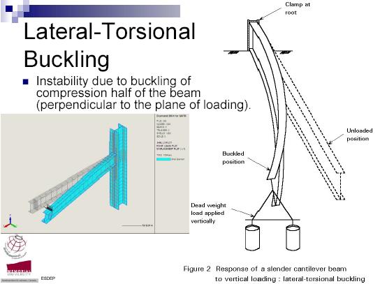
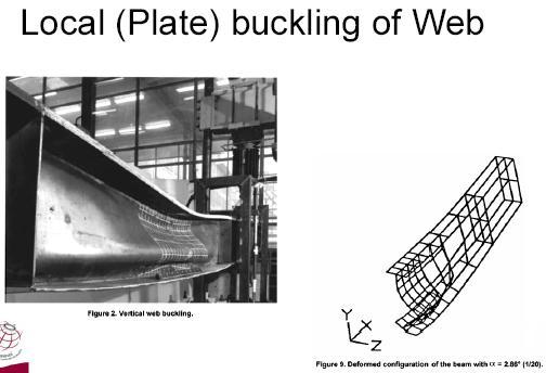
3 2. They should be proportioned for stiffness, keeping in mind their deflections and deformations under service conditions. 3. They should be proportioned for economy, paying attention to the size and grade of steel to yield the most economical design. Beam design consists merely of the provision of adequate bending and shear resistance. For optimum bending resistance, as much of the beams material as possible should be displaced as far as practicable from the neutral axis. The web area should be sufficient to resist shear. Maximum moment and maximum shear usually occur at different sections. Though simple in design, the lateral buckling of beam as a whole, or of its compression flange or its web pose complications. Another problem is of proper depth an increase in depth may be desirable for moment resistance, it may at the same impair resistance to lateral or web buckling (Figure).
4


5 TYPES OF BEAMS: Beams are generally classified according to their geometry and the manner in which they are supported. They may be straight or curved. Figure: Straight Beam


6 Figure: Curved Beam Girders usually the most important beams which are frequently at wide spacing. Joists usually less important beams which are closely spaced, frequently with truss type webs. Stringers- Longitudinal beams spanning between floor beams. Purlins- Roof beams spanning between trusses Girts- horizontal wall beams serving principally to resist bending due to wind on the side of an industrial building. Lintels- Members supporting a wall over window or door openings.
7
8
9

10
11
12
13
14 Design of eccentric connection, framed, stiffened and seat connection. 1. Determine the safe load P that can be carried by the joint shown in Figure. The bolts used are 20 mm diameter of grade 4.6. The thickness of the Flange of I-section is 9.1 mm and that of bracket plate 10 mm. [ 5 Marks] 40 mm 80mm 80mm 80mm 80mm 40mm P 200 mm A A F 2 θ r n θ F 1 A 60 mm (b) 160 mm 120 mm (a) Solution: For Fe 410 grade of steel: f u = 410 MPa For bolts of grade 4.6: f ub = 400 MPa Partial safety factor for the material of bolt: γ mb =1.25 A nb = stress area of 20 mm diameter bolt = 0.78 x x 20 2 /4 = 245 mm 2 Given: diameter of bolt, d = 20 mm; pitch, p = 80 mm; edge distance, e = 40 mm (2 x20 mm), d 0 = = 22 mm. Strength of bolt in single shear, V dsb = A nb
15 = 245 x Strength of bolt in bearing, V dpb = 2.5 k b dt K b is least of = = 0.606; =0.975; and 1.0 Hence K b = V dpb = 2.5 k b dt = 2.5 x x 20x 9.1 x Hence strength of bolt is V sd = kn Let, P 1 be the factored load. Service load, P = = The bolt which is stressed maximum at A (see Figure) Total number of bolts in the joint, n = 10 The force direct force, F 1 = The force in the bolt due to torque, F 2 = r n = = mm = 4 x [( ) + ( )] + 2 x 60 2 = 164,000 mm 2 F 2 =( )/(164,000 )= P 1
16 430 mm mm COURTESY IARE Cosθ = = The resultant force on the bolt should be less than or equal to the strength of bolt Implies P 1 = kn The service load, P = = kn 2. Design a bracket connection to transfer an end reaction of 225 kn due to factored loads as in Figure below. The end reaction from the girder acts at an eccentricity of 300 mm from the face of the column flange. Design bolted joint connecting the Tee-flange with the column flange. Steel is of grade Fe 410 and bolts of grade 4.6. [ 5 Marks] [ Page No. 721, S.K. Duggal 2 nd edition] A 225 kn 300 mm 470 mm Tee bracket mm A
17 Solution: For Fe 410 grade of steel: f u = 410 Mpa For bolts of grade 4.6: f ub = 400 MPa Partial safety factor for the material bolt: γ mb = 1.25 The bolts along section AA are subjected to (i) Shear due to the load, P = 225kN passing through the c.g. of the joint (ii) Tension due to bending moment, M = 225 x 300 = 67,500 knmm Let us provide 24 mm diameter bolts for making the connection. For 24 mm diameter bolts Stress area, A nb = 353 mm 2 [( x 24 2 x0.78)/4] Minimum pitch, p = 2.5 x 24 = 60 mm 65 mm Edge distance = 1.5 x (24+2) = 39 mm 40 mm Strength of the bolt in single shear, Vdsb = Vsd = A nb = 353 x = kn Strength of bolts in tension T db = T nb /γ mb T nb = 0.9 f ub A nb = 0.9 x 400 x 353 x10-3 = kn f yb = 250 x = kn Hence, T db = T nb /γ mb = / 1.25 = kn The bolts will be provided in two vertical rows, one on each side of the web of the Tee section, connecting the flanges of the two sections.
18 Number of bolts required in one row, n = = = Hence provide 7 bolts in each row at a pitch of 65 mm and edge distance of 40 mm. Total depth of the bracket plate = 6 x x 40 = 470 mm h = = 430 mm The neutral axis is assumed to lie at h/7 from the bottom of the bracket, i.e., at 430/7 = mm = 2 x [( ) + ( ) + ( ) + ( ) ) +( )] = mm = 2 x [ ]= 657,502.6 mm 2 M = = = x 10 3 knm Tensile force in the critical bolt, T b = = = kn (y n = mm) Shear force in the critical bolt, V sb = = Check
19 = Which is as it should be. 3. An ISLB N/m transmits an end reaction of 385 kn, under factored loads, to the web of ISMB N/m. Design a bolted framed connection. Steel is of grade Fe410 and bolts are of grade 4.6. [5 Marks] (L.Date 25/03/2015) Solution: For Fe 410 grade of steel: f u = 410 MPa, f y = 250 MPa For bolts of grade 4.6: f ub = 400 MPa Partial safety factor for material of bolt, γ mb = 1.25 Partial safety factor for material, γ m0 = 1.10 The relevant properties of the sections from Steel Tables are: Property ISLB 300 ISMB 450 Depth of section, h 300 mm 450 mm Width of flange, bf 150 mm 150 mm Thickness of flange,tf 9.4 mm 17.4 mm Thickness of web, tw 6.7 mm 9.4 mm Gauge, g 90 mm 90 mm Note down this Figure
20 ISMB 450 ISLB 300 Connection of web of ISLB 300 with framing angle leg Let us provide 24 mm diameter bolts. The bolts will be in double shear. Assuming the aggregate thickness of the angle legs to be more than the thickness of web, the bolts will bear on the web of ISLB 300. For 24 mm diameter bolt, Stress area, A nb = 353 mm 2 Minimum pitch, p = 2.5 x 24 = 60 mm ==65 mm Edge distance, e = 39 mm == 40 mm Diameter of bolt hole, d 0 = = 26 mm Strength of bolt in double shear, V dsb = 2 x A nb = 2 x 353 x kn Strength of bolt in bearing, V dpb = 2.5 Kb dt K b is least of = = 0.513;
21 Hence K b = =0.975; and 1.0 V dpb = 2.5 x x 24 x 6.7 x (410/1.25) x 10-3 = kn Hence strength of the bolt = kn Number of bolts required for making the connection, n = 385 / = Two framing angles, one on each side of the web will be provided. Provide the bolts in two vertical rows. Minimum size of angle leg = 2 x = 145 mm 150 mm Connection of web of ISMB 450 with framing angle leg Let us provide 24 mm diameter bolts. The bolts will be in single shear. Assuming the thickness of angle leg to be more than the thickness of web of ISMB450, the bolts will bear on web of ISMB 450. Strength of bolt in single shear, V dsb = A nb = 353 x = kn Strength of bolt in bearing, V dpb =2.5 K b dt = 2.5 x x 24 x 9.4 x (410/1.25) x 10-3 = kn Hence, strength of the bolt = kn Number of bolts for making the connection, n = 385 / =
22 Provide 3 bolts each on the legs of the two framing angles as shown in the above Figure. Minimum size of angle leg = 2 x 40 = 80 mm 115 mm Minimum depth of framing angle leg, h = 2 x x65 = 210 mm The thickness of the angle section can be determined by equating the shear force (end reaction) to the shear capacity of the angle leg. V = V d = h(2t w ) (Since there are two angles) 385 x 10 3 = t w = 6.98 mm 10 mm Hence, provide 2 framing angles 150 x 115 x 10 mm in size. 4. Design a stiffened seat connection for an ISMB 350@ 514 N/m transmitting an end reaction of 320 kn (due to factored loads) to a column section ISHB N/m. The steel is of grade Fe 410 and bolts of grade 4.6. [5 Mark s] Solution: For Fe 410 grade of steel: f u = 410 Mpa, f yw = 250 Mpa For bolts of grade 4.6: f ub = 400 Mpa Partial safety factor for material of bolt: γ mb = 1.25 Partial safety factor for material: γ m0 = 1.10 Yield stress ratio, ε = = = 1.0 The relevant properties of the sections to be connected from steel tables are:
23 280 mm COURTESY IARE Property ISMB 350 ISHB 300 Width of flange, b f 140 mm 250 mm Thickness of flange,t f 14.2 mm 10.6 mm Thickness of web, t w 8.1 mm 7.6 mm Gauge, g 80 mm Radius at the root, R 1 14 mm The length of seat angle, B = width of beam flange = 140 mm, (b f = 140 mm) Bearing length of seat leg, b = = mm. Provide a clearance c of 5 mm between the beam and the column flange. Required length of outstanding leg = = mm 200 mm Let us provide seat angle 200 x 150 x 10 mm with seat leg of 200 mm connected to the flange of beam with 2, 24 mm diameter bolts of grade mm mm A A ISA 200 X 150 X 10 mm (Seat angle) mm mm 2, ISA 90 X 60 X 8 mm (Stiffner angle) 60 mm 40 mm Flange of ISHB 300 Radius at root of angle, Ra = 13.5 mm (From steel Tables)
24 Stiffener angles Bearing area required by stiffener angles, A = R = 320 x 10 3 x (1.1/250) = 1408 mm 2 Let us provide two angles ISA 90 x 60 x 8 mm Area provided by the stiffening legs of the angles = 2 x (90 x8) = 1440 mm 2 Length of outstanding leg = 90 8 = 82 mm Thickness of the angle, t a = 8 mm should be more than t w i.e. (8.1 mm) Since the thickness is almost same and stiffener angle section may be used. Length of outstand of stiffener 14 t a ε, i.e., 14 x 8 x 1 = 112 mm (ε = 1) which is as it should be. Distance of end reaction from column flange, e x = 200/2 = 100 mm Stiffener angles provide some rigidity to the seat angle and the reaction is assumed to act at the middle of the seat leg. Thus, the eccentricity is increased. Design of connections Let us provide 24 mm diameter bolts of grade 4.6, at a pitch of 60 mm. The bolts connecting the legs of stiffener angles with column flange will be in single shear and bearing. For 24 mm diameter bolt, A nb = 353 mm 2 Minimum pitch, p = 2.5 x 24 = 60 mm Edge distance, e = 39 mm 40 mm Diameter of bolt hole, d 0 = = 26 mm Strength of the bolt in single shear,
25 V dsb = A nb = 353 x = kn Strength of bolt in bearing, V dpb = 2.5 kb dt K b is least of = = 0.513; Hence K b = =0.975; and 1.0 V dpb = 2.5 x x 24 x 8 x (410/1.25) x 10-3 = kn Hence strength of the bolt = kn There will be two vertical rows of bolts connecting legs of the two stiffener angles with the column flange. Number of bolts in one row, n = = = The depth of stiffener angle = 4 x60 + 2x40 = 320 mm H= = 280 mm h/7 = 280/7 = 40 mm (refer Figure above) The critical bolt will be A. = 2 x [ ] = 1200 mm = 2 x [ ]= mm 2
26 Moment shared by the critical bolt, M = = = x 10 3 knmm Tensile force in the critical bolt, T b = = = kn (y n = 240 mm) Shear force in the critical bolt, V sb = = Check Strength of bolt in tension, T db = T nb /γ mb T nb = 0.9 f ub A nb = 0.9 x 400 x 353 x10-3 = kn f yb = 250 x = kn Hence, T nb = kn and, T db = T nb /γ mb = / 1.25 = kn and + =0.333 Which is it should be.
27 25. When the seated beam connections are preferred and name the types? Answer: When a beam is connected to the flange (or the web) of a steel stanchion, the width of the flange (or the depth of the web) may be insufficient to accommodate the connecting angles, in such cases framed connection is not suitable and seated connection is preferred. 27. What is stiffened seat connection? Answer: In addition to the seat angle, a web cleat is provided when the beam is connected to a beam and a flange cleat is used when the beam is connected to a stanchion. The angle cleats are essential because they keep the beam stable in a vertical position and prevent it from lateral buckling. In the stiffened seat connection, a T-section built-up of two plates is used. (Pag698) Design of Plate Girders 1. Design a welded plate girder 24 m in span and laterally restrained throughout. It has to support a uniform load of 100 kn/m throughout the span exclusive of self-weight. Design the girder without intermediate transverse stiffeners. The steel for the flange and web plates is of grade Fe 410. Yield stress of steel may be assumed to be 250 MPa
28 irrespective of the thickness of plates used. Design the cross section, the end load bearing stiffener and connections. Solution: For Fe 410 grade of steel: f u = 410 MPa, f y = f yp = f yw = 250 Mpa μ= 0.3 E = 2 x 10 5 MPa Partial safety factors, γ mw = 1.50 ( for site welding) ε = ε w = ε f = = = 1.0 = 1.25 (For shop welding) Design Forces Total superimposed load = 100 kn/m Factored superimposed load = 1.5 x 100 = 150 kn/m Let, self-weight of plate girder = = =144 kn Self-weight of plate-girder per meter length = Factored self weight = 1.5 x 6 = 9 kn/m Total uniform factored load = = 159 kn/m Maximum bending moment = = 11,448 knm = 6 kn/m Maximum shear force = = 1908 kn Design of web
29 Optimum depth of plate girder, d = When intermediate transverse stiffeners are not to be provided; d/t w 200ε i.e., 200 (from serviceability criteria) and 345 ε f 2 i.e., 345 (from flange buckling criteria) Let us assume k = d/t w = 180 Optimum depth of plate girder, d = = mm 1800 mm Optimum web thickness, t w = = mm 12 mm (Thickness provided is more since intermediate transverse stiffeners are not to be provided) Let us try web plate 1800 x 12 mm in size. Design of Flanges =
30 Let us assume that bending moment will be resisted by the flanges and shear by the web. Required area of Flange, A f = = mm 2 Assuming width of flange equal to 0.3 times depth of girder, b f = 0.3 x 1800 = 540 mm 560 mm Thickness of flange, t f = = mm Classification of flanges For the flanges to be classifiable as plastic b/t f 8.4ε (ε is yield stress ratio) The outstand of flange, b = 274 mm < 8.4 (8.4ε = 8.4 x 1 = 8.4) Hence, the flanges are plastic. (β b = 1.0) Check for bending strength The trial section of the plate girder is shown in Figure 1. The plastic section modulus of the section,
31 COURTESY IARE Z pz = 2 b f t f 2 x 560 x 50 x x 10 6 mm 3 Moment Capacity, M d = β b Z pz = 1.0 x x 10 6 x = knm >11448kNm which is safe. Shear capacity of web Let us use simple post-critical method mm fillet weld < 200 (200ε = 200 x 1 =200) 12 and also < (345ε 2 = 345 x 1 = 345) 50 which is all right. Figure 1. Elastic critical shear stress,
32 Transverse Stiffeners will be provided at supports only. Hence, K v =5.35 = N/mm 2 The non-dimensional web slenderness ratio for shear buckling stress, λ w = = = >1.20 Shear stress corresponding to buckling (For λ w >1.20), τ b = = = N/mm 2 Shear force corresponding to web buckling, V cr = dt w τ b = 1800 x 12 x x 10-3 = kn < 1908kN Which is unsafe. Let us revise the web thickness from 12 mm to 16 mm. New values of, λ w, τ b, and V cr will be as follows. = N/mm 2
33 λ w = = = = 1.37 > 1.2 τ b = = = N/mm 2 V cr = dt w τ b = 1800 x 12 x x 10-3 = kn > 1908kN Which is safe. Check for lateral-torsional buckling Since the compression flange of the girder is laterally restrained throughout, the possibility of lateral-torsional buckling is not there and this check is not required. Flange to web connection There will be two weld lengths along the span for each flange to web connection [Figure 1] = = x 10 6 mm 4
34 q w Let us provide weld of size, S = 6 mm KS = 0.7 x 6 = 4.2 mm Strength of shop weld per unit length, F wd = = kn/mm > kn/mm Which is all right. End bearing stiffener Local capacity of the web, F w = (b 1 + n 2 ) t w B1 = 125 mm N2 = 50 x 2.5 = 125 mm F w = ( ) x 16 x = kn < 1908 kn Hence, stiffener will be required. Maximum reaction = 1908 kn
35 Let us try two flat sections, as stiffener, one on each side of web. Maximum width of flat that can be accommodated = = 272 mm Let us provide 16 mm thick flat section. Maximum permissible outstand = 2 x t q ε = 20 x 16 x1 = 224mm Let us try flat section 224 x 16 mm in size [Figure 2] t w 20t w Figure 2 Check for buckling of the stiffener Effective area of stiffener = 2 x 224 x 16 + (2 x 20 x 16) x 16 = mm 2. Moment of Inertia of the stiffener, I x = 2 x =
36 Radius of Gyration, r = = = mm Slenderness ratio, λ = For λ = 14.41, f y = 250 N/mm 2, and buckling curve c, the design compressive stress from Table 8.7, f cd = N/mm 2 Buckling resistance, P d = A e f cd = x x 10-3 = kn >1908 kn Which is safe. Hence, stiffener is safe in compression Check for bearing capacity of the stiffener Since the stiffener will be coped to accommodate the fillet weld of flange plate to the web, the available effective width of stiffener flat for bearing will be lesser than the actual width. Let the stiffener plate be copied by 15 mm [Figure 3] Width available for bearing = = 209 mm Bearing strength of the stiffener, F psd = F c - F w Area of stiffener in contact with flange, A q = 2 F c F w = = kn
37 F psd = = 1900 kn > kn Which is safe. Check for torsional resistance provided by end bearing stiffener The ends of the plate girder must have sufficient torsional resistance from transportation and erection view point. The moment of inertia of the end bearing stiffener at support, I s 0.34 α s D 3 T cf I y = = = x 10 6 mm 4 A = 2 x 560 x x16 = 84,800 mm 2 r y = = = mm Slenderness ratio, λ = = > 100( See section 12.17in S.K. Duggal, 2 nd edition) For L LT > 100, α s = = I s, provided 0.34 I s,provided = > x 10 6 mm 4
38 Which is safe. End-stiffener connection There will two weld lengths along the depth of web on each side of stiffener plates. b s = = 209 mm Tension capacity of one flat, T dn = = Shear per unit length q 1 = Let us provide weld of size, S = 5 mm KS = 0.7 x 5 = 3.5 mm Strength of shop weld per unit length, f wd1 = > kn/mm. Hence provide 5 mm fillet weld to connect the end bearing stiffener with the web plate (Figure 4).
39 Design of Gantry Girder Crane wheel Crab wheels Gantry Girder Crane girder Stepped Column Figure: Typical arrangement of gantry girder on a stepped column 1. What is Gantry Girder and what are the forces that are acting on it? Answer: A Gantry girder having no lateral support in its length, has to withstand vertical loads from the weight of crane, hook load and impact and horizontal loads from crane surge. [Meaning of Surge: To move quickly and forcefully in particular direction]. 2Q. Where the gantry girders are used? Answer: Gantry girders or crane girders carry hand operated or electric over head cranes in industrial buildings such as factories, workshops, steel works, etc., to lift heavy materials,
40 equipment etc., to carry them from one location to the other, within the building. 3Q. What is drag force? Answer: This is caused due to the starting and stopping of the crane bridge moving over the crane rails as the crane moves longitudinally, i.e., in the direction of gantry girders. 4Q. What is the permissible deflection where the electrically overhead cranes operated over 5000 kn. Answer: The maximum vertical deflection for crane girder, under dead and imposed loads shall not exceed L/1000, where L is the span of the crane runway girder. 5Q. Mention some of the requirements of a good joint. Answer: 1. The line of thrust should pass through the C.G. of the rivet group and the rivets should be symmetrically arranged about this line. 2. For a member, the rivets should be so arranged that the area of the member joined is not reduced more than necessary. 3. The number and diameter of rivets should be sufficient to develop the maximum stresses induced in all the members at the connection. 4. Members should be straight and bolts used to draw them together before the rivets are driven.
41 2. In what sense the design of plate girders by elastic method and limit state method is different? [2 marks] 3. What is tension field action in plate girders? [ 2 Marks] 4. How does a plate girder derive post- buckling strength? [ 2 marks] 5. Give the expression for the optimum depth of plate girder. [1 Mark] 6. Design a gantry girder to be used in an industrial building carrying a manually operated overhead travelling crane, for the following data: Crane capacity=200 kn Self weight of the crane girder excluding trolley = 200 kn Self weight of the trolley, electric motor, hook, etc. = 40 kn Approximate minimum approach of the crane hook to the gantry girder = 1.20 m Wheel base = 3.5 m c/c distance between gantry rails =16 m c/c distance between columns (span of gantry girder)= 8 m Self weight of rail section = 300 N/m Diameter of crane wheels = 150 mm Steel is of grade Fe 410. Design also the field welded connection if required. The support bracket connection need not be designed. [5 marks]
42 DESIGN OF TRUSSES 1. June 2014: Design a channel section purlin for a trussed roof from the following data. Span of roof = 12 m Spacing of purlin along slope = 2 m Spacing of truss = 4 m Slope of roof truss = 1 vertical, 2 horizontal Wind load on roof = 800 N/m 2 Vertical loads from roof sheets = 150 N/m 2 June 2013: Design I-section purlin with and without sag bars for a trussed roof from the following data Span of roof = 10 m Spacing of purlin along slope or truss = 25m Spacing of truss = 4 m Slope of roof truss = 1 vertical, 2 horizontal Wind load on roof = 1100 N/m 2 Vertical loads from roof sheets = 150 N/m 2. May 2012: Compute the loads on a steel roof truss to suit the following data, Span of the truss = 12 meters Type of truss = Fan type Roof cover = Galvanised corrugated G.C. sheeting Spacing of roof truss = 4.5 meters Wind pressure = 1.2 kn/m 2 May 2011(SET-1)- Design I-section purlin with and without sag bars for a trussed roof from the following data, Span of roof = 10 m Spacing of purlin along slope or truss = 2.5m Spacing of truss = 4 m
43 Slope of roof truss = 1 vertical, 2 horizontal Wind load on roof = 1100 N/m 2 Vertical loads from roof sheets = 150 N/m 2. May 2011(SET-2) Design a channel section purlin with and without sag bars for a trussed roof from the following data, Span of roof = 12 m Spacing of purlin along slope or truss = 2 m Spacing of truss = 4 m Slope of roof truss = 1 vertical, 2 horizontal Wind load on roof = 1100 N/m 2 Vertical loads from roof sheets = 150 N/m 2. May 2011 (SET-3) )- Design I-section purlin with and without sag bars for a trussed roof from the following data, Span of roof = 15 m Spacing of purlin along slope or truss = 3 m Spacing of truss = 4 m Slope of roof truss = 1 vertical, 2 horizontal Wind load on roof = 1200 N/m 2 Vertical loads from roof sheets = 160 N/m 2. May 2011(SET-4) Design a channel section purlin with and without sag bars for a trussed roof from the following data, Span of roof = 12 m Spacing of purlin along slope or truss = 2 m Spacing of truss = 4 m Slope of roof truss = 1 vertical, 2 horizontal Wind load on roof = 1200 N/m 2 Vertical loads from roof sheets = 160 N/m 2.
44 June 2013: Design I-section purlin with and without sag bars for a trussed roof from the following data, Span of roof = 10 m Spacing of purlin along slope or truss = 2.5m Spacing of truss = 4 m Slope of roof truss = 1 vertical, 2 horizontal Wind load on roof surface normal to roof = 1100 N/m 2 Vertical loads from roof sheets = 150 N/m 2. Solution: Given data, Span of roof = 10 m Spacing of purlin along slope or truss = 2.5m Spacing of truss = 4 m Slope of roof truss = 1 vertical, 2 horizontal Slope θ = ½ Tan θ = ½ θ = tan -1 θ = degrees Sinθ = 0.447
45 Cosθ = Tan θ =0.5 Wind load on roof surface normal to roof = 1100 N/m 2 Vertical load from roof sheets = 150 N/m 2 Calculating the Dead Load (D.L.) Load from roof sheeting = 150 x Spacing of purlin = 150 x 2.5 = 375 N/m 2 Assume self weight = 120 N/m 2 Total dead weight (W DL ) = 495 N/m 2 Calculation of Wind Load Given, Wind Load on roof surface = 1100 N/m 2 Total wind load = (W w.l. ) = 1100 x spacing of purlin = 1100 x N/m 2 (i) Design of I-Section Purlin Without Sag Bars It is assumed that the load combination of (Dead Load + Wind Load) creates greater effect on purlin than that of load combination of (Dead Load + Live Load) Consider the load combination (Dead load + Wind load) for I-section purlin.
46 Dead load + Wind load W D.Wx = Load normal to the slope W w.l. + W D.L. Cosθ = cos(26.565) = N W D.Wy = Load parallel to the slope = W D.L. Sin(26.565) = 495 sin(26.565) = N M xx = = = x 10 3 Nmm M yy = = = x 10 3 Nmm Assume = 6 and σ bt = 0.66 f y = 0.66 x 250 = 165 N/mm 2 E = 2 x 10 5 N/mm 2 Finding the Required Sectional Modulus
47 = = = x 10 3 mm 3 Select ISMB 11.5 kg/m Z xx = 51.5 x 10 3 mm 3 Z yy = 10.9 x 10 3 mm 3 Check for Permissible Stress = = N/mm 2 < 165 N/mm 2 Hence safe. (ii) Design of I-Section with Sag Bar Dead load + Wind load W D.Wx = Load normal to the slope = W w.l. + W D.L. Cosθ = cos(26.565) = N W D.Wy = Load parallel to slope
48 = W D.L. Sin(26.565) = 495 sin(26.565) = N Bending Moment M xx = = = x 10 3 Nmm M yy = = = x 10 3 N-mm Finding the Required Sectional Modulus = = = x 10 3 mm 3 Select ISJB 7.1 kg/m from steel Tables Z xx = 42.9 x 10 3 mm 3 Z yy = 3.7 x 10 3 mm 3 Check for Permissible Stress
49 = = N/mm 2 < 165 N/mm 2 Hence safe. Compute the loads on a steel roof truss to suit the following data, Span of the truss = 12 meters Type of truss = Fan type Roof cover = Galvanised corrugated G.C. sheeting Spacing of roof truss = 4.5 meters Wind pressure = 1.2 kn/m 2 Solution: Given that, Span of the truss, l = 12 m, Spacing of roof truss, S = 4.5 m Wind pressure = 1.2 kn/m2 Pitch of roof truss, P = ¼ (assumed) Let, Slope of roof truss be θ Therefore tanθ = 2p Tanθ = 2 x (¼) Tanθ = ½ θ = tan -1 (1/2)
50 θ = Rise of roof truss, R = ¼ x l = ¼ x 12 = 3 m. Length along the sloping roof, L = L = m Length/panel = 6.708/4 = 1.677m (i) Load at Each Panel (a) Dead Load Assuming, weight of galvanized corrugated iron sheets, W GI = kn/m 2 Weight of Purlins, Wp = kn/m 2 Weight of bracing, W b = kn/m 2 Self weight of roof truss, W s = = = 0.09kN/m 2 Total dead load, W D.L. = W GI +W p + W b + W s = = kn/m 2 Length of panel in plan, L p = cosθ L p = cos(26.565) = m Load acting on each intermediate panel,
51 W 1 = x 4.5 x 1.5 = 2619 kn Load acting at end panel, W 2 = W1/2 = 2.619/2 = KN 1. Give briefly the design steps to be followed in the design of a roof truss. 2. Design a steel roof truss to suit the following data: Span of the truss = 10 m Type of truss = Fan-type Roof cover = Galvanised corrugated (GC) sheeting Materials : Rolled steel angles Spacing of roof trusses = 4.5 m Wind pressure Pd = 1.0 kn/m 2 3. Draw the elevation of the roof truss and the details of joints
Design of Beams (Unit - 8)
") Design of Beams (Unit - 8) Contents Introduction Beam types Lateral stability of beams Factors affecting lateral stability Behaviour of simple and built - up beams in bending (Without vertical stiffeners)
Design of Beams (Unit - 8) Contents Introduction Beam types Lateral stability of beams Factors affecting lateral stability Behaviour of simple and built - up beams in bending (Without vertical stiffeners)
Structural Steelwork Eurocodes Development of A Trans-national Approach
 Structural Steelwork Eurocodes Development of A Trans-national Approach Course: Eurocode Module 7 : Worked Examples Lecture 0 : Simple braced frame Contents: 1. Simple Braced Frame 1.1 Characteristic Loads
PLATE GIRDERS II. Load. Web plate Welds A Longitudinal elevation. Fig. 1 A typical Plate Girder
 16 PLATE GIRDERS II 1.0 INTRODUCTION This chapter describes the current practice for the design of plate girders adopting meaningful simplifications of the equations derived in the chapter on Plate Girders
Design of Steel Structures Prof. Damodar Maity Department of Civil Engineering Indian Institute of Technology, Guwahati
 Design of Steel Structures Prof. Damodar Maity Department of Civil Engineering Indian Institute of Technology, Guwahati Module 7 Gantry Girders and Plate Girders Lecture - 3 Introduction to Plate girders
Structural Steelwork Eurocodes Development of A Trans-national Approach
 Structural Steelwork Eurocodes Development of A Trans-national Approach Course: Eurocode 3 Module 7 : Worked Examples Lecture 20 : Simple braced frame Contents: 1. Simple Braced Frame 1.1 Characteristic
Fundamentals of Structural Design Part of Steel Structures
 Fundamentals of Structural Design Part of Steel Structures Civil Engineering for Bachelors 133FSTD Teacher: Zdeněk Sokol Office number: B619 1 Syllabus of lectures 1. Introduction, history of steel structures,
Sabah Shawkat Cabinet of Structural Engineering Walls carrying vertical loads should be designed as columns. Basically walls are designed in
 Sabah Shawkat Cabinet of Structural Engineering 17 3.6 Shear walls Walls carrying vertical loads should be designed as columns. Basically walls are designed in the same manner as columns, but there are
Design of Steel Structures Dr. Damodar Maity Department of Civil Engineering Indian Institute of Technology, Guwahati
 Design of Steel Structures Dr. Damodar Maity Department of Civil Engineering Indian Institute of Technology, Guwahati Module - 7 Gantry Girders and Plate Girders Lecture - 4 Introduction to Plate Girders
Design of Steel Structures Dr. Damodar Maity Department of Civil Engineering Indian Institute of Technology, Guwahati
 Design of Steel Structures Dr. Damodar Maity Department of Civil Engineering Indian Institute of Technology, Guwahati Module - 6 Flexural Members Lecture 5 Hello today I am going to deliver the lecture
Design of Steel Structures Prof. S.R.Satish Kumar and Prof. A.R.Santha Kumar
 6. BEAMS 6.1 Introduction One of the frequently used structural members is a beam whose main function is to transfer load principally by means of flexural or bending action. In a structural framework,
Karbala University College of Engineering Department of Civil Eng. Lecturer: Dr. Jawad T. Abodi
 Chapter 05 Structural Steel Design According to the AISC Manual 13 th Edition Analysis and Design of Beams By Dr. Jawad Talib Al-Nasrawi University of Karbala Department of Civil Engineering 71 Introduction
QUESTION BANK SEMESTER: III SUBJECT NAME: MECHANICS OF SOLIDS
 QUESTION BANK SEMESTER: III SUBJECT NAME: MECHANICS OF SOLIDS UNIT 1- STRESS AND STRAIN PART A (2 Marks) 1. Define longitudinal strain and lateral strain. 2. State Hooke s law. 3. Define modular ratio,
QUESTION BANK DEPARTMENT: CIVIL SEMESTER: III SUBJECT CODE: CE2201 SUBJECT NAME: MECHANICS OF SOLIDS UNIT 1- STRESS AND STRAIN PART A
 DEPARTMENT: CIVIL SUBJECT CODE: CE2201 QUESTION BANK SEMESTER: III SUBJECT NAME: MECHANICS OF SOLIDS UNIT 1- STRESS AND STRAIN PART A (2 Marks) 1. Define longitudinal strain and lateral strain. 2. State
Job No. Sheet No. Rev. CONSULTING Engineering Calculation Sheet. Member Design - Steel Composite Beam XX 22/09/2016
 CONSULTING Engineering Calculation Sheet jxxx 1 Member Design - Steel Composite Beam XX Introduction Chd. 1 Grade 50 more common than Grade 43 because composite beam stiffness often 3 to 4 times non composite
3 Hours/100 Marks Seat No.
 *17304* 17304 14115 3 Hours/100 Marks Seat No. Instructions : (1) All questions are compulsory. (2) Illustrate your answers with neat sketches wherever necessary. (3) Figures to the right indicate full
Structural Steelwork Eurocodes Development of A Trans-national Approach
 Structural Steelwork Eurocodes Development of A Trans-national Approach Course: Eurocode Module 7 : Worked Examples Lecture 22 : Design of an unbraced sway frame with rigid joints Summary: NOTE This example
Mechanics of Materials Primer
 Mechanics of Materials rimer Notation: A = area (net = with holes, bearing = in contact, etc...) b = total width of material at a horizontal section d = diameter of a hole D = symbol for diameter E = modulus
Unfinished Bolt ordinary, common, rough or black bolts High strength Bolt friction type bolts
 Bolted Connections Introductions: Connections are always needed to connect two members. It is necessary to ensure functionality and compactness of structures. Prime role of connections is to transmit force
Downloaded from Downloaded from / 1
 PURWANCHAL UNIVERSITY III SEMESTER FINAL EXAMINATION-2002 LEVEL : B. E. (Civil) SUBJECT: BEG256CI, Strength of Material Full Marks: 80 TIME: 03:00 hrs Pass marks: 32 Candidates are required to give their
Longitudinal strength standard
 (1989) (Rev. 1 199) (Rev. Nov. 001) Longitudinal strength standard.1 Application This requirement applies only to steel ships of length 90 m and greater in unrestricted service. For ships having one or
Example 4: Design of a Rigid Column Bracket (Bolted)
") Worked Example 4: Design of a Rigid Column Bracket (Bolted) Example 4: Design of a Rigid Column Bracket (Bolted) Page : 1 Example 4: Design of a Rigid Column Bracket (Bolted) Determine the size of the
Worked Example 4: Design of a Rigid Column Bracket (Bolted) Example 4: Design of a Rigid Column Bracket (Bolted) Page : 1 Example 4: Design of a Rigid Column Bracket (Bolted) Determine the size of the
7 STATICALLY DETERMINATE PLANE TRUSSES
 7 STATICALLY DETERMINATE PLANE TRUSSES OBJECTIVES: This chapter starts with the definition of a truss and briefly explains various types of plane truss. The determinancy and stability of a truss also will
Karbala University College of Engineering Department of Civil Eng. Lecturer: Dr. Jawad T. Abodi
 Chapter 04 Structural Steel Design According to the AISC Manual 13 th Edition Analysis and Design of Compression Members By Dr. Jawad Talib Al-Nasrawi University of Karbala Department of Civil Engineering
FLOW CHART FOR DESIGN OF BEAMS
 FLOW CHART FOR DESIGN OF BEAMS Write Known Data Estimate self-weight of the member. a. The self-weight may be taken as 10 percent of the applied dead UDL or dead point load distributed over all the length.
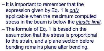
Accordingly, the nominal section strength [resistance] for initiation of yielding is calculated by using Equation C-C3.1.
![Accordingly, the nominal section strength [resistance] for initiation of yielding is calculated by using Equation C-C3.1.](/thumbs/89/98617066.jpg "Accordingly, the nominal section strength [resistance] for initiation of yielding is calculated by using Equation C-C3.1.") C3 Flexural Members C3.1 Bending The nominal flexural strength [moment resistance], Mn, shall be the smallest of the values calculated for the limit states of yielding, lateral-torsional buckling and distortional
C3 Flexural Members C3.1 Bending The nominal flexural strength [moment resistance], Mn, shall be the smallest of the values calculated for the limit states of yielding, lateral-torsional buckling and distortional
KINGS COLLEGE OF ENGINEERING DEPARTMENT OF MECHANICAL ENGINEERING QUESTION BANK. Subject code/name: ME2254/STRENGTH OF MATERIALS Year/Sem:II / IV
 KINGS COLLEGE OF ENGINEERING DEPARTMENT OF MECHANICAL ENGINEERING QUESTION BANK Subject code/name: ME2254/STRENGTH OF MATERIALS Year/Sem:II / IV UNIT I STRESS, STRAIN DEFORMATION OF SOLIDS PART A (2 MARKS)
DESIGN AND DETAILING OF COUNTERFORT RETAINING WALL
 DESIGN AND DETAILING OF COUNTERFORT RETAINING WALL When the height of the retaining wall exceeds about 6 m, the thickness of the stem and heel slab works out to be sufficiently large and the design becomes
SRI CHANDRASEKHARENDRA SARASWATHI VISWA MAHAVIDHYALAYA
 SRI CHANDRASEKHARENDRA SARASWATHI VISWA MAHAVIDHYALAYA (Declared as Deemed-to-be University under Section 3 of the UGC Act, 1956, Vide notification No.F.9.9/92-U-3 dated 26 th May 1993 of the Govt. of
PERIYAR CENTENARY POLYTECHNIC COLLEGE PERIYAR NAGAR - VALLAM THANJAVUR. DEPARTMENT OF MECHANICAL ENGINEERING QUESTION BANK
 PERIYAR CENTENARY POLYTECHNIC COLLEGE PERIYAR NAGAR - VALLAM - 613 403 - THANJAVUR. DEPARTMENT OF MECHANICAL ENGINEERING QUESTION BANK Sub : Strength of Materials Year / Sem: II / III Sub Code : MEB 310
Design of AAC wall panel according to EN 12602
 Design of wall panel according to EN 160 Example 3: Wall panel with wind load 1.1 Issue Design of a wall panel at an industrial building Materials with a compressive strength 3,5, density class 500, welded
BRACING MEMBERS SUMMARY. OBJECTIVES. REFERENCES.
 BRACING MEMBERS SUMMARY. Introduce the bracing member design concepts. Identify column bracing members requirements in terms of strength and stiffness. The assumptions and limitations of lateral bracing
Design of Steel Structures Prof. S.R.Satish Kumar and Prof. A.R.Santha Kumar
 5.4 Beams As stated previousl, the effect of local buckling should invariabl be taken into account in thin walled members, using methods described alread. Laterall stable beams are beams, which do not
Name :. Roll No. :... Invigilator s Signature :.. CS/B.TECH (CE-NEW)/SEM-3/CE-301/ SOLID MECHANICS
/SEM-3/CE-301/ SOLID MECHANICS") Name :. Roll No. :..... Invigilator s Signature :.. 2011 SOLID MECHANICS Time Allotted : 3 Hours Full Marks : 70 The figures in the margin indicate full marks. Candidates are required to give their answers
Name :. Roll No. :..... Invigilator s Signature :.. 2011 SOLID MECHANICS Time Allotted : 3 Hours Full Marks : 70 The figures in the margin indicate full marks. Candidates are required to give their answers
ENG1001 Engineering Design 1
 ENG1001 Engineering Design 1 Structure & Loads Determine forces that act on structures causing it to deform, bend, and stretch Forces push/pull on objects Structures are loaded by: > Dead loads permanent
CHAPTER 5 Statically Determinate Plane Trusses
 CHAPTER 5 Statically Determinate Plane Trusses TYPES OF ROOF TRUSS TYPES OF ROOF TRUSS ROOF TRUSS SETUP ROOF TRUSS SETUP OBJECTIVES To determine the STABILITY and DETERMINACY of plane trusses To analyse
R13. II B. Tech I Semester Regular Examinations, Jan MECHANICS OF SOLIDS (Com. to ME, AME, AE, MTE) PART-A
 PART-A") SET - 1 II B. Tech I Semester Regular Examinations, Jan - 2015 MECHANICS OF SOLIDS (Com. to ME, AME, AE, MTE) Time: 3 hours Max. Marks: 70 Note: 1. Question Paper consists of two parts (Part-A and Part-B)
SET - 1 II B. Tech I Semester Regular Examinations, Jan - 2015 MECHANICS OF SOLIDS (Com. to ME, AME, AE, MTE) Time: 3 hours Max. Marks: 70 Note: 1. Question Paper consists of two parts (Part-A and Part-B)
CHAPTER 5 Statically Determinate Plane Trusses TYPES OF ROOF TRUSS
 CHAPTER 5 Statically Determinate Plane Trusses TYPES OF ROOF TRUSS 1 TYPES OF ROOF TRUSS ROOF TRUSS SETUP 2 ROOF TRUSS SETUP OBJECTIVES To determine the STABILITY and DETERMINACY of plane trusses To analyse
Roadway Grade = m, amsl HWM = Roadway grade dictates elevation of superstructure and not minimum free board requirement.
 Example on Design of Slab Bridge Design Data and Specifications Chapter 5 SUPERSTRUCTURES Superstructure consists of 10m slab, 36m box girder and 10m T-girder all simply supported. Only the design of Slab
NAME: Given Formulae: Law of Cosines: Law of Sines:
 NME: Given Formulae: Law of Cosines: EXM 3 PST PROBLEMS (LESSONS 21 TO 28) 100 points Thursday, November 16, 2017, 7pm to 9:30, Room 200 You are allowed to use a calculator and drawing equipment, only.
 mportant nstructions to examiners: ) The answers should be examined by key words and not as word-to-word as given in the model answer scheme. ) The model answer and the answer written by candidate may
DEPARTMENT OF CIVIL ENGINEERING
 KINGS COLLEGE OF ENGINEERING DEPARTMENT OF CIVIL ENGINEERING SUBJECT: CE 2252 STRENGTH OF MATERIALS UNIT: I ENERGY METHODS 1. Define: Strain Energy When an elastic body is under the action of external
two structural analysis (statics & mechanics) APPLIED ACHITECTURAL STRUCTURES: DR. ANNE NICHOLS SPRING 2017 lecture STRUCTURAL ANALYSIS AND SYSTEMS
 APPLIED ACHITECTURAL STRUCTURES: DR. ANNE NICHOLS SPRING 2017 lecture STRUCTURAL ANALYSIS AND SYSTEMS") APPLIED ACHITECTURAL STRUCTURES: STRUCTURAL ANALYSIS AND SYSTEMS DR. ANNE NICHOLS SPRING 2017 lecture two structural analysis (statics & mechanics) Analysis 1 Structural Requirements strength serviceability
APPLIED ACHITECTURAL STRUCTURES: STRUCTURAL ANALYSIS AND SYSTEMS DR. ANNE NICHOLS SPRING 2017 lecture two structural analysis (statics & mechanics) Analysis 1 Structural Requirements strength serviceability
CHAPTER 4. Stresses in Beams
 CHAPTER 4 Stresses in Beams Problem 1. A rolled steel joint (RSJ) of -section has top and bottom flanges 150 mm 5 mm and web of size 00 mm 1 mm. t is used as a simply supported beam over a span of 4 m
five Mechanics of Materials 1 ARCHITECTURAL STRUCTURES: FORM, BEHAVIOR, AND DESIGN DR. ANNE NICHOLS SUMMER 2017 lecture
 ARCHITECTURAL STRUCTURES: FORM, BEHAVIOR, AND DESIGN DR. ANNE NICHOLS SUMMER 2017 lecture five mechanics www.carttalk.com of materials Mechanics of Materials 1 Mechanics of Materials MECHANICS MATERIALS
UNIT-I STRESS, STRAIN. 1. A Member A B C D is subjected to loading as shown in fig determine the total elongation. Take E= 2 x10 5 N/mm 2
 UNIT-I STRESS, STRAIN 1. A Member A B C D is subjected to loading as shown in fig determine the total elongation. Take E= 2 x10 5 N/mm 2 Young s modulus E= 2 x10 5 N/mm 2 Area1=900mm 2 Area2=400mm 2 Area3=625mm
Influence of residual stresses in the structural behavior of. tubular columns and arches. Nuno Rocha Cima Gomes
 October 2014 Influence of residual stresses in the structural behavior of Abstract tubular columns and arches Nuno Rocha Cima Gomes Instituto Superior Técnico, Universidade de Lisboa, Portugal Contact:
7.3 Design of members subjected to combined forces
 7.3 Design of members subjected to combined forces 7.3.1 General In the previous chapters of Draft IS: 800 LSM version, we have stipulated the codal provisions for determining the stress distribution in
Engineering Science OUTCOME 1 - TUTORIAL 4 COLUMNS
 Unit 2: Unit code: QCF Level: Credit value: 15 Engineering Science L/601/10 OUTCOME 1 - TUTORIAL COLUMNS 1. Be able to determine the behavioural characteristics of elements of static engineering systems
Part 1 is to be completed without notes, beam tables or a calculator. DO NOT turn Part 2 over until you have completed and turned in Part 1.
 NAME CM 3505 Fall 06 Test 2 Part 1 is to be completed without notes, beam tables or a calculator. Part 2 is to be completed after turning in Part 1. DO NOT turn Part 2 over until you have completed and
2. (a) Explain different types of wing structures. (b) Explain the advantages and disadvantages of different materials used for aircraft
 Explain different types of wing structures. (b) Explain the advantages and disadvantages of different materials used for aircraft") Code No: 07A62102 R07 Set No. 2 III B.Tech II Semester Regular/Supplementary Examinations,May 2010 Aerospace Vehicle Structures -II Aeronautical Engineering Time: 3 hours Max Marks: 80 Answer any FIVE
Code No: 07A62102 R07 Set No. 2 III B.Tech II Semester Regular/Supplementary Examinations,May 2010 Aerospace Vehicle Structures -II Aeronautical Engineering Time: 3 hours Max Marks: 80 Answer any FIVE
Design of Steel Structures Prof. S.R.Satish Kumar and Prof. A.R.Santha Kumar
 5.10 Examples 5.10.1 Analysis of effective section under compression To illustrate the evaluation of reduced section properties of a section under axial compression. Section: 00 x 80 x 5 x 4.0 mm Using
COURSE TITLE : APPLIED MECHANICS & STRENGTH OF MATERIALS COURSE CODE : 4017 COURSE CATEGORY : A PERIODS/WEEK : 6 PERIODS/ SEMESTER : 108 CREDITS : 5
 COURSE TITLE : APPLIED MECHANICS & STRENGTH OF MATERIALS COURSE CODE : 4017 COURSE CATEGORY : A PERIODS/WEEK : 6 PERIODS/ SEMESTER : 108 CREDITS : 5 TIME SCHEDULE MODULE TOPICS PERIODS 1 Simple stresses
Special edition paper
 Development of New Aseismatic Structure Using Escalators Kazunori Sasaki* Atsushi Hayashi* Hajime Yoshida** Toru Masuda* Aseismatic reinforcement work is often carried out in parallel with improvement
BPSC Main Exam 2019 ASSISTANT ENGINEER. Test 11. CIVIL ENGINEERING Subjective Paper-I. Detailed Solutions. Detailed Solutions
 etailed Solutions SC Main Exam 19 SSISTNT ENGINEER CIVI ENGINEERING Subjective aper-i Test 11 Q.1 (a) Solution: (i) Calculation of maximum moment at 8 m. For maximum moment Case 1: Case : Case : Case 4:
UNIT 1 STRESS STRAIN AND DEFORMATION OF SOLIDS, STATES OF STRESS 1. Define stress. When an external force acts on a body, it undergoes deformation.
 UNIT 1 STRESS STRAIN AND DEFORMATION OF SOLIDS, STATES OF STRESS 1. Define stress. When an external force acts on a body, it undergoes deformation. At the same time the body resists deformation. The magnitude
D : SOLID MECHANICS. Q. 1 Q. 9 carry one mark each. Q.1 Find the force (in kn) in the member BH of the truss shown.
 in the member BH of the truss shown.") D : SOLID MECHANICS Q. 1 Q. 9 carry one mark each. Q.1 Find the force (in kn) in the member BH of the truss shown. Q.2 Consider the forces of magnitude F acting on the sides of the regular hexagon having
D : SOLID MECHANICS Q. 1 Q. 9 carry one mark each. Q.1 Find the force (in kn) in the member BH of the truss shown. Q.2 Consider the forces of magnitude F acting on the sides of the regular hexagon having
: APPLIED MECHANICS & STRENGTH OF MATERIALS COURSE CODE : 4021 COURSE CATEGORY : A PERIODS/ WEEK : 5 PERIODS/ SEMESTER : 75 CREDIT : 5 TIME SCHEDULE
 COURSE TITLE : APPLIED MECHANICS & STRENGTH OF MATERIALS COURSE CODE : 4021 COURSE CATEGORY : A PERIODS/ WEEK : 5 PERIODS/ SEMESTER : 75 CREDIT : 5 TIME SCHEDULE MODULE TOPIC PERIODS 1 Simple stresses
3. Stability of built-up members in compression
 3. Stability of built-up members in compression 3.1 Definitions Build-up members, made out by coupling two or more simple profiles for obtaining stronger and stiffer section are very common in steel structures,
Unit III Theory of columns. Dr.P.Venkateswara Rao, Associate Professor, Dept. of Civil Engg., SVCE, Sriperumbudir
 Unit III Theory of columns 1 Unit III Theory of Columns References: Punmia B.C.,"Theory of Structures" (SMTS) Vol II, Laxmi Publishing Pvt Ltd, New Delhi 2004. Rattan.S.S., "Strength of Materials", Tata
Design of Reinforced Concrete Structures (II)
") Design of Reinforced Concrete Structures (II) Discussion Eng. Mohammed R. Kuheil Review The thickness of one-way ribbed slabs After finding the value of total load (Dead and live loads), the elements are
Design of Reinforced Concrete Structures (II) Discussion Eng. Mohammed R. Kuheil Review The thickness of one-way ribbed slabs After finding the value of total load (Dead and live loads), the elements are
ENGINEERING SCIENCE H1 OUTCOME 1 - TUTORIAL 4 COLUMNS EDEXCEL HNC/D ENGINEERING SCIENCE LEVEL 4 H1 FORMERLY UNIT 21718P
 ENGINEERING SCIENCE H1 OUTCOME 1 - TUTORIAL COLUMNS EDEXCEL HNC/D ENGINEERING SCIENCE LEVEL H1 FORMERLY UNIT 21718P This material is duplicated in the Mechanical Principles module H2 and those studying
Module 6. Approximate Methods for Indeterminate Structural Analysis. Version 2 CE IIT, Kharagpur
 Module 6 Approximate Methods for Indeterminate Structural Analysis Lesson 35 Indeterminate Trusses and Industrial rames Instructional Objectives: After reading this chapter the student will be able to
Singly Symmetric Combination Section Crane Girder Design Aids. Patrick C. Johnson
 Singly Symmetric Combination Section Crane Girder Design Aids by Patrick C. Johnson PCJohnson@psu.edu The Pennsylvania State University Department of Civil and Environmental Engineering University Park,
DESIGN OF STEEL GRILLAGE FOUNDATION FOR AN AUDITORIUM
 DESIGN OF STEEL GRILLAGE FOUNDATION FOR AN AUDITORIUM Dr.R.Rajesh guna 1, T.Dilipkumar 2, J.Kaleel 3, M.Vidhyalakshmi 4, 1Assistant Professor, Department of Civil Engineering, PERI Institute of Technology,
ME Statics. Structures. Chapter 4
 ME 108 - Statics Structures Chapter 4 Outline Applications Simple truss Method of joints Method of section Germany Tacoma Narrows Bridge http://video.google.com/videoplay?docid=-323172185412005564&q=bruce+lee&pl=true
CHAPTER 6: ULTIMATE LIMIT STATE
 CHAPTER 6: ULTIMATE LIMIT STATE 6.1 GENERAL It shall be in accordance with JSCE Standard Specification (Design), 6.1. The collapse mechanism in statically indeterminate structures shall not be considered.
IVIL.COM, C. English - Arabic. Arrow Assume Assumption Available Average Axes Axial Axis
 Abrupt Action Accuracy Accurate Advantage Algebra Algebraic Algebraic equation English - Arabic Algebraic expression Algebraic sum Allow Allowable Ambiguous Analyze Analysis f sections Structural analysis
INSTITUTE OF AERONAUTICAL ENGINEERING (Autonomous) Dundigal, Hyderabad
 Dundigal, Hyderabad") INSTITUTE OF AERONAUTICAL ENGINEERING (Autonomous) Dundigal, Hyderabad -00 04 CIVIL ENGINEERING QUESTION BANK Course Name : STRENGTH OF MATERIALS II Course Code : A404 Class : II B. Tech II Semester Section
INSTITUTE OF AERONAUTICAL ENGINEERING (Autonomous) Dundigal, Hyderabad -00 04 CIVIL ENGINEERING QUESTION BANK Course Name : STRENGTH OF MATERIALS II Course Code : A404 Class : II B. Tech II Semester Section
SERVICEABILITY OF BEAMS AND ONE-WAY SLABS
 CHAPTER REINFORCED CONCRETE Reinforced Concrete Design A Fundamental Approach - Fifth Edition Fifth Edition SERVICEABILITY OF BEAMS AND ONE-WAY SLABS A. J. Clark School of Engineering Department of Civil
Sub. Code:
 Important Instructions to examiners: ) The answers should be examined by key words and not as word-to-word as given in the model answer scheme. ) The model answer and the answer written by candidate may
JUT!SI I I I TO BE RETURNED AT THE END OF EXAMINATION. THIS PAPER MUST NOT BE REMOVED FROM THE EXAM CENTRE. SURNAME: FIRST NAME: STUDENT NUMBER:
 JUT!SI I I I TO BE RETURNED AT THE END OF EXAMINATION. THIS PAPER MUST NOT BE REMOVED FROM THE EXAM CENTRE. SURNAME: FIRST NAME: STUDENT NUMBER: COURSE: Tutor's name: Tutorial class day & time: SPRING
CHAPTER 4. Design of R C Beams
 CHAPTER 4 Design of R C Beams Learning Objectives Identify the data, formulae and procedures for design of R C beams Design simply-supported and continuous R C beams by integrating the following processes
UNIT- I Thin plate theory, Structural Instability:
 UNIT- I Thin plate theory, Structural Instability: Analysis of thin rectangular plates subject to bending, twisting, distributed transverse load, combined bending and in-plane loading Thin plates having
Failure in Flexure. Introduction to Steel Design, Tensile Steel Members Modes of Failure & Effective Areas
 Introduction to Steel Design, Tensile Steel Members Modes of Failure & Effective Areas MORGAN STATE UNIVERSITY SCHOOL OF ARCHITECTURE AND PLANNING LECTURE VIII Dr. Jason E. Charalambides Failure in Flexure!
Structural Analysis I Chapter 4 - Torsion TORSION
 ORSION orsional stress results from the action of torsional or twisting moments acting about the longitudinal axis of a shaft. he effect of the application of a torsional moment, combined with appropriate
An Increase in Elastic Buckling Strength of Plate Girder by the Influence of Transverse Stiffeners
 GRD Journals- Global Research and Development Journal for Engineering Volume 2 Issue 6 May 2017 ISSN: 2455-5703 An Increase in Elastic Buckling Strength of Plate Girder by the Influence of Transverse Stiffeners
STEEL BUILDINGS IN EUROPE. Multi-Storey Steel Buildings Part 10: Technical Software Specification for Composite Beams
 STEEL BUILDINGS IN EUROPE Multi-Storey Steel Buildings Part 10: Technical Software Specification for Composite Beams Multi-Storey Steel Buildings Part 10: Technical Software Specification for Composite
Tuesday, February 11, Chapter 3. Load and Stress Analysis. Dr. Mohammad Suliman Abuhaiba, PE
 1 Chapter 3 Load and Stress Analysis 2 Chapter Outline Equilibrium & Free-Body Diagrams Shear Force and Bending Moments in Beams Singularity Functions Stress Cartesian Stress Components Mohr s Circle for
SERVICEABILITY LIMIT STATE DESIGN
 CHAPTER 11 SERVICEABILITY LIMIT STATE DESIGN Article 49. Cracking Limit State 49.1 General considerations In the case of verifications relating to Cracking Limit State, the effects of actions comprise
Chapter 7: Bending and Shear in Simple Beams
 Chapter 7: Bending and Shear in Simple Beams Introduction A beam is a long, slender structural member that resists loads that are generally applied transverse (perpendicular) to its longitudinal axis.
MODULE C: COMPRESSION MEMBERS
 MODULE C: COMPRESSION MEMBERS This module of CIE 428 covers the following subjects Column theory Column design per AISC Effective length Torsional and flexural-torsional buckling Built-up members READING:
PES Institute of Technology
 PES Institute of Technology Bangalore south campus, Bangalore-5460100 Department of Mechanical Engineering Faculty name : Madhu M Date: 29/06/2012 SEM : 3 rd A SEC Subject : MECHANICS OF MATERIALS Subject
CH. 5 TRUSSES BASIC PRINCIPLES TRUSS ANALYSIS. Typical depth-to-span ratios range from 1:10 to 1:20. First: determine loads in various members
 CH. 5 TRUSSES BASIC PRINCIPLES Typical depth-to-span ratios range from 1:10 to 1:20 - Flat trusses require less overall depth than pitched trusses Spans: 40-200 Spacing: 10 to 40 on center - Residential
Only for Reference Page 1 of 18
 Only for Reference www.civilpddc2013.weebly.com Page 1 of 18 Seat No.: Enrolment No. GUJARAT TECHNOLOGICAL UNIVERSITY PDDC - SEMESTER II EXAMINATION WINTER 2013 Subject Code: X20603 Date: 26-12-2013 Subject
Studies on Plate Girder with Various Types of Web Plates
 International Journal of Engineering Research and Development e-issn: 2278-067X, p-issn: 2278-800X, www.ijerd.com Volume 6, Issue 2 (March 2013), PP. 14-21 Studies on Plate Girder with Various Types of
Job No. Sheet 1 of 6 Rev B. Made by IR Date Oct Checked by FH/NB Date Oct Revised by MEB Date April 2006
 Job No. Sheet 1 of 6 Rev B, Route de Limours Tel : (0)1 0 85 5 00 Fax : (0)1 0 5 75 8 Revised by MEB Date April 006 DESIGN EXAMPLE 6 BOLTED JOINT A 0 0 angle loaded in tension is to be connected to a gusset
PURE BENDING. If a simply supported beam carries two point loads of 10 kn as shown in the following figure, pure bending occurs at segment BC.
 BENDING STRESS The effect of a bending moment applied to a cross-section of a beam is to induce a state of stress across that section. These stresses are known as bending stresses and they act normally
ε t increases from the compressioncontrolled Figure 9.15: Adjusted interaction diagram
 CHAPTER NINE COLUMNS 4 b. The modified axial strength in compression is reduced to account for accidental eccentricity. The magnitude of axial force evaluated in step (a) is multiplied by 0.80 in case
Appendix J. Example of Proposed Changes
 Appendix J Example of Proposed Changes J.1 Introduction The proposed changes are illustrated with reference to a 200-ft, single span, Washington DOT WF bridge girder with debonded strands and no skew.
Optimum Design of Plate Girder
 IOSR Journal of Mechanical and Civil Engineering (IOSR-JMCE) e-issn: 2278-1684,p-ISSN: 2320-334X, Volume 13, Issue 6 Ver. III (Nov. - Dec. 2016), PP 24-34 www.iosrjournals.org Optimum Design of Plate Girder
National Exams May 2015
 National Exams May 2015 04-BS-6: Mechanics of Materials 3 hours duration Notes: If doubt exists as to the interpretation of any question, the candidate is urged to submit with the answer paper a clear
INFLUENCE OF FLANGE STIFFNESS ON DUCTILITY BEHAVIOUR OF PLATE GIRDER
 International Journal of Civil Structural 6 Environmental And Infrastructure Engineering Research Vol.1, Issue.1 (2011) 1-15 TJPRC Pvt. Ltd.,. INFLUENCE OF FLANGE STIFFNESS ON DUCTILITY BEHAVIOUR OF PLATE
DESIGN OF STORAGE AND MATERIAL HANDLING SYSTEM FOR PIPE INDUSTRY A CASE STUDY
 DESIGN OF STORAGE AND MATERIAL HANDLING SYSTEM FOR PIPE INDUSTRY A CASE STUDY Mr.S.S.Chougule 1, Mr.A.S.Chavan 2, Miss.S.M.Bhujbal 3, Mr.K.S.Falke 4 Prof.R.R.Joshi 5, Prof.M.B.Tandle 6 1,2,3,4 Student,
The subject of this paper is the development of a design
 The erformance and Design Checking of Chord-Angle Legs in Joist Girders THEODORE V. GALAMBOS ABSTRACT The subject of this paper is the development of a design checking method for the capacity of the outstanding
S19 S19. (1997) (Rev ) (Rev. 2 Feb. 1998) (Rev.3 Jun. 1998) (Rev.4 Sept. 2000) (Rev.5 July 2004) S Application and definitions
 (Rev ) (Rev. 2 Feb. 1998) (Rev.3 Jun. 1998) (Rev.4 Sept. 2000) (Rev.5 July 2004) S Application and definitions") (1997) (Rev. 1 1997) (Rev. Feb. 1998) (Rev.3 Jun. 1998) (Rev.4 Sept. 000) (Rev.5 July 004) Evaluation of Scantlings of the Transverse Watertight Corrugated Bulkhead between Cargo Holds Nos. 1 and, with
(1997) (Rev. 1 1997) (Rev. Feb. 1998) (Rev.3 Jun. 1998) (Rev.4 Sept. 000) (Rev.5 July 004) Evaluation of Scantlings of the Transverse Watertight Corrugated Bulkhead between Cargo Holds Nos. 1 and, with
Experimental investigation on monotonic performance of steel curved knee braces for weld-free beam-to-column connections
 Experimental investigation on monotonic performance of steel curved knee braces for weld-free beam-to-column connections *Zeyu Zhou 1) Bo Ye 2) and Yiyi Chen 3) 1), 2), 3) State Key Laboratory of Disaster
D : SOLID MECHANICS. Q. 1 Q. 9 carry one mark each.
 GTE 2016 Q. 1 Q. 9 carry one mark each. D : SOLID MECHNICS Q.1 single degree of freedom vibrating system has mass of 5 kg, stiffness of 500 N/m and damping coefficient of 100 N-s/m. To make the system
Entrance exam Master Course
 - 1 - Guidelines for completion of test: On each page, fill in your name and your application code Each question has four answers while only one answer is correct. o Marked correct answer means 4 points
Mechanics of Structure
 S.Y. Diploma : Sem. III [CE/CS/CR/CV] Mechanics of Structure Time: Hrs.] Prelim Question Paper Solution [Marks : 70 Q.1(a) Attempt any SIX of the following. [1] Q.1(a) Define moment of Inertia. State MI
Chapter Objectives. Design a beam to resist both bendingand shear loads
 Chapter Objectives Design a beam to resist both bendingand shear loads A Bridge Deck under Bending Action Castellated Beams Post-tensioned Concrete Beam Lateral Distortion of a Beam Due to Lateral Load