LIMITED GEOTECHNICAL STUDY TEMPORARY EXCAVATIONS MOORPARK FEEDER UNIT 2 STRENGTHENING PROJECT MOORPARK, CALIFORNIA
|
|
|
- Gyles Moore
- 5 years ago
- Views:
Transcription

1 LIMITED GEOTECHNICAL STUDY TEMPORARY EXCAVATIONS MOORPARK FEEDER UNIT 2 STRENGTHENING PROJECT MOORPARK, CALIFORNIA Prepared for: CALLEGUAS MUNICIPAL WATER DISTRICT July Knoll Drive Ventura, California
2
3 July 2017 TABLE OF CONTENTS Page INTRODUCTION... 1 PROJECT UNDERSTANDING AND STUDY PURPOSE... 1 WORK PERFORMED... 1 FINDINGS... 2 SITE LOCATION... 2 SITE CONDITIONS... 2 Topography... 2 Existing Land Uses... 2 GEOLOGIC CONDITIONS... 3 Regional Settings... 3 Local Geology... 3 Significant Faults... 3 Local Faults... 3 Groundwater Conditions... 4 EARTH MATERIALS... 4 CONCLUSIONS AND RECOMMENDATIONS... 5 GRADING AND EARTHWORK... 5 General... 5 Materials... 5 Site Preparation... 6 Excavation... 6 RECOMMENDATIONS FOR EXCAVATION AND SHORING DESIGN... 7 Introduction... 7 Excavation Design Criteria... 7 LATERAL EARTH PRESSURES FOR SHORING DESIGN... 8 PAVEMENT DESIGN... 8 CLOSURE AND LIMITATIONS... 8 PLATES Site Location Map... 1 Geotechnical Map... 2 N:\PROJECT DATA\2017\ \ LIMITED GEOTECH STUDY REPT.JULY17.DOCX - i -
4 July 2017 TABLE OF CONTENTS (Continued) APPENDICES APPENDIX A: APPENDIX B: SUBSURFACE EXPLORATION LABORATORY TESTING N:\PROJECT DATA\2017\ \ LIMITED GEOTECH STUDY REPT.JULY17.DOCX - ii -
5 July 2017 INTRODUCTION Padre Associates is pleased to submit this report presenting the findings, conclusions, and recommendations developed during our limited geotechnical study for the Moorpark Feeder Unit 2 Project (Project Site), located in Moorpark, California. The Project Site is located along Highway 23, between the New Los Angeles Avenue and Tierra Rejada freeway exits in Ventura County, as shown on Plate 1 - Site Location Map. The following sections present our project understanding, study purpose, work performed, and our findings, conclusions and recommendations. PROJECT UNDERSTANDING AND STUDY PURPOSE The project consists of the replacement of 10 segments of 42-inch diameter water pipeline. The focus of this limited study is on the three segments located within the Caltrans right-of-way on both the east and west sides of State Route 23 in Moorpark, California. The purpose of our limited geotechnical study is to evaluate subsurface conditions and provide recommendations for excavation and temporary shoring systems, the design of which will be performed by others. The pipeline replacement activities will consist of the temporary excavation of the specific pipeline segments in order to replace those sections of pipe. Excavations may be accomplished with proper sloping of the excavation banks or by the use of temporary shoring systems. This report includes discussions regarding regional and local geologic conditions, descriptions of soil conditions that are likely to be encountered, and recommendations for excavation along lateral earth pressure design values for use in the design of temporary shoring systems. The report also includes hollow-stem-auger (HSA) and hand-auger drill hole logs, results of laboratory testing, maps showing exploration locations, and results of geotechnical analyses. WORK PERFORMED The scope of work for this investigation was developed through a site visit and through conversations with CMWD, and was conducted in general accordance with our proposal dated February 10, Work performed for this study included: Review of historical Caltrans record drawings for state route 23 (SR 23) in the project area and available geologic reports and maps relevant to the site; Marking of exploration locations and notification of Underground Service Alert in an effort to locate underground utilities at the exploration locations; Performing a site walk with CMWD and Caltrans inspectors; Exploration of the site at three locations (east and west of SR 23) within the improvements using a hollow-stem auger drill rig. In addition, three shallow N:\PROJECT DATA\2017\ \ LIMITED GEOTECH STUDY REPT.JULY17.DOCX - 1 -
6 July 2017 (approximately 5 feet deep) hand-auger drill holes were completed as part of the preliminary site assessment (PSI) activities. Hand-held GPS located drill holes and hand-auger locations are shown on Plate 2 - Geotechnical Map. Logs of drill holes are presented in Appendix A - Subsurface Exploration; Laboratory testing of soil samples obtained from selected depth intervals within each exploration. A description of laboratory tests performed and the results of those tests are presented in Appendix B - Laboratory Testing; and Preparation of this report presenting our findings, conclusions, and recommendations. FINDINGS SITE LOCATION The Project Site is located in the City of Moorpark in southern Ventura County, California as shown on Plate 1. The Project Site is adjacent to the north and southbound lanes of SR 23, between New Los Angeles Avenue and Tierra Rejada Road in Caltrans right of way (ROW) that is adjacent to undeveloped parks or privately owned ranches. Latitude and longitude coordinates that were estimated from Google Earth near the center of the Project Site along SR 23 are: Latitude: Longitude: SITE CONDITIONS Topography The Project Site is located on a series of rolling hills with gentle to moderate slopes. Slope gradients range up to greater than 50 percent on the west side of SR 23 and up to approximately 30 percent on the east side of SR 23. Elevations within the Project Site range from about +650 to +700 feet above mean sea level (MSL). Within the area of this project, the site is relatively steep with an elevation change of about 20 feet on the east and 50 feet on the west. In general, the terrain slopes from east to west on the west side of SR 23 and both north to south and west to east on the east side of SR 23. Existing Land Uses The Project Site is located on undeveloped land that is part of Caltrans ROW. The Project Site is bisected by SR 23, with a ranch located on the east side and a municipal park on the west. N:\PROJECT DATA\2017\ \ LIMITED GEOTECH STUDY REPT.JULY17.DOCX - 2 -
7 July 2017 GEOLOGIC CONDITIONS Regional Settings The Project Site is located in the Transverse Range geomorphic/geologic province of Southern California. The Transverse Ranges are composed of Mesozoic- to Cenozoic-age sedimentary, metamorphic and igneous rocks that have been folded or faulted in a general eastwest direction, which is transverse to California's general north-south structural grain. The Transverse Range province is bounded by the San Bernardino Mountains to the east, the Los Angeles basin and Pacific Ocean to the south, Lompoc and the Pacific Ocean to the west, and the Coast Ranges and Mojave provinces to the north. Local Geology The Project Site overlies older Quaternary-aged, non-marine fluviatile sediments of the Saugus Formation that have been deposited to form a weakly consolidated light gray pebble conglomerate and sandstone composed of pebbles and small cobbles. The pebbles are composed of granitic, gneiss, metavolcanic rocks, quartzites, anthrasite, gabbro, and Tertiary volcanic rocks that may have their origin in the Conejo Volcanics. These pebbles are found in soft, sandy matrices that can include minor gray, soft micaceous siltstone to claystone (Dibblee, 1987). Significant Faults The State of California designates faults as active, potentially active, and inactive depending on the recency of the movement that can be substantiated for a fault. A fault is considered active if it can be substantiated that the fault has ruptured during the Holocene (the last 11,000 years). A fault is considered potentially active if it can be substantiated that it has ruptured during the Quaternary (the last 2 million years), but not the Holocene. A fault is considered inactive if it can be substantiated as not having ruptured within the Quaternary. The California Division of Mines and Geology (CDMG) evaluates the activity rating of a fault in fault evaluation reports (FER). FERs compile available geologic and seismologic data and evaluate if a fault should be zoned as active, potentially active, or inactive. If an FER evaluates a fault as active, then it is typically incorporated into a Special Studies Zone in accordance with the Alquist-Priolo Earthquake Hazards Act (AP). If a project is located in an AP Special Studies Zone, it requires site-specific evaluation of fault location and a structure setback if the fault is found to traverse the project site. Our review of the Fault Zone Map, Simi Valley West Quadrangle, on the State of California, Department of Conservation web site indicates that there are currently no AP Special Studies Zones that cross the Project Site (CaDOC, 1999). Local Faults No active faults are known to traverse the Project Site. There is a potentially active fault in the vicinity of the Project Site that has the potential to generate strong ground motion. Local faults consist of the Simi-Santa Rosa fault zone with potentially active segments located N:\PROJECT DATA\2017\ \ LIMITED GEOTECH STUDY REPT.JULY17.DOCX - 3 -
8 July 2017 approximately 3,000 ft southeast of the Project Site and an unnamed inactive fault that is mapped approximately 8,000 ft northwest of the Project Site. Simi-Santa Rosa Fault Zone. The Simi-Santa Rosa fault zone is a regional, potentially active fault system that trends southwest from the northeastern end of Simi Valley to the Oxnard plain. This fault zone has an estimated overall length of about 30 miles. According to Hitchcock et al. (2003), the Simi-Santa Rosa is thought to be a potentially active left oblique reverse fault with a dip of 40 to 80 degrees to the north (USGS, 2000). The Simi-Santa Rosa fault is believed to have an estimated average slip rate of 0.2 to 1 millimeters per year (mm/yr) and a maximum moment magnitude (Mw) earthquake of 7 (Hitchcock et al, 2003 and USGS, 2000). Groundwater Conditions Groundwater was not encountered within the drill holes advanced for this study to depths of approximately 26.5 feet below ground surface (ft bgs). The Ventura County Watershed Protection District (VCWPD) reports in their 2015 Annual Report of Groundwater Conditions that the depth to water bearing materials in the Tierra Rejada Valley Basin varies between 20 to 80 ft bgs. The Project Site is located within the heart of the Tierra Rejada Valley Basin; therefore, even though groundwater was not encountered in this field investigation, groundwater should expect to be encountered between depths of 20 to 80 ft bgs based on the VCWPD annual report. The level of groundwater varies throughout the year, and from year to year. The groundwater conditions discussed herein represent only those conditions encountered at the time and location of our exploration and that previously documented. EARTH MATERIALS For this study, east of SR 23 we advanced and collected soil samples from 2 hollowstem-auger (HSA) drill holes (DH-5 and DH-6) to depths ranging from to 26 to 26.5 ft bgs. The HSA drill holes were advanced within the existing paved access road (DH-5 and DH-6), which has been subject to previous grading and compaction activities. West of SR 23, the third HSA drill hole (DH-1) was met with drilling refusal at 3 ft bgs in the original drill hole location. Two additional attempts were made in the vicinity of that first location (and within the area cleared for utilities) both of which also met refusal at a depth of 3 ft bgs. Due to refusal in all three attempts of DH-1, no samples were collected. Three shallow hand-auger holes (DH-2, DH-3, and DH-4) were also advanced to depths ranging from 3.5 to 5.5 ft bgs in the project area west of SR 23 on the slope approximately 20 ft below the pavement elevation. The hand-auger locations were performed on steep hillsides with unaltered terrain. Approximate drill hole and hand-auger locations are indicated on Plate 2. Earth materials encountered in the drill holes are described below. Artificial Fill (af). Artificial fill was encountered in the top 2 to 3 feet of DH-1 (before refusal was met), DH-5, and DH-6. The artificial fill in DH-1 included very dense, dry, silty sand (SM) placed adjacent to the paved shoulder for SR 23 southbound. In DH-5 and DH-6, the N:\PROJECT DATA\2017\ \ LIMITED GEOTECH STUDY REPT.JULY17.DOCX - 4 -
9 July 2017 artificial fill included the existing asphalt pavement underlain primarily by a sandy road base material. Saugus Formation (Qts). The Saugus Formation was encountered below the artificial fill in the two HSA drill holes (DH-5 and DH-6) that did not meet refusal and in all three of the hand-auger locations (DH-2, DH-3, and DH-4). The Saugus was observed to extend through the bottom of each drill hole with the deepest hole extending 26.5 feet below existing grade. The earth material in the project area is generally comprised of interbedded poorly graded sand (SP), silty sand (SM) with gravel, clayey sand (SC), and sandy lead clay (CL). Locally those materials included sub-angular to sub-rounded pebble sized gravel and angular cobble fragments due to mechanical breaks from drilling. The Saugus Formation was generally dense to very dense and dry to slightly moist. CONCLUSIONS AND RECOMMENDATIONS The geotechnical conditions, as encountered in the three HSA drill holes and three hand auger drill holes advanced for this study, indicate that the Project Site is underlain by moderately dense to very dense granular soils and moderately stiff to stiff fine-grained soils. Practical refusal for the drilling methods used did occur at depths of less than 5 feet at several locations. We are uncertain as to whether the refusal was on a very hard inclusion, geologic bed or man-made feature. We assume the existing pipeline area was previously excavated to construct the pipe and if that is correct the feature(s) that prevented further drilling should not affect the work. No groundwater seepage was encountered in the explorations made during this study, however, groundwater information obtained through VCWPD indicates groundwater may be encountered at depths of 20 to 80 feet below grade in the area of the Project Site. GRADING AND EARTHWORK The geotechnical conditions, as encountered in the drill holes advanced at the Project Site, indicate that the pipeline replacements, as we currently understand it, can be completed provided that the recommendations provided herein are followed. General The following sections provide recommendations for site preparation, fill placement, compaction requirements, and construction of utility trenches and pipe bedding. Also included are anticipated excavation characteristics of the site materials. Materials General Fill. Typically, onsite soils free from organics, debris, deleterious materials, and oversize materials (i.e., over 3 inches in largest dimension) are considered suitable for general fill. Soil types that could be encountered within the anticipated depths of excavation will N:\PROJECT DATA\2017\ \ LIMITED GEOTECH STUDY REPT.JULY17.DOCX - 5 -
10 July 2017 likely consist of silty sand (SM) with lesser amounts of sand (SP/SW), clayey sand (SC) and silty clay (CL). Because the work will take place within the limits previously excavated and backfilled for the existing improvements, we do not anticipate that those materials will all contain significant amounts of cobbles or boulders. The materials encountered may also include imported select backfill placed within the existing pipe zone. General Import Fill. Fill materials imported to the site should be free of organics, trash and debris, deleterious materials, and oversize materials (i.e., over 3 inches in largest dimension). In addition, general imported fill should have an Expansion Index of less than 30, less than 40 percent passing the No. 200 sieve, and a Plasticity Index of less than 10. General imported fill should be observed and, if necessary, tested prior to being brought to the site. Site Preparation Site preparation for the work should initially consist of removal and disposal of existing pavement, debris, vegetation, tree root systems, structures, etc. These materials should be removed to expose earth materials that are free of organics and other deleterious matter. Organic materials should be stripped and removed from the Project Site in areas to be graded. If buried tanks, abandoned wells, or other underground structures are encountered, they should be removed or destroyed in accordance with the requirements of the appropriate regulatory agency. Any resulting excavations should be filled with compacted fill that is placed and compacted in accordance with the project plans and specifications. Incompetent artificial fill materials, as determined by a materials inspector during site grading, should be removed if located within the area of excavation that will affect stability of the excavation. Those artificial fill materials may be screened of organics, deleterious materials, debris, and oversize rocks and used within fill materials placed on site. A materials inspector should observe the artificial fill excavations to confirm that the vertical and lateral extent of those materials have been removed prior to fill placement. Excavation Subsurface data indicates that soil conditions likely to be encountered at within the depth of excavation are generally moderately dense or moderately stiff to stiff. Assuming excavation will take place within the limits of excavation for existing pipe placement, all of the materials encountered are anticipated to be excavated with conventional earth moving equipment (backhoe, excavator, etc.). If excavation extends beyond the limits of the previous excavation, it is possible that isolated areas may expose very dense or rocky (cobble and boulder) conditions and that may result in difficult digging that may require the use of heavier equipment. It should also be noted that excavation may encounter concrete or sack-crete ditch plugs that are commonly placed within linear trench excavation backfill on slopes to prevent the migration of water through trench backfill materials. If variations in subsurface conditions are evident, those variations may affect the recommendations contained in this report. If during excavation and/or scarification, boulders N:\PROJECT DATA\2017\ \ LIMITED GEOTECH STUDY REPT.JULY17.DOCX - 6 -
11 July 2017 and cobbles become dislodged from the native soil matrix, those boulders and cobbles should be removed from the excavation and the resulting void filled with compacted fill, in accordance with the project plans and specifications. Trenches greater than 4 feet deep should be braced and shored in accordance with good construction practice and all applicable safety ordinances. Where shoring is not used, we anticipate that some sloughing will occur if sidewalls are constructed steeper than a 1:1 slope. The actual construction of the trench walls and worker safety is the responsibility of the contractor. RECOMMENDATIONS FOR EXCAVATION AND SHORING DESIGN Introduction Excavations required to perform the pipe replacement project may be made using either sloped excavation techniques or shored excavation. Based on information contained on plans prepared by Perliter & Ingalsbe Consulting Engineers, it appears that depth of excavation could be as deep as 15 to 20 feet below existing grades. The actual construction of the trench walls, shoring and worker safety is the responsibility of the contractor. Excavation Design Criteria Open Cut Excavation Design. For planning purposes, subsurface conditions encountered within the drill holes advanced for this project indicate that open cut excavation techniques can be used provided adequate sloping of excavation sidewalls is performed. The presence of clean or slightly silty sand layers encountered at depth in some of the drill holes would require that those layers and all excavation above those layers be sloped at inclinations of 1.5 to 1 (horizontal to vertical) or flatter. Where excavations encounter moderately dense silty or clayey sand or moderately stiff sandy or lean clay, excavations should be sloped at inclinations of 1:1 or flatter. Actual excavation sloping should be determined at the time of excavation by the contractor s Competent Person based on actual soil types and conditions encountered. Structural Shoring Design. Temporary shoring systems should be designed to resist lateral earth pressures considering both static and surcharge loads. Cantilever shoring systems can be designed using active earth pressures. Shoring systems that are braced or are too stiff to allow movement should be designed using at-rest pressures. Shoring designed to support excavation slopes parallel to SR 23 should be designed as braced systems to prevent any slumping of soil below the road. Lateral earth pressures are provided in the following table as an equivalent fluid weight for the noted condition and assuming that the wall backfill is free to drain and no groundwater is present. The tabulated values presented below are based on a soil unit weight of 120 pounds per cubic foot (pcf). N:\PROJECT DATA\2017\ \ LIMITED GEOTECH STUDY REPT.JULY17.DOCX - 7 -
12 July 2017 Lateral Earth Pressures for Shoring Design Earth Pressure Condition Active with native backfill and level backslope Active with native backfill and 2:1 backslope At-rest with native backfill Equivalent Fluid Weight 40 pcf 64 pcf 60 pcf Surcharges. The recommended equivalent fluid weights do not account for surcharge loads acting on the backfill. Traffic surcharges can be estimated as an additional 2 feet of soil cover, equal to a uniform pressure of 75 pounds per square foot. The traffic surcharge can be neglected if the bottom of excavation at the shoring is outside the limits of a 0.5:1 line projected downward from the edge of the pavement. Passive Pressure. Resistance to lateral loads can be provided by the soil passive resistance acting on those portions of the shoring system embedded in the native soil below the depth of excavation disturbance. A passive resistance of 360 pounds per cubic foot, equivalent fluid weight can be used to estimate the lateral load resistance on side of footings. The recommended passive resistance does not account for descending slopes adjacent to shoring. Coefficient of Friction. A coefficient of friction of 0.25 may be used between native soil and metal shoring systems. If shoring will consist of materials other than metal, the shoring design engineer should provide an appropriate friction value. PAVEMENT DESIGN Pavement design was not included within this scope of work. In the event excavations extend through areas of pavement, we recommend that the existing pavement section thickness be matched for purposes of replacement upon completion of work. CLOSURE AND LIMITATIONS This report has been prepared for the exclusive use of the Calleguas Municipal Water District and their agents for specific application to the Moorpark Feeder Unit 2 Strengthening project in Moorpark, California, as shown on Plates 1 and 2. Padre prepared the findings, conclusions, and recommendations presented herein in accordance with generally accepted geotechnical engineering practices at the time and location that this report was prepared. No other warranty, express or implied, is made. Soil and rock materials are typically not homogenous in type, strength, and other geotechnical properties and can vary between points of observation and exploration. In addition, groundwater and soil moisture conditions can vary seasonally and for other reasons. N:\PROJECT DATA\2017\ \ LIMITED GEOTECH STUDY REPT.JULY17.DOCX - 8 -
13 July 2017 Padre does not and cannot have a complete knowledge of the subsurface conditions underlying a site. The conclusions and recommendations presented in this report are based upon the findings at the points of exploration, interpolation and extrapolation of information between and beyond the points of observation, and are subject to confirmation of the conditions revealed by construction. If the construction is relocated, redesigned, or should structural loading be different than anticipated, the recommendations contained within this report should be considered invalid unless the changes are reviewed and our recommendations modified or approved in writing. Findings of this report are valid as of the date of issuance; however, changes in condition of a property can and will occur with the passage of time. Furthermore, changes in applicable or appropriate standards occur whether they result from legislation or advancement in technology. Accordingly, findings of this report may be invalidated wholly or partially by changes outside of our control. This report is subject to our review and remains valid for a period of one year, unless we issue a written opinion of its continued applicability thereafter. Other than assessment and analyses for aerially deposited lead, which was provided in a separate document, the scope of our services did not include any assessment for the presence or absence of any hazardous / toxic substances (including mold) in the soil, groundwater, surface water, or atmosphere, or the presence of any environmentally sensitive habitats or culturally significant areas. Those services can be provided by Padre if there is such a need. -- o -- N:\PROJECT DATA\2017\ \ LIMITED GEOTECH STUDY REPT.JULY17.DOCX - 9 -
14 N:\PROJECT DATA\2017\ \ LIMITED GEOTECH STUDY REPT.JULY17.DOCX PLATES


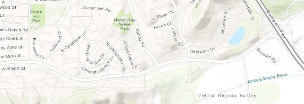
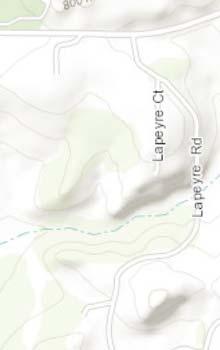
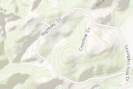
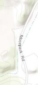
15 Z:\Kristin\GIS Maps\Map Project\CMWD Moorpark Feeder\Report_July2017\Plate 1 Site Location Map.mxd EvonThury 7/13/ ,000 2,000 FEET LEGEND: Project Location Source: Esri Online Basemap, Perliter & Ingalsbe Consulting Engineers Coordinate System: NAD 1983 StatePlane California V FIPS 0405 Feet Notes: This map was created for informational and display purposes only. PROJECT NAME: PROJECT NUMBER: CMWD - MOORPARK FEEDER UNIT 2 STRENGTHENING VENTURA COUNTY, CA DATE: July 2017 MAP EXTENT: VENTURA COUNTY SITE LOCATION MAP PLATE 1
 \" Z:\Kristin\GIS Maps\Map Project\CMWD Moorpark Feeder\Report_July2017\Plate 2 Geotech_DrillHoleLocs.")
16 CalTrans ROW «23 APN: LOCATION 2 & 3 AREA Locked / Gate CalTrans ROW DH-3! > DH-5! >! > DH-4 DH-6! > DH-1b >! DH-1! >! > DH-1a LOCATION 1 AREA DH-2! > APN: ) " Z:\Kristin\GIS Maps\Map Project\CMWD Moorpark Feeder\Report_July2017\Plate 2 Geotech_DrillHoleLocs.mxd EvonThury 7/12/2017 Storm Drains ") CalTrans ROW APN: APN: «23 APN: CalTrans ROW PROJECT LOCATION: LEGEND:! > ADL Soil Assessment Location 0! > Drill Hole Location Parcel Boundary Pipeline Alignment Proposed Access Road FEET PROJECT SITE CMWD - MOORPARK FEEDER UNIT 2 STRENGTHENING VENTURA COUNTY, CA PROJECT NAME: Source:Google EarthPro 10/2016 Image, Per liter & Ingalsbe Consulting Engineers, Ventura County Parcel Data Coordinate System: NAD 1983 StatePlane California V FIPS 0405 Feet ADL = Aerially-Deposited Lead; APN = Assessor Parcel Number; HA = Hand Auger Notes: This map was created for informational and display purposes only. PROJECT NUMBER: DATE: July 2017 PLATE GEOTECHNICAL MAP 2
17 N:\PROJECT DATA\2017\ \ LIMITED GEOTECH STUDY REPT.JULY17.DOCX APPENDIX A SUBSURFACE EXPLORATION
18 July 2017 APPENDIX A SUBSURFACE EXPLORATION The subsurface exploration program for the Moorpark Feeder Unit 2 Project, consisted of the advancement of three hollow-stem-auger drill holes and three hand-auger drill holes. HOLLOW-STEM AUGER DRILL HOLES Three hollow-stem auger drill holes were advanced using a truck-mounted CME 75 drill rig supplied by S/G Drilling Company of Lompoc, California. The drill holes were excavated to depths ranging from 3 to 26.5 feet below existing ground surface. Sampling was performed using a 2-3/8-inch inside diameter Modified California sampler (Cal). The Cal sampler was driven by an above-hole, automatic trip hammer delivering approximately an equivalent amount of driven energy as a 140-pound safety hammer free falling from a height of 30 inches. Bulk samples were recovered from the near-surface drill cuttings. Three shallow hand-auger drill holes were also advanced to depths ranging from 4 to 6 feet below existing ground surface primarily for aerially deposited lead testing. A Padre geologist, using ASTM 2488 for visual soil classification, logged all drill holes. The boundaries between soil types shown on the logs are approximate because of the sampling interval. The logs of the drill holes describe the earth materials encountered, sampling method used, and laboratory tests performed. The logs also show the location, drill hole number, date of drilling, and the names of the logger and drilling subcontractor. A Key to Terms & Symbols Used on Logs is presented on Plate A-1. The logs of the drill holes advanced for this study are presented as Plates A-2.1 through A-2.6. N:\PROJECT DATA\2017\ \ LIMITED GEOTECH STUDY REPT.JULY17.DOCX - A1 -
19 July 2017 ELEVATION, ft DEPTH, ft USCS MATERIAL SYMBOL SAMPLE ID SAMPLE INTERVAL LOCATION: The drill hole location referencing local landmarks or coordinates SURFACE EL: Surface elevation based on MSL MATERIAL DESCRIPTION General Notes All items in legend may not appear on logs. U:\GINT\1-PADRE GINT PROJECTS\ _AERIALLYDEPLEADGEOTECHMOORPARKFEEDERCMWD\ _DRILLHOLES.GPJ 7/5/17 10:45 a, Key Template: PADRE_BORING_LOG_KEY Well graded GRAVEL (GW) Poorly graded GRAVEL (GP) Well graded SAND (SW) Poorly graded SAND (SP) Poorly graded SAND (SP) with gravel Silty SAND (SM) Silty SAND with Gravel (SM) Clayey SAND (SC) Silty, Clayey SAND (SM) Silty, Clayey SAND with Gravel (SM) Elastic SILT (MH) SILT (ML) Clayey SILT (ML) Sandy SILT (ML) Sandy SILT with Gravel (ML) Silty CLAY (CL-ML) Fat CLAY (CH) Sandy Fat CLAY (CH) Sandy Fat CLAY with Gravel (CH) Lean CLAY (CL) Sandy Lean CLAY (CL) Sandy Lean CLAY with Gravel (CL) Peat (PT) Road Base and/or Redrock Oil Spray / Sump Material Asphalt (AC) Metamorphic Rock Basalt C O AR S E G RA I N E D F I N E G RA I N E D O T H E R Sample ID for: Hand-Auger Soil Core Standard Penetration Test (SPT) Environmental Jar Sample Modified California Shelby Tube Bulk or Grab Bag No Recovery NOTES: 1) d/r = driven/recovered 2) ft = feet 3) GP = Geoprobe 4) HA = Hand-Auger 5) HSA/DP = Hollow Stem Auger / Direct Push 6) mg/kg = milligrams per Kilogram 7) MSL = mean sea level 8) NA = not analyzed 9) NM = not measured 10) NR = no recovery 11) p. = pocket penetrometer 12) PID = Photoionization Detector 13) ppm = parts per million 14) SB = Soil Boring 15) t. = torvane 16) TD = Total Depth 17) USCS = Unified Soil Classification System Length of sample symbol approximates recovery length Classification of Soils per ASTM D2487 or D2488 Water Level Symbols Initial or perched water level Final groundwater level Serpentinite Shale KEY TO TERMS & SYMBOLS USED ON LOGS Aerially Deposited Lead /Geotech, Moorpark Feeder Unit 2 Strengthening Project Moorpark, California, California PLATE A-1
20 July 2017 ELEVATION, ft DEPTH, ft USCS MATERIAL SYMBOL SAMPLE ID SAMPLE INTERVAL SAMPLER BLOW COUNT LOCATION: West of Southbound 23 SURFACE ELEVATION: ft +/- (relative datum MSL) NORTHING: EASTING: COORDINATE SYSTEM: NAD83 Ca SP Zn5, ft MATERIAL DESCRIPTION ARTIFICIAL FILL (af) Silty SAND (SM), loose, light olive brown (2.5Y 5/3), dry, fine to medium grained UNIT WET WEIGHT, pcf UNIT DRY WEIGHT, pcf WATER CONTENT, % % PASSING #200 SIEVE LIQUID LIMIT, % PLASTICITY INDEX, % UNDRAINED SHEAR STRENGTH, S u, ksf Very dense, hand-auger refusal Drill bit refusal, attempted two step-outs with the same result U:\GINT\1-PADRE GINT PROJECTS\ _AERIALLYDEPLEADGEOTECHMOORPARKFEEDERCMWD\ _DRILLHOLES.GPJ 7/13/17 11:00 a, Template: PADRE_GEOTECH DRILLING START DATE: June 13, 2017 DRILLING END DATE: June 13, 2017 DEPTH TO GROUNDWATER: Not Encountered COMPLETION DEPTH: 3.0 ft BACKFILLED WITH: Cement Slurry DRILLING/SAMPLING METHOD: H.S.A. HAMMER TYPE: Automatic Trip DRILLING COMPANY: S/G Drilling LOGGED BY: E. von Thury CHECKED BY: J. Damron, P.E., G.E. LOG OF DRILL HOLE DH-1 Aerially Deposited Lead / Geotech, Moorpark Feeder Unit 2 Strengthening Project Moorpark, California Page 1 of 1 The log and data presented are a simplification of actual conditions encountered at the time of drilling at the drilled location. Subsurface conditions may differ at other locations and with the passage of time. Please refer to Key to Boring Log for symbol explanation.
21 U:\GINT\1-PADRE GINT PROJECTS\ _AERIALLYDEPLEADGEOTECHMOORPARKFEEDERCMWD\ _DRILLHOLES.GPJ 7/6/17 12:12 p, Template: PADRE_GEOTECH_HA July 2017 ELEVATION, ft 8DEPTH, ft USCS MATERIAL SYMBOL SAMPLE ID DH-2-0 DH-2-1 DH-2-2 DH-2-3 SAMPLE INTERVAL SAMPLER BLOW COUNT SURFACE ELEVATION: ft +/- (relative datum MSL) NORTHING: EASTING: COORDINATE SYSTEM: NAD83 Ca SP Zn5, ft MATERIAL DESCRIPTION SAUGUS FORMATION (Qts) Silty SAND (SM), loose, light olive brown (2.5Y 5/3), dry, fine to medium grained Sandy SILT (ML), medium dense, olive brown (2.5Y 4/3), moist, fine to medium grained, with some fine gravel and pebbles Hand-auger refusal DRILLING START DATE: June 9, 2017 DRILLING END DATE: June 9, 2017 DEPTH TO GROUNDWATER: Not Encountered COMPLETION DEPTH: 4.0 ft BACKFILLED WITH: Cement Slurry LOCATION: West of Southbound 23 Aerially Deposited Lead (ADL): (mg/kg) UNIT WET WEIGHT, pcf UNIT DRY WEIGHT, pcf WATER CONTENT, % % PASSING #200 SIEVE 7 53 LIQUID LIMIT, % PLASTICITY INDEX, % UNDRAINED SHEAR STRENGTH, S u, ksf DRILLING/SAMPLING METHOD: Hand-Auger HAMMER TYPE: Slide Hammer DRILLING COMPANY: Padre LOGGED BY: M. Ojeda CHECKED BY: J. Damron, P.E., G.E. LOG OF HAND-AUGER DH-2 Aerially Deposited Lead / Geotech, Moorpark Feeder Unit 2 Strengthening Project Moorpark, California Page 1 of 1 The log and data presented are a simplification of actual conditions encountered at the time of drilling at the drilled location. Subsurface conditions may differ at other locations and with the passage of time. Please refer to Key to Boring Log for symbol explanation.
22 U:\GINT\1-PADRE GINT PROJECTS\ _AERIALLYDEPLEADGEOTECHMOORPARKFEEDERCMWD\ _DRILLHOLES.GPJ 7/6/17 12:12 p, Template: PADRE_GEOTECH_HA July 2017 ELEVATION, ft 8DEPTH, ft USCS MATERIAL SYMBOL SAMPLE ID DH-3-0 DH-3-1 DH-3-2 DH-3-3 DH-3-5 SAMPLE INTERVAL SAMPLER BLOW COUNT LOCATION: East of Northbound 23 and CalTrans Access Road SURFACE ELEVATION: ft +/- (relative datum MSL) NORTHING: EASTING: COORDINATE SYSTEM: NAD83 Ca SP Zn5, ft MATERIAL DESCRIPTION SAUGUS FORMATION (Qts) Silty SAND (SM), loose, light olive brown (2.5Y 5/3), dry, fine to medium grained Medium dense, olive brown (2.5Y 4/4), moist, medium grained Total Depth = 5.5 ft DRILLING START DATE: June 9, 2017 DRILLING END DATE: June 9, 2017 DEPTH TO GROUNDWATER: Not Encountered COMPLETION DEPTH: 6.0 ft BACKFILLED WITH: Cement Slurry Aerially Deposited Lead (ADL): (mg/kg) UNIT WET WEIGHT, pcf UNIT DRY WEIGHT, pcf WATER CONTENT, % % PASSING #200 SIEVE LIQUID LIMIT, % PLASTICITY INDEX, % UNDRAINED SHEAR STRENGTH, S u, ksf DRILLING/SAMPLING METHOD: Hand-Auger HAMMER TYPE: Slide Hammer DRILLING COMPANY: Padre LOGGED BY: M. Ojeda CHECKED BY: J. Damron, P.E., G.E. LOG OF HAND-AUGER DH-3 Aerially Deposited Lead / Geotech, Moorpark Feeder Unit 2 Strengthening Project Moorpark, California Page 1 of 1 The log and data presented are a simplification of actual conditions encountered at the time of drilling at the drilled location. Subsurface conditions may differ at other locations and with the passage of time. Please refer to Key to Boring Log for symbol explanation.
23 U:\GINT\1-PADRE GINT PROJECTS\ _AERIALLYDEPLEADGEOTECHMOORPARKFEEDERCMWD\ _DRILLHOLES.GPJ 7/6/17 12:12 p, Template: PADRE_GEOTECH_HA July 2017 ELEVATION, ft 8DEPTH, ft USCS MATERIAL SYMBOL SAMPLE ID DH-4-0 DH-4-1 DH-4-2 DH-4-3 DH-4-5 SAMPLE INTERVAL SAMPLER BLOW COUNT LOCATION: East of Northbound 23 and CalTrans Access Road SURFACE ELEVATION: ft +/- (relative datum MSL) NORTHING: EASTING: COORDINATE SYSTEM: NAD83 Ca SP Zn5, ft MATERIAL DESCRIPTION SAUGUS FORMATION (Qts) Silty SAND (SM), loose, light olive brown (2.5Y 5/3), dry, medium grained Medium dense, light olive brown (2.5Y 5/4), moist Fine grained, subangular to subrounded gravel Total Depth = 5.5 ft DRILLING START DATE: June 9, 2017 DRILLING END DATE: June 9, 2017 DEPTH TO GROUNDWATER: Not Encountered COMPLETION DEPTH: 6.0 ft BACKFILLED WITH: Cement Slurry Aerially Deposited Lead (ADL): (mg/kg) UNIT WET WEIGHT, pcf UNIT DRY WEIGHT, pcf WATER CONTENT, % % PASSING #200 SIEVE LIQUID LIMIT, % PLASTICITY INDEX, % UNDRAINED SHEAR STRENGTH, S u, ksf DRILLING/SAMPLING METHOD: Hand-Auger HAMMER TYPE: Slide Hammer DRILLING COMPANY: Padre LOGGED BY: M. Ojeda CHECKED BY: J. Damron, P.E., G.E. LOG OF HAND-AUGER DH-4 Aerially Deposited Lead / Geotech, Moorpark Feeder Unit 2 Strengthening Project Moorpark, California Page 1 of 1 The log and data presented are a simplification of actual conditions encountered at the time of drilling at the drilled location. Subsurface conditions may differ at other locations and with the passage of time. Please refer to Key to Boring Log for symbol explanation.
24 July 2017 ELEVATION, ft DEPTH, ft 206 USCS MATERIAL SYMBOL SAMPLE ID SAMPLE INTERVAL SAMPLER BLOW COUNT LOCATION: East of Northbound 23 on CalTrans Access Road SURFACE ELEVATION: ft +/- (relative datum MSL) NORTHING: EASTING: COORDINATE SYSTEM: NAD83 Ca SP Zn5, ft MATERIAL DESCRIPTION Asphalt (ac), 3 inches thick Road Base (BASE), UNIT WET WEIGHT, pcf UNIT DRY WEIGHT, pcf WATER CONTENT, % % PASSING #200 SIEVE LIQUID LIMIT, % PLASTICITY INDEX, % UNDRAINED SHEAR STRENGTH, S u, ksf U:\GINT\1-PADRE GINT PROJECTS\ _AERIALLYDEPLEADGEOTECHMOORPARKFEEDERCMWD\ _DRILLHOLES.GPJ 7/13/17 11:00 a, Template: PADRE_GEOTECH Drill rig chatter SAUGUS FORMATION (Qts) Silty SAND with gravel (SM), medium dense, reddish brown (5YR 4/4), dry, fine to medium grained, subangular gravel (0.2 to 1 inch diameter) Angular rock fragments from mechanical break (2 inch diameter), drill rig chatter With some clay Sandy Lean CLAY (CL), dark yellowish brown (10YR 4/6), moist Clayey SAND (SC), very dense, dark yellowish brown (10YR 4/6), slightly moist, fine grained Trace caliche, trace oxidation staining Medium grained DRILLING START DATE: June 13, 2017 DRILLING END DATE: June 13, 2017 DEPTH TO GROUNDWATER: Not Encountered COMPLETION DEPTH: 26.0 ft BACKFILLED WITH: Cement Slurry Poorly graded SAND (SP), medium dense, dark yellowish brown (10YR 4/6), dry, medium grained Sandy Lean CLAY (CL), stiff, strong brown (7.5YR 4/6), slightly moist, fine grained, no to low plasticity DRILLING/SAMPLING METHOD: H.S.A. HAMMER TYPE: Automatic Trip DRILLING COMPANY: S/G Drilling LOGGED BY: E. von Thury CHECKED BY: J. Damron, P.E., G.E. LOG OF DRILL HOLE DH-5 Aerially Deposited Lead / Geotech, Moorpark Feeder Unit 2 Strengthening Project Moorpark, California Page 1 of 2 The log and data presented are a simplification of actual conditions encountered at the time of drilling at the drilled location. Subsurface conditions may differ at other locations and with the passage of time. Please refer to Key to Boring Log for symbol explanation.
25 July 2017 ELEVATION, ft DEPTH, ft 186 USCS MATERIAL SYMBOL SAMPLE ID 5 SAMPLE INTERVAL SAMPLER BLOW COUNT 20 LOCATION: East of Northbound 23 on CalTrans Access Road SURFACE ELEVATION: ft +/- (relative datum MSL) NORTHING: EASTING: COORDINATE SYSTEM: NAD83 Ca SP Zn5, ft MATERIAL DESCRIPTION Poorly graded SAND (SP), medium dense, light olive brown (2.5Y 5/6), dry, fine grained Moist Light yellowish brown (10YR 6/4) UNIT WET WEIGHT, pcf 98 UNIT DRY WEIGHT, pcf 96 WATER CONTENT, % % PASSING #200 SIEVE 2 3 LIQUID LIMIT, % PLASTICITY INDEX, % UNDRAINED SHEAR STRENGTH, S u, ksf NR 50/5" U:\GINT\1-PADRE GINT PROJECTS\ _AERIALLYDEPLEADGEOTECHMOORPARKFEEDERCMWD\ _DRILLHOLES.GPJ 7/13/17 11:00 a, Template: PADRE_GEOTECH Hammer refusal DRILLING START DATE: June 13, 2017 DRILLING END DATE: June 13, 2017 DEPTH TO GROUNDWATER: Not Encountered COMPLETION DEPTH: 26.0 ft BACKFILLED WITH: Cement Slurry DRILLING/SAMPLING METHOD: H.S.A. HAMMER TYPE: Automatic Trip DRILLING COMPANY: S/G Drilling LOGGED BY: E. von Thury CHECKED BY: J. Damron, P.E., G.E. LOG OF DRILL HOLE DH-5 Aerially Deposited Lead / Geotech, Moorpark Feeder Unit 2 Strengthening Project Moorpark, California Page 2 of 2 The log and data presented are a simplification of actual conditions encountered at the time of drilling at the drilled location. Subsurface conditions may differ at other locations and with the passage of time. Please refer to Key to Boring Log for symbol explanation.
26 July 2017 ELEVATION, ft DEPTH, ft USCS MATERIAL SYMBOL SAMPLE ID SAMPLE INTERVAL SAMPLER BLOW COUNT LOCATION: East of Northbound 23 on CalTrans Access Road SURFACE ELEVATION: ft +/- (relative datum MSL) NORTHING: EASTING: COORDINATE SYSTEM: NAD83 Ca SP Zn5, ft MATERIAL DESCRIPTION Asphalt (ac), 3 inches thick Road Base (BASE), UNIT WET WEIGHT, pcf UNIT DRY WEIGHT, pcf WATER CONTENT, % % PASSING #200 SIEVE LIQUID LIMIT, % PLASTICITY INDEX, % UNDRAINED SHEAR STRENGTH, S u, ksf SAUGUS FORMATION (Qts) U:\GINT\1-PADRE GINT PROJECTS\ _AERIALLYDEPLEADGEOTECHMOORPARKFEEDERCMWD\ _DRILLHOLES.GPJ 7/13/17 11:00 a, Template: PADRE_GEOTECH Silty SAND with gravel (SM), dense, dark yellowish brown (10YR 4/6), dry, fine to medium grained, gravel subangular (0.2" to 1" diameter), sampler and waste barrel bent, sampler shoe ripped Drill rig chatter Medium dense, angular gravel (2 inch diameter) With some clay DRILLING START DATE: June 13, 2017 DRILLING END DATE: June 13, 2017 DEPTH TO GROUNDWATER: Not Encountered COMPLETION DEPTH: 26.5 ft BACKFILLED WITH: Cement Slurry Sandy Lean CLAY (CL), stiff, dark yellowish brown (10YR 4/6), slightly moist, fine grained, few caliche, trace oxidation stains Poorly graded SAND (SP), loose, yellowish brown (10YR 5/6), dry, fine grained Clayey SAND (SC), very stiff, strong brown (7.5YR 4/6), slightly moist, fine to medium grained, some caliche, weathered gravel, trace oxidation staining Silty SAND (SM), strong brown (7.5YR 4/6), dry, fine to medium grained DRILLING/SAMPLING METHOD: H.S.A. HAMMER TYPE: Automatic Trip DRILLING COMPANY: S/G Drilling LOGGED BY: E. von Thury CHECKED BY: J. Damron, P.E., G.E. LOG OF DRILL HOLE DH-6 Aerially Deposited Lead / Geotech, Moorpark Feeder Unit 2 Strengthening Project Moorpark, California Page 1 of 2 The log and data presented are a simplification of actual conditions encountered at the time of drilling at the drilled location. Subsurface conditions may differ at other locations and with the passage of time. Please refer to Key to Boring Log for symbol explanation.
27 July 2017 ELEVATION, ft DEPTH, ft USCS MATERIAL SYMBOL SAMPLE ID 5 SAMPLE INTERVAL SAMPLER BLOW COUNT 28 LOCATION: East of Northbound 23 on CalTrans Access Road SURFACE ELEVATION: ft +/- (relative datum MSL) NORTHING: EASTING: COORDINATE SYSTEM: NAD83 Ca SP Zn5, ft MATERIAL DESCRIPTION Clayey SAND (SC), very stiff, black (7.5YR 2.5/1), moist, fine to medium grained, 2 inch thick pocket of organic sandy lean clay Silty SAND with gravel (SM), medium dense, dark yellowish brown (10YR 3/6), slightly moist, fine grained, subangular to subrounded gravel (0.25 to 0.5 inch diameter) Poorly graded SAND (SP), dense, light yellowish brown (2.5Y 6/3), slightly moist, fine grained UNIT WET WEIGHT, pcf UNIT DRY WEIGHT, pcf WATER CONTENT, % % PASSING #200 SIEVE LIQUID LIMIT, % PLASTICITY INDEX, % UNDRAINED SHEAR STRENGTH, S u, ksf U:\GINT\1-PADRE GINT PROJECTS\ _AERIALLYDEPLEADGEOTECHMOORPARKFEEDERCMWD\ _DRILLHOLES.GPJ 7/13/17 11:00 a, Template: PADRE_GEOTECH DRILLING START DATE: June 13, 2017 DRILLING END DATE: June 13, 2017 DEPTH TO GROUNDWATER: Not Encountered COMPLETION DEPTH: 26.5 ft BACKFILLED WITH: Cement Slurry DRILLING/SAMPLING METHOD: H.S.A. HAMMER TYPE: Automatic Trip DRILLING COMPANY: S/G Drilling LOGGED BY: E. von Thury CHECKED BY: J. Damron, P.E., G.E. LOG OF DRILL HOLE DH-6 Aerially Deposited Lead / Geotech, Moorpark Feeder Unit 2 Strengthening Project Moorpark, California Page 2 of 2 The log and data presented are a simplification of actual conditions encountered at the time of drilling at the drilled location. Subsurface conditions may differ at other locations and with the passage of time. Please refer to Key to Boring Log for symbol explanation.
28 N:\PROJECT DATA\2017\ \ LIMITED GEOTECH STUDY REPT.JULY17.DOCX APPENDIX B LABORATORY TESTING
29 July 2017 APPENDIX B LABORATORY TESTING LABORATORY ANALYSES Laboratory tests were performed on selected undisturbed and bulk soil samples to estimate engineering characteristics of the various earth materials encountered. Laboratory testing was performed by Yeh and Associates, Inc., of San Luis Obispo, Cal Poly Corporation GEO-E Laboratory of San Luis Obispo, and NV5 Laboratories, Inc. of Ventura. Testing was performed in accordance with ASTM Standards for Soil Testing, latest revision. The results of laboratory testing are attached. N:\PROJECT DATA\2017\ \ LIMITED GEOTECH STUDY REPT.JULY17.DOCX - B1 -
30
31 DEPARTMENT OF CIVIL AND ENVIRONMENTAL ENGINEERING Atterberg Limits Measurements Test Method: ASTM D4318, D2487 Project Name Tested By Moorpark Feeder Project No ND Testing Date 7/17/2017 SPECIMEN ID AND CLASSIFICATION Boring No. DH 6 Sample No. 3 Depth (ft) 10.5 Soil Description Sandy lean CLAY (CL): red brown, moist LIQUID LIMIT Target Range of Blows Actual Number of Blows Dish ID Mass of Dish (g) Mass of Moist Soil + Dish (g) Mass of Dry Soil + Dish (g) Water Content 33.1% 34.9% 36.7% #DIV/0! PLASTIC LIMIT Dish ID Mass of Dish (g) SUMMARY Mass of Moist Soil + Dish (g) Liquid Limt 36 Mass of Dry Soil + Dish (g) Plastic Limit 15 Water Content 14.8% 14.8% Plasticity Ind % Flow Curve 100 Plasticity Chart 35% 90 % Water Content 30% 25% 20% 15% Plasticity Index CH/OH 10% CL/OL MH/OH 5% 0% Number of Blows 10 0 CL ML ML/OL Liquid Limit
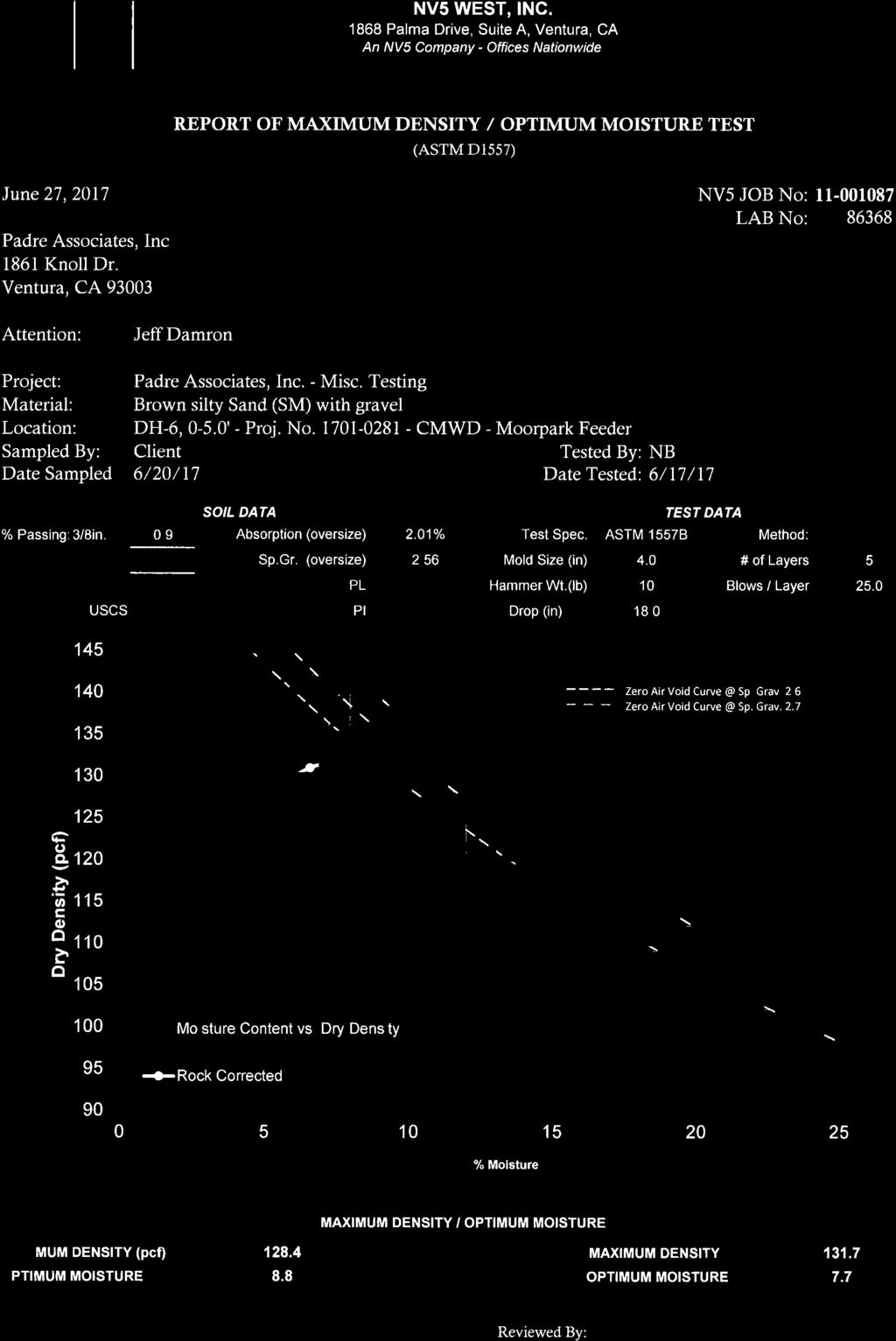
32 Summary of Laboratory Test Results Project No Project Name Moorpark Feeder (Padre Job No ) Date 7/5/2017 Sample Location Gradation Atterberg Corrosion Compaction Boring No. Sample No. Moisture Dry Unit Max. Optimum Gravel Fines < Depth Sample Content Weight R 2 Sand SO > #4 #200 LL PI ph (ohmcm) 4 Cl Unit Water R Value USCS Classification (ft) Type (%) (pcf) (%) (mg/kg) (mg/kg) Weight Content (%) (%) (pcf) (%) DH Grab Sandy SILT (ML) DH Grab Silty SAND (SM) DH MC Sandy CLAY (CL) DH MC Poorly graded SAND (SP) DH MC Silty SAND (SM)
33 Mechnical Sieve Analysis Test Methods: ASTM D6913, D2487, D4718 Project Name Tested By R. Atilano Moorpark Feeder Checked By Project No. J. Cravens Testing Date 6/28/2017 Boring No. Sample No. Depth (ft) Water Content (%) Gravel (%) Sand (%) SUMMARY OF RESULTS Fines (%) D 10 D 30 D 60 C u C c Classification & Soil USCS Description AASHTO Classification DH % 0% 46% 53% Sandy SILT (ML), brown, dry, fine to medium sand -- DH % 0% 97% 3% Poorly graded SAND (SP), yellow, moist, fine sand -- DH % 0% 57% 42% Silty SAND (SM), brown, dry, fine to medium sand -- DH % 3% 44% 53% Sandy CLAY (CL), brown, moist -- DH % 1% 77% 23% Silty SAND (SM), brown, moist, fine sand, with subangular to subrounded gravel --
34 GRADATION CHARTS Boring No.: DH 2 Sample No.: 1 USCS Classification: Sandy SILT (ML) 100% < Gravel > < Sand > < Fines > 3" 2" 1" 3/4" 1/2" 3/8" No. 4 No. 10 No. 20 No. 40 No. 60 No. 100 No % 80% 70% % Passing 60% 50% 40% 30% 20% 10% 0% 100 Boring No.: DH 5 Sample No.: 5 USCS Classification: Poorly graded SAND (SP) 10 1 Particle Diameter (mm) % < Gravel > < Sand > < Fines > 3" 2" 1" 3/4" 1/2" 3/8" No. 4 No. 10 No. 20 No. 40 No. 60 No. 100 No % 80% 70% % Passing 60% 50% 40% 30% 20% 10% 0% Particle Diameter (mm)
35 GRADATION CHARTS Boring No.: DH 6 Sample No.: 4 USCS Classification: Silty SAND (SM) 100% 90% < Gravel > < Sand > < Fines > 3" 2" 1" 3/4" 1/2" 3/8" No. 4 No. 10 No. 20 No. 40 No. 60 No. 100 No % 70% % Passing 60% 50% 40% 30% 20% 10% 0% Particle Diameter (mm) Boring No.: DH 5 Sample No.: 2 USCS Classification: Sandy CLAY (CL) 100% < Gravel > < Sand > < Fines > 3" 2" 1" 3/4" 1/2" 3/8" No. 4 No. 10 No. 20 No. 40 No. 60 No. 100 No % 80% 70% % Passing 60% 50% 40% 30% 20% 10% 0% Particle Diameter (mm)
36 GRADATION CHARTS Boring No.: DH 4 Sample No.: 3 USCS Classification: Silty SAND (SM) 100% < Gravel > < Sand > < Fines > 3" 2" 1" 3/4" 1/2" 3/8" No. 4 No. 10 No. 20 No. 40 No. 60 No. 100 No % 80% 70% % Passing 60% 50% 40% 30% 20% 10% 0% Particle Diameter (mm)
37 6 5 Peak: Φ'= 30, c'= 0.4 ksf Min. Post-Peak 6 5 Sample A Sample B Sample C Shear Stress, ksf SAMPLE ID INITIAL FINAL TEST SUMMARY REMARKS Normal Stress, ksf Boring Number: Sample Number: Sample Depth: USCS Classification: Specimen Water Content, % Dry Unit Weight, pcf Saturation, % Void Ratio Diameter, in Height, in Water Content, % Dry Unit Weight, pcf Void Ratio Displacement at Peak, in Displacement Rate, in/min Normal Stress, ksf Peak Shear Stress, ksf Min. Post-Peak Stress, ksf Test Method: ASTM D Moorpark Feeder DH ft Clayey SAND (SC): yellow to red brown, moist, trace gravel A B C D 9.9% 9.9% 9.9% % 52% 42% % 16.3% 13.4% CLASSIFICATION Horizontal Displacement, in Sieve Size 3/8-in. (9.5mm) # 4 (4.75mm) # 16 (1.18mm) # 30 (0.6mm) # 100 (0.150mm) # 200 (0.075mm) % Passing Atterberg Limits Liquid Limit, % --- Plastic Limit, % --- Plasticity Index, % --- Estimated Gs 2.75 k avg 20ºC, cm/sec --- Vertical Displacement, in DIRECT SHEAR TEST
: red, moist Water Content, % 16.")
 --- Liquid Limit --- # 4 (4.75mm) --- Plastic Limit --- # 16 (1.18mm) --- Plasticity Index --- # 30 (0.6mm) --- Estimated Gs 2.75 # 100 (0.150mm) --- S u from T v, ksf --- # 200 (0.")
38 Confining Stress: 1.2 ksf Interpreted Point of Failure Confining Stress: 1.2 ksf 3.5 Deviator Stress (σ 1 -σ 3 ), ksf Axial Strain, % SAMPLE ID SAMPLE PROPERTIE Boring Number: DH-5 Sample Number: 4 Sample Depth: 15.5 ft USCS Classification: Clayey SAND (SC): red, moist Water Content, % 16.2% Dry Unit Weight, pcf Saturation, % 72% Void Ratio 0.62 Diameter, in 2.42 Height, in 5.00 CLASSIFICATION TEST SUMMARY Sieve Size % Passing Other Parameters 3/8-in. (9.5mm) --- Liquid Limit --- # 4 (4.75mm) --- Plastic Limit --- # 16 (1.18mm) --- Plasticity Index --- # 30 (0.6mm) --- Estimated Gs 2.75 # 100 (0.150mm) --- S u from T v, ksf --- # 200 (0.075mm) --- S u from PP, ksf --- Maximum Deviator Stress, ksf 4.2 Undrained Shear Strength, ksf 2.1 Axial Strain at Failure, % 11.2 Strain Rate, %/min 1.0 Cell Pressure, ksf 1.2 Tested By: ND Date Tested: 7/6/17 SAMPLE IMAGES REMARKS Test Method: ASTM Moorpark Feeder UNCONSOLIDATED UNDRAINED TRIAXIAL TEST
 Project: ITHACA-TOMPKINS REGIONAL AIRPORT EXPANSION Project Location: ITHACA, NY Project Number: 218-34 Key to Soil Symbols and Terms TERMS DESCRIBING CONSISTENCY OR CONDITION COARSE-GRAINED SOILS (major
 Photo 1 - Southerly view across 2700 parking lot toward existing building. Multi-residential building borders western side of property in upper right of view. Photo 2 - Southerly view across 2750 parking
APPENDIX C HYDROGEOLOGIC INVESTIGATION
 Figure B-5.7 Figure B-5.8 Preliminary Geotechnical and Environmental Report Appendix C Hydrogeologic Investigation APPENDIX C HYDROGEOLOGIC INVESTIGATION December 21, 2011 WESTSIDE SUBWAY EXTENSION PROJECT
B-1 BORE LOCATION PLAN. EXHIBIT Drawn By: 115G BROOKS VETERINARY CLINIC CITY BASE LANDING AND GOLIAD ROAD SAN ANTONIO, TEXAS.
 N B-1 SYMBOLS: Exploratory Boring Location Project Mngr: BORE LOCATION PLAN Project No. GK EXHIBIT Drawn By: 115G1063.02 GK Scale: Checked By: 1045 Central Parkway North, Suite 103 San Antonio, Texas 78232
 SOIL CLASSIFICATION CHART COARSE-GRAINED SOILS MORE THAN 50% RETAINED ON NO.200 SIEVE FINE-GRAINED SOILS 50% OR MORE PASSES THE NO.200 SIEVE PRIMARY DIVISIONS GRAVELS MORE THAN 50% OF COARSE FRACTION RETAINED
B-1 SURFACE ELEVATION
 5A 5B LOGGED BY El. S. Bhangoo DRILLING CONTRACTOR Pitcher Drilling DRILLING METHOD Rotary Wash BEGIN DATE 12-14-12 SAMPLER TYPE(S) AND SIZE(S) (ID) SPT, MC BOREHOLE BACKFILL AND COMPLETION COMPLETION
IV. ENVIRONMENTAL IMPACT ANALYSIS G. GEOLOGY AND SOILS
 IV. ENVIRONMENTAL IMPACT ANALYSIS G. GEOLOGY AND SOILS The following section is a summary of the geotechnical report conducted for the proposed project. The Report of Geotechnical Investigation Proposed
Depth (ft) USCS Soil Description TOPSOIL & FOREST DUFF
 USCS Soil Description TOPSOIL & FOREST DUFF") Test Pit No. TP-6 Location: Latitude 47.543003, Longitude -121.980441 Approximate Ground Surface Elevation: 1,132 feet Depth (ft) USCS Soil Description 0 1.5 1.5 5.0 SM 5.0 8.0 SM Loose to medium dense,
Test Pit No. TP-6 Location: Latitude 47.543003, Longitude -121.980441 Approximate Ground Surface Elevation: 1,132 feet Depth (ft) USCS Soil Description 0 1.5 1.5 5.0 SM 5.0 8.0 SM Loose to medium dense,
SUPPLEMENTARY INVESTIGATION AND LABORATORY TESTING Aggregate Resource Evaluation Proposed Bernand Quarry San Diego County, California
 October 3, 2 Mr. Mark San Agustin Project No. 28-- Home Land Investments Document No. -92 2239 Curlew Street San Diego, CA 92 SUBJECT: SUPPLEMENTARY INVESTIGATION AND LABORATORY TESTING Aggregate Resource
Civil Engineering, Surveying and Environmental Consulting WASP0059.ltr.JLS.Mich Ave Bridge Geotech.docx
 2365 Haggerty Road South * Canton, Michigan 48188 P: 734-397-3100 * F: 734-397-3131 * www.manniksmithgroup.com August 29, 2012 Mr. Richard Kent Washtenaw County Parks and Recreation Commission 2330 Platt
December 5, Junction Gateway, LLC 7551 W. Sunset Boulevard #203 Los Angeles, CA Mr. James Frost P: Dear Mr.
 December 5, 2014 Junction Gateway, LLC 7551 W. Sunset Boulevard #203 90046 Attn: Re: Mr. James Frost P: 323.883.1800 Geotechnical Update Letter Sunset & Effie Mixed Use Development 4301 to 4311 Sunset
Geotechnical Data Report
 Geotechnical Data Report Downtown Greenville Future Conveyance Study December 1, 2015 Terracon Project No. 86155032 Prepared for: Prepared by: Terracon Consultants, Inc. December 1, 2015 561 Mauldin Road
APPENDIX A. Borehole Logs Explanation of Terms and Symbols
 APPENDIX A Borehole Logs Explanation of Terms and Symbols Page 153 of 168 EXPLANATION OF TERMS AND SYMBOLS The terms and symbols used on the borehole logs to summarize the results of field investigation
Pierce County Department of Planning and Land Services Development Engineering Section
 Page 1 of 7 Pierce County Department of Planning and Land Services Development Engineering Section PROJECT NAME: DATE: APPLICATION NO.: PCDE NO.: LANDSLIDE HAZARD AREA (LHA) GEOLOGICAL ASSESSMENT REPORT
Northern Colorado Geotech
 PRELIMINARY GEOTECHNICAL ENGINEERING REPORT PROPOSED CECIL FARMS DEVELOPMENT WELD COUNTY ROAD 7, BETWEEN ROADS 7 AND 7 SEVERANCE, COLORADO NORTHERN COLORADO GEOTECH PROJECT NO. 0-6 APRIL 0, 06 Prepared
Field Exploration. March 31, J-U-B ENGINEERS, Inc. 115 Northstar Avenue Twin Falls, Idaho Attn: Mr. Tracy Ahrens, P. E. E:
 March 31, 201 11 Northstar Avenue 83301 Attn: Mr. Tracy Ahrens, P. E. E: taa@jub.com Re: Geotechnical Data Report Preliminary Phase 1 Field Exploration Revision No. 1 Proposed Rapid Infiltration Basin
DATA REPORT GEOTECHNICAL INVESTIGATION GALVESTON CRUISE TERMINAL 2 GALVESTON, TEXAS
 DATA REPORT GEOTECHNICAL INVESTIGATION GALVESTON CRUISE TERMINAL 2 GALVESTON, TEXAS SUBMITTED TO PORT OF GALVESTON 123 ROSENBERG AVENUE, 8TH FLOOR GALVESTON, TEXAS 77553 BY HVJ ASSOCIATES, INC. HOUSTON,
Geotechnical Engineering Report
 Geotechnical Engineering Report Turner Turnpike Widening Bridge B Bridge Crossing: South 257 th West Avenue Creek County, Oklahoma June 1, 2016 Terracon Project No. 04155197 Prepared for: Garver, LLC Tulsa,
APPENDIX A GEOTECHNICAL REPORT
 The City of Winnipeg Bid Opportunity No. 529-2017 Template Version: C420170317 - RW APPENDIX A GEOTECHNICAL REPORT Quality Engineering Valued Relationships KGS Group 2017 Industrial Street Rehabilitation
Limited Geotechnical Engineering Evaluation Classroom Additions Albany County Campus Laramie, Wyoming
 Limited Geotechnical Engineering Evaluation Classroom Additions Albany County Campus 2300 Missile Drive, Cheyenne, Wyoming 82001 Phone 307-635-0222 www.stratageotech.com Limited Geotechnical Engineering
Geotechnical Engineering Report
 Geotechnical Engineering Report Turner Turnpike Widening Polecat Creek Bridge (Bridge A) June 1, 2016 Terracon Project No. 04155197 Prepared for: Garver, LLC Prepared by: Terracon Consultants, Inc. TABLE
 UNIT DESCRIPTIONS: Artificial Fill, Undocumented (Afu): Locally derived sandy silt and silty sand, locally with clay and varying amounts of gravel and man-made debris. Abundant concrete rubble, in places
Geotechnical Investigation Juneau Seawalk - Taku Fisheries to Miner s Wharf Juneau, Alaska DM&A Job No
 Duane Miller & Associates 5821 Arctic Boulevard, Suite A Anchorage, AK 99518-1654 (907) 644-3200 Fax 644-0507 Arctic & Geotechnical Engineering May 4, 2006 Tetra Tech/KCM, Inc. 1971 First Avenue Seattle,
ADDENDUM 1 FISHER SLOUGH RESTORATION PROJECT SKAGIT COUNTY, WASHINGTON
 F I N A L A D D E N D U M 1 R E P O R T ADDENDUM 1 FISHER SLOUGH RESTORATION PROJECT SKAGIT COUNTY, WASHINGTON REPORT OF GEOTECHNICAL INVESTIGATION URS JOB NO. 3376186 Prepared for Tetra Tech Inc. 142
Converse Consultants Geotechnical Engineering, Environmental & Groundwater Science, Inspection & Testing Services
 Converse Consultants Geotechnical Engineering, Environmental & Groundwater Science, Inspection & Testing Services Ms. Rebecca Mitchell Mt. San Antonio College Facilities Planning & Management 1100 North
3.0 SUMMARY OF FINDINGS
 AECOM 500 W Jefferson St. Suite 1600 Louisville, KY 40202 www.aecom.com 502-569-2301 tel 502-569-2304 fax October 17, 2018 Big Rivers Electric Corporation Sebree Generating Station 9000 Highway 2096 Robards,
CITY OF CAPE CORAL NORTH 2 UTILITIES EXTENSION PROJECT CONTRACT 3
 GEOTECHNICAL REPORT CITY OF CAPE CORAL NORTH UTILITIES EXTENSION PROJECT CONTRACT City of Cape Coral Procurement Division Cultural Park Boulevard, nd Floor Cape Coral, FL ISSUED FOR BID VOLUME of GEOTECHNICAL
ATTACHMENT A PRELIMINARY GEOTECHNICAL SUMMARY
 ATTACHMENT A PRELIMINARY GEOTECHNICAL SUMMARY Kevin M. Martin, P.E. KMM Geotechnical Consultants, LLC 7 Marshall Road Hampstead, NH 0384 603-489-6 (p)/ 603-489-8 (f)/78-78-4084(m) kevinmartinpe@aol.com
Parsons APPENDIX A BORING LOGS AND DEVELOPMENT LOG
 Parsons APPENDIX A BORING LOGS AND DEVELOPMENT LOG GEOLOGIC LOG DATE STARTED: DATE COMPLETED: 08-Sep-09 08-Sep-09 LOGGER: Quin Kinnebrew WEATHER: Clear & Warm PAGE 1 OF 2 WELL NO. GMW-66 COMPANY NAME:
APPENDIX C. Borehole Data
 APPENDIX C Borehole Data MAJOR DIVISIONS SOIL CLASSIFICATION CHART SYMBOLS GRAPH LETTER TYPICAL DESCRIPTIONS ADDITIONAL MATERIAL
 R-1 Conveyor Relocation Project Legend 0 500 1000 1500 ft. This map is a user generated static output from an Internet mapping site and is for general reference only. Data layers that appear on this map
GEOTECHNICAL REPORT. Matanuska-Susitna Borough. Parks Highway Connections Museum Drive. Matanuska-Susitna Borough, Alaska.
 Matanuska-Susitna Borough GEOTECHNICAL REPORT Parks Highway Connections Museum Drive Matanuska-Susitna Borough, Alaska March 2, 20 Prepared By: John Thornley, PE Geotechnical Engineer 333 Arctic Blvd.,
Geotechnical Engineering Report
 Geotechnical Engineering Report Turner Turnpike Widening Bridge D Bridge Crossing: South 209 th West Avenue Creek County, Oklahoma June 1, 2016 Terracon Project No. 04155197 Prepared for: Garver, LLC Tulsa,
Appendix G GEOLOGICAL INVESTIGATION
 Appendix G GEOLOGICAL INVESTIGATION JOB NUMBER: 3268.001 DATE: 10-14-13 BY: CC SITE 0 2000 1"=2000' VICINITY MAP CARGILL PARCEL HICKORY STREET AND ENTERPRISE DRIVE NEWARK, CALIFORNIA FOR
Geotechnical Engineering Study, Conifer Senior High School Football Field Improvements, Conifer, Colorado
 2390 South Lipan Street Denver, CO 80223 phone: (303) 742-9700 fax: (303) 742-9666 email: kadenver@kumarusa.com www.kumarusa.com Office Locations: Denver (HQ), Colorado Springs, Fort Collins, and Frisco,
IN SITU SPECIFIC GRAVITY VS GRAIN SIZE: A BETTER METHOD TO ESTIMATE NEW WORK DREDGING PRODUCTION
 IN SITU SPECIFIC GRAVITY VS GRAIN SIZE: A BETTER METHOD TO ESTIMATE NEW WORK DREDGING PRODUCTION Nancy Case O Bourke, PE 1, Gregory L. Hartman, PE 2 and Paul Fuglevand, PE 3 ABSTRACT In-situ specific gravity
ENGINEERING ASSOCIATES
 July 16, 211 Vista Design, Inc. 11634 Worcester Highway Showell, Maryland 21862 Attention: Reference: Dear Mr. Polk: Mr. Richard F. Polk, P.E. Geotechnical Engineering Report Charles County RFP No. 11-9
IV. ENVIRONMENTAL IMPACT ANALYSIS E. GEOLOGY/SOILS
 IV. ENVIRONMENTAL IMPACT ANALYSIS E. GEOLOGY/SOILS Except where otherwise noted, the following Section is based on the Preliminary Geotechnical Investigation, Proposed Medical Office Buildings and Mixed-Use
APPENDIX E SOILS TEST REPORTS
 Otsego County, NY Site Work Specifications APPENDIX E SOILS TEST REPORTS Blue Wing Services, Inc. July 1, 2010 Blue Wing Services May 20, 2010 Page 2 the site, was not made available to Empire at this
 TP-1 N61E 0 DARK BROWN SANDY SILT (ML) stiff, wet with roots (Disturbed Surficial Soil) DEPTH (FEET) 5 REDDISH BROWN SANDSTONE intensely fractured, weak to friable, deeply weathered, tight (Franciscan
Report of Preliminary Geotechnical Exploration. CSO-012 Sewer Separation Cincinnati, Hamilton County, Ohio. February, 2011
 11242843_GeoTech_Preliminary - Feburary 2011_1/40 Report of Preliminary Geotechnical Exploration CSO-012 Sewer Separation Cincinnati, Hamilton County, Ohio February, 2011 11242843_GeoTech_Preliminary -
Geotechnical Data Report
 Geotechnical Data Report ReWa Solar Farm at Durbin Creek Fountain Inn, South Carolina September 1, 2017 Terracon Project No. 86165043 Prepared for: Renewable Water Resources Greenville, South Carolina
IV. ENVIRONMENTAL IMPACT ANALYSIS E. GEOLOGY AND SOILS
 IV. ENVIRONMENTAL IMPACT ANALYSIS E. GEOLOGY AND SOILS The following analysis is based on the Geotechnical Investigation Report, Proposed Mid-Rise Multi- Family Residential Development Project Wetherly
IV. ENVIRONMENTAL IMPACT ANALYSIS E. GEOLOGY AND SOILS
 IV. ENVIRONMENTAL IMPACT ANALYSIS E. GEOLOGY AND SOILS The following section is a summary of the geotechnical report conducted for the Proposed Project. The Geotechnical Engineering Investigation (the
M E M O R A N D U M. Mr. Jonathan K. Thrasher, P.E., Mr. Ian Kinnear, P.E. (FL) PSI
 PSI") M E M O R A N D U M TO: FROM: Mr. Mark Schilling Gulf Interstate Engineering Mr. Jonathan K. Thrasher, P.E., Mr. Ian Kinnear, P.E. (FL) PSI DATE: November 11, 2014 RE: Summary of Findings Geotechnical
M E M O R A N D U M TO: FROM: Mr. Mark Schilling Gulf Interstate Engineering Mr. Jonathan K. Thrasher, P.E., Mr. Ian Kinnear, P.E. (FL) PSI DATE: November 11, 2014 RE: Summary of Findings Geotechnical
IV. ENVIRONMENTAL IMPACT ANALYSIS E. GEOLOGY AND SOILS
 IV. ENVIRONMENTAL IMPACT ANALYSIS E. GEOLOGY AND SOILS INTRODUCTION This section evaluates potential impacts related to geology, including seismicity, and soils associated with development of the proposed
Date: April 2, 2014 Project No.: Prepared For: Mr. Adam Kates CLASSIC COMMUNITIES 1068 E. Meadow Circle Palo Alto, California 94303
 City of Newark - 36120 Ruschin Drive Project Draft Initial Study/Mitigated Negative Declaration Appendix C: Geologic Information FirstCarbon Solutions H:\Client (PN-JN)\4554\45540001\ISMND\45540001 36120
NOA ASSESSMENT HARRIS QUARRY MENDOCINO COUNTY, CALIFORNIA TABLE OF CONTENTS
 NOA ASSESSMENT HARRIS QUARRY MENDOCINO COUNTY, CALIFORNIA TABLE OF CONTENTS Introduction... 1 Scope of Services... 1 Project Location and Description... 1 Geologic Setting... 1 Regional Geology... 1 Site
DRILL HOLE # BH-BGC13-FN-01
 DILL HOLE # BH-BGC3-FN-0 Drill Method: Mud otary/coring Depth To ock (m): N/A Page of 7 eviewed by: AJB 0 GAVEL (GW) Fine to coarse, sandy, well graded, dense, max particle size = 30 mm, angular to subrounded,
June 9, R. D. Cook, P.Eng. Soils Engineer Special Services Western Region PUBLIC WORKS CANADA WESTERN REGION REPORT ON
 PUBLIC WORKS CANADA WESTERN REGION REPORT ON GEOTECHNICAL INVESTIGATION PROPOSED MARTIN RIVER BRIDGE MILE 306.7 MACKENZIE HIGHWAY Submitted by : R. D. Cook, P.Eng. Soils Engineer Special Services Western
Preliminary Geotechnical Evaluation Gooseberry Point Pedestrian Improvements Whatcom County, Washington SITE AND PROJECT DESCRIPTION
 File No. 12-100 Geotechnical & Earthquake Engineering Consultants Mr. Kevin Brown, P.E. Gray & Osborne, Inc. 3710 168 th Street NE, Suite B210 Arlington, Washington 98223 Subject: Draft Report Preliminary
Slope Stability Evaluation Ground Anchor Construction Area White Point Landslide San Pedro District Los Angeles, California.
 Slope Stability Evaluation Ground Anchor Construction Area White Point Landslide San Pedro District Los Angeles, California Submitted To: Mr. Gene Edwards City of Los Angeles Department of Public Works
New WW Hastings Hospital Geotechnical Investigation RFP Addendum #1
 88 E. Marshall Street, Suite 0 Tulsa, OK 76 98 8 9 Phone 98 8 798 FAX DATE: April 9, 0 ADDENDUM NO.: PROJECT: New WW Hastings Hospital BID PACKAGE NO: Geotechnical Investigation RFP SUBMITTED BY: CNCR
Converse Consultants Geotechnical Engineering, Environmental & Groundwater Science, Inspection & Testing Services
 Converse Consultants Geotechnical Engineering, Environmental & Groundwater Science, Inspection & Testing Services July 27, 2017 Ms. Rebecca Mitchell Mt. San Antonio College Facilities Planning & Management
AN EMPLOYEE OWNED COMPANY
 CTL Engineering, Inc. 2860 Fisher Road, P.O. Box 4448, Columbus, Ohio 43204338 Phone: 614/2768123 Fax: 614/2766377 Email: ctl@ctleng.com AN EMPLOYEE OWNED COMPANY Consulting Engineers Testing Inspection
Geotechnical Engineering Report
 Geotechnical Engineering Report Richland Creek Trunk Sewer Greenville, South Carolina March 31, 2014 Terracon Project No. 86145008 Prepared for: Renewable Water Resources Greenville, South Carolina Prepared
Ardaman & Associates, Inc. Geotechnical, Environmental and Materials Consultants
 SUBSURFACE SOIL EXPLORATION 42-INCH FORCE MAIN REPLACEMENT CHIQUITA BOULEVARD S AND SW 34 TH STREET CAPE CORAL, LEE COUNTY, FLORIDA Ardaman & Associates, Inc. Geotechnical, Environmental and Materials
Hydro One (Sept 2014) Hydro One (Sept 2014) Hydro One (Sept 2014)
 Hydro One (Sept 2014) Hydro One (Sept 2014)") TABLE 1 WELL CONSTRUCTION DETAILS MOE WWR No Well ID Location Installation Date Status Easting Coordinates Northing Source Elevation Screened Interval Screened Material Borehole Well Stick-up Ground Top
TABLE 1 WELL CONSTRUCTION DETAILS MOE WWR No Well ID Location Installation Date Status Easting Coordinates Northing Source Elevation Screened Interval Screened Material Borehole Well Stick-up Ground Top
APPENDICES. Appendix A City Standard Details Appendix B Engineering Geology Report
 APPENDICES Appendix A City Standard Details Appendix B Engineering Geology Report APPENDIX A CITY STANDARDS DETAILS APPENDIX B ENGINEERING GEOLOGY REPORT ENGINEERING GEOLOGY REPORT WATER
CITY OF VALDEZ Project Title: East Pioneer Reconstruction Project No.: Contract No.: TO: All Recipients Date: April 14, 2014
 CITY OF VALDEZ Project Title: East Pioneer Reconstruction Project No.: 13-3-1.32 Contract No.: 11 TO: All Recipients Date: April 14, 214 SUBJECT: Addendum No.1 This seventeen (17) page Addendum forms a
ENGINEER S CERTIFICATION OF FAULT AREA DEMONSTRATION (40 CFR )
") PLATTE RIVER POWER AUTHORITY RAWHIDE ENERGY STATION BOTTOM ASH TRANSFER (BAT) IMPOUNDMENTS LARIMER COUNTY, CO ENGINEER S CERTIFICATION OF FAULT AREA DEMONSTRATION (40 CFR 257.62) FOR COAL COMBUSTION RESIDUALS
PLATTE RIVER POWER AUTHORITY RAWHIDE ENERGY STATION BOTTOM ASH TRANSFER (BAT) IMPOUNDMENTS LARIMER COUNTY, CO ENGINEER S CERTIFICATION OF FAULT AREA DEMONSTRATION (40 CFR 257.62) FOR COAL COMBUSTION RESIDUALS
ENCE 3610 Soil Mechanics. Site Exploration and Characterisation Field Exploration Methods
 ENCE 3610 Soil Mechanics Site Exploration and Characterisation Field Exploration Methods Geotechnical Involvement in Project Phases Planning Design Alternatives Preparation of Detailed Plans Final Design
Boreholes. Implementation. Boring. Boreholes may be excavated by one of these methods: 1. Auger Boring 2. Wash Boring 3.
 Implementation Boreholes 1. Auger Boring 2. Wash Boring 3. Rotary Drilling Boring Boreholes may be excavated by one of these methods: 4. Percussion Drilling The right choice of method depends on: Ground
2. Initial Summary of Preliminary Expert Opinion of Converse and Psomas Reports
 UNITED WALNUT TAXPAYERS PRELIMINARY REVIEW OF NEGATIVE GEOTECHNICAL AND GEOLOGICAL ASPECTS OF CONSTRUCTING EARTHFILL PAD FOR A SOLAR FARM ON THE WEST PARCEL - DRAFT 1. Introduction A licensed Engineering
Preliminary Geotechnical Engineering Report
 Preliminary Geotechnical Engineering Report Park 3 Barrow County, Georgia July, Terracon Project No. 4906 Prepared For: Winder Barrow Industrial Authority Prepared By: Terracon Consultants, Inc. Atlanta,
DATE: 5/17/2012. LOGGED BY: Geoff Richards. COMPANY: Tetra Tech EM, Inc. DRILL FOREMAN: Walter
 ATTACHMENT 2 Page 1 of 1 B1 0 1 2 FILL, Dry; brownish red; clayey silt and gravel; ~30% gravel size fragments of dark grey microcrystalline (aphanetic), extrusive, igneous, rock 3 B1-4a 1100 B1-4b-duplicate
Soil Mechanics Brief Review. Presented by: Gary L. Seider, P.E.
 Soil Mechanics Brief Review Presented by: Gary L. Seider, P.E. 1 BASIC ROCK TYPES Igneous Rock (e.g. granite, basalt) Rock formed in place by cooling from magma Generally very stiff/strong and often abrasive
REPORT OF PRELIMINARY GEOTECHNICAL EXPLORATION
 REPORT OF PRELIMINARY GEOTECHNICAL EXPLORATION ENKA INTERMEDIATE SCHOOL Sand Hill Road Candler, North Carolina Prepared For: BUNCOMBE COUNTY SCHOOLS Prepared By: AMEC ENVIRONMENT & INFRASTRUCTURE, INC.
APPENDIX B GEOTECHNICAL INVESTIGATION
 APPENDIX B GEOTECHNICAL INVESTIGATION INTENTIONALL LEFT BLANK GEOTECHNICAL INVESTIGATION 2016 SEWER AND WATER GROUP 1 CIP, WATER PROJECT 1 15 TH STREET AND AVENIDA PRIMAVERA DEL MAR, CALIFORNIA PREPARED
Geotechnical Engineering Report
 Geotechnical Engineering Report Single-Span Bridge North Western Road & Hall of Fame Avenue August 25, 2015 Terracon Project No. 03155156 Prepared for: Olsson Associates Prepared by: Terracon Consultants,
Sacramento Modesto Roseville Pleasanton September 19, 2013 Marcia Medina GHD Inc. 417 Montgomery Street, Suite 700 San Francisco, CA Subject: GE
 Sacramento Modesto Roseville Pleasanton September 19, 2013 Marcia Medina GHD Inc. 417 Montgomery Street, Suite 700 San Francisco, CA 94104 Subject: GEOTECHNICAL REPORT AMENDMENT Stonybrook Creek Crossings
PRELIMINARY GEOTECHNICAL ENGINEERING REPORT
 PRELIMINARY GEOTECHNICAL ENGINEERING REPORT TOWN OF ASHLAND TOWN HALL 101 THOMPSON STREET ASHLAND, VIRGINIA JOB NUMBER: 39016 PREPARED FOR: PMA PLANNERS & ARCHITECTS 10325 WARWICK BOULEVARD NEWPORT NEWS,
SITE INVESTIGATION 1
 SITE INVESTIGATION 1 Definition The process of determining the layers of natural soil deposits that will underlie a proposed structure and their physical properties is generally referred to as site investigation.
Technical Memorandum. Soil Borings
 Technical Memorandum To: Project File and Appendix F to Sediment Remedial Investigation Report From: Sara L. Leow, PE Subject: Geotechnical Investigation and Results Summary Date: February 213 Project:
 FIGURES 200 200 200 SW 175TH AVE 350 SW SCHOLLS FERRY RD SW FRIENDLY LN Area 64 SW ROY ROGERS RD 300 250 SW ONEILL CT SW LUKE LN SW LEEDING LN SW TUSCANY ST SW 164TH AVE SW BULL MOUNTAIN RD SW 164TH AVE
TIERRA. Florida License No Florida License No
 March 9, 208 TIERRA AECOM 7650 West Courtney Campbell Cswy Tampa, FL 33607 Attn: RE: Mr. Edgar Figueroa, P.E. Geotechnical Engineering Services Report Purchase Order No.: 9532 AECOM Project Number: 6055499
CE 240 Soil Mechanics & Foundations Lecture 3.2. Engineering Classification of Soil (AASHTO and USCS) (Das, Ch. 4)
 (Das, Ch. 4)") CE 240 Soil Mechanics & Foundations Lecture 3.2 Engineering Classification of Soil (AASHTO and USCS) (Das, Ch. 4) Outline of this Lecture 1. Particle distribution and Atterberg Limits 2. Soil classification
CE 240 Soil Mechanics & Foundations Lecture 3.2 Engineering Classification of Soil (AASHTO and USCS) (Das, Ch. 4) Outline of this Lecture 1. Particle distribution and Atterberg Limits 2. Soil classification
Preliminary Geotechnical Investigation Cadiz / Trigg County I-24 Business Park. Cadiz, Kentucky
 Environmental & Geoscience, LLC 834 Madisonville Road Hopkinsville, KY 440 70.44.000 FAX 70.44.8300 www.wedrill.com A member of Trinity Energy & Infrastructure Group, LLC Preliminary Geotechnical Investigation
Geotechnical Investigation
 2015 Cal Poly Pomona, Portland State University, and others. See full permissions statement at end of document. Civil Engineering Writing Project - Genre Unit 3 Geotechnical Site Investigation Report What
SUBSURFACE EXPLORATION REPORT FOR THE MARITIME INFRACTURE REHABILITATION AT WHISKEY ISLAND BULK TERMINAL CLEVELAND, OHIO PGI PROJECT NO.
 SUBSURFACE EXPLORATION REPORT FOR THE MARITIME INFRACTURE REHABILITATION AT WHISKEY ISLAND BULK TERMINAL CLEVELAND, OHIO PGI PROJECT NO. G1G PREPARED FOR KS ASSOCIATES, INC. PREPARED BY PRO GEOTECH, INC.
Geotechnical Data Report
 Geotechnical Data Report Emergency Bridge Package 6 Richland County, South Carolina May 12, 2016 SCDOT Project ID.: P029942, P029943, P029944 Terracon Project No. 73100L (Rev. 1) Prepared for: South Carolina
Ardaman & Associates, Inc. Geotechnical, Environmental and Materials Consultants
 SUBSURFACE SOIL EXPLORATION DRAINAGE IMPROVEMENTS TO THE HENDRY COUNTY, FLORIDA Ardaman & Associates, Inc. Geotechnical, Environmental and Materials Consultants OFFICES Orlando, 88 S. Orange Avenue, Orlando,
PRELIMINARY GEOTECHNICAL ENGINEERING REPORT. Proposed Re-Development 44 Old Worcester Road Charlton, Massachusetts. Prepared For:
 PRELIMINARY GEOTECHNICAL ENGINEERING REPORT Proposed Re-Development 44 Old Worcester Road Charlton, Massachusetts Prepared For: Meridian Associates, Inc. 500 Cummings Center, Suite 5950 Beverly, Massachusetts
GEOTECHNICAL ENGINEERING REPORT LOWER VALLEY LAGOON PHASE I AND II SAN JUAN COUNTY, NEW MEXICO. Submitted To:
 GEOTECHNICAL ENGINEERING REPORT LOWER VALLEY LAGOON PHASE I AND II SAN JUAN COUNTY, NEW MEXICO Submitted To: Wade Chacon, P.E. Louisiana Boulevard NE, Suite 00 Albuquerque, New Mexico 0 Submitted By: GEOMAT
APPENDIX D. Geotechnical Study
 APPENDIX D Geotechnical Study Preliminary Geotechnical Assessment Proposed Honda Dealership W Martin Luther King Jr Blvd Los Angeles, California For Celebrity Holdings May 13, 2016 GDC Project No. LA-1265
CONQUEST ENGINEERING LTD.
 CONQUEST ENGINEERING LTD. Geotechnical and Materials Engineers Concrete Technology, Blasting Consultants Construction Quality Assurance / Quality Control 8 Bluewater Road, Bedford, NS BB J6 Phone (9)85-7
LEGEND ODOT CLASS A-3. A-3a. A-4a. A-6a. A-6b TOTAL VISUAL VISUAL VISUAL BORING LOCATION - PLAN VIEW
 PROJECT THE PROJECT CONSISTS IN PART OF CONSTRUCTING A SINGLE-SPAN BRIDGE ON RELOCATED SHUMWAY HOOW ROAD OVER THE CSXT RAILROAD. THE STRUCTURE AS ANNED, IS A SINGLE-SPAN STRUCTURE WITH MSE WAS AT THE ABUTMENTS.
Clay Robinson, PhD, CPSS, PG copyright 2009
 Engineering: What's soil got to do with it? Clay Robinson, PhD, CPSS, PG crobinson@wtamu.edu, http://www.wtamu.edu/~crobinson, copyright 2009 Merriam-Webster Online Dictionary soil, noun 1 : firm land
CENTRAL REGION GEOHAZARDS RISK ASSESSMENT SITE INSPECTION FORM
 SITE NUMBER AND NAME C55 H861:02 Slide LEGAL DESCRIPTION NW 14-40-14-W4 CENTRAL REGION GEOHAZARDS RISK ASSESSMENT SITE INSPECTION FORM HIGHWAY & KM NAD 83 COORDINATES N 5811217 E 437291 PREVIOUS INSPECTION
NAPLES MUNICIPAL AIRPORT
 NAPLES MUNICIPAL AIRPORT NAPLES MUNICIPAL AIRPORT (APF) TAXIWAY D REALIGNMENT AND DRAINAGE IMPROVEMENTS NORTH QUADRANT ADDENDUM NUMBER TWO March, The following Addendum is hereby made a part of the Plans
PRELIMINARY GEOTECHNICAL REPORT. State College Redevelopment State College Borough, Centre County, Pennsylvania. CMT Laboratories File No.
 PRELIMINARY GEOTECHNICAL REPORT State College Redevelopment State College Borough, Centre County, Pennsylvania CMT Laboratories File No. 1638700 Prepared for: National Development Council One Battery Park
May 8, Mr. Jeff Dingman Abundant Land Partners LLC P.O. Box 471 Genoa, Nevada 89411
 Construction Materials Testing Geotechnical Engineering Environmental Consulting May 8, 2014 Mr. Jeff Dingman Abundant Land Partners LLC P.O. Box 471 Genoa, Nevada 89411 RE: Geotechnical Evaluation Stimson
Log of Monitoring Well D58B
 Project: Motiva - Monitoring Well and Soil Boring Data Project Location: Delaware City Refinery Project Number: 20240412.W1000 Log of Monitoring Well D58B Sheet 1 of 7 Date(s) Drilled Drilling Method Drill
Safe bearing capacity evaluation of the bridge site along Syafrubesi-Rasuwagadhi road, Central Nepal
 Bulletin of the Department of Geology Bulletin of the Department of Geology, Tribhuvan University, Kathmandu, Nepal, Vol. 12, 2009, pp. 95 100 Safe bearing capacity evaluation of the bridge site along
GEOTECHNICAL EXPLORATION REPORT
 110001_Report_Geotech, 2/ GEOTECHNICAL EXPLORATION REPORT BENSON STREET SEWER REPLACEMENT READING, HAMILTON COUNTY, OHIO MSDGC PROJECT NO. 20031 PREPARED FOR AECOM 219 MALSBURY ROAD CINCINNATI, OHIO 22
Impact : Changes to Existing Topography (Less than Significant)
") 4.2 Land Resources 4.2.1 Alternative A Proposed Action Impact 4.2.1-1: Changes to Existing Topography (Less than Significant) Development of the project site would involve grading and other earthwork as
4.2 Land Resources 4.2.1 Alternative A Proposed Action Impact 4.2.1-1: Changes to Existing Topography (Less than Significant) Development of the project site would involve grading and other earthwork as
GEOTECHNICAL ENGINEERING REPORT HARPER VALLEY SANITARY LIFT STATION AND FORCEMAIN KIRTLAND, NEW MEXICO. Submitted To:
 GEOTECHNICAL ENGINEERING REPORT HARPER VALLEY SANITARY LIFT STATION AND FORCEMAIN KIRTLAND, NEW MEXICO Submitted To: Wade Chacon, P.E. HDR Engineering, Inc. 255 Louisiana Boulevard NE, Suite 9500 Albuquerque,
Ardaman & Associates, Inc. Geotechnical, Environmental and Materials Consultants
 SUBSURFACE SOIL EXPLORATION ANALYSIS AND RECOMMENDATIONS LELY AREA STORMWATER IMPROVEMENT PROJECT (LASIP) COUNTY BARN ROAD AND WING SOUTH CHANNELS NAPLES, COLLIER CO., FLORIDA Ardaman & Associates, Inc.
6.2 Geotechnical Investigation and Construction Material Survey
 6.2 Geotechnical Investigation and Construction Material Survey Geological surveys and investigations were conducted to obtain information on the subsurface geological condition required for the preliminary
4.5 GEOLOGY AND SOILS
 4.5 GEOLOGY AND SOILS This section addresses the project site geology and soils and analyzes potential changes that would result from development of the Wye Specific Plan project. 4.5.1 Environmental Setting