Final Geotechnical Report Multi-Level Building at 159, 163 and 167 Parkdale Ave. Ottawa, ON
|
|
|
- Mark Montgomery
- 5 years ago
- Views:
Transcription
1 Final Geotechnical Report Multi-Level Building at 159, 163 and 167 Parkdale Ave. Ottawa, ON Prepared for: Richcraft Group of Companies 2280 St. Laurent Blvd, Ottawa, ON K1G 4K1 Prepared by: Stantec Consulting Ltd Lancaster Rd., Suite 200 Ottawa, ON K1B 1A7 Project No May 2012
2 FINAL GEOTECHNICAL REPORT Table of Contents 1.0 INTRODUCTION SITE DESCRIPTION AND BACKGROUND SCOPE OF WORK METHOD OF INVESTIGATION GEOTECHNICAL FIELD INVESTIGATION RESULTS OF INVESTIGATION SUBSURFACE INFORMATION Surficial Materials Bedrock GROUNDWATER DISCUSSION AND RECOMMENDATIONS SITE GRADING AND PREPARATION Building Footprint Paved Areas FOUNDATIONS SEISMIC SITE CLASSIFICATION GROUNDWATER CONTROL PIPE BEDDING AND BACKFILL TEMPORARY EXCAVATIONS AND BACKFILLING Excavations in Soil Groundwater Excavations in Bedrock Earth Pressures on Shoring Systems Rock Anchors Foundation Backfill CEMENT TYPE AND CORROSION POTENTIAL PAVEMENT STRUCTURE RECOMMENDATIONS VIBRATIONS MONITORING AND PRE-CONSTRUCTION SURVEYS CLOSURE...13 List of Tables Table 5.1: Unconfined Compressive Strength of Rock Cores... 4 Table 6.1: Geotechnical Bearing Resistance for Foundations on Bedrock... 6 Table 6.2: Shear Wave Velocity Information of Selected Boreholes... 7 Table 6.3: Lateral Earth Pressure Parameters... 9 Table 6.4: Unfactored Friction Coefficients... 9 Table 6.5: ph, Sulphate, Chloride and Resistivity Analysis Results...10 Table 6.6: Recommended Pavement Design...11 i
3 FINAL GEOTECHNICAL REPORT May 2012 APPENDICES APPENDIX A APPENDIX B APPENDIX C APPENDIX D APPENDIX E Statement of General Conditions Key Plan Borehole Location Plan V S30 Measurement Location Plan Fault Location Plan Symbols and Terms Used on Borehole and Test Pit Records Borehole and Test Pit Records Field Core Logs Bedrock Core Photos Laboratory Test Results Rock Anchor: Resistance to Rock Mass Failure ii
4 FINAL GEOTECHNICAL REPORT May Introduction This report presents the results of the Geotechnical Investigation and recommendations carried out for the proposed 28-storey building near the corner of Parkdale Ave. & Lyndale Ave., Ottawa, ON. This building will include six below grade parking levels. The work was carried out in general accordance with our Proposal Number 1224-B11221, dated December 5, This report has been prepared specifically and solely for the project described herein. It presents the factual results of the investigation and provides geotechnical recommendations for the design and construction of the proposed building. 2.0 Site Description and Background It is understood that the proposed 28-storey building is to be located at the corner of Parkdale Avenue and Lyndale Avenue east of Parkdale Avenue. The building is approximately 85 m high and has six underground parking levels. The finish floor elevation of the ground floor will be elevation m. The finish floor elevation of the first parking level will be elevation m and the finish floor elevation of the sixth parking level will be 44.8 m. The site area is approximately 1,374 m 2 and the total gross building floor area (above grade) is approximately 17,149 m 2. The location of the proposed building is shown on Drawing No. 1 in Appendix B. Surficial soil maps indicate the soil conditions in the area consist of fill/glacial till over shallow bedrock within 3 m of ground surface. 3.0 Scope of Work The scope of work for this investigation included the following: Advance four boreholes and two test pits. Two boreholes were cored to the depths of 18 m and 30 m below the ground surface. Two boreholes were terminated on shallow bedrock confirmed by auger refusal. Test pits were excavated to refusal on bedrock. Install two monitoring wells to measure groundwater levels. Survey the ground surface elevations at the borehole/test pit locations with reference to a geodetic benchmark. Complete a geotechnical laboratory testing program to characterize the soil and rock. 1
5 FINAL GEOTECHNICAL REPORT May 2012 Prepare a Geotechnical Report outlining the field observations, laboratory results and providing geotechnical recommendations for design and construction of the proposed building including: Bearing capacity of rock for shallow foundations; Lateral earth pressures for shoring systems; Seismic site classification in accordance with 2006 Ontario Building Code; Design recommendations for rock anchors extending to bedrock; Groundwater levels and construction dewatering requirements. 4.0 Method of Investigation 4.1 GEOTECHNICAL FIELD INVESTIGATION Prior to carrying out the investigation, Stantec Consulting Limited (SCL) personnel marked out the proposed borehole locations at the site. As a component of our standard procedures and due diligence, Stantec arranged to have the borehole locations cleared of both private and public underground utilities. The field drilling program was carried out on January, 9, 11 and 25, The four boreholes and two test pits were advanced, at the locations shown on Drawing No. 2 in Appendix B, with a truck mounted CME 55 auger drill rig and rubber tire backhoe. The subsurface stratigraphy encountered in each borehole was recorded in the field by SCL personnel while performing Standard Penetration Tests (SPT). Split spoon samples were collected for surficial fill materials. Bedrock was cored with HQ size coring equipment in boreholes MW 12-7 and BH 12-8 to the depths of 18 m and 30 m below the ground surface respectively. Bulk soil samples were collected from the sidewalls of the test pits. Following the investigation, all boreholes were backfilled with augered material and test pits were backfilled with excavated material. 50 mm diameter monitoring wells were installed in two holes, MW12-7 and MW Monitoring well MW12-7 was installed to 14.6 m below ground surface and MW was installed to 0.9 m below ground surface. Samples were returned to the laboratory and subjected to detailed visual examination and additional classification by a geotechnical engineer. Selected samples were tested for moisture content, particle size analysis, and intact rock core strength. Groundwater samples collected from the monitoring wells were submitted to Paracel Laboratories to measure ph, resistivity, chlorides, and sulphate content. Results of this testing are shown in Appendix D and on the Borehole and Test Pit Record in Appendix C. Samples will be stored for a period of one (1) month after issuance of this report unless we are otherwise directed by the client. 2
6 FINAL GEOTECHNICAL REPORT May 2012 Borehole/test pit locations were surveyed in the field by Stantec personnel using a Trimble Geo XH GPS. Geodetic ground surface elevations were obtained for all the borehole/test pits and are accurate to 0.1 m. The ground surface elevations at the borehole/test pit locations are shown on the Borehole and Test Pit Records included in Appendix C. 5.0 Results of Investigation 5.1 SUBSURFACE INFORMATION The subsurface conditions observed in the boreholes and test pits are presented in detail on the Borehole Records, Test Pit Records, Field Core Logs, and Bedrock Core Photos in Appendix C. An explanation of the symbols and terms used to describe the Borehole and Test Pit Records is also provided in Appendix C. In general, the observed stratigraphy consisted of fill material underlain by shallow bedrock. A general overview of the soil, rock and groundwater conditions encountered in the boreholes and test pits is provided below Surficial Materials Asphalt was encountered at the surface of the boreholes MW 12-7, BH 12-9 and MW The asphalt varied from 12 mm to 40 mm in thickness. A 10 mm thick layer of topsoil was encountered in test pit TP Fill materials were observed in all the boreholes and varied from 0.1 m to 1.3 m in thickness. This material consisted of silty sand with gravel with trace bricks and occasional rock fragments. The moisture content of this material ranged from 6% to 12%. Gradation tests performed on this material show 14% and 34% gravel, 44% and 56% sand, and 22% and 30% fines (silt and clay). This material can be classified as a silty sand with gravel (SM), according to the Unified Soil Classification System (USCS) Bedrock Limestone with shaly partings bedrock was encountered in all the boreholes. The depth to top of bedrock ranged from 0.1 m to 1.3 m below ground surface. The limestone had very close to wide joint spacing which had generally flat orientation. The rock was unweathered with shale partings with occasional clay filling and Calcite seams. Generally bedrock quality was excellent however the top portion (down to 1.5 m depth) was observed to be of poor to fair quality. The Rock Quality Designation (RQD) varied from 0% to 100%. The unconfined compressive strength of the rock, which is summarized below in Table 3
7 FINAL GEOTECHNICAL REPORT May , ranged from 100 MPa to 188 MPa. Rock Core logs and photos of the rock core are shown in Appendix C. Table 5.1: Unconfined Compressive Strength of Rock Cores Borehole Depth (m) Unconfined Compressive Strength (MPa) MW 12-7 BH GROUNDWATER Groundwater was measured by means of monitoring wells installed in boreholes MW 12-7 and MW Groundwater was measured on January 24, At monitoring well MW 12-7, the groundwater level was measured at 6.85 m below ground surface. At the shallow monitoring well MW 12-10, the groundwater was measured at 0.87 m below ground surface. Fluctuation in the groundwater level due to seasonal variations or in response to a particular precipitation event should be anticipated. 4
8 FINAL GEOTECHNICAL REPORT May Discussion and Recommendations The following geotechnical issues should be considered during design activities: Conventional spread footings founded on bedrock are appropriate for the design of the multi-storey building at this site. Groundwater was encountered at depths within the proposed depth of construction. It is anticipated that surface water run-off and groundwater can be controlled with sump and pump methods during construction. The bedrock on this site consists of limestone, with a measured unconfined compressive strength ranging between 100 MPa to 188 MPa which suggest very strong rock. The Soluble sulphate concentrations show that a low degree of sulphate attack is expected for concrete in contact with soil and groundwater. Type GU Portland Cement should therefore be suitable for use in concrete at this site. The recommended Site Classification for Seismic Site Response for the site is Site Class A in accordance with 2006 Ontario Building Code. 6.1 SITE GRADING AND PREPARATION Building Footprint Footings should be founded on sound bedrock. Exposed bedrock surfaces should be free of loose bedrock, soil, water, bedrock irregularities, bedrock pinnacles and sloping surfaces. Hand cleaning and pressure washing of the bearing areas to remove any loose materials will be required to achieve the recommended bearing pressure. Temporary frost protection should be provided for all footings if construction is carried out under winter conditions. Prepared subgrade surfaces should be inspected by experienced geotechnical personnel prior to placement of either Structural Fill or concrete. Structural Fill should conform to the requirements of OPSS Granular A. Structural Fill placed beneath building should contain no recycled materials such as concrete or asphalt. It should be compacted in lifts no thicker than 300 mm to at least 100% Standard Proctor Maximum Dry Density (SPMDD). This material should be tested and approved by a Geotechnical Engineer prior to delivery to the site. Earth removals should be inspected by a geotechnical engineer to ensure that all unsuitable materials are removed prior to placement of fill or concrete. Inspection and testing services will be critical to ensure that all fill and concrete used is suitable and is placed competently. 5
9 FINAL GEOTECHNICAL REPORT May Paved Areas All vegetation, topsoil, existing asphalt and other deleterious material should be removed from beneath pavement areas. The subgrade should be proof rolled in the presence of geotechnical personnel. All soft areas revealed during proof rolling or subgrade inspections should be excavated to a maximum depth of 500 mm and replaced with compacted OPSS Granular B Type II. 6.2 FOUNDATIONS The foundations for the proposed building may be supported on spread footings provided that the foundation preparation work described in Section 6.1 above is carried out. Spread footings should be placed on clean undisturbed sound bedrock. Table 6.1 provides Geotechnical Bearing Resistances for shallow foundations on bedrock. Table 6.1: Geotechnical Bearing Resistance for Foundations on Bedrock Foundation Type Footing Width (m) Geotechnical Resistance, ULS, (kpa) Strip Footing 1.0 to Square Footing 1.0 to The factored geotechnical bearing resistance at ultimate limit states (ULS) incorporates a resistance factor of 0.5. The settlement of foundations founded on bedrock is expected to be negligible and therefore, the geotechnical reaction at Serviceability Limit States (SLS) is not provided for footings on bedrock. The design frost depth is 1.8 m. All exterior spread footings and footings for unheated structures should be protected from frost action by a minimum soil cover of 1.8 m or equivalent insulation. Perimeter footings should be protected by a minimum soil cover of 1.5 m or equivalent insulation. Perimeter footings and interior footings within 1.5 m of perimeter walls of heated structures should be protected by a minimum soil cover of 1.5 m or equivalent insulation. Where proposed footings have insufficient soil cover for frost protection, the use of insulation will be required. The base of all footing excavations should be inspected by a geotechnical engineer prior to placing concrete to confirm the design pressures and to ensure that there is no disturbance of the founding soils. Where construction is undertaken during winter conditions, all footing subgrades should be protected from freezing. Foundation walls and columns should be protected against heave due to soil adfreeze. 6
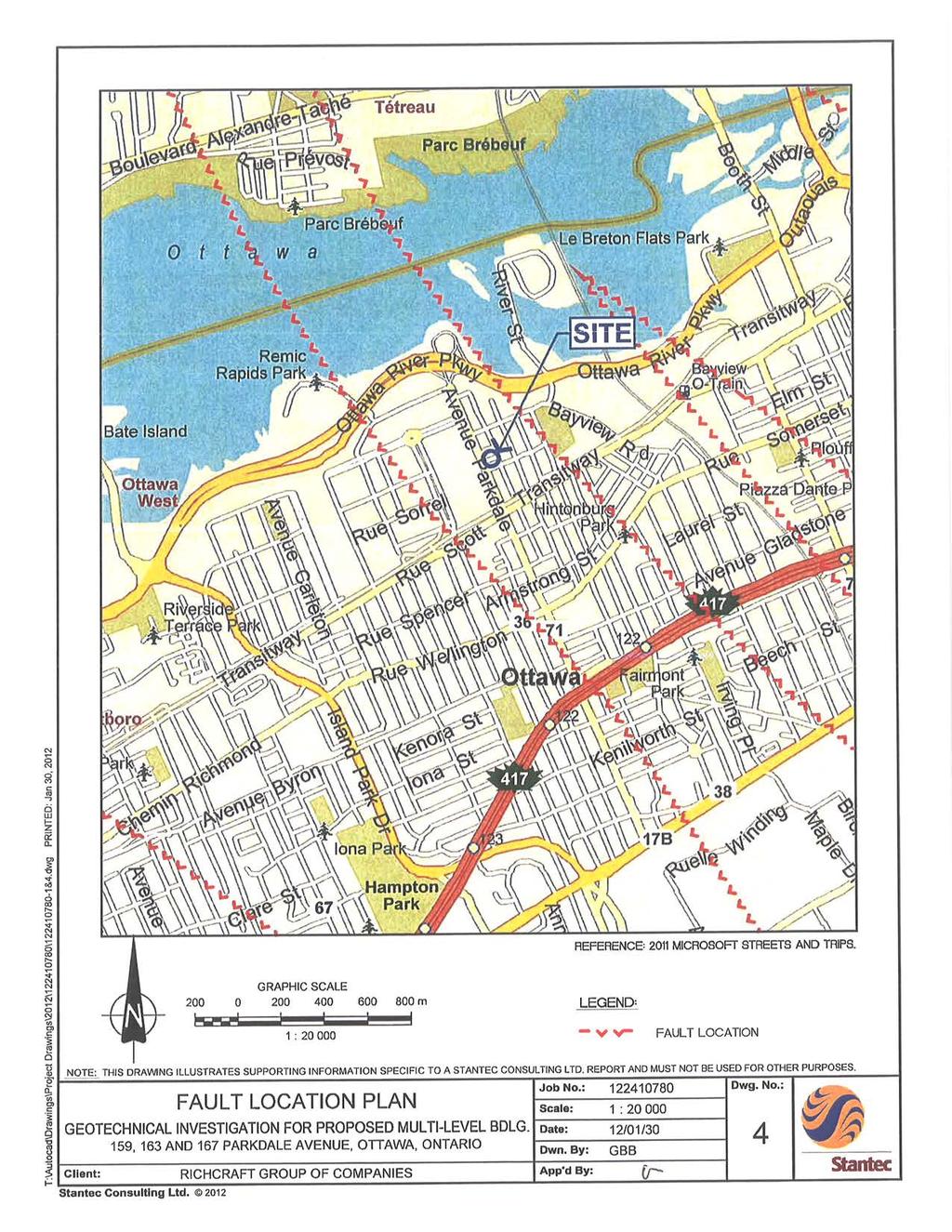
10 FINAL GEOTECHNICAL REPORT May SEISMIC SITE CLASSIFICATION Existing V S30 measurements around the study site were reviewed to determine the site class according to the 2006 Ontario Building Code. The measurements were obtained from the geological Survey of Canada Surficial Boreholes for the National Capital Area. The data is accessible through the Carleton University website called the Interactive Surface Geography Map for the City of Ottawa. The selected boreholes are illustrated in Drawing No. 3 in Appendix B and the corresponding shear wave velocity information is shown in Table 6.2. This Table provides the average shear wave velocity in top 30 m for the studied sites (V s30 ). Based on V s30 values, the recommended site classification for seismic site response for the building is Site Class A in accordance with Table A of the 2006 Ontario Building Code. Table 6.2: Shear Wave Velocity Information of Selected Boreholes Borehole Name Borehole ID Bedrock Bedrock Velocity Range V Depth (m) s30 (m/sec) (m/sec) a UGE b UGE c UGE d UGE e UGE The location of the proposed building and known faults was evaluated. Drawing No. 4 in Appendix B shows the location of the nearest faults. The drawing indicates that the proposed building is not located on a fault. 6.4 GROUNDWATER CONTROL The groundwater level within monitoring well MW12-7 was measured at elevation 54.3 m. The proposed below grade parking levels will be below the groundwater level. The design of the below grade parking levels should consider the groundwater level. The below grade levels could be designed to be waterproof or a subdrain system could be provided. The subdrains should be founded at least 400 mm below the underside of the floor slab and should be connected to a frost free outlet. If subdrains are proposed, the floor slab should be supported on a 400 mm thick layer of clear stone for drainage. 6.5 PIPE BEDDING AND BACKFILL Bedding for utilities should be placed in accordance with the pipe design requirements. It is recommended that a minimum of 150 mm to 200 mm of OPSS Granular A be placed below the pipe invert as bedding material. Granular pipe backfill placed above the invert should consist of Granular A material. A minimum of 300 mm vertical and side cover should be provided. These materials should be compacted to at least 95% of SPMDD. 7
11 FINAL GEOTECHNICAL REPORT May 2012 Backfill for service trenches in landscaped areas may consist of excavated material replaced and compacted in lifts. Where the service trenches extend below paved areas, the trench should be backfilled with OPSS Select Subgrade Material (SSM) from the top of the pipe cover to within 1.2 m of the proposed pavement surface, placed in lifts and compacted to at least 95% of SPMDD. The material used within the upper 1.2 m and below the subgrade line should be similar to that exposed in the trench walls to prevent differential frost heave, placed in lifts and compacted to at least 95% of SPMDD. Different abutting materials within this zone will require a 3 horizontal to 1 vertical frost taper in order to minimize the effects of differential frost heaving. Excavations for catch basins and manholes should be backfilled with compacted granular material. A 3 horizontal to 1 vertical frost taper should be built within the upper 1.2 m. The joints between catch basin or manhole sections must be wrapped with non-woven geotextile. It should be noted that reuse of the site generated material will be highly dependent on the material s moisture content at time of placement. Backfill should be compacted in lifts not exceeding 300 mm. 6.6 TEMPORARY EXCAVATIONS AND BACKFILLING Excavations in Soil The shallow silty sand fill (maximum encountered thickness of 1.3 m) present at the site is considered a Type 3 soil in accordance with the Occupational Health and Safety Act (OHSA) and Regulations for Construction Projects. Temporary excavations in the overburden may be supported or should be sloped at 1 horizontal to 1 vertical from the base of the excavation and as per the requirements of OHSA. Alternatively, sheet piling or other support methods will be required. Excavations should be inspected regularly for signs of instability and flattened as required. The excavation support system should be designed to resist loads from traffic and foundations from adjacent structures Groundwater Groundwater was encountered during this geotechnical investigation within the depths of the anticipated excavations. Though soils and bedrock permeability measurements were not included as part of this investigation, it is expected that dewatering of the excavations will be possible using conventional sump and pump techniques. It should be noted that groundwater elevations fluctuate seasonally. Dewatering of the excavation is not anticipated to cause settlement of soils due to groundwater lowering in the vicinity of the site. 8
12 FINAL GEOTECHNICAL REPORT May Excavations in Bedrock Drilling and blasting and hoe ramming techniques will be required to excavate bedrock. Temporary excavation in bedrock may be carried out at near vertical slopes, provided the trench sides are cleared of loose rock prior to workers entering the trench. If the bedrock is overly fractured such that the loose rock cannot be entirely removed, a temporary rock catchment system such as a wire mesh system should be used. The catchment system should be designed to contain and/or prevent loose rock particles from falling on workers within the excavation. Bedrock excavation sidewalls adjacent to existing building foundations should be supported to ensure the stability of the existing buildings Earth Pressures on Shoring Systems Earth pressures will need to be considered in the design of shoring systems for temporary excavations during construction. Table 6.3 gives the coefficients of lateral earth pressure for shoring systems. These values are based on the assumption that a horizontal back slope will be utilized behind the shoring system. Table 6.3: Lateral Earth Pressure Parameters Parameter Native Fill OPSS Granular A OPSS Granular B Type I Unit Weight (kn/m 3 ) Angle of Internal Friction, Φ Coefficient of Passive Earth Pressure, K p Coefficient of at Rest Earth Pressure, K o Coefficient of Active Earth Pressure, K a Sliding resistance can be calculated using the following unfactored friction coefficients, outlined in Table 6.4. Table 6.4: Unfactored Friction Coefficients Condition Unfactored Friction Coefficient Between Concrete and Structural Fill 0.55 Between Concrete and Clean Bedrock Rock Anchors Rock anchors could be used to ensure stability of temporary shoring system and resist uplift forces. For the design of rock anchors extending into bedrock, the following design parameters may be considered for the rock mass. 9
13 FINAL GEOTECHNICAL REPORT May 2012 A rock to grout working bond stress of 1000 kpa may be used for holes grouted with nonshrink grout having a minimum compressive strength of 30 MPa. The minimum fixed anchor length (i.e. the length over which the rock to grout bond stress is developed) should be no less than 3 m. The unbounded length of anchor should be equal to the height of the rock cone and less half the bonded length. To ensure against the possibility of a rock mass failure, the following design parameters should be used: Submerged Unit weight of rock = 16 kn/m3 A 90 (apex angle) failure cone with the apex located at the midpoint of the bonded length as shown on the sheet titled Rock Anchor: Resistance to Rock Mass Failure in Appendix E. The bond stress used by the contractor for design should be confirmed by full scale testing of anchors Foundation Backfill Backfill within the footprint of the proposed buildings should consist of OPSS Granular A compacted to 100% SPMDD. Exterior foundation backfill should consist of a material meeting the requirements of OPSS Select Subgrade Material (SSM). Exterior foundation backfill shall be placed in lifts no thicker than 300 mm and compacted using suitable compaction equipment to at least 95% of SPMDD. Care should be taken immediately adjacent to the foundation walls to avoid over-compaction of the soil which could result in damage to the walls. 6.7 CEMENT TYPE AND CORROSION POTENTIAL One representative groundwater sample was submitted to Paracel Laboratories Ltd. in Ottawa, Ontario, for ph, chloride, sulphate and resistivity testing. The test results are summarized in Table 6.5. Table 6.5: ph, Sulphate, Chloride and Resistivity Analysis Results Borehole No. ph Sulphate (µg/g) Resistivity (0.01 ohm.m) Chloride (µg/g) MW One concentration of soluble sulphate provides an indication of the degree of sulphate attack that is expected for concrete in contact with soil and groundwater at the site. The soluble sulphate is 104 µg/g. Soluble sulphate concentrations less than 1000 µg/g generally indicate that a low degree of sulphate attack is expected for concrete in contact with soil and groundwater. Type GU Portland Cement should therefore be suitable for use in concrete at this site. 10
14 FINAL GEOTECHNICAL REPORT May 2012 The ph, resistivity and chloride concentration provide an indication of the degree of corrosiveness of the sub-surface environment. The soil ph was 7.7 which is within what is considered the normal range for soil ph of 5.5 to 9.0. The ph levels of the tested soil do not indicate a highly corrosive environment. The test results provided in the Table 6.5 can be used to aid in the selection of coatings and corrosion protection systems for buried steel objects. 6.8 PAVEMENT STRUCTURE RECOMMENDATIONS It has been assumed that the parking areas will be used mostly by passenger vehicles and the access roads will be used by delivery trucks and fire vehicles. The subgrade in paved areas should be prepared as described in Section 6.1 above. The following minimum pavement structures are recommended: Table 6.6: Recommended Pavement Design Heavy Duty Parking Access Material Roads Standard Duty Parking Area SP 12.5 Asphaltic Concrete 40 mm 50 mm SP 19 Asphaltic Concrete 50 mm - Granular Base Course, OPSS Granular A 150 mm 150 mm Granular Subbase Course, OPSS Granular B Type II 400 mm 300 mm It is estimated that the service life prior to major rehabilitation for the above pavement structures is 20 years provided they are properly maintained. The pavement surface and the underlying subgrade should be graded to direct runoff water towards suitable drainage. All granular materials should be tested and approved by a geotechnical engineer prior to delivery to the site. Both base and subbase materials should be compacted to at least 100% SPMDD. Asphalt should be compacted to at least 97% Marshal bulk density. It is recommended that the lateral extent of the subbase and base layers not be terminated in a vertical fashion immediately behind the curb line. A taper with a grade of 5 horizontal to 1 vertical is recommended in the subgrade line to minimize differential frost heave problems under sidewalks. 6.9 VIBRATIONS MONITORING AND PRE-CONSTRUCTION SURVEYS The required construction activities for the proposed building will generate some vibrations that will be perceptible to nearby residents. The vibrations are expected to be greatest during bedrock excavation by blasting/mechanical methods. It is recommended that pre-construction surveys of all structures be carried out in accordance with OPSS 120 General Specifications for the Use of Explosives. It is recommended that construction vibrations generally be limited to a maximum peak particle velocity as outlined in OPSS 120. Should there be structures in the area sensitive to vibrations, 11
15 FINAL GEOTECHNICAL REPORT May 2012 more stringent specifications should be developed by a vibration specialist. For instance, the particle velocity should be limited to 10 mm/sec if there is any historic building in the area. Vibration monitoring should be carried out prior to and throughout the construction period. No blasting should be carried out within a distance of 200 m from any water storage reservoir, pumping station, water works transformer station or water storage tank without prior approval by the owner of the facility. 12
16
17 FINAL GEOTECHNICAL REPORT May 2012 APPENDIX A Statement of General Conditions

18 STATEMENT OF GENERAL CONDITIONS USE OF THIS REPORT: This report has been prepared for the sole benefit of the Client or its agent and may not be used by any third party without the express written consent of Stantec Consulting Ltd. and the Client. Any use which a third party makes of this report is the responsibility of such third party. BASIS OF THE REPORT: The information, opinions, and/or recommendations made in this report are in accordance with Stantec Consulting Ltd. s present understanding of the site specific project as described by the Client. The applicability of these is restricted to the site conditions encountered at the time of the investigation or study. If the proposed site specific project differs or is modified from what is described in this report or if the site conditions are altered, this report is no longer valid unless Stantec Consulting Ltd. is requested by the Client to review and revise the report to reflect the differing or modified project specifics and/or the altered site conditions. STANDARD OF CARE: Preparation of this report, and all associated work, was carried out in accordance with the normally accepted standard of care in the state or province of execution for the specific professional service provided to the Client. No other warranty is made. INTERPRETATION OF SITE CONDITIONS: Soil, rock, or other material descriptions, and statements regarding their condition, made in this report are based on site conditions encountered by Stantec Consulting Ltd. at the time of the work and at the specific testing and/or sampling locations. Classifications and statements of condition have been made in accordance with normally accepted practices which are judgmental in nature; no specific description should be considered exact, but rather reflective of the anticipated material behavior. Extrapolation of in situ conditions can only be made to some limited extent beyond the sampling or test points. The extent depends on variability of the soil, rock and groundwater conditions as influenced by geological processes, construction activity, and site use. VARYING OR UNEXPECTED CONDITIONS: Should any site or subsurface conditions be encountered that are different from those described in this report or encountered at the test locations, Stantec Consulting Ltd. must be notified immediately to assess if the varying or unexpected conditions are substantial and if reassessments of the report conclusions or recommendations are required. Stantec Consulting Ltd. will not be responsible to any party for damages incurred as a result of failing to notify Stantec Consulting Ltd. that differing site or subsurface conditions are present upon becoming aware of such conditions. PLANNING, DESIGN, OR CONSTRUCTION: Development or design plans and specifications should be reviewed by Stantec Consulting Ltd., sufficiently ahead of initiating the next project stage (property acquisition, tender, construction, etc), to confirm that this report completely addresses the elaborated project specifics and that the contents of this report have been properly interpreted. Specialty quality assurance services (field observations and testing) during construction are a necessary part of the evaluation of sub-subsurface conditions and site preparation works. Site work relating to the recommendations included in this report should only be carried out in the presence of a qualified geotechnical engineer; Stantec Consulting Ltd. cannot be responsible for site work carried out without being present.
19 FINAL GEOTECHNICAL REPORT May 2012 APPENDIX B Key Plan Borehole Location Plan V S30 Measurement Location Plan Fault Location Plan

20

21
22
23
24 FINAL GEOTECHNICAL REPORT May 2012 APPENDIX C Symbols and Terms Used on Borehole and Test Pit Records Borehole and Test Pit Records Field Core Logs Bedrock Core Photos
25 SOIL DESCRIPTION SYMBOLS AND TERMS USED ON BOREHOLE AND TEST PIT RECORDS Terminology describing common soil genesis: Topsoil - mixture of soil and humus capable of supporting vegetative growth Peat - mixture of visible and invisible fragments of decayed organic matter Till - unstratified glacial deposit which may range from clay to boulders Fill - material below the surface identified as placed by humans (excluding buried services) Terminology describing soil structure: Desiccated - having visible signs of weathering by oxidization of clay minerals, shrinkage cracks, etc. Fissured - having cracks, and hence a blocky structure Varved - composed of regular alternating layers of silt and clay Stratified - composed of alternating successions of different soil types, e.g. silt and sand Layer - > 75 mm in thickness Seam - 2 mm to 75 mm in thickness Parting - < 2 mm in thickness Terminology describing soil types: The classification of soil types are made on the basis of grain size and plasticity in accordance with the Unified Soil Classification System (USCS) (ASTM D 2487 or D 2488). The classification excludes particles larger than 76 mm (3 inches). The USCS provides a group symbol (e.g. SM) and group name (e.g. silty sand) for identification. Terminology describing cobbles, boulders, and non-matrix materials (organic matter or debris): Terminology describing materials outside the USCS, (e.g. particles larger than 76 mm, visible organic matter, construction debris) is based upon the proportion of these materials present: Trace, or occasional Less than 10% Some 10-20% Frequent > 20% Terminology describing compactness of cohesionless soils: The standard terminology to describe cohesionless soils includes compactness (formerly "relative density"), as determined by the Standard Penetration Test N-Value (also known as N-Index). A relationship between compactness condition and N-Value is shown in the following table. Compactness Condition SPT N-Value Very Loose <4 Loose 4-10 Compact Dense Very Dense >50 Terminology describing consistency of cohesive soils: The standard terminology to describe cohesive soils includes the consistency, which is based on undrained shear strength as measured by in situ vane tests, penetrometer tests, or unconfined compression tests. Consistency Undrained Shear Strength kips/sq.ft. kpa Very Soft <0.25 <12.5 Soft Firm Stiff Very Stiff Hard >4.0 >200 SYMBOLS AND TERMS USED ON BOREHOLE AND TEST PIT RECORDS MARCH 2009 Page 1 of 3
26 ROCK DESCRIPTION Terminology describing rock quality: RQD Rock Mass Quality 0-25 Very Poor Poor Fair Good Excellent Rock quality classification is based on a modified core recovery percentage (RQD) in which all pieces of sound core over 100 mm long are counted as recovery. The smaller pieces are considered to be due to close shearing, jointing, faulting, or weathering in the rock mass and are not counted. RQD was originally intended to be done on NW core; however, it can be used on different core sizes if the bulk of the fractures caused by drilling stresses are easily distinguishable from in situ fractures. The terminology describing rock mass quality based on RQD is subjective and is underlain by the presumption that sound strong rock is of higher engineering value than fractured weak rock. Terminology describing rock mass: Spacing (mm) Joint Classification Bedding, Laminations, Bands > 6000 Extremely Wide Very Wide Very Thick Wide Thick Moderate Medium Close Thin Very Close Very Thin <20 Extremely Close Laminated <6 - Thinly Laminated Terminology describing rock strength: Strength Classification Unconfined Compressive Strength (MPa) Extremely Weak < 1 Very Weak 1 5 Weak 5 25 Medium Strong Strong Very Strong Extremely Strong > 250 Terminology describing rock weathering: Term Fresh Slightly Weathered Moderately Weathered Highly Weathered Completely Weathered Description No visible signs of rock weathering. Slight discolouration along major discontinuities Discolouration indicates weathering of rock on discontinuity surfaces. All the rock material may be discoloured. Less than half the rock is decomposed and/or disintegrated into soil. More than half the rock is decomposed and/or disintegrated into soil. All the rock material is decomposed and/or disintegrated into soil. The original mass structure is still largely intact. SYMBOLS AND TERMS USED ON BOREHOLE AND TEST PIT RECORDS MARCH 2009 Page 2 of 3
27 STRATA PLOT Strata plots symbolize the soil or bedrock description. They are combinations of the following basic symbols. The dimensions within the strata symbols are not indicative of the particle size, layer thickness, etc. Boulders Cobbles Gravel Sand Silt Clay Organics Asphalt Concrete Fill Igneous Bedrock Metamorphic Bedrock Sedimentary Bedrock SAMPLE TYPE SS ST DP PS BS WS HQ, NQ, BQ, etc. Split spoon sample (obtained by performing the Standard Penetration Test) Shelby tube or thin wall tube Direct-Push sample (small diameter tube sampler hydraulically advanced) Piston sample Bulk sample Wash sample Rock core samples obtained with the use of standard size diamond coring bits. WATER LEVEL MEASUREMENT measured in standpipe, piezometer, or well inferred RECOVERY For soil samples, the recovery is recorded as the length of the soil sample recovered. For rock core, recovery is defined as the total cumulative length of all core recovered in the core barrel divided by the length drilled and is recorded as a percentage on a per run basis. N-VALUE Numbers in this column are the field results of the Standard Penetration Test: the number of blows of a 140 pound (64 kg) hammer falling 30 inches (760 mm), required to drive a 2 inch (50.8 mm) O.D. split spoon sampler one foot (305 mm) into the soil. For split spoon samples where insufficient penetration was achieved and N-values cannot be presented, the number of blows are reported over sampler penetration in millimetres (e.g. 50/75). Some design methods make use of N value corrected for various factors such as overburden pressure, energy ratio, borehole diameter, etc. No corrections have been applied to the N-values presented on the log. DYNAMIC CONE PENETRATION TEST (DCPT) Dynamic cone penetration tests are performed using a standard 60 degree apex cone connected to A size drill rods with the same standard fall height and weight as the Standard Penetration Test. The DCPT value is the number of blows of the hammer required to drive the cone one foot (305 mm) into the soil. The DCPT is used as a probe to assess soil variability. OTHER TESTS S H k γ G s CD CU UU DS C Q u I p Sieve analysis Hydrometer analysis Laboratory permeability Unit weight Specific gravity of soil particles Consolidated drained triaxial Consolidated undrained triaxial with pore pressure measurements Unconsolidated undrained triaxial Direct Shear Consolidation Unconfined compression Point Load Index (I p on Borehole Record equals I p(50) in which the index is corrected to a reference diameter of 50 mm) Single packer permeability test; test interval from depth shown to bottom of borehole Double packer permeability test; test interval as indicated Falling head permeability test using casing Falling head permeability test using well point or piezometer SYMBOLS AND TERMS USED ON BOREHOLE AND TEST PIT RECORDS MARCH 2009 Page 3 of 3
28
29
30
31
32
33
34
35
36
37
38
39
40
41
42
43
44
45
46
47


48 Project No.: Project Name: Parkdale Development Rockcore Photographs Rock Core Photo No.: 1 Borehole: MW 12-7 Depth: m Rock Core Photo No.: 2 Borehole: MW 12-7 Depth: m


49 Project No.: Project Name: Parkdale Development Rockcore Photographs Rock Core Photo No.: 3 Borehole: MW 12-7 Depth: m Rock Core Photo No.: 4 Borehole: MW 12-7 Depth: m


50 Project No.: Project Name: Parkdale Development Rockcore Photographs Rock Core Photo No.: 5 Borehole: MW 12-7 Depth: m Rock Core Photo No.: 6 Borehole: MW 12-7 Depth: m


51 Project No.: Project Name: Parkdale Development Rockcore Photographs Rock Core Photo No.: 7 Borehole: MW 12-7 Depth: m Rock Core Photo No.: 8 Borehole: MW 12-8 Depth: m


52 Project No.: Project Name: Parkdale Development Rockcore Photographs Rock Core Photo No.: 9 Borehole: BH 12-8 Depth: m Rock Core Photo No.: 10 Borehole: MW 12-8 Depth: m


53 Project No.: Project Name: Parkdale Development Rockcore Photographs Rock Core Photo No.: 11 Borehole: BH 12-8 Depth: m Rock Core Photo No.: 12 Borehole: BH 12-8 Depth: m


54 Project No.: Project Name: Parkdale Development Rockcore Photographs Rock Core Photo No.: 13 Borehole: BH 12-8 Depth: m Rock Core Photo No.: 14 Borehole: BH 12-8 Depth: m


55 Project No.: Project Name: Parkdale Development Rockcore Photographs Rock Core Photo No.: 15 Borehole: BH 12-8 Depth: m Rock Core Photo No.: 16 Borehole: BH 12-8 Depth: m

56 Project No.: Project Name: Parkdale Development Rockcore Photographs Rock Core Photo No.: 17 Borehole: BH 12-8 Depth: m v:\01224\active\ xx\ \rock photos\photo_pages_rockcores.docx
57 FINAL GEOTECHNICAL REPORT May 2012 APPENDIX D Laboratory Test Results


58 Unified Soil Classification System SAND Gravel CLAY & SILT Fine Medium Coarse Fine Coarse 100 U.S. Std. Sieve No Percent Passing Sample ID Percent Retained BH12-8 SS MW12-10 SS Grain Size in Millimetres GRAIN SIZE DISTRIBUTION FILL Figure No. 1 Project No
59
60
61
62 FINAL GEOTECHNICAL REPORT May 2012 APPENDIX E Rock Anchor: Resistance to Rock Mass Failure
63
Final Geotechnical Report Proposed Tower B Multi-Level Building at the Corner of Parkdale Avenue and Bullman Street Ottawa, ON
 Final Geotechnical Report Proposed Tower B Multi-Level Building at the Corner of Parkdale Avenue and Bullman Street Ottawa, ON Prepared for: Richcraft Group of Companies 2280 St. Laurent Blvd, Ottawa,
Boreholes. Implementation. Boring. Boreholes may be excavated by one of these methods: 1. Auger Boring 2. Wash Boring 3.
 Implementation Boreholes 1. Auger Boring 2. Wash Boring 3. Rotary Drilling Boring Boreholes may be excavated by one of these methods: 4. Percussion Drilling The right choice of method depends on: Ground
February 22, 2016 AG File No
 Ainley Graham & Associates Limited 1-50 Grant Timmins Drive, Kingston, Ontario, K7M 8N2 Tel: (343) 266-0002 Fax: (343) 266-0028 E-mail Kingston@ainleygroup.com February 22, 2016 AG File No. 15062-1 Ministry
B-1 BORE LOCATION PLAN. EXHIBIT Drawn By: 115G BROOKS VETERINARY CLINIC CITY BASE LANDING AND GOLIAD ROAD SAN ANTONIO, TEXAS.
 N B-1 SYMBOLS: Exploratory Boring Location Project Mngr: BORE LOCATION PLAN Project No. GK EXHIBIT Drawn By: 115G1063.02 GK Scale: Checked By: 1045 Central Parkway North, Suite 103 San Antonio, Texas 78232
patersongroup Design for Earthquakes Consulting Engineers May 19, 2016 File: PG3733-LET.01
 patersongroup May 19, 2016 File: PG3733-LET.01 Hydro Ottawa Limited c/o Cresa Toronto 170 University Avenue, Suite 1 Toronto, Ontario M5H 3B3 Attention: Ms. Barbara Wright Consulting Engineers 154 Colonnade
SITE INVESTIGATION 1
 SITE INVESTIGATION 1 Definition The process of determining the layers of natural soil deposits that will underlie a proposed structure and their physical properties is generally referred to as site investigation.
GEOTECHNICAL REPORT CBSA Facility Redevelopment Thousand Islands International Crossing Lansdowne, Ontario
 GEOTECHNICAL REPORT CBSA Facility Redevelopment Thousand Islands International Crossing Lansdowne, Ontario Prepared For: The Federal Bridge Corporation Limited SPL Project No.: 10001084 Report Date: January
patersongroup 1.0 Geotechnical Desktop Review Consulting Engineers April 18, 2017 PG4080-LET.01
 patersongroup April 18, 2017 PG080-LET.01 2015-2017 RR Ltd 311 Richmond Road, Suite 203 Ottawa, ON K1Z 6X3 Attention: Subject: Mr. Jonah Bonn Geotechnical Desktop Review Proposed Drive-Thru Lanes 2015-2017
Chapter 12 Subsurface Exploration
 Page 12 1 Chapter 12 Subsurface Exploration 1. The process of identifying the layers of deposits that underlie a proposed structure and their physical characteristics is generally referred to as (a) subsurface
FINAL REPORT, GEOTECHNICAL INVESTIGATION, NORTHWEST RIVER BRIDGE RECONSTRUCTION, TERRA NOVA NATIONAL PARK, NL. File No:
 FINAL REPORT, GEOTECHNICAL INVESTIGATION, NORTHWEST RIVER BRIDGE RECONSTRUCTION, TERRA NOVA NATIONAL PARK, NL File No: 6847 Prepared for: Harbourside Engineering Consultants 9 Waverly Road, Suite Dartmouth
patersongroup memorandum 1.0 Field Investigation consulting engineers
 consulting engineers memorandum to: KDSA Development Corporation - Ms. Susan Anglin - susananglin6@gmail.com re: Pavement Structure Recommendations - Shady Maple Road Proposed Braeburn Estates Residential
ENCE 3610 Soil Mechanics. Site Exploration and Characterisation Field Exploration Methods
 ENCE 3610 Soil Mechanics Site Exploration and Characterisation Field Exploration Methods Geotechnical Involvement in Project Phases Planning Design Alternatives Preparation of Detailed Plans Final Design
ATTACHMENT A PRELIMINARY GEOTECHNICAL SUMMARY
 ATTACHMENT A PRELIMINARY GEOTECHNICAL SUMMARY Kevin M. Martin, P.E. KMM Geotechnical Consultants, LLC 7 Marshall Road Hampstead, NH 0384 603-489-6 (p)/ 603-489-8 (f)/78-78-4084(m) kevinmartinpe@aol.com
Gotechnical Investigations and Sampling
 Gotechnical Investigations and Sampling Amit Prashant Indian Institute of Technology Gandhinagar Short Course on Geotechnical Investigations for Structural Engineering 12 14 October, 2017 1 Purpose of
Subsurface Investigation Proposed Commercial Building 528 March Road Ottawa, Ontario
 Subsurface Investigation Proposed Commercial Building 8 March Road Ottawa, Ontario Houle Chevrier Engineering Ltd. 80 Wescar Lane Ottawa, Ontario K0A L0 www.hceng.ca Submitted to: Broccolini Construction
patersongroup Geotechnical Investigation Proposed Elementary School 2300 Esprit Drive Ottawa, Ontario Prepared For Ottawa Catholic School Board
 Geotechnical Engineering Environmental Engineering Hydrogeology Geological Engineering Materials Testing Building Science Proposed Elementary School 300 Esprit Drive Archaeological Services Prepared For
patersongroup Geotechnical Investigation Proposed Industrial Building 1670 Comstock Road Ottawa, Ontario Prepared For Simluc Contractors Limited
 Geotechnical Engineering Environmental Environmental Engineering Engineering Hydrogeology Hydrogeology Geological Engineering Geological Engineering Materials Testing Materials Testing Building Science
Updated Subsurface Investigation Block A Heritage Hills Development 124 Battersea Crescent Ottawa, Ontario
 Updated Subsurface Investigation Block A Heritage Hills Development 124 Battersea Crescent Ottawa, Ontario Submitted to: Brigil Homes 98 rue Lois Gatineau, Quebec J8Y 3R7 Updated Subsurface Investigation
Geotechnical Investigation Proposed Retirement Residence Goulbourn Forced Road Ottawa, Ontario
 REPORT February 205 REPORT ON Geotechnical Investigation Proposed Retirement Residence Goulbourn Forced Road Ottawa, Ontario Submitted to: Dan Roach, AIA Hawthorne Development LLC c/o Lenity Architecture
General. DATE December 10, 2013 PROJECT No TO Mary Jarvis Urbandale/Riverside South Development Corporation
 DATE December 10, 201 PROJECT No. 10-1121-0260- TO Mary Jarvis Urbandale/Riverside South Development Corporation CC Justin Robitaille, Urbandale Jonathan Párraga, J.L. Richards & Associates Limited FROM
GEOTECHNICAL INVESTIGATION REPORT
 GEOTECHNICAL INVESTIGATION REPORT DH 1404-05 ACCOMODATE SPECIALIZED EQUIPMENT, DWYER HILL TRAINING CENTRE RICHMOND, ONTARIO Prepared for: Defence Construction Canada (DCC) Date: February 2016 Report No.:
The process of determining the layers of natural soil deposits that will underlie a proposed structure and their physical properties is generally
 The process of determining the layers of natural soil deposits that will underlie a proposed structure and their physical properties is generally referred to as sub surface investigation 2 1 For proper
 SOIL CLASSIFICATION CHART COARSE-GRAINED SOILS MORE THAN 50% RETAINED ON NO.200 SIEVE FINE-GRAINED SOILS 50% OR MORE PASSES THE NO.200 SIEVE PRIMARY DIVISIONS GRAVELS MORE THAN 50% OF COARSE FRACTION RETAINED
Reference No S072 APRIL 2012
 A REPORT TO SOLMAR DEVELOPMENT CORP. A PRELIMINARY SOIL INVESTIGATION FOR PROPOSED SUBDIVISION DEVELOPMENT NORTHEAST OF SIDEROAD 5 AND 0 LINE TOWN OF ERIN Reference No. 202-S072 APRIL 202 DISTRIBUTION
Geotechnical Investigation Proposed Retirement Residence Timberwalk Ottawa, Ontario
 September 6 REPORT ON Geotechnical Investigation Proposed Retirement Residence Timberwalk Ottawa, Ontario Submitted to: Claridge Homes Corporation - Gladstone Avenue Ottawa, ON KP Y6 REPORT Report Number:
Civil Engineering, Surveying and Environmental Consulting WASP0059.ltr.JLS.Mich Ave Bridge Geotech.docx
 2365 Haggerty Road South * Canton, Michigan 48188 P: 734-397-3100 * F: 734-397-3131 * www.manniksmithgroup.com August 29, 2012 Mr. Richard Kent Washtenaw County Parks and Recreation Commission 2330 Platt
GEOTECHNICAL INVESTIGATION REPORT
 GEOTECHNICAL INVESTIGATION REPORT SOIL INVESTIGATION REPORT FOR STATIC TEST FACILITY FOR PROPELLANTS AT BDL, IBRAHIMPATNAM. Graphics Designers, M/s Architecture & Engineering 859, Banjara Avenue, Consultancy
APPENDIX E SOILS TEST REPORTS
 Otsego County, NY Site Work Specifications APPENDIX E SOILS TEST REPORTS Blue Wing Services, Inc. July 1, 2010 Blue Wing Services May 20, 2010 Page 2 the site, was not made available to Empire at this
Depth (ft) USCS Soil Description TOPSOIL & FOREST DUFF
 USCS Soil Description TOPSOIL & FOREST DUFF") Test Pit No. TP-6 Location: Latitude 47.543003, Longitude -121.980441 Approximate Ground Surface Elevation: 1,132 feet Depth (ft) USCS Soil Description 0 1.5 1.5 5.0 SM 5.0 8.0 SM Loose to medium dense,
Test Pit No. TP-6 Location: Latitude 47.543003, Longitude -121.980441 Approximate Ground Surface Elevation: 1,132 feet Depth (ft) USCS Soil Description 0 1.5 1.5 5.0 SM 5.0 8.0 SM Loose to medium dense,
APPENDIX A GEOTECHNICAL REPORT
 The City of Winnipeg Bid Opportunity No. 529-2017 Template Version: C420170317 - RW APPENDIX A GEOTECHNICAL REPORT Quality Engineering Valued Relationships KGS Group 2017 Industrial Street Rehabilitation
patersongroup 1.0 Field Observations Consulting Engineers January 20, 2014 File: PG3145-LET.01 City View Curling Club 50 Capilano Drive
 January 0, 04 File: P345-LET.0 City View Curling Club 50 Capilano Drive Ottawa, Ontario KE 64 Attention: Ms. Cheryl Carroll Consulting Engineers 54 Colonnade Road South Ottawa, Ontario KE 7J5 Tel: (63)
 Project: ITHACA-TOMPKINS REGIONAL AIRPORT EXPANSION Project Location: ITHACA, NY Project Number: 218-34 Key to Soil Symbols and Terms TERMS DESCRIBING CONSISTENCY OR CONDITION COARSE-GRAINED SOILS (major
KDOT Geotechnical Manual Edition. Table of Contents
 KDOT Geotechnical Manual 2007 Edition The KDOT Geotechnical Manual is available two volumes. Both volumes are very large electronic (pdf) files which may take several minutes to download. The table of
Manual on Subsurface Investigations National Highway Institute Publication No. FHWA NHI Federal Highway Administration Washington, DC
 Manual on Subsurface Investigations National Highway Institute Publication No. FHWA NHI-01-031 Federal Highway Administration Washington, DC Geotechnical Site Characterization July 2001 by Paul W. Mayne,
Geotechnical Investigation Juneau Seawalk - Taku Fisheries to Miner s Wharf Juneau, Alaska DM&A Job No
 Duane Miller & Associates 5821 Arctic Boulevard, Suite A Anchorage, AK 99518-1654 (907) 644-3200 Fax 644-0507 Arctic & Geotechnical Engineering May 4, 2006 Tetra Tech/KCM, Inc. 1971 First Avenue Seattle,
Geotechnical Investigation Report
 Geotechnical Investigation Report Proposed Salt Storage Shed Majestic Hills Drive Hamilton Township, Ontario Hamilton Township 7 Pido Road Peterborough Ontario K9J 6X7 Canada 568 0 Report No June 08 Table
ROCK EXCAVATION (GRADING) OPSS 206 INDEX
 OPSS 206 INDEX") 206-2 - OPSS 206 INDEX 206-2.1 GENERAL 206-2.1.1 Classification of Rock Materials 206-2.1.2 Tender Items 206-2.1.3 Other Excavation Tender Items 206-2.1.4 Specifications 206-2.1.5 Special Provisions 206-2.1.6
206-2 - OPSS 206 INDEX 206-2.1 GENERAL 206-2.1.1 Classification of Rock Materials 206-2.1.2 Tender Items 206-2.1.3 Other Excavation Tender Items 206-2.1.4 Specifications 206-2.1.5 Special Provisions 206-2.1.6
Field Exploration. March 31, J-U-B ENGINEERS, Inc. 115 Northstar Avenue Twin Falls, Idaho Attn: Mr. Tracy Ahrens, P. E. E:
 March 31, 201 11 Northstar Avenue 83301 Attn: Mr. Tracy Ahrens, P. E. E: taa@jub.com Re: Geotechnical Data Report Preliminary Phase 1 Field Exploration Revision No. 1 Proposed Rapid Infiltration Basin
Prepared for. Mr. Denis A. Verdon 445, Wilson Road Rockland, Ontario K4K 1K7
 GEOTECHNICAL INVESTIGATION Proposed Verdon Subdivision Part of Lot 16, Concession I (Old Survey) Geographic Township of Clarence Now City of Clarence-Rockland Prepared for Mr. Denis A. Verdon 445, Wilson
Geotechnical Engineering Study, Conifer Senior High School Football Field Improvements, Conifer, Colorado
 2390 South Lipan Street Denver, CO 80223 phone: (303) 742-9700 fax: (303) 742-9666 email: kadenver@kumarusa.com www.kumarusa.com Office Locations: Denver (HQ), Colorado Springs, Fort Collins, and Frisco,
GEOTECHNICAL INVESTIGATION Paq tnkek First Nation Underpass (Ant 275) Antigonish County, Nova Scotia
 Antigonish County, Nova Scotia") GEOTECHNICAL INVESTIGATION Paq tnkek First Nation Underpass (Ant 75) Antigonish County, Nova Scotia Stantec Consulting Ltd. 847 Highway 04 Antigonish NS BG K7 Tel: (90) 86-5805 Fax: (90) 86-5806 Report
GEOTECHNICAL INVESTIGATION Paq tnkek First Nation Underpass (Ant 75) Antigonish County, Nova Scotia Stantec Consulting Ltd. 847 Highway 04 Antigonish NS BG K7 Tel: (90) 86-5805 Fax: (90) 86-5806 Report
DATA REPORT GEOTECHNICAL INVESTIGATION GALVESTON CRUISE TERMINAL 2 GALVESTON, TEXAS
 DATA REPORT GEOTECHNICAL INVESTIGATION GALVESTON CRUISE TERMINAL 2 GALVESTON, TEXAS SUBMITTED TO PORT OF GALVESTON 123 ROSENBERG AVENUE, 8TH FLOOR GALVESTON, TEXAS 77553 BY HVJ ASSOCIATES, INC. HOUSTON,
APPENDIX C. Borehole Data
 APPENDIX C Borehole Data MAJOR DIVISIONS SOIL CLASSIFICATION CHART SYMBOLS GRAPH LETTER TYPICAL DESCRIPTIONS ADDITIONAL MATERIAL
Ottawa, June 5, Ms. Monica Dashwood Director of Development Viva Retirement Communities 3845 Bathurst Street, Suite 206 Toronto, Ontario M3H 3N2
 REPORT: T020846-A2 VIVA RETIREMENT COMMUNITIES Geotechnical Investigation Report Five-Story Retirement Home Strandherd Drive and Tartan Drive Ottawa, Ontario June 5, 2013 Ottawa, June 5, 2013 Ms. Monica
Geotechnical Engineering Subsurface Investigation Report 13-SI-7-BH-1Page)
") Geotechnical Engineering Subsurface Investigation Report 3-SI-7-BH-Page) Canadian Shield Avenue, Kanata, ON, K2K H4 Abstract: This report present the findings of the geotechnical investigation completed
Geotechnical Engineering Subsurface Investigation Report 3-SI-7-BH-Page) Canadian Shield Avenue, Kanata, ON, K2K H4 Abstract: This report present the findings of the geotechnical investigation completed
Appendix H. Geotechnical Investigation Report. Krosno Creek Flood Reduction Project PROJECT FILE REPORT CITY OF PICKERING
 Krosno Creek Flood Reduction Project PROJECT FILE REPORT CITY OF PICKERING Appendix H Geotechnical Investigation Report TMIG THE MUNICIPAL INFRASTRUCTURE GROUP LTD Report on Geotechnical Investigation
Soil Mechanics Brief Review. Presented by: Gary L. Seider, P.E.
 Soil Mechanics Brief Review Presented by: Gary L. Seider, P.E. 1 BASIC ROCK TYPES Igneous Rock (e.g. granite, basalt) Rock formed in place by cooling from magma Generally very stiff/strong and often abrasive
Introduction to Soil Mechanics Geotechnical Engineering-II
 Introduction to Soil Mechanics Geotechnical Engineering-II ground SIVA Dr. Attaullah Shah 1 Soil Formation Soil derives from Latin word Solum having same meanings as our modern world. From Geologist point
A. V T = 1 B. Ms = 1 C. Vs = 1 D. Vv = 1
 Geology and Soil Mechanics 55401 /1A (2002-2003) Mark the best answer on the multiple choice answer sheet. 1. Soil mechanics is the application of hydraulics, geology and mechanics to problems relating
Geology and Soil Mechanics /1A ( ) Mark the best answer on the multiple choice answer sheet.
 Mark the best answer on the multiple choice answer sheet.") Geology and Soil Mechanics 55401 /1A (2003-2004) Mark the best answer on the multiple choice answer sheet. 1. Soil mechanics is the application of hydraulics, geology and mechanics to problems relating
Geology and Soil Mechanics 55401 /1A (2003-2004) Mark the best answer on the multiple choice answer sheet. 1. Soil mechanics is the application of hydraulics, geology and mechanics to problems relating
Limited Geotechnical Engineering Evaluation Classroom Additions Albany County Campus Laramie, Wyoming
 Limited Geotechnical Engineering Evaluation Classroom Additions Albany County Campus 2300 Missile Drive, Cheyenne, Wyoming 82001 Phone 307-635-0222 www.stratageotech.com Limited Geotechnical Engineering
Geotechnical Investigation Proposed Richmond Home Hardware Addition 6379 Perth Street Richmond, Ontario
 Geotechnical Investigation Proposed Richmond Home Hardware Addition 6379 Perth Street Richmond, Ontario Houle Chevrier Engineering Ltd. 180 Wescar Lane Ottawa, Ontario K0A 1L0 www.hceng.ca Submitted to:
Geotechnical Investigation Proposed Commercial Development 1095 Algoma Road Ottawa, Ontario
 February 2016 REPORT ON Geotechnical Investigation Proposed Commercial Development 1095 Algoma Road Ottawa, Ontario Submitted to: 1095 Algoma Road Inc. 1294 Algoma Road Ottawa, Ontario K1B 3W8 REPORT Report
PRELIMINARY GEOTECHNICAL ENGINEERING REPORT. Proposed Re-Development 44 Old Worcester Road Charlton, Massachusetts. Prepared For:
 PRELIMINARY GEOTECHNICAL ENGINEERING REPORT Proposed Re-Development 44 Old Worcester Road Charlton, Massachusetts Prepared For: Meridian Associates, Inc. 500 Cummings Center, Suite 5950 Beverly, Massachusetts
DRAFT GEOTECHNICAL INVESTIGATION REPORT
 DRAFT GEOTECHNICAL INVESTIGATION REPORT PROPOSED NEW SEWER INSTALLATION CITY OF CLARENCE-ROCKLAND, ONTARIO Prepared for: City of Clarence-Rockland 151-03483-00 Date: July 2015 WSP Canada Inc. 500 Greber
Eastgate Parking Lot Geotechnical Investigation
 Eastgate Parking Lot Geotechnical Investigation Cambium Reference No.: 336- March 4, 24 Prepared for: City of Peterborough Cambium Inc. P.O. Box 325 52 Hunter Street East, Peterborough Ontario, K9H G5
GEOTECHNICAL INVESTIGATION REPORT INFRASTRUCTURE PVT LTD
 GEOTECHNICAL INVESTIGATION REPORT Client : TAEIN CONSTRUCTION & INFRASTRUCTURE PVT LTD Office address : Flat No.104, A -Wing,1st floor,gloria Park, Paranjape Scheme, Bavdhan Khurd, Chandni Chowk, Pune
 Photo 1 - Southerly view across 2700 parking lot toward existing building. Multi-residential building borders western side of property in upper right of view. Photo 2 - Southerly view across 2750 parking
10. GEOTECHNICAL EXPLORATION PROGRAM
 Geotechnical site investigations should be conducted in multiple phases to obtain data for use during the planning and design of the tunnel system. Geotechnical investigations typically are performed in
Geotechnical Data Report
 Geotechnical Data Report Downtown Greenville Future Conveyance Study December 1, 2015 Terracon Project No. 86155032 Prepared for: Prepared by: Terracon Consultants, Inc. December 1, 2015 561 Mauldin Road
Pierce County Department of Planning and Land Services Development Engineering Section
 Page 1 of 7 Pierce County Department of Planning and Land Services Development Engineering Section PROJECT NAME: DATE: APPLICATION NO.: PCDE NO.: LANDSLIDE HAZARD AREA (LHA) GEOLOGICAL ASSESSMENT REPORT
June 9, R. D. Cook, P.Eng. Soils Engineer Special Services Western Region PUBLIC WORKS CANADA WESTERN REGION REPORT ON
 PUBLIC WORKS CANADA WESTERN REGION REPORT ON GEOTECHNICAL INVESTIGATION PROPOSED MARTIN RIVER BRIDGE MILE 306.7 MACKENZIE HIGHWAY Submitted by : R. D. Cook, P.Eng. Soils Engineer Special Services Western
APPENDIX A. Borehole Logs Explanation of Terms and Symbols
 APPENDIX A Borehole Logs Explanation of Terms and Symbols Page 153 of 168 EXPLANATION OF TERMS AND SYMBOLS The terms and symbols used on the borehole logs to summarize the results of field investigation
Soils. Technical English - I 10 th week
 Technical English - I 10 th week Soils Soil Mechanics is defined as the branch of engineering science which enables an engineer to know theoretically or experimentally the behavior of soil under the action
Geotechnical Engineering Report
 Geotechnical Engineering Report Turner Turnpike Widening Bridge B Bridge Crossing: South 257 th West Avenue Creek County, Oklahoma June 1, 2016 Terracon Project No. 04155197 Prepared for: Garver, LLC Tulsa,
Slope Stability Assessment Proposed Development 4401 Fallowfield Road Lands Ottawa, Ontario Rev-02
 REPORT August 2014 REPORT ON Slope Stability Assessment Proposed Development 4401 Fallowfield Road Lands Ottawa, Ontario Submitted to: DCR Phoenix Homes 18 Bentley Avenue Ottawa, Ontario K2E 6T8 Report
SOIL INVESTIGATION REPORT. PROPOSED HOUSING DEVELOPMENT PROJECT Coral Spring, Trelawny, Jamaica.
 SOIL INVESTIGATION REPORT PROPOSED HOUSING DEVELOPMENT PROJECT Coral Spring, Trelawny, Jamaica. Prepared for: FCS Consultants 7a Barbados Avenue Kingston 5, Jamaica Prepared by: NHL Engineering Limited
GEOTECHNICAL REPORT. Matanuska-Susitna Borough. Parks Highway Connections Museum Drive. Matanuska-Susitna Borough, Alaska.
 Matanuska-Susitna Borough GEOTECHNICAL REPORT Parks Highway Connections Museum Drive Matanuska-Susitna Borough, Alaska March 2, 20 Prepared By: John Thornley, PE Geotechnical Engineer 333 Arctic Blvd.,
REPORT ON SLOPE STABILITY INVESTIGATION DON MILLS ROAD AND EGLINTON AVENUE EAST TORONTO, ONTARIO. Prepared for:
 REPORT ON SLOPE STABILITY INVESTIGATION DON MILLS ROAD AND EGLINTON AVENUE EAST TORONTO, ONTARIO Prepared for: TORONTO AND REGION CONSERVATION AUTHORITY Prepared By: SIRATI & PARTNERS CONSULTANTS LIMITED
SLOPE STABILITY ASSESSMENT PROPOSED RESIDENTIAL SUBDIVISION 161 LAKESHORE ROAD EAST TOWN OF THE BLUE MOUNTAINS, ONTARIO
 SLOPE STABILITY ASSESSMENT PROPOSED RESIDENTIAL SUBDIVISION 161 LAKESHORE ROAD EAST TOWN OF THE BLUE MOUNTAINS, ONTARIO PETO MacCALLUM LTD. 19 CHURCHILL DRIVE BARRIE, ONTARIO L4N 8Z5 PHONE: (705) 734-3900
Geotechnical Investigation Proposed Residential Development 99 Beechwood Avenue Ottawa, Ontario
 REPORT REPORT ON Geotechnical Investigation Proposed Residential Development 99 Beechwood Avenue Ottawa, Ontario Submitted to: Claridge Homes 210 Gladstone Avenue, Suite 2001 Ottawa, Ontario K2P 0Y6 Report
Date: April 2, 2014 Project No.: Prepared For: Mr. Adam Kates CLASSIC COMMUNITIES 1068 E. Meadow Circle Palo Alto, California 94303
 City of Newark - 36120 Ruschin Drive Project Draft Initial Study/Mitigated Negative Declaration Appendix C: Geologic Information FirstCarbon Solutions H:\Client (PN-JN)\4554\45540001\ISMND\45540001 36120
Geotechnical Engineering Subsurface Investigation Report 13-SI-7-BH-1BPage)
") Geotechnical Engineering Subsurface Investigation Report 3-SI-7-BH-BPage) Canadian Shield Avenue, Kanata, ON, K2K H4 Abstract: This report present the findings of the geotechnical investigation completed
Geotechnical Engineering Subsurface Investigation Report 3-SI-7-BH-BPage) Canadian Shield Avenue, Kanata, ON, K2K H4 Abstract: This report present the findings of the geotechnical investigation completed
Appendix A. Producer Statement Advisory Note
 Appendix A Producer Statement Advisory Note Ref. No. 17095 26 May 2017 PRODUCER STATEMENT CONSTRUCTION REVIEW (PS4) IMPORTANT ADVISORY NOTE The Building Consent Authority (BCA) frequently requires Producer
Northern Colorado Geotech
 PRELIMINARY GEOTECHNICAL ENGINEERING REPORT PROPOSED CECIL FARMS DEVELOPMENT WELD COUNTY ROAD 7, BETWEEN ROADS 7 AND 7 SEVERANCE, COLORADO NORTHERN COLORADO GEOTECH PROJECT NO. 0-6 APRIL 0, 06 Prepared
3.0 SUMMARY OF FINDINGS
 AECOM 500 W Jefferson St. Suite 1600 Louisville, KY 40202 www.aecom.com 502-569-2301 tel 502-569-2304 fax October 17, 2018 Big Rivers Electric Corporation Sebree Generating Station 9000 Highway 2096 Robards,
Geotechnical Engineering Report
 Geotechnical Engineering Report Turner Turnpike Widening Bridge D Bridge Crossing: South 209 th West Avenue Creek County, Oklahoma June 1, 2016 Terracon Project No. 04155197 Prepared for: Garver, LLC Tulsa,
Geotechnical Engineering Report
 Geotechnical Engineering Report Turner Turnpike Widening Polecat Creek Bridge (Bridge A) June 1, 2016 Terracon Project No. 04155197 Prepared for: Garver, LLC Prepared by: Terracon Consultants, Inc. TABLE
APPENDIX F CORRELATION EQUATIONS. F 1 In-Situ Tests
 APPENDIX F 1 APPENDIX F CORRELATION EQUATIONS F 1 In-Situ Tests 1. SPT (1) Sand (Hatanaka and Uchida, 1996), = effective vertical stress = effective friction angle = atmosphere pressure (Shmertmann, 1975)
Module 1 : Site Exploration and Geotechnical Investigation
 Objectives In this section you will learn the following Displacement borings Wash boring Auger boring Rotary drilling Percussion drilling Continuous sampling Boring methods of exploration The boring methods
GEOTECHNICAL INVESTIGATION MULTIPLE STREETS AND ROADS F18-INF CITY OF CLARENCE-ROCKLAND
 GEOTECHNICAL INVESTIGATION MULTIPLE STREETS AND ROADS F18-INF-2018-012 CITY OF CLARENCE-ROCKLAND Prepared for: The City of Clarence-Rockland Attn: Mr. Alain Beaulieu, Coordinator, Capital Projects 1560
SCOPE OF INVESTIGATION Simple visual examination of soil at the surface or from shallow test pits. Detailed study of soil and groundwater to a
 Lecture-5 Soil Exploration Dr. Attaullah Shah 1 Today s Lecture Purpose of Soil Exploration Different methods 1. Test trenches and Pits 2. Auger and Wash Boring 3. Rotary Drilling 4. Geophysical Methods
SLOPE STABILITY EVALUATION AND ACCEPTANCE STANDARDS
 INFORMATION BULLETIN / PUBLIC - BUILDING CODE REFERENCE NO.: LAMC 98.0508 Effective: 1-26-84 DOCUMENT NO. P/BC 2002-049 Revised: 11-1-02 Previously Issued As: RGA #1-84 SLOPE STABILITY EVALUATION AND ACCEPTANCE
The attitude he maintains in his relation to the engineer is very well stated in his own words:
 Su bsurface Soil Exploration, 53: 139 Foundation Engineering Geotechnical companies that have a history of experience in a given region usually have extensive boring logs and maps telling where the borings
Geotechnical Investigation
 Geotechnical Investigation Slope Stability Analysis for the Existing Slope Southwest of the Proposed Condo Developments 50 Ann Street, Bolton, Ontario Prepared For: Brookfield Homes (Ontario) Limited GeoPro
patersongroup Mineral Aggregate Assessment 3119 Carp Road Ottawa, Ontario Prepared For Mr. Greg LeBlanc March 7, 2014 Report: PH2223-REP.
 Geotechnical Engineering Environmental Engineering group Hydrogeology Geological Engineering Archaeological Studies Materials Testing 3119 Carp Road Prepared For Mr. Greg LeBlanc March 7, 2014 Paterson
NHBRA SOIL LABORATORY SECTION INTERIM REVISED TEST RATES FOR THE MATERIALS LABORATORY
 NHBRA SOIL LABORATORY SECTION INTERIM REVISED TEST RATES FOR THE MATERIALS LABORATORY DATE OF REVISION: ) 10th October 2010 S/N TEST DESCRIPTION UNIT RATE REMARKS 1 Sieve Analysis (wet and dry methods
Safe bearing capacity evaluation of the bridge site along Syafrubesi-Rasuwagadhi road, Central Nepal
 Bulletin of the Department of Geology Bulletin of the Department of Geology, Tribhuvan University, Kathmandu, Nepal, Vol. 12, 2009, pp. 95 100 Safe bearing capacity evaluation of the bridge site along
REPORT OF SUBSURFACE EXPLORATION
 REPORT OF SUBSURFACE EXPLORATION GRAND RIVER DAM AUTHORITY HULBERT 69 KV SWITCHING STATION S. 440 Road Hulbert, Cherokee County, Oklahoma ENERCON PROJECT NO. GRDA006 MARCH 7, 2012 PREPARED FOR: C/O ENERCON
Reference No S013. OCTOBER 2014 (Revision of Report dated May 2012)
") A REPORT TO SHORELINE TOWERS INC. A SOIL INVESTIGATION FOR PROPOSED CONMINIUM WITH 3-LEVEL UNDERGROUND PARKING PART OF LOTS 377, 378 AND 379 BEHIND 2313 AND 2323 LAKE SHORE BOULEVARD WEST CITY OF TORONTO
A REPORT TO SHORELINE TOWERS INC. A SOIL INVESTIGATION FOR PROPOSED CONMINIUM WITH 3-LEVEL UNDERGROUND PARKING PART OF LOTS 377, 378 AND 379 BEHIND 2313 AND 2323 LAKE SHORE BOULEVARD WEST CITY OF TORONTO
Geotechnical Engineering Report
 Geotechnical Engineering Report Richland Creek Trunk Sewer Greenville, South Carolina March 31, 2014 Terracon Project No. 86145008 Prepared for: Renewable Water Resources Greenville, South Carolina Prepared
File: Highway 1 Admirals/McKenzie Interchange, Saanich, BC Pavement Drilling / Coring Geotechnical Investigation
 TECHNICAL MEMO To: Mr. Salem Bahamdun, P.Eng. Date: February 2, 2017 c: Memo No.: From: Ms. Susanne Ouellet, E.I.T. Mr. Andrew Walker, P.Eng. File: 704TRN.PAVE0303807 ISSUED FOR USE Subject: Highway 1
PRELIMINARY GEOTECHNICAL REPORT. State College Redevelopment State College Borough, Centre County, Pennsylvania. CMT Laboratories File No.
 PRELIMINARY GEOTECHNICAL REPORT State College Redevelopment State College Borough, Centre County, Pennsylvania CMT Laboratories File No. 1638700 Prepared for: National Development Council One Battery Park
CITY OF CAPE CORAL NORTH 2 UTILITIES EXTENSION PROJECT CONTRACT 3
 GEOTECHNICAL REPORT CITY OF CAPE CORAL NORTH UTILITIES EXTENSION PROJECT CONTRACT City of Cape Coral Procurement Division Cultural Park Boulevard, nd Floor Cape Coral, FL ISSUED FOR BID VOLUME of GEOTECHNICAL
REFERENCE NO S135 NOVEMBER 2015
 A REPORT TO DUNPAR DEVELOPMENTS INC. A SOIL INVESTIGATION FOR PROPOSED RESIDENTIAL DEVELOPMENT 020, 024, 032, 042, 048 AND 052 6 TH LINE, TOWN OF OAKVILLE REFERENCE NO. 505-S35 NOVEMBER 205 DISTRIBUTION
Geotechnical Indications Of Eastern Bypass Area In Port Harcourt, Niger Delta
 Geotechnical Indications Of Eastern Bypass Area In Port Harcourt, Niger Delta Warmate Tamunonengiyeofori Geostrat International Services Limited, Rivers State, Nigeria www.geostratinternational.com info@geostratinternational.com,
FROST HEAVE. GROUND FREEZING and FROST HEAVE
 FROST HEAVE The temperature of soils near the ground surface reflects the recent air temperatures. Thus, when the air temperature falls below 0 C (32 F) for extended periods, the soil temperature drops
Hydro One (Sept 2014) Hydro One (Sept 2014) Hydro One (Sept 2014)
 Hydro One (Sept 2014) Hydro One (Sept 2014)") TABLE 1 WELL CONSTRUCTION DETAILS MOE WWR No Well ID Location Installation Date Status Easting Coordinates Northing Source Elevation Screened Interval Screened Material Borehole Well Stick-up Ground Top
TABLE 1 WELL CONSTRUCTION DETAILS MOE WWR No Well ID Location Installation Date Status Easting Coordinates Northing Source Elevation Screened Interval Screened Material Borehole Well Stick-up Ground Top
PHYSICO-MECHANICAL PROPERTIES OF ROCKS LECTURE 2. Contents
 PHYSICO-MECHANICAL PROPERTIES OF ROCKS LECTURE 2 Contents 2.1 Introduction 2.2 Rock coring and logging 2.3 Physico-mechanical properties 2.3.1 Physical Properties 2.3.1.1 Density, unit weight and specific
Report of Preliminary Geotechnical Exploration. CSO-012 Sewer Separation Cincinnati, Hamilton County, Ohio. February, 2011
 11242843_GeoTech_Preliminary - Feburary 2011_1/40 Report of Preliminary Geotechnical Exploration CSO-012 Sewer Separation Cincinnati, Hamilton County, Ohio February, 2011 11242843_GeoTech_Preliminary -