Final Geotechnical Report Proposed Tower B Multi-Level Building at the Corner of Parkdale Avenue and Bullman Street Ottawa, ON
|
|
|
- Anis Warren
- 5 years ago
- Views:
Transcription
1 Final Geotechnical Report Proposed Tower B Multi-Level Building at the Corner of Parkdale Avenue and Bullman Street Ottawa, ON Prepared for: Richcraft Group of Companies 2280 St. Laurent Blvd, Ottawa, ON K1G 4K1 Prepared by: Stantec Consulting Ltd Clyde Ave, Ottawa, Ontario K2G 3H7 Project No June 2013
2 FINAL GEOTECHNICAL REPORT Table of Contents 1.0 INTRODUCTION SITE DESCRIPTION AND BACKGROUND SCOPE OF WORK METHOD OF INVESTIGATION RESULTS OF INVESTIGATION SUBSURFACE INFORMATION Surficial Materials Bedrock GROUNDWATER DISCUSSION AND RECOMMENDATIONS SITE GRADING AND PREPARATION Building Footprint Paved Areas FOUNDATIONS SEISMIC SITE CLASSIFICATION GROUNDWATER CONTROL PIPE BEDDING AND BACKFILL TEMPORARY EXCAVATIONS AND BACKFILLING Excavations in Soil Excavations in Bedrock Groundwater LATERAL EARTH PRESSURES ON SHORING SYSTEMS AND BASEMENT WALLS SLIDING RESISTANCE ROCK ANCHORS FOUNDATION BACKFILL CEMENT TYPE AND CORROSION POTENTIAL PAVEMENT STRUCTURE RECOMMENDATIONS VIBRATIONS MONITORING AND PRE-CONSTRUCTION SURVEYS CLOSURE...15 List of Tables Table 5-1: Unconfined Compressive Strength of Rock Cores... 4 Table 5-2: Packer Test Results Summary... 5 Table 6-1: Geotechnical Resistance for Foundations on Bedrock... 6 Table 6-2: Shear Wave Velocity Information of Selected Boreholes... 7 Table 6-3: Lateral Earth Pressure Parameters...10 Table 6-4: Seismic Lateral Earth Pressure Parameters (Yielding Wall)...11 i
3 FINAL GEOTECHNICAL REPORT June 2013 Table 6-5: Unfactored Friction Coefficients...12 Table 6-6: ph, Sulphate, Chloride and Resistivity Analysis Results...13 Table 6-7: Recommended Pavement Design...13 APPENDICES APPENDIX A APPENDIX B APPENDIX C APPENDIX D APPENDIX E Statement of General Conditions Key Plan Borehole Location Plan V S30 Measurement Location Plan Fault Location Plan Symbols and Terms Used on Borehole Records Borehole Records Field Core Logs Bedrock Core Photos Laboratory Test Results Rock Anchor: Resistance to Rock Mass Failure ii
4 FINAL GEOTECHNICAL REPORT June Introduction This report presents the results of the Geotechnical Investigation and recommendations carried out for the proposed 28-storey building near the corner of Parkdale Avenue and Bullman Street Ottawa, ON. This building will include six below grade parking levels. The work was carried out in general accordance with our Proposal Number 1224-B11221, dated March 27, This report has been prepared specifically and solely for the project described herein. It presents the factual results of the investigation and provides geotechnical recommendations for the design and construction of the proposed building. Limitations associated with this report and its contents are provided in the statement of general conditions included in Appendix A. 2.0 Site Description and Background It is understood that the proposed 28-storey building is to be located at the corner of Parkdale Avenue and Bullman Street west of Parkdale Avenue. The building will be approximately 91 m high with six underground parking levels. The site area is approximately 2382 m 2 and the total gross building floor area (above grade) is approximately m 2. The location of the proposed building is shown on Drawing No. 1 in Appendix B. Surficial soil maps indicate the soil conditions in the area consist of fill/glacial till over shallow bedrock within 3 m of ground surface. 3.0 Scope of Work The scope of work for this investigation included the following: Advance five boreholes. Two boreholes were cored to the depths of 23 m below ground surface. The remaining boreholes terminated on shallow bedrock confirmed by auger refusal. Install two monitoring wells to measure groundwater levels in the two 23 m deep boreholes. Survey the ground surface elevations at the borehole locations with reference to a geodetic benchmark. Complete a geotechnical laboratory testing program to characterize the soil and rock. 1
5 FINAL GEOTECHNICAL REPORT June 2013 Prepare a Geotechnical Report outlining the field observations, laboratory results and providing geotechnical recommendations for design and construction of the proposed building including: Geotechnical resistance of rock for foundation design; Lateral earth pressures for shoring systems; Seismic site classification in accordance with 2006 Ontario Building Code; Design recommendations for rock anchors extending to bedrock; Groundwater levels and construction dewatering requirements. 4.0 Method of Investigation Prior to carrying out the investigation, Stantec Consulting Limited (Stantec) personnel marked out the proposed borehole locations at the site. As a component of our standard procedures and due diligence, Stantec arranged to have the borehole locations cleared of both private and public underground utilities. The field drilling program was carried out on May 9, 10, and 17, Four boreholes (13-1, MW13-3, 13-4 and MW 13-5) were advanced at the locations shown on Drawing No. 2 in Appendix B. The fifth borehole (13-2) could not be drilled due to property access issues. Boreholes BH 13-1, MW13-3, and MW13-5 were advanced with a truck mounted CME 55 auger drill rig. The subsurface stratigraphy encountered in each borehole was recorded in the field by Stantec personnel while performing Standard Penetration Tests (SPT). Split spoon samples were collected for surficial soil materials. Bedrock was cored with HQ size coring equipment in Boreholes MW13-3 and BH13-5 to the depths of 22.5 m below ground surface. A 2-man gasoline-powered auger was used to advance BH13-4 due to conflict with overhead power lines. Bulk soil samples were collected from the auger. Following the investigation, BHs 13-1 and 13-4 were backfilled with augered material. 50 mm diameter monitoring wells were installed at 22.5 and 22.3 m below ground surface in MW13-3 and MW13-5, respectively. The monitoring wells were installed with flush mount well caps and backfilled with silica sand to approximately 0.5 m above screen, then to surface with bentonite hole plug. Borehole locations were surveyed in the field by Stantec personnel using a Trimble Geo XH GPS. Geodetic ground surface elevations were obtained for all the borehole and are accurate to 0.1 m. The ground surface elevations at the borehole locations are shown on the Borehole Records included in Appendix C. Samples were returned to the laboratory and subjected to detailed visual examination and additional classification by a geotechnical engineer. Selected samples were tested for moisture content and intact rock core strength. Groundwater samples collected from the monitoring wells 2
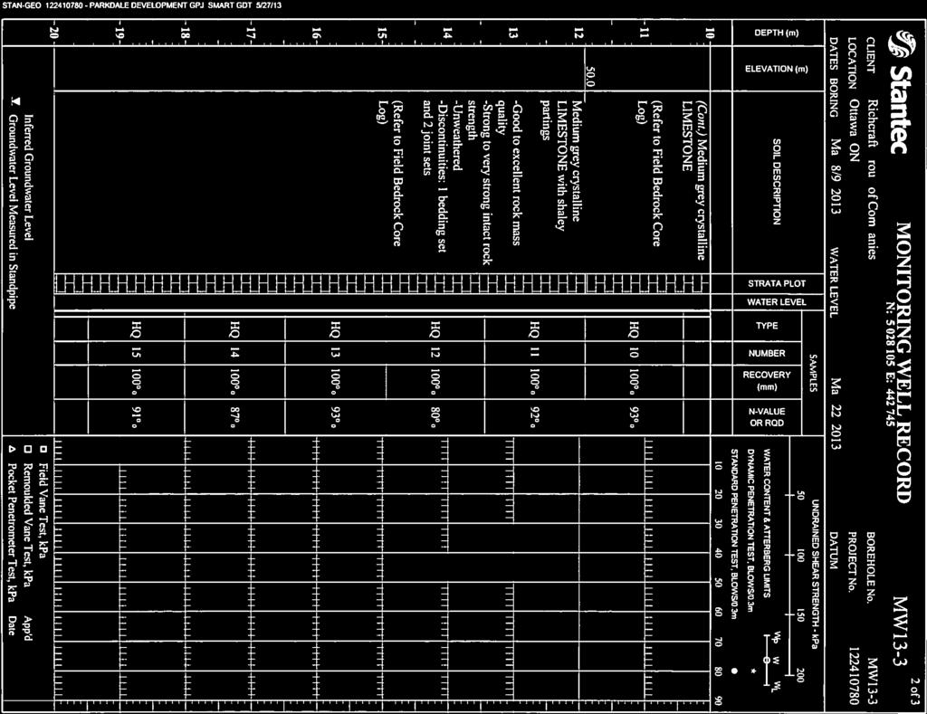
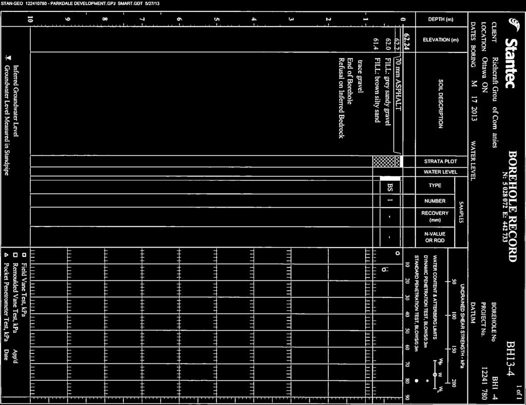
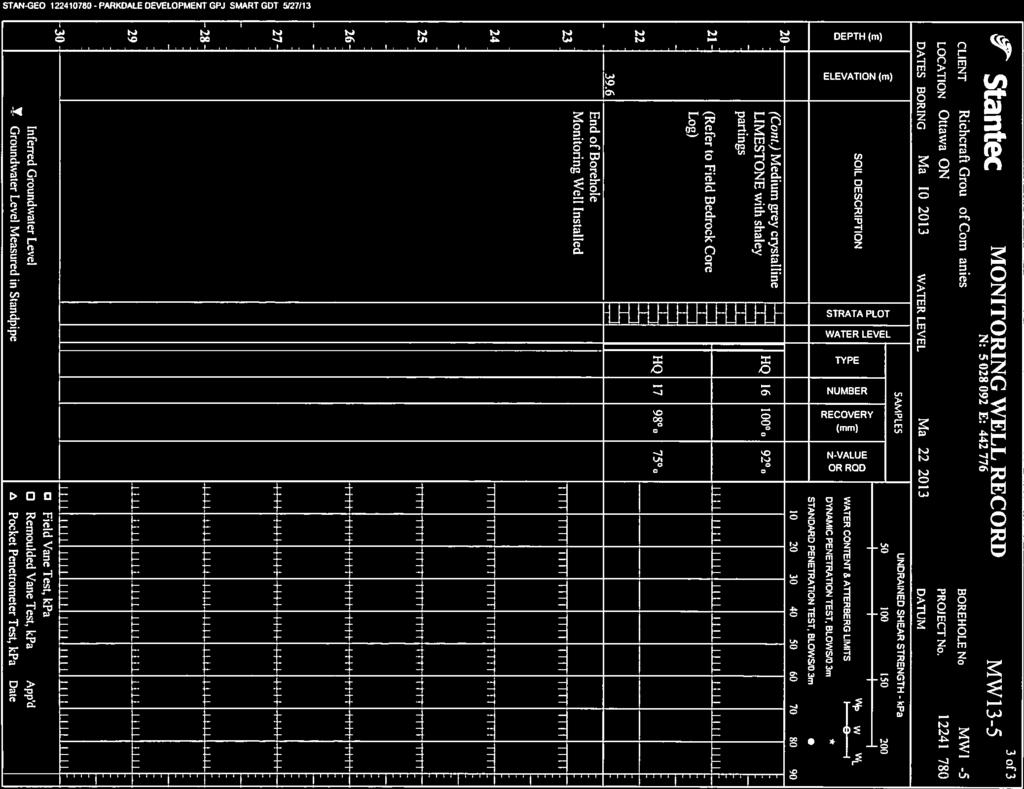
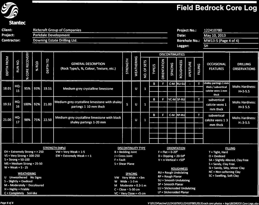
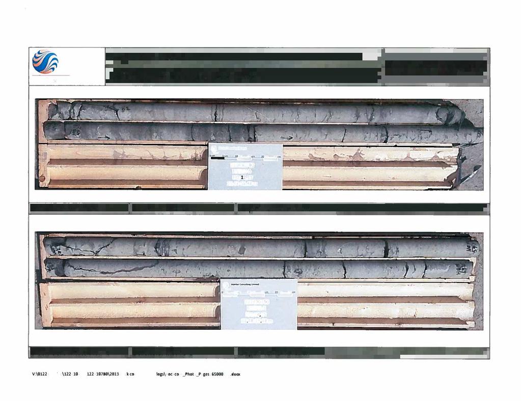
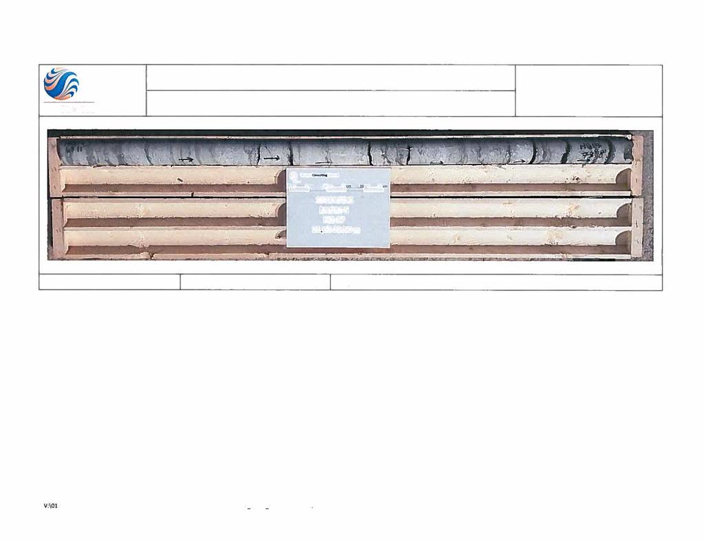
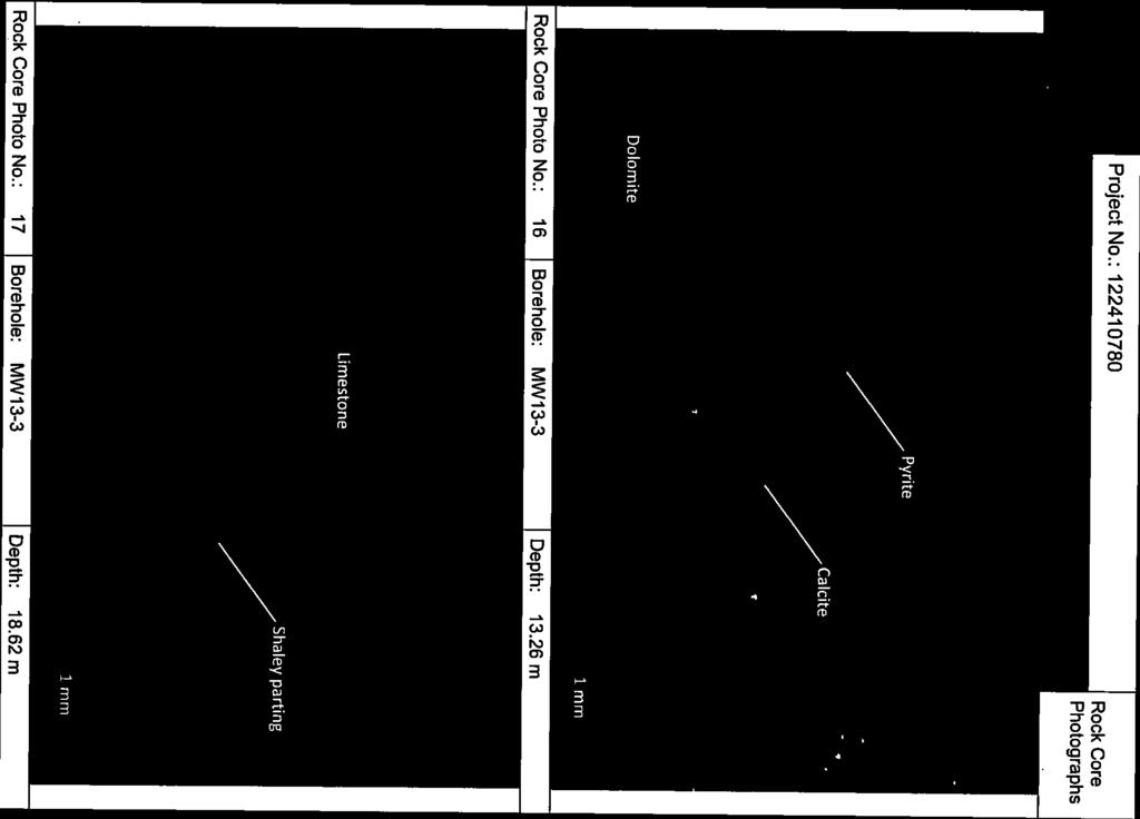
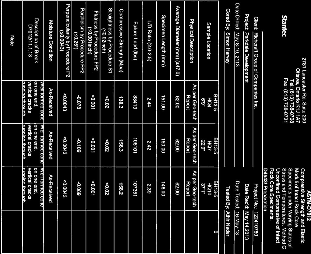
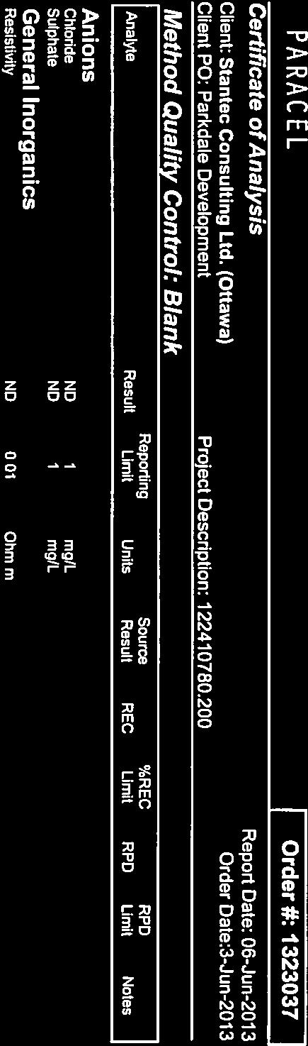
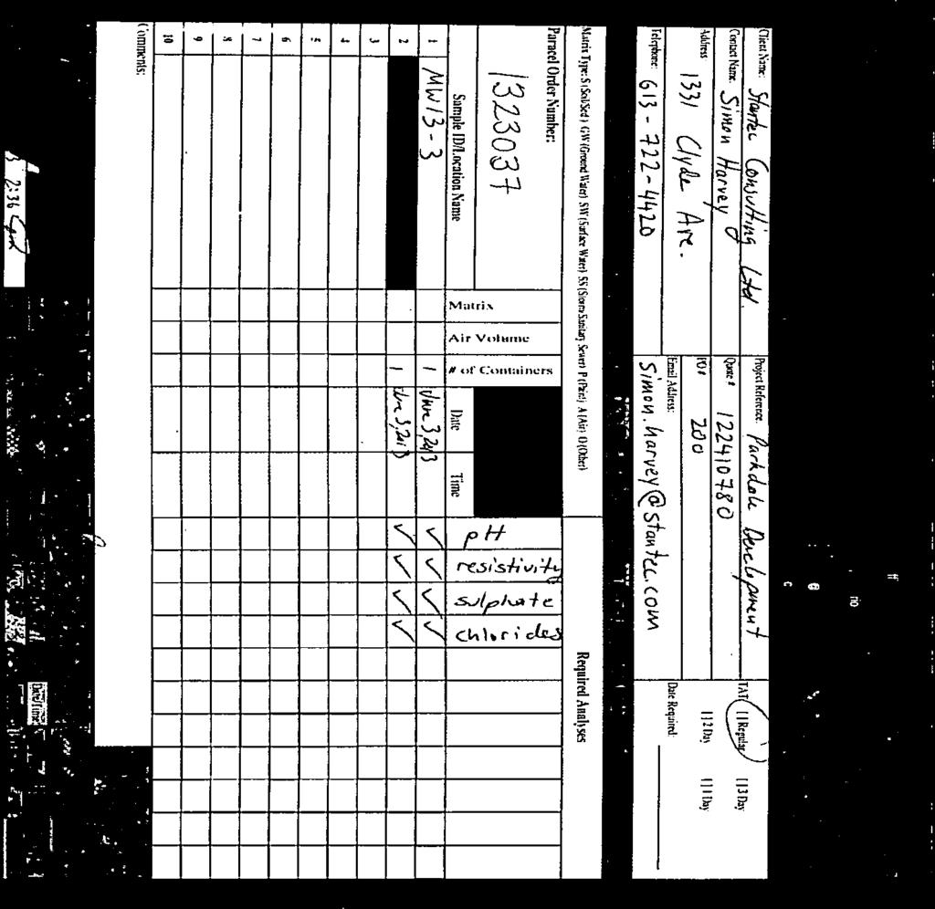
6 FINAL GEOTECHNICAL REPORT June 2013 were submitted to Paracel Laboratories Ltd. to measure ph, resistivity, chlorides, and sulphate content. Results of this testing are shown on the Borehole Records in Appendix C and laboratory test results in Appendix D. Samples will be stored for a period of one (1) month after issuance of this report unless otherwise directed by the client. 5.0 Results of Investigation 5.1 SUBSURFACE INFORMATION The subsurface conditions observed in the boreholes are presented in detail on the Borehole Records, Field Core Logs, and Bedrock Core Photos in Appendix C. An explanation of the symbols and terms used to describe the Borehole Records is also provided in Appendix C. In general, the observed stratigraphy consisted of fill material underlain by shallow bedrock. A general overview of the soil, rock and groundwater conditions encountered in the boreholes is provided below Surficial Materials Asphalt was encountered at the surface of BH13-4 and MW13-5. The asphalt varied from 50 to 70 mm in thickness. Fill materials were observed in all the boreholes and varied from 0.6 m to 0.7 m in thickness. Fill material generally consisted of sandy gravel to gravelly sand, with the exception of a distinct secondary, basal layer of fill observed in BH13-4 consisting of silty sand. The moisture content of fill materials ranged from 3% to 13% Bedrock Bedrock generally consisted of unweathered medium grey crystalline limestone of the Middle Ordovician Bobcaygeon Formation with pervasive dark grey shaley partings. A zone of heavily weathered limestone bedrock was encountered overlying intact, unweathered limestone bedrock in BH13-1, MWs13-3, and 13-5, at depths ranging from 0.7 and 0.8 m below ground surface. The thickness of the heavily weathered layer ranged from 0.3 to 1.0 m. Intact, unweathered limestone bedrock was encountered in all boreholes at depths ranging from 0.8 to 1.7 m below ground surface. The moisture content of the weathered bedrock ranged from 4% to 29%. Occasional features of the limestone included stylolites, calcite veins and vugs, calcite-healed dipping to subvertical fractures, and shaley partings in sections of bedrock where the partings are not pervasive. A large section of medium grey crystalline limestone without pervasive shaley partings was encountered from 1.7 to 11.9 m below ground surface in MW13-3. A dolomitized 3
7 FINAL GEOTECHNICAL REPORT June 2013 bed was encountered in MW13-3 from 13.1 to 13.6 m below ground surface with pyrite and calcite replacement features. The bedrock had three discontinuity sets; 1 bedding set and two joint sets. The bedding set had a very close to wide spacing and a generally flat orientation. Bedding discontinuity surfaces were generally oxidized to tight, with occasional swelling, soft clay filling. The joint sets were subvertical to dipping and were encountered relatively infrequently in the cored rock samples. One subvertical joint encountered in MW13-5 was infilled with coarse calcite crystals, and had a 7 mm aperture. Due to their infrequent occurrence, the spacing of the dipping and subvertical joint sets is indeterminate. Generally bedrock quality was good to excellent; however, the top portion (down to 5.9 m and 2.9 m in MWs13-3 and 13-5, respectively) was observed to be of very poor to fair quality. The Rock Quality Designation (RQD) varied from 0% to 100%. The unconfined compressive strength of the rock, which is summarized below in Table 5.1, ranged from 74.6 MPa to MPa, indicating a strong to very strong intact rock strength. Rock core logs and photos are shown in Appendix C. Table 5-1: Unconfined Compressive Strength of Rock Cores Borehole Depth (m) Unconfined Compressive Strength (MPa) MW13-3 MW A double-packer test was conducted in MW13-3 on May 9, 2013 following its complete advancement to determine the hydraulic conductivity of the of the limestone rock mass. Hydraulic conductivity values ranged from 1.27x10⁻⁷ to 2.47x10⁻⁶ m/s, corresponding to semipervious, fractured bedrock. The results are summarized in Table
8 FINAL GEOTECHNICAL REPORT June 2013 Table 5-2: Packer Test Results Summary Test Interval Average hydraulic Test Interval Minimum k Maximum k Test No. Elevation (m) conductivity, k Depth (m) (m/s) (m/s) (m/s) x x x x x x x x x GROUNDWATER Groundwater was measured by means of monitoring wells installed in MWs 13-3 and Groundwater was measured on May 22, At MW13-3, the groundwater level was measured at 8.5 m (elev. 53.4m) below ground surface. At MW13-5, the groundwater was measured at 8.7 m (elev. 53.4m) below ground surface. Fluctuation in the groundwater level due to seasonal variations or in response to a particular precipitation event should be anticipated. 6.0 Discussion and Recommendations The following geotechnical issues should be considered during design activities: Conventional spread footings founded on bedrock are appropriate for the design of the multi-storey building at this site. Groundwater was encountered at depths within the proposed depth of construction. It is anticipated that surface water run-off and groundwater can be controlled with sump and pump methods during construction. The bedrock on this site consists of limestone with a measured unconfined compressive strength ranging between 75 MPa to 158 MPa, which suggests strong to very strong rock. The soluble sulphate concentrations show that a low degree of sulphate attack is expected for concrete in contact with soil and groundwater. Type GU Portland Cement should therefore be suitable for use in concrete at this site. The recommended Site Classification for Seismic Site Response for the site is Site Class A in accordance with 2006 Ontario Building Code. 6.1 SITE GRADING AND PREPARATION Restrictions to raising the grades at this site are not anticipated due to the granular nature of the surficial soil and shallow bedrock depth Building Footprint Footings should be founded on sound bedrock. Exposed bedrock surfaces should be free of loose bedrock, soil, water, bedrock irregularities, bedrock pinnacles and sloping surfaces. Hand 5
9 FINAL GEOTECHNICAL REPORT June 2013 cleaning and pressure washing of the bearing areas to remove any loose materials will be required to achieve the recommended geotechnical resistance. Temporary frost protection should be provided for all footings if construction is carried out under winter conditions. Prepared subgrade surfaces should be inspected by experienced geotechnical personnel prior to placement of either Structural Fill or concrete. Structural Fill should conform to the requirements of Ontario Provincial Standard Specification (OPSS) Granular A. Structural Fill placed beneath building should contain no recycled materials such as concrete or asphalt. It should be compacted in lifts no thicker than 300 mm to at least 100% Standard Proctor Maximum Dry Density (SPMDD). This material should be tested and approved by a Geotechnical Engineer prior to delivery to the site. Earth removals should be inspected by a geotechnical engineer to ensure that all unsuitable materials are removed prior to placement of fill or concrete. Inspection and testing services will be critical to ensure that all fill and concrete used is suitable and is placed competently Paved Areas All vegetation, topsoil, existing asphalt and other deleterious material should be removed from beneath pavement areas. The subgrade should be proof rolled in the presence of geotechnical personnel. All soft areas revealed during proof rolling or subgrade inspections should be excavated to a maximum depth of 500 mm and replaced with compacted OPSS Granular B Type II. 6.2 FOUNDATIONS The foundations for the proposed building may be supported on spread footings provided that the foundation preparation work described in Section 6.1 above is carried out. Spread footings should be placed on clean undisturbed sound bedrock. Table 6-1 provides Geotechnical Resistances for shallow foundations on bedrock. Table 6-1: Geotechnical Resistance for Foundations on Bedrock Foundation Type Footing Width (m) Geotechnical Resistance, ULS, (kpa) Strip Footing 1.0 to 3.0 4,500 Square Footing 1.0 to 3.0 5,500 The factored geotechnical bearing resistance at ultimate limit states (ULS) incorporates a resistance factor of 0.5. The settlement of foundations founded on bedrock is expected to be negligible. The factored geotechnical resistance at ULS for footings founded on bedrock will govern, since failure within the bedrock mass is likely to occur before the serviceability limit state (SLS) deformation of 25 mm total settlement is realized. 6
10 FINAL GEOTECHNICAL REPORT June 2013 The design frost depth is 1.8 m. All exterior spread footings and footings for unheated structures should be protected from frost action by a minimum soil cover of 1.8 m or equivalent insulation. Perimeter footings should be protected by a minimum soil cover of 1.5 m or equivalent insulation. Perimeter footings and interior footings within 1.5 m of perimeter walls of heated structures should be protected by a minimum soil cover of 1.5 m or equivalent insulation. Where proposed footings have insufficient soil cover for frost protection, the use of insulation will be required. The base of all footing excavations should be inspected by a geotechnical engineer prior to placing concrete to confirm the design geotechnical resistance and to ensure that there is no disturbance of the founding soils. Where construction is undertaken during winter conditions, all footing subgrades should be protected from freezing. Foundation walls and columns should be protected against heave due to soil adfreeze. 6.3 SEISMIC SITE CLASSIFICATION Existing V S30 measurements around the study site were reviewed to determine the site class according to the 2006 Ontario Building Code. The measurements were obtained from the Geological Survey of Canada Surficial Boreholes for the National Capital Area. The data is accessible through the Carleton University website called the Interactive Surface Geography Map for the City of Ottawa. The selected boreholes are illustrated in Drawing No. 3 in Appendix B and the corresponding shear wave velocity information is shown in Table 6.2. This table provides the average shear wave velocity in top 30 m for the studied sites (V s30 ). Based on V s30 values, the recommended site classification for seismic site response for the building is Site Class A in accordance with Table A of the 2006 Ontario Building Code. Table 6-2: Shear Wave Velocity Information of Selected Boreholes Borehole Name Borehole ID Bedrock Bedrock Velocity Range V Depth (m) s30 (m/sec) (m/sec) a UGE b UGE c UGE The location of the proposed building and known faults were evaluated. The location of the nearest faults are shown in Drawing No. 4 in Appendix B. The drawing indicates that the proposed building is not located on a fault. 6.4 GROUNDWATER CONTROL The groundwater level was measured at elevation 53.4 m within both monitoring wells, MWs 13-3 and The proposed below grade parking levels will be below the groundwater level. 7
11 FINAL GEOTECHNICAL REPORT June 2013 The design of the below grade parking levels should consider the groundwater level. The below grade levels could be designed as a waterproof structure designed to resist the build up of hydrostatic pressure. Alternatively, a drainage system (perforated pipe) could be provided around the exterior perimeter of the building and the foundation walls backfilled with free draining granular material such as OPSS Granular B Type II. A second alternative includes the use of a proprietary drainage board in conjunction with the perimeter drainage system with the walls backfilled with OPSS Select Subgrade Material (SSM). The drainage system should be connected to a frost free outlet. An underfloor drainage should also be provided. The subdrains should be founded at least 400 mm below the underside of the floor slab and should be connected to a frost free outlet. If subdrains are proposed, the floor slab should be supported on a 400 mm thick layer of clear stone for drainage. The underfloor drainage system and perimeter drainage system should be connected to separate outlets. 6.5 PIPE BEDDING AND BACKFILL Bedding for utilities should be placed in accordance with the pipe design requirements. It is recommended that a minimum of 150 mm to 200 mm of OPSS Granular A be placed below the pipe invert as bedding material. Granular pipe backfill placed above the invert should consist of Granular A material. A minimum of 300 mm vertical and side cover should be provided. These materials should be compacted to at least 95% of SPMDD. Backfill for service trenches in landscaped areas may consist of excavated material replaced and compacted in lifts. Where the service trenches extend below paved areas, the trench should be backfilled with OPSS SSM from the top of the pipe cover to within 1.2 m of the proposed pavement surface, placed in lifts and compacted to at least 95% of SPMDD. The material used within the upper 1.2 m and below the subgrade line should be similar to that exposed in the trench walls to prevent differential frost heave, placed in lifts and compacted to at least 95% of SPMDD. Different abutting materials within this zone will require a 3 horizontal to 1 vertical frost taper in order to minimize the effects of differential frost heaving. Excavations for catch basins and manholes should be backfilled with compacted granular material. A 3 horizontal to 1 vertical frost taper should be built within the upper 1.2 m. The joints between catch basin or manhole sections must be wrapped with non-woven geotextile. It should be noted that reuse of the site generated material will be highly dependent on the material s moisture content at time of placement. Backfill should be compacted in lifts not exceeding 300 mm. 8
12 FINAL GEOTECHNICAL REPORT June TEMPORARY EXCAVATIONS AND BACKFILLING Excavations in Soil The shallow sandy gravel to gravelly sand, and silty sand fill (maximum encountered thickness of 0.7 m) present at the site is considered Type 3 soil in accordance with the Occupational Health and Safety Act (OHSA) and Regulations for Construction Projects. Temporary excavations in the overburden may be supported or should be sloped at 1 horizontal to 1 vertical from the base of the excavation and as per the requirements of OHSA. Alternatively, sheet piling or other support methods will be required. Excavations should be inspected regularly for signs of instability and flattened as required. The excavation support system should be designed to resist loads from traffic and foundations from adjacent structures Excavations in Bedrock Drilling and blasting and hoe ramming techniques will be required to excavate bedrock. Temporary excavation in bedrock may be carried out at near vertical slopes, provided the trench sides are cleared of loose rock prior to workers entering the trench. If the bedrock is overly fractured such that the loose rock cannot be entirely removed, a temporary rock catchment system such as a wire mesh system should be used. The catchment system should be designed to contain and/or prevent loose rock particles from falling on workers within the excavation. Bedrock excavation sidewalls adjacent to existing building foundations should be supported to ensure the stability of the existing buildings Groundwater Groundwater was encountered during this geotechnical investigation within the depths of the anticipated excavations. Packer tests were conducted to determine the hydraulic conductivity of the limestone bedrock. Hydraulic conductivity values ranged from 1.27x10⁻⁷ to 2.47x10⁻⁶ m/s, corresponding to semipervious, fractured bedrock. It is expected that dewatering of the excavations will be possible using conventional sump and pump techniques. It should be noted that groundwater elevations fluctuate seasonally. Dewatering of the excavation is not anticipated to cause settlement of soils due to groundwater lowering in the vicinity of the site. 6.7 LATERAL EARTH PRESSURES ON SHORING SYSTEMS AND BASEMENT WALLS Earth pressures will need to be considered in the design of shoring systems for temporary excavations during construction and for basement walls. Table 6-3 gives the coefficients of lateral earth pressure for shoring systems and basement walls. These values are based on the assumption that a horizontal back slope will be utilized behind the shoring system and wall. 9
13 FINAL GEOTECHNICAL REPORT June 2013 Static Lateral Earth Pressures For walls that are designed to allow rotation, active earth pressure may be used for design. For rigidly tied and unyielding structures, the at-rest earth pressure should be used for design. The unfactored soil parameters provided in Table 6-3 may be used for design of walls with a horizontal backfill. The effects of compaction should be accounted for by applying a compaction surcharge. The total active (P A ), passive (P P ) and at-rest (P O ) thrusts can be calculated using the following equations P A = ½ K a γ H 2 P P = ½ K p γ H 2 P O = ½ K o γ H 2 where H is the height of the wall and γ is the unit weight of the backfill soil. Preliminary values for K a, K p, K o and γ are provided below. The thrust acts at a point one third up the height of the wall. Table 6-3: Lateral Earth Pressure Parameters Parameter On Site Fill OPSS Granular A OPSS Granular B Type II Unit Weight (kn/m 3 ) Angle of Internal Friction, Φ Coefficient of Passive Earth Pressure, K p Coefficient of at Rest Earth Pressure, K o Coefficient of Active Earth Pressure, K a Seismic Lateral Earth Pressures Seismic earth pressures may be calculated using the parameters detailed in Table 6-4 below. The total active and passive thrusts under seismic loading conditions can be calculated using the following equations: P AE = ½ K AE γ H 2 (1 - k V ) P PE = ½ K PE γ H 2 (1 - k V ) where: K AE = active earth pressure coefficient (combined static and seismic) K PE = passive earth pressure coefficient (combined static and seismic) H = height of wall k h = horizontal acceleration coefficient k v = vertical acceleration coefficient γ = total unit weight of soil 10
14 FINAL GEOTECHNICAL REPORT June 2013 For this site, the following design parameters were used to develop the recommended K AE and K PE values. A yielding wall was assumed. Zonal Acceleration Ratio, A or PGA 0.42 Horizontal Acceleration Coefficient, k h 0.21 Vertical Acceleration Coefficient, k v 0.14 Horizontal Backslope to Wall 0 Vertical Back of Wall 0 The k h value above corresponds to half of the A value for yielding walls. The k v value corresponds to 0.67 of the k h value. The angle of friction between the soil and the wall has been set at 0 to provide a conservative estimate. Table 6-4: Seismic Lateral Earth Pressure Parameters (Yielding Wall) Material K AE Height of Application of P AE from base as a ratio of wall height, (H) K PE Height of Application of P PE from base as a ratio of wall height, (H) φ (friction angle) Unit Weight (kn/m 3 ) OPSS Granular A OPSS Granular B Type II In-Situ Fills If the wall is designed as a non-yielding wall it could be designed based on values obtained from the Wood (1973) method; ΔP eq = γh 2 a h g F p ΔP eq γ H : Steady state dynamic trust : Bulk unit weight of soil : Height of wall (m) g : Gravity (m/s 2 ) a h F p : Amplitude of harmonic base acceleration : Dimensionless trust factor at ν=0.5 h eq = ΔM eq ΔP eq 0.63H 11
15 FINAL GEOTECHNICAL REPORT June SLIDING RESISTANCE Sliding resistance can be calculated using the following unfactored friction coefficients, outlined in Table 6-5. Table 6-5: Unfactored Friction Coefficients Condition Unfactored Friction Coefficient Between Concrete and Structural Fill 0.55 Between Concrete and Clean Bedrock ROCK ANCHORS Rock anchors could be used to ensure stability of temporary shoring system and resist uplift forces. For the design of rock anchors extending into bedrock, the following design parameters may be considered for the rock mass. A rock to grout working bond stress of 1000 kpa may be used for holes grouted with nonshrink grout having a minimum compressive strength of 30 MPa. The minimum fixed anchor length (i.e. the length over which the rock to grout bond stress is developed) should be no less than 3 m. The unbonded length of anchor should be equal to the height of the rock cone and less half the bonded length. To ensure against the possibility of a rock mass failure, the following design parameters should be used: Submerged unit weight of rock = 16 kn/m 3 A 90 (apex angle) failure cone with the apex located at the midpoint of the bonded length as shown on the sheet titled Rock Anchor: Resistance to Rock Mass Failure in Appendix E. The bond stress used by the contractor for design should be confirmed by full scale testing of anchors FOUNDATION BACKFILL Backfill within the footprint of the proposed buildings should consist of OPSS Granular A compacted to 100% SPMDD. Exterior foundation backfill should consist of a material meeting the requirements of OPSS Select Subgrade Material (SSM). Reference is made to Section 6.4 regarding additional comments for foundation wall backfill. Exterior foundation backfill shall be placed in lifts no thicker than 300 mm and compacted using suitable compaction equipment to at least 95% of SPMDD. Care should be taken immediately adjacent to the foundation walls to avoid over-compaction of the soil which could result in damage to the walls. 12
16 FINAL GEOTECHNICAL REPORT June CEMENT TYPE AND CORROSION POTENTIAL Two representative groundwater samples were submitted to Paracel Laboratories Ltd. in Ottawa, Ontario, for ph, chloride, sulphate and resistivity testing. The test results are summarized in Table 6-6. Table 6-6: ph, Sulphate, Chloride and Resistivity Analysis Results Borehole No. ph Sulphate (µg/g) Resistivity (0.01 ohm.m) Chloride (µg/g) MW MW The soluble sulphate ranges from µg/g. Soluble sulphate concentrations less than 1000 µg/g generally indicate that a low degree of sulphate attack is expected for concrete in contact with soil and groundwater. Type GU Portland Cement should therefore be suitable for use in concrete at this site. The ph, resistivity and chloride concentration provide an indication of the degree of corrosiveness of the sub-surface environment. The soil ph was which is within what is considered the normal range for soil ph of 5.5 to 9.0. The ph levels of the tested soil do not indicate a highly corrosive environment. The test results provided in the Table 6.5 can be used to aid in the selection of coatings and corrosion protection systems for buried steel objects PAVEMENT STRUCTURE RECOMMENDATIONS It has been assumed that the parking areas will be used mostly by passenger vehicles and the access roads will be used by delivery trucks and fire vehicles. The subgrade in paved areas should be prepared as described in Section 6.1 above. The following minimum pavement structures are recommended: Table 6-7: Recommended Pavement Design Heavy Duty Parking Access Material Roads Standard Duty Parking Area SP 12.5 Asphaltic Concrete 40 mm 50 mm SP 19 Asphaltic Concrete 50 mm - Granular Base Course, OPSS Granular A 150 mm 150 mm Granular Subbase Course, OPSS Granular B Type II 400 mm 300 mm It is estimated that the service life prior to major rehabilitation for the above pavement structures is 20 years provided they are properly maintained. The pavement surface and the underlying subgrade should be graded to direct runoff water towards suitable drainage. All granular materials should be tested and approved by a geotechnical engineer prior to delivery to the site. Both base and subbase materials should be compacted to at least 100% SPMDD. Asphalt should be compacted to at least 97% Marshal bulk density. 13
17 FINAL GEOTECHNICAL REPORT June 2013 It is recommended that the lateral extent of the subbase and base layers not be terminated in a vertical fashion immediately behind the curb line. A taper with a grade of 5 horizontal to 1 vertical is recommended in the subgrade line to minimize differential frost heave problems under sidewalks VIBRATIONS MONITORING AND PRE-CONSTRUCTION SURVEYS The required construction activities for the proposed building will generate some vibrations that will be perceptible to nearby residents. The vibrations are expected to be greatest during bedrock excavation by blasting/mechanical methods. It is recommended that pre-construction surveys of all structures be carried out in accordance with OPSS 120 General Specifications for the Use of Explosives. It is recommended that construction vibrations generally be limited to a maximum peak particle velocity as outlined in OPSS 120. Should there be structures in the area sensitive to vibrations, more stringent specifications should be developed by a vibration specialist. For instance, the particle velocity should be limited to 10 mm/sec if there is any historic building in the area. Vibration monitoring should be carried out prior to and throughout the construction period. No blasting should be carried out within a distance of 200 m from any water storage reservoir, pumping station, water works transformer station or water storage tank without prior approval by the owner of the facility. 14


18
19 FINAL GEOTECHNICAL REPORT June 2013 APPENDIX A Statement of General Conditions

20 STATEMENT OF GENERAL CONDITIONS USE OF THIS REPORT: This report has been prepared for the sole benefit of the Client or its agent and may not be used by any third party without the express written consent of Stantec Consulting Ltd. and the Client. Any use which a third party makes of this report is the responsibility of such third party. BASIS OF THE REPORT: The information, opinions, and/or recommendations made in this report are in accordance with Stantec Consulting Ltd. s present understanding of the site specific project as described by the Client. The applicability of these is restricted to the site conditions encountered at the time of the investigation or study. If the proposed site specific project differs or is modified from what is described in this report or if the site conditions are altered, this report is no longer valid unless Stantec Consulting Ltd. is requested by the Client to review and revise the report to reflect the differing or modified project specifics and/or the altered site conditions. STANDARD OF CARE: Preparation of this report, and all associated work, was carried out in accordance with the normally accepted standard of care in the state or province of execution for the specific professional service provided to the Client. No other warranty is made. INTERPRETATION OF SITE CONDITIONS: Soil, rock, or other material descriptions, and statements regarding their condition, made in this report are based on site conditions encountered by Stantec Consulting Ltd. at the time of the work and at the specific testing and/or sampling locations. Classifications and statements of condition have been made in accordance with normally accepted practices which are judgmental in nature; no specific description should be considered exact, but rather reflective of the anticipated material behavior. Extrapolation of in situ conditions can only be made to some limited extent beyond the sampling or test points. The extent depends on variability of the soil, rock and groundwater conditions as influenced by geological processes, construction activity, and site use. VARYING OR UNEXPECTED CONDITIONS: Should any site or subsurface conditions be encountered that are different from those described in this report or encountered at the test locations, Stantec Consulting Ltd. must be notified immediately to assess if the varying or unexpected conditions are substantial and if reassessments of the report conclusions or recommendations are required. Stantec Consulting Ltd. will not be responsible to any party for damages incurred as a result of failing to notify Stantec Consulting Ltd. that differing site or subsurface conditions are present upon becoming aware of such conditions. PLANNING, DESIGN, OR CONSTRUCTION: Development or design plans and specifications should be reviewed by Stantec Consulting Ltd., sufficiently ahead of initiating the next project stage (property acquisition, tender, construction, etc), to confirm that this report completely addresses the elaborated project specifics and that the contents of this report have been properly interpreted. Specialty quality assurance services (field observations and testing) during construction are a necessary part of the evaluation of sub-subsurface conditions and site preparation works. Site work relating to the recommendations included in this report should only be carried out in the presence of a qualified geotechnical engineer; Stantec Consulting Ltd. cannot be responsible for site work carried out without being present.
21 FINAL GEOTECHNICAL REPORT June 2013 APPENDIX B Key Plan Borehole Location Plan V S30 Measurement Location Plan Fault Location Plan
22


23

24


25
26 FINAL GEOTECHNICAL REPORT June 2013 APPENDIX C Symbols and Terms Used on Borehole Records Borehole Records Field Core Logs Bedrock Core Photos

27


28


29

30

31


32

33
34

35


36
37

38

39

40

41

42

43

44
45


46


47


48


49

50


51
52
53

54


55
56 FINAL GEOTECHNICAL REPORT June 2013 APPENDIX D Laboratory Test Results

57

58
59

60


61


62


63
64

65


66

67


68
69 FINAL GEOTECHNICAL REPORT June 2013 APPENDIX E Rock Anchor: Resistance to Rock Mass Failure

70
Final Geotechnical Report Multi-Level Building at 159, 163 and 167 Parkdale Ave. Ottawa, ON
 Final Geotechnical Report Multi-Level Building at 159, 163 and 167 Parkdale Ave. Ottawa, ON Prepared for: Richcraft Group of Companies 2280 St. Laurent Blvd, Ottawa, ON K1G 4K1 Prepared by: Stantec Consulting
February 22, 2016 AG File No
 Ainley Graham & Associates Limited 1-50 Grant Timmins Drive, Kingston, Ontario, K7M 8N2 Tel: (343) 266-0002 Fax: (343) 266-0028 E-mail Kingston@ainleygroup.com February 22, 2016 AG File No. 15062-1 Ministry
GEOTECHNICAL REPORT CBSA Facility Redevelopment Thousand Islands International Crossing Lansdowne, Ontario
 GEOTECHNICAL REPORT CBSA Facility Redevelopment Thousand Islands International Crossing Lansdowne, Ontario Prepared For: The Federal Bridge Corporation Limited SPL Project No.: 10001084 Report Date: January
Updated Subsurface Investigation Block A Heritage Hills Development 124 Battersea Crescent Ottawa, Ontario
 Updated Subsurface Investigation Block A Heritage Hills Development 124 Battersea Crescent Ottawa, Ontario Submitted to: Brigil Homes 98 rue Lois Gatineau, Quebec J8Y 3R7 Updated Subsurface Investigation
Subsurface Investigation Proposed Commercial Building 528 March Road Ottawa, Ontario
 Subsurface Investigation Proposed Commercial Building 8 March Road Ottawa, Ontario Houle Chevrier Engineering Ltd. 80 Wescar Lane Ottawa, Ontario K0A L0 www.hceng.ca Submitted to: Broccolini Construction
Geotechnical Investigation Proposed Retirement Residence Goulbourn Forced Road Ottawa, Ontario
 REPORT February 205 REPORT ON Geotechnical Investigation Proposed Retirement Residence Goulbourn Forced Road Ottawa, Ontario Submitted to: Dan Roach, AIA Hawthorne Development LLC c/o Lenity Architecture
Geotechnical Investigation Proposed Residential Development 99 Beechwood Avenue Ottawa, Ontario
 REPORT REPORT ON Geotechnical Investigation Proposed Residential Development 99 Beechwood Avenue Ottawa, Ontario Submitted to: Claridge Homes 210 Gladstone Avenue, Suite 2001 Ottawa, Ontario K2P 0Y6 Report
GEOTECHNICAL INVESTIGATION REPORT
 GEOTECHNICAL INVESTIGATION REPORT DH 1404-05 ACCOMODATE SPECIALIZED EQUIPMENT, DWYER HILL TRAINING CENTRE RICHMOND, ONTARIO Prepared for: Defence Construction Canada (DCC) Date: February 2016 Report No.:
Ottawa, June 5, Ms. Monica Dashwood Director of Development Viva Retirement Communities 3845 Bathurst Street, Suite 206 Toronto, Ontario M3H 3N2
 REPORT: T020846-A2 VIVA RETIREMENT COMMUNITIES Geotechnical Investigation Report Five-Story Retirement Home Strandherd Drive and Tartan Drive Ottawa, Ontario June 5, 2013 Ottawa, June 5, 2013 Ms. Monica
Geotechnical Investigation Proposed Retirement Residence Timberwalk Ottawa, Ontario
 September 6 REPORT ON Geotechnical Investigation Proposed Retirement Residence Timberwalk Ottawa, Ontario Submitted to: Claridge Homes Corporation - Gladstone Avenue Ottawa, ON KP Y6 REPORT Report Number:
Date: April 2, 2014 Project No.: Prepared For: Mr. Adam Kates CLASSIC COMMUNITIES 1068 E. Meadow Circle Palo Alto, California 94303
 City of Newark - 36120 Ruschin Drive Project Draft Initial Study/Mitigated Negative Declaration Appendix C: Geologic Information FirstCarbon Solutions H:\Client (PN-JN)\4554\45540001\ISMND\45540001 36120
ATTACHMENT A PRELIMINARY GEOTECHNICAL SUMMARY
 ATTACHMENT A PRELIMINARY GEOTECHNICAL SUMMARY Kevin M. Martin, P.E. KMM Geotechnical Consultants, LLC 7 Marshall Road Hampstead, NH 0384 603-489-6 (p)/ 603-489-8 (f)/78-78-4084(m) kevinmartinpe@aol.com
Chapter 12 Subsurface Exploration
 Page 12 1 Chapter 12 Subsurface Exploration 1. The process of identifying the layers of deposits that underlie a proposed structure and their physical characteristics is generally referred to as (a) subsurface
patersongroup 1.0 Geotechnical Desktop Review Consulting Engineers April 18, 2017 PG4080-LET.01
 patersongroup April 18, 2017 PG080-LET.01 2015-2017 RR Ltd 311 Richmond Road, Suite 203 Ottawa, ON K1Z 6X3 Attention: Subject: Mr. Jonah Bonn Geotechnical Desktop Review Proposed Drive-Thru Lanes 2015-2017
ROCK EXCAVATION (GRADING) OPSS 206 INDEX
 OPSS 206 INDEX") 206-2 - OPSS 206 INDEX 206-2.1 GENERAL 206-2.1.1 Classification of Rock Materials 206-2.1.2 Tender Items 206-2.1.3 Other Excavation Tender Items 206-2.1.4 Specifications 206-2.1.5 Special Provisions 206-2.1.6
206-2 - OPSS 206 INDEX 206-2.1 GENERAL 206-2.1.1 Classification of Rock Materials 206-2.1.2 Tender Items 206-2.1.3 Other Excavation Tender Items 206-2.1.4 Specifications 206-2.1.5 Special Provisions 206-2.1.6
DRAFT GEOTECHNICAL INVESTIGATION REPORT
 DRAFT GEOTECHNICAL INVESTIGATION REPORT PROPOSED NEW SEWER INSTALLATION CITY OF CLARENCE-ROCKLAND, ONTARIO Prepared for: City of Clarence-Rockland 151-03483-00 Date: July 2015 WSP Canada Inc. 500 Greber
ENCE 3610 Soil Mechanics. Site Exploration and Characterisation Field Exploration Methods
 ENCE 3610 Soil Mechanics Site Exploration and Characterisation Field Exploration Methods Geotechnical Involvement in Project Phases Planning Design Alternatives Preparation of Detailed Plans Final Design
SITE INVESTIGATION 1
 SITE INVESTIGATION 1 Definition The process of determining the layers of natural soil deposits that will underlie a proposed structure and their physical properties is generally referred to as site investigation.
Gotechnical Investigations and Sampling
 Gotechnical Investigations and Sampling Amit Prashant Indian Institute of Technology Gandhinagar Short Course on Geotechnical Investigations for Structural Engineering 12 14 October, 2017 1 Purpose of
KDOT Geotechnical Manual Edition. Table of Contents
 KDOT Geotechnical Manual 2007 Edition The KDOT Geotechnical Manual is available two volumes. Both volumes are very large electronic (pdf) files which may take several minutes to download. The table of
Civil Engineering, Surveying and Environmental Consulting WASP0059.ltr.JLS.Mich Ave Bridge Geotech.docx
 2365 Haggerty Road South * Canton, Michigan 48188 P: 734-397-3100 * F: 734-397-3131 * www.manniksmithgroup.com August 29, 2012 Mr. Richard Kent Washtenaw County Parks and Recreation Commission 2330 Platt
Geotechnical Investigation Report
 Geotechnical Investigation Report Proposed Salt Storage Shed Majestic Hills Drive Hamilton Township, Ontario Hamilton Township 7 Pido Road Peterborough Ontario K9J 6X7 Canada 568 0 Report No June 08 Table
Slope Stability Assessment Proposed Development 4401 Fallowfield Road Lands Ottawa, Ontario Rev-02
 REPORT August 2014 REPORT ON Slope Stability Assessment Proposed Development 4401 Fallowfield Road Lands Ottawa, Ontario Submitted to: DCR Phoenix Homes 18 Bentley Avenue Ottawa, Ontario K2E 6T8 Report
patersongroup Geotechnical Investigation Proposed Industrial Building 1670 Comstock Road Ottawa, Ontario Prepared For Simluc Contractors Limited
 Geotechnical Engineering Environmental Environmental Engineering Engineering Hydrogeology Hydrogeology Geological Engineering Geological Engineering Materials Testing Materials Testing Building Science
Geotechnical Engineering Subsurface Investigation Report 13-SI-7-BH-1Page)
") Geotechnical Engineering Subsurface Investigation Report 3-SI-7-BH-Page) Canadian Shield Avenue, Kanata, ON, K2K H4 Abstract: This report present the findings of the geotechnical investigation completed
Geotechnical Engineering Subsurface Investigation Report 3-SI-7-BH-Page) Canadian Shield Avenue, Kanata, ON, K2K H4 Abstract: This report present the findings of the geotechnical investigation completed
Eastgate Parking Lot Geotechnical Investigation
 Eastgate Parking Lot Geotechnical Investigation Cambium Reference No.: 336- March 4, 24 Prepared for: City of Peterborough Cambium Inc. P.O. Box 325 52 Hunter Street East, Peterborough Ontario, K9H G5
Prepared for. Mr. Denis A. Verdon 445, Wilson Road Rockland, Ontario K4K 1K7
 GEOTECHNICAL INVESTIGATION Proposed Verdon Subdivision Part of Lot 16, Concession I (Old Survey) Geographic Township of Clarence Now City of Clarence-Rockland Prepared for Mr. Denis A. Verdon 445, Wilson
General. DATE December 10, 2013 PROJECT No TO Mary Jarvis Urbandale/Riverside South Development Corporation
 DATE December 10, 201 PROJECT No. 10-1121-0260- TO Mary Jarvis Urbandale/Riverside South Development Corporation CC Justin Robitaille, Urbandale Jonathan Párraga, J.L. Richards & Associates Limited FROM
SLOPE STABILITY EVALUATION AND ACCEPTANCE STANDARDS
 INFORMATION BULLETIN / PUBLIC - BUILDING CODE REFERENCE NO.: LAMC 98.0508 Effective: 1-26-84 DOCUMENT NO. P/BC 2002-049 Revised: 11-1-02 Previously Issued As: RGA #1-84 SLOPE STABILITY EVALUATION AND ACCEPTANCE
SOIL INVESTIGATION REPORT. PROPOSED HOUSING DEVELOPMENT PROJECT Coral Spring, Trelawny, Jamaica.
 SOIL INVESTIGATION REPORT PROPOSED HOUSING DEVELOPMENT PROJECT Coral Spring, Trelawny, Jamaica. Prepared for: FCS Consultants 7a Barbados Avenue Kingston 5, Jamaica Prepared by: NHL Engineering Limited
patersongroup Geotechnical Investigation Proposed Elementary School 2300 Esprit Drive Ottawa, Ontario Prepared For Ottawa Catholic School Board
 Geotechnical Engineering Environmental Engineering Hydrogeology Geological Engineering Materials Testing Building Science Proposed Elementary School 300 Esprit Drive Archaeological Services Prepared For
Geotechnical Engineering Study, Conifer Senior High School Football Field Improvements, Conifer, Colorado
 2390 South Lipan Street Denver, CO 80223 phone: (303) 742-9700 fax: (303) 742-9666 email: kadenver@kumarusa.com www.kumarusa.com Office Locations: Denver (HQ), Colorado Springs, Fort Collins, and Frisco,
patersongroup Mineral Aggregate Assessment 3119 Carp Road Ottawa, Ontario Prepared For Mr. Greg LeBlanc March 7, 2014 Report: PH2223-REP.
 Geotechnical Engineering Environmental Engineering group Hydrogeology Geological Engineering Archaeological Studies Materials Testing 3119 Carp Road Prepared For Mr. Greg LeBlanc March 7, 2014 Paterson
Geotechnical Engineering Subsurface Investigation Report 13-SI-7-BH-1BPage)
") Geotechnical Engineering Subsurface Investigation Report 3-SI-7-BH-BPage) Canadian Shield Avenue, Kanata, ON, K2K H4 Abstract: This report present the findings of the geotechnical investigation completed
Geotechnical Engineering Subsurface Investigation Report 3-SI-7-BH-BPage) Canadian Shield Avenue, Kanata, ON, K2K H4 Abstract: This report present the findings of the geotechnical investigation completed
patersongroup memorandum 1.0 Field Investigation consulting engineers
 consulting engineers memorandum to: KDSA Development Corporation - Ms. Susan Anglin - susananglin6@gmail.com re: Pavement Structure Recommendations - Shady Maple Road Proposed Braeburn Estates Residential
GEOTECHNICAL INVESTIGATION MULTIPLE STREETS AND ROADS F18-INF CITY OF CLARENCE-ROCKLAND
 GEOTECHNICAL INVESTIGATION MULTIPLE STREETS AND ROADS F18-INF-2018-012 CITY OF CLARENCE-ROCKLAND Prepared for: The City of Clarence-Rockland Attn: Mr. Alain Beaulieu, Coordinator, Capital Projects 1560
Geotechnical Investigation Juneau Seawalk - Taku Fisheries to Miner s Wharf Juneau, Alaska DM&A Job No
 Duane Miller & Associates 5821 Arctic Boulevard, Suite A Anchorage, AK 99518-1654 (907) 644-3200 Fax 644-0507 Arctic & Geotechnical Engineering May 4, 2006 Tetra Tech/KCM, Inc. 1971 First Avenue Seattle,
FROST HEAVE. GROUND FREEZING and FROST HEAVE
 FROST HEAVE The temperature of soils near the ground surface reflects the recent air temperatures. Thus, when the air temperature falls below 0 C (32 F) for extended periods, the soil temperature drops
IAEA SAFETY STANDARDS Geotechnical Aspects of Site Evaluation and Foundations in NPPs, NS-G-3.6
 IAEA SAFETY STANDARDS Geotechnical Aspects of Site Evaluation and Foundations in NPPs, NS-G-3.6 Regional Workshop on Volcanic, Seismic, and Tsunami Hazard Assessment Related to NPP Siting Activities and
patersongroup 1.0 Field Observations Consulting Engineers January 20, 2014 File: PG3145-LET.01 City View Curling Club 50 Capilano Drive
 January 0, 04 File: P345-LET.0 City View Curling Club 50 Capilano Drive Ottawa, Ontario KE 64 Attention: Ms. Cheryl Carroll Consulting Engineers 54 Colonnade Road South Ottawa, Ontario KE 7J5 Tel: (63)
Boreholes. Implementation. Boring. Boreholes may be excavated by one of these methods: 1. Auger Boring 2. Wash Boring 3.
 Implementation Boreholes 1. Auger Boring 2. Wash Boring 3. Rotary Drilling Boring Boreholes may be excavated by one of these methods: 4. Percussion Drilling The right choice of method depends on: Ground
SLOPE STABILITY EVALUATION AND ACCEPTANCE STANDARDS
 INFORMATION BULLETIN / PUBLIC - BUILDING CODE REFERENCE NO.: LABC 7006.3, 7014.1 Effective: 01-01-2017 DOCUMENT NO.: P/BC 2017-049 Revised: 12-21-2016 Previously Issued As: P/BC 2014-049 SLOPE STABILITY
Converse Consultants Geotechnical Engineering, Environmental & Groundwater Science, Inspection & Testing Services
 Converse Consultants Geotechnical Engineering, Environmental & Groundwater Science, Inspection & Testing Services Ms. Rebecca Mitchell Mt. San Antonio College Facilities Planning & Management 1100 North
10. GEOTECHNICAL EXPLORATION PROGRAM
 Geotechnical site investigations should be conducted in multiple phases to obtain data for use during the planning and design of the tunnel system. Geotechnical investigations typically are performed in
Liquefaction and Foundations
 Liquefaction and Foundations Amit Prashant Indian Institute of Technology Gandhinagar Short Course on Seismic Design of Reinforced Concrete Buildings 26 30 November, 2012 What is Liquefaction? Liquefaction
APPENDIX E SOILS TEST REPORTS
 Otsego County, NY Site Work Specifications APPENDIX E SOILS TEST REPORTS Blue Wing Services, Inc. July 1, 2010 Blue Wing Services May 20, 2010 Page 2 the site, was not made available to Empire at this
Conseil des écoles catholiques du Centre-Est (CECCE)
") Conseil des écoles catholiques du Centre-Est (CECCE) Geotechnical Investigation Type of Document Final Project Name Proposed Addition to New Horizon Jeunesse chool 349 Olmstead treet, Ottawa, Ontario Project
Conseil des écoles catholiques du Centre-Est (CECCE) Geotechnical Investigation Type of Document Final Project Name Proposed Addition to New Horizon Jeunesse chool 349 Olmstead treet, Ottawa, Ontario Project
Reference No S072 APRIL 2012
 A REPORT TO SOLMAR DEVELOPMENT CORP. A PRELIMINARY SOIL INVESTIGATION FOR PROPOSED SUBDIVISION DEVELOPMENT NORTHEAST OF SIDEROAD 5 AND 0 LINE TOWN OF ERIN Reference No. 202-S072 APRIL 202 DISTRIBUTION
Appendix H. Geotechnical Investigation Report. Krosno Creek Flood Reduction Project PROJECT FILE REPORT CITY OF PICKERING
 Krosno Creek Flood Reduction Project PROJECT FILE REPORT CITY OF PICKERING Appendix H Geotechnical Investigation Report TMIG THE MUNICIPAL INFRASTRUCTURE GROUP LTD Report on Geotechnical Investigation
GEOTECHNICAL INVESTIGATION REPORT
 GEOTECHNICAL INVESTIGATION REPORT SOIL INVESTIGATION REPORT FOR STATIC TEST FACILITY FOR PROPELLANTS AT BDL, IBRAHIMPATNAM. Graphics Designers, M/s Architecture & Engineering 859, Banjara Avenue, Consultancy
Northern Colorado Geotech
 PRELIMINARY GEOTECHNICAL ENGINEERING REPORT PROPOSED CECIL FARMS DEVELOPMENT WELD COUNTY ROAD 7, BETWEEN ROADS 7 AND 7 SEVERANCE, COLORADO NORTHERN COLORADO GEOTECH PROJECT NO. 0-6 APRIL 0, 06 Prepared
OVERVIEW OF ER DRILLING IN EARTH EMBANKMENT DAMS AND
 OVERVIEW OF ER 1110-1-1807 DRILLING IN EARTH EMBANKMENT DAMS AND 255 255 255 237 237 237 0 0 0 217 217 217 LEVEES 163 163 163 200 200 200 131 132 122 239 65 53 80 119 27 110 135 120 Requirements and Processes
LIMITED SUPPLEMENTARY GEOTECHNICAL INVESTIGATION REPORT FOR PROPOSED ROAD, DRAINAGE, AND SIDEWALK IMPROVEMENTS IN THE VILLAGE OF NEWBURY, ONTARIO
 LIMITED SUPPLEMENTARY GEOTECHNICAL INVESTIGATION REPORT FOR PROPOSED ROAD, DRAINAGE, AND SIDEWALK IMPROVEMENTS IN THE VILLAGE OF NEWBURY, ONTARIO Prepared for: CIMA+ #900, 101 Frederick Street Kitchener,
Pierce County Department of Planning and Land Services Development Engineering Section
 Page 1 of 7 Pierce County Department of Planning and Land Services Development Engineering Section PROJECT NAME: DATE: APPLICATION NO.: PCDE NO.: LANDSLIDE HAZARD AREA (LHA) GEOLOGICAL ASSESSMENT REPORT
Geotechnical Investigation Proposed Richmond Home Hardware Addition 6379 Perth Street Richmond, Ontario
 Geotechnical Investigation Proposed Richmond Home Hardware Addition 6379 Perth Street Richmond, Ontario Houle Chevrier Engineering Ltd. 180 Wescar Lane Ottawa, Ontario K0A 1L0 www.hceng.ca Submitted to:
REFERENCE NO S135 NOVEMBER 2015
 A REPORT TO DUNPAR DEVELOPMENTS INC. A SOIL INVESTIGATION FOR PROPOSED RESIDENTIAL DEVELOPMENT 020, 024, 032, 042, 048 AND 052 6 TH LINE, TOWN OF OAKVILLE REFERENCE NO. 505-S35 NOVEMBER 205 DISTRIBUTION
patersongroup Consulting Engineers April 20, 2010 File: PG1887-LET.01R Novatech Engineering Consultants Suite 200, 240 Michael Cowpland Drive
 patersongroup April 20, 2010 File: PG1887-LET.01R Novatech Engineering Consultants Suite 200, 240 Michael Cowpland Drive Ottawa, Ontario K2M 1P6 Attention: Mr. Adam Thompson Consulting Engineers 28 Concourse
CITY OF CAPE CORAL NORTH 2 UTILITIES EXTENSION PROJECT CONTRACT 3
 GEOTECHNICAL REPORT CITY OF CAPE CORAL NORTH UTILITIES EXTENSION PROJECT CONTRACT City of Cape Coral Procurement Division Cultural Park Boulevard, nd Floor Cape Coral, FL ISSUED FOR BID VOLUME of GEOTECHNICAL
Geotechnical Engineering Report
 Geotechnical Engineering Report Turner Turnpike Widening Bridge D Bridge Crossing: South 209 th West Avenue Creek County, Oklahoma June 1, 2016 Terracon Project No. 04155197 Prepared for: Garver, LLC Tulsa,
Module 9 : Foundation on rocks. Content
 FOUNDATION ON ROCKS Content 9.1 INTRODUCTION 9.2 FOUNDATION TYPES ON ROCKS 9.3 BEARING CAPCITY- SHALLOW FOUNDATION 9.3.1 Ultimate bearing capacity 9.3.2 Safe bearing pressure 9.3.3 Estimation of bearing
GEOTECHNICAL ENGINEERING II. Subject Code : 06CV64 Internal Assessment Marks : 25 PART A UNIT 1
 GEOTECHNICAL ENGINEERING II Subject Code : 06CV64 Internal Assessment Marks : 25 PART A UNIT 1 1. SUBSURFACE EXPLORATION 1.1 Importance, Exploration Program 1.2 Methods of exploration, Boring, Sounding
Slope Stability Evaluation Ground Anchor Construction Area White Point Landslide San Pedro District Los Angeles, California.
 Slope Stability Evaluation Ground Anchor Construction Area White Point Landslide San Pedro District Los Angeles, California Submitted To: Mr. Gene Edwards City of Los Angeles Department of Public Works
B805 TEMPORARY EROSION AND SEDIMENT CONTROL MEASURES - OPSS 805
 B805 MEASURES - OPSS 805 805.1 GENERAL Construction activities frequently remove protective cover and expose soil to accelerated rates of erosion. Sediments generated thereby can be conveyed via runoff
Geotechnical Investigation. Trent University Arena Complex Nassau Mills Road and Pioneer Road Peterborough, Ontario. City of Peterborough
 Geotechnical Investigation Trent University Arena Complex Nassau Mills Road and Pioneer Road Peterborough, Ontario City of Peterborough September, 0 Pido Road, Unit, Peterborough, Ontario, Canada KJ X
Internal C Unit Dilatanc y
 2 Grimsby Sub was not at any time definitively established. The preliminary analysis provided by Thurber Engineering Ltd indicates the slope should be stable with a factor of safety of 1.23 for a deep
Converse Consultants Geotechnical Engineering, Environmental & Groundwater Science, Inspection & Testing Services
 Converse Consultants Geotechnical Engineering, Environmental & Groundwater Science, Inspection & Testing Services July 27, 2017 Ms. Rebecca Mitchell Mt. San Antonio College Facilities Planning & Management
Geotechnical Investigation Proposed Commercial Development 1095 Algoma Road Ottawa, Ontario
 February 2016 REPORT ON Geotechnical Investigation Proposed Commercial Development 1095 Algoma Road Ottawa, Ontario Submitted to: 1095 Algoma Road Inc. 1294 Algoma Road Ottawa, Ontario K1B 3W8 REPORT Report
APPENDIX A GEOTECHNICAL REPORT
 The City of Winnipeg Bid Opportunity No. 529-2017 Template Version: C420170317 - RW APPENDIX A GEOTECHNICAL REPORT Quality Engineering Valued Relationships KGS Group 2017 Industrial Street Rehabilitation
Early Exploration Permit Activity Information
 Early Exploration Permit Activity Information Activities That Require an Early Exploration Permit: Line cutting that is a width greater than 1.5 metres Mechanized stripping of a total surface area of greater
June 9, R. D. Cook, P.Eng. Soils Engineer Special Services Western Region PUBLIC WORKS CANADA WESTERN REGION REPORT ON
 PUBLIC WORKS CANADA WESTERN REGION REPORT ON GEOTECHNICAL INVESTIGATION PROPOSED MARTIN RIVER BRIDGE MILE 306.7 MACKENZIE HIGHWAY Submitted by : R. D. Cook, P.Eng. Soils Engineer Special Services Western
Central Queensland Coal Project Appendix 4b Geotechnical Assessment. Environmental Impact Statement
 Central Queensland Coal Project Appendix 4b Geotechnical Assessment Environmental Impact Statement GEOTECHNICAL ASSESSMENT OF OPEN CUT MINING ADJACENT TO THE BRUCE HIGHWAY, CENTRAL QUEENSLAND COAL PROJECT
An Introduction to Field Explorations for Foundations
 An Introduction to Field Explorations for Foundations J. Paul Guyer, P.E., R.A. Paul Guyer is a registered mechanical engineer, civil engineer, fire protection engineer and architect with over 35 years
Manual on Subsurface Investigations National Highway Institute Publication No. FHWA NHI Federal Highway Administration Washington, DC
 Manual on Subsurface Investigations National Highway Institute Publication No. FHWA NHI-01-031 Federal Highway Administration Washington, DC Geotechnical Site Characterization July 2001 by Paul W. Mayne,
The results of KCB s site inspection observations and our recommendations for further work are presented herein.
 July 14, 2015 Central Region 401, 4902 51 Street Red Deer, Alberta T4N 6K8 Mr. Tony Penney, P.Eng. Construction Engineer Dear Mr. Penney: June 25, 2015 Site Inspection Report The above site was visited
REPORT ON SUPPLEMENTAL GEOTECHNICAL INVESTIGATION ABBOTT FERNBANK HOLDINGS INC. PROPERTY FERNBANK ROAD OTTAWA, ONTARIO.
 8 escar Lane R.R. Carp, Ontario, KA L Tel: (6) 86- Fax: (6) 86-97 www.hceng.ca REPT ON SUPPLEMENTAL GEOTECHNICAL INVESTIGATION ABBOTT FERNBANK HOLDINGS INC. PROPERTY FERNBANK ROAD OTTAA, ONTARIO Submitted
APPENDIX D. Acheson Zone 4 Reservoir Expansion Geotechnical Investigation. Parkland County Acheson, AB. Project number: (433)
") APPENDIX D Acheson Zone 4 Reservoir Expansion Geotechnical Investigation Acheson, AB Project number: 60586018 (433) November 21, 2018 Acheson Zone 4 Reservoir Expansion Geotechnical Investigation Statement
APPENDIX D Acheson Zone 4 Reservoir Expansion Geotechnical Investigation Acheson, AB Project number: 60586018 (433) November 21, 2018 Acheson Zone 4 Reservoir Expansion Geotechnical Investigation Statement
Submitted to: Clublink Corporation ULC & Clublink Holdings Limited Dufferin Street King City, ON L4M 6Y1
 October 0 PRELIMINARY GEOTECHNICAL INVESTIGATION Glen Abbey Golf Club Redevelopment Oakville, Ontario Submitted to: Clublink Corporation ULC & Clublink Holdings Limited 7 Dufferin Street King City, ON
Geotechnical Engineering Report
 Geotechnical Engineering Report Turner Turnpike Widening Polecat Creek Bridge (Bridge A) June 1, 2016 Terracon Project No. 04155197 Prepared for: Garver, LLC Prepared by: Terracon Consultants, Inc. TABLE
Hydraulic uplift forces on basements subject to liquefaction
 Hydraulic uplift forces on basements subject to liquefaction N.S. Luxford Babbage Consultants Ltd 2014 NZSEE Conference ABSTRACT: As a result of the 22 February 2011 earthquake in Christchurch a building
GEOTECHNICAL INVESTIGATION REPORT INFRASTRUCTURE PVT LTD
 GEOTECHNICAL INVESTIGATION REPORT Client : TAEIN CONSTRUCTION & INFRASTRUCTURE PVT LTD Office address : Flat No.104, A -Wing,1st floor,gloria Park, Paranjape Scheme, Bavdhan Khurd, Chandni Chowk, Pune
PRINCIPLES OF GEOTECHNICAL ENGINEERING
 PRINCIPLES OF GEOTECHNICAL ENGINEERING Fourth Edition BRAJA M. DAS California State University, Sacramento I(T)P Boston Albany Bonn Cincinnati London Madrid Melbourne Mexico City New York Paris San Francisco
Geotechnical Report Site Investigation and Design Recommendations Ottawa Community Housing Project 3225 Uplands Drive
 Geotechnical Report Site Investigation and Design Recommendations Ottawa Community Housing Project 3225 Uplands Drive Prepared for: Atelier 292 Architect Inc. 292 Main Street Ottawa, Ontario K1S 1E1 Prepared
Geotechnical Investigation Bow Ridge Subdivision Phase 3 Cochrane, Alberta
 Geotechnical Investigation Bow Ridge Subdivision Phase 3 Cochrane, Alberta FINAL Prepared for: The Town of Cochrane 101 Ranchehouse Road Cochrane, Alberta Prepared by: Stantec Consulting Ltd. Calgary,
APPENDIX F CORRELATION EQUATIONS. F 1 In-Situ Tests
 APPENDIX F 1 APPENDIX F CORRELATION EQUATIONS F 1 In-Situ Tests 1. SPT (1) Sand (Hatanaka and Uchida, 1996), = effective vertical stress = effective friction angle = atmosphere pressure (Shmertmann, 1975)
REPORT OF PRELIMINARY GEOTECHNICAL EXPLORATION
 REPORT OF PRELIMINARY GEOTECHNICAL EXPLORATION ENKA INTERMEDIATE SCHOOL Sand Hill Road Candler, North Carolina Prepared For: BUNCOMBE COUNTY SCHOOLS Prepared By: AMEC ENVIRONMENT & INFRASTRUCTURE, INC.
316 SOMERSET STREET GEOTECHNICAL REPORT
 316 SOMERSET STREET GEOTECHNICAL REPORT Project No.: CP-17-0637 Prepared for: TC United Group 800 Industrial Ave. Unit 9 Ottawa, ON, K1G 4B8 Prepared by: McIntosh Perry 115 Walgreen Rd, R.R. 3 Carp, ON
Early Exploration Plan Activity Information
 Early Exploration Plan Activity Information Activities That Require an Early Exploration Plan: Line cutting that is a width of 1.5 metres or less; Geophysical surveys on the ground requiring the use of
CENTRAL REGION GEOHAZARDS RISK ASSESSMENT SITE INSPECTION FORM
 SITE NUMBER AND NAME C55 H861:02 Slide LEGAL DESCRIPTION NW 14-40-14-W4 CENTRAL REGION GEOHAZARDS RISK ASSESSMENT SITE INSPECTION FORM HIGHWAY & KM NAD 83 COORDINATES N 5811217 E 437291 PREVIOUS INSPECTION
HISTORY OF CONSTRUCTION FOR EXISTING CCR SURFACE IMPOUNDMENT PLANT GASTON ASH POND 40 CFR (c)(1)(i) (xii)
(1)(i) (xii)") HISTORY OF CONSTRUCTION FOR EXISTING CCR SURFACE IMPOUNDMENT PLANT GASTON ASH POND 40 CFR 257.73(c)(1)(i) (xii) (i) Site Name and Ownership Information: Site Name: E.C. Gaston Steam Plant Site Location:
HISTORY OF CONSTRUCTION FOR EXISTING CCR SURFACE IMPOUNDMENT PLANT GASTON ASH POND 40 CFR 257.73(c)(1)(i) (xii) (i) Site Name and Ownership Information: Site Name: E.C. Gaston Steam Plant Site Location:
SHEET PILE WALLS. Mehdi Mokhberi Islamic Azad University
 SHEET PILE WALLS Mehdi Mokhberi Islamic Azad University Lateral Support In geotechnical engineering, it is often necessary to prevent lateral soil movements. Tie rod Anchor Sheet pile Cantilever retaining
UNDP HARARE HOSPITAL PROPOSED NATPHARM WAREHOUSE
 UNDP HARARE HOSPITAL PROPOSED NATPHARM WAREHOUSE January 17 2016 TO CARRY OUT IN-SITU SOIL SURVEY, LABORATORY TESTS AND GEOTECHNICAL REPORTING. GEOTECHNICAL INVESTIGATIONS REPORT 1 2 Re: GEOTECHNICAL INVESTIGATIONS
R.M.HARW & ASSOCIATES LTD. GEOTECHNICAL INVESTIGATION PROPOSED BRIDGE SITE. HELAVA CREEKl MILE MACKENZIE HIGHWAY E-2510 OCTOBER 16, 1973
 El R.M.HARW & ASSOCIATES LTD. GEOTECHNICAL INVESTIGATION PROPOSED BRIDGE SITE HELAVA CREEKl MILE 616.4 MACKENZIE HIGHWAY E-2510 OCTOBER 16, 1973 R,M,HARDV & ASSOCIATES LTD. CONSULTING ENGINEERING & TESTING
 Rock Slope Analysis Small and Large Scale Failures Mode of Failure Marklands Test To establish the possibility of wedge failure. Plane failure is a special case of wedge failure. Sliding along
Reference No S013. OCTOBER 2014 (Revision of Report dated May 2012)
") A REPORT TO SHORELINE TOWERS INC. A SOIL INVESTIGATION FOR PROPOSED CONMINIUM WITH 3-LEVEL UNDERGROUND PARKING PART OF LOTS 377, 378 AND 379 BEHIND 2313 AND 2323 LAKE SHORE BOULEVARD WEST CITY OF TORONTO
A REPORT TO SHORELINE TOWERS INC. A SOIL INVESTIGATION FOR PROPOSED CONMINIUM WITH 3-LEVEL UNDERGROUND PARKING PART OF LOTS 377, 378 AND 379 BEHIND 2313 AND 2323 LAKE SHORE BOULEVARD WEST CITY OF TORONTO
FINAL REPORT, GEOTECHNICAL INVESTIGATION, NORTHWEST RIVER BRIDGE RECONSTRUCTION, TERRA NOVA NATIONAL PARK, NL. File No:
 FINAL REPORT, GEOTECHNICAL INVESTIGATION, NORTHWEST RIVER BRIDGE RECONSTRUCTION, TERRA NOVA NATIONAL PARK, NL File No: 6847 Prepared for: Harbourside Engineering Consultants 9 Waverly Road, Suite Dartmouth
 R-1 Conveyor Relocation Project Legend 0 500 1000 1500 ft. This map is a user generated static output from an Internet mapping site and is for general reference only. Data layers that appear on this map
Hydro One (Sept 2014) Hydro One (Sept 2014) Hydro One (Sept 2014)
 Hydro One (Sept 2014) Hydro One (Sept 2014)") TABLE 1 WELL CONSTRUCTION DETAILS MOE WWR No Well ID Location Installation Date Status Easting Coordinates Northing Source Elevation Screened Interval Screened Material Borehole Well Stick-up Ground Top
TABLE 1 WELL CONSTRUCTION DETAILS MOE WWR No Well ID Location Installation Date Status Easting Coordinates Northing Source Elevation Screened Interval Screened Material Borehole Well Stick-up Ground Top
REPORT OF SUBSURFACE EXPLORATION
 REPORT OF SUBSURFACE EXPLORATION GRAND RIVER DAM AUTHORITY HULBERT 69 KV SWITCHING STATION S. 440 Road Hulbert, Cherokee County, Oklahoma ENERCON PROJECT NO. GRDA006 MARCH 7, 2012 PREPARED FOR: C/O ENERCON
SCOPE OF INVESTIGATION Simple visual examination of soil at the surface or from shallow test pits. Detailed study of soil and groundwater to a
 Lecture-5 Soil Exploration Dr. Attaullah Shah 1 Today s Lecture Purpose of Soil Exploration Different methods 1. Test trenches and Pits 2. Auger and Wash Boring 3. Rotary Drilling 4. Geophysical Methods
patersongroup Design for Earthquakes Consulting Engineers May 19, 2016 File: PG3733-LET.01
 patersongroup May 19, 2016 File: PG3733-LET.01 Hydro Ottawa Limited c/o Cresa Toronto 170 University Avenue, Suite 1 Toronto, Ontario M5H 3B3 Attention: Ms. Barbara Wright Consulting Engineers 154 Colonnade