Rectifier Diode Types W3708MC300 to W3708MC350
|
|
|
- Tracy Alexander
- 6 years ago
- Views:
Transcription
 3100-3600 V UNITS OTHER RATINGS MAXIMUM LIMITS IF(AV)M Maximum average forward current, Tsink=55 C, (note 2) 3753 A IF(AV)M Maximum")
1 Date:- 18 th May 2017 Data Sheet Issue:- 2 Rectifier Diode Types W3708MC300 to W3708MC350 Absolute Maximum Ratings VOLTAGE RATINGS MAXIMUM LIMITS VRRM Repetitive peak reverse voltage, (note 1) V VRSM Non-repetitive peak reverse voltage, (note 1) V UNITS OTHER RATINGS MAXIMUM LIMITS IF(AV)M Maximum average forward current, Tsink=55 C, (note 2) 3753 A IF(AV)M Maximum average forward current. Tsink=100 C, (note 2) 2566 A IF(AV)M Maximum average forward current. Tsink=100 C, (note 3) 1476 A IF(RMS)M Nominal RMS forward current, Tsink=25 C, (note 2) 6942 A IF(d.c.) D.C. forward current, Tsink=25 C, (note 4) 5940 A IFSM Peak non-repetitive surge tp=10ms, Vrm=60%VRRM, (note 5) A IFSM2 Peak non-repetitive surge tp=10ms, Vrm 10V, (note 5) A I 2 t I 2 t capacity for fusing tp=10ms, Vrm=60%VRRM, (note 5) A 2 s I 2 t I 2 t capacity for fusing tp=10ms, Vrm 10V, (note 5) A 2 s Tj op Operating temperature range -40 to +160 C Tstg Storage temperature range -55 to +160 C UNITS Notes:- 1) De-rating factor of 0.13% per C is applicable for Tj below 25 C. 2) Double side cooled, single phase; 50Hz, 180 half-sinewave. 3) Cathode side cooled, single phase; 50Hz, 180 half-sinewave. 4) Double side cooled. 5) Half-sinewave, 160 C Tj initial. Data Sheet. Types W3708MC300 to W3708MC350 Page 1 of 9 May, 2017
2 Characteristics PARAMETER MIN. TYP. MAX. TEST CONDITIONS (Note 1) UNITS VFM Maximum peak forward voltage IFM=3000A V VFM Maximum peak forward voltage IFM=11260A V VT0 Threshold voltage V rt Slope resistance mω IRRM Peak reverse current Rated VRRM ma Qrr Recovered charge µc Qra Recovered charge, 50% Chord ITM=1000A, tp=1000µs, di/dt=10a/µs, µc Irm Reverse recovery current Vr=100V A trr Reverse recovery time, 50% chord µs Double side cooled K/W RthJK Thermal resistance, junction to heatsink Anode side cooled K/W Cathode side cooled K/W F Mounting force Note 2 kn Wt Weight 530 g Notes:- 1) Unless otherw ise indicated T j =160 C. 2) For other clamp forces, please consult factory. Data Sheet. Types W3708MC300 to W3708MC350 Page 2 of 9 May, 2017
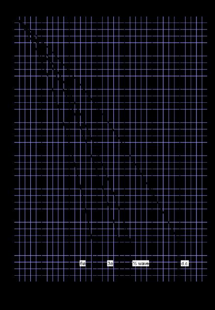
3 Notes on Ratings and Characteristics 1.0 Voltage Grade Table Voltage Grade VRRM VRSM VR V V DC V Extension of Voltage Grades This report is applicable to other voltage grades when supply has been agreed by Sales/Production. 3.0 De-rating Factor A blocking voltage de-rating factor of 0.13%/ C is applicable to this device for Tj below 25 C. 4.0 Snubber Components When selecting snubber components, care must be taken not to use excessively large values of snubber capacitor or excessively small values of snubber resistor. Such excessive component values may lead to device damage due to the large resultant values of snubber discharge current. If required, please consult the factory for assistance. 5.0 Computer Modelling Parameters I AV 5.1 Device Dissipation Calculations 2 VT 0 + VT 0 + = 2 4 ff 2 ff r T 2 r T W AV and: Where VT0=0.958V, rt=0.112mω, R th = Supplementary thermal impedance, see table below and ff = Form factor, see table below. W AV T = R T = T th j max T K Supplementary Thermal Impedance Conduction Angle 6 phase (60 ) 3 phase (120 ) ½ wave (180 ) d.c. Square wave Double Side Cooled Square wave Cathode Side Cooled Sine wave Double Side Cooled Sine wave Cathode Side Cooled Form Factors Conduction Angle 6 phase (60 ) 3 phase (120 ) ½ wave (180 ) d.c. Square wave Sine wave Data Sheet. Types W3708MC300 to W3708MC350 Page 3 of 9 May, 2017
4 5.2 Calculating VF using ABCD Coefficients The on-state characteristic IF vs. V F, on page 6 is represented in two ways; (i) the well established VT0 and rt tangent used for rating purposes and (ii) a set of constants A, B, C, D, forming the coefficients of the representative equation for VF in terms of IF given below: V F = A + B ln ( I F ) + C I F + D I F The constants, derived by curve fitting software, are given below for both hot and cold characteristics. The resulting values for VF agree with the true device characteristic over a current range, which is limited to that plotted. 25 C Coefficients 160 C Coefficients A A B B C C D D Data Sheet. Types W3708MC300 to W3708MC350 Page 4 of 9 May, 2017
5 5.3 D.C. Thermal Impedance Calculation p = n t = p= 1 r r p 1 e t τ p Where p = 1 to n, n is the number of terms in the series and: t = Duration of heating pulse in seconds. r t = Thermal resistance at time t. rp = Amplitude of pth term. τp = Time Constant of rth term. The coefficients for this device are shown in the tables below: D.C. Double Side Cooled Term rp τp Term rp τp Reverse recovery ratings (i) Qra is based on 50% Irm chord as shown in Fig. 1 Fig. 1 (ii) Qrr is based on a 150µs integration time i.e. (iii) K Factor = t t 1 2 Q rr = 150µ s 0 i rr. dt Data Sheet. Types W3708MC300 to W3708MC350 Page 5 of 9 May, 2017


6 Curves Figure 1 Forward characteristics of Limit device Figure 2 Transient thermal impedance Figure 3 Maximum Surge Rating Data Sheet. Types W3708MC300 to W3708MC350 Page 6 of 9 May, 2017


7 Figure 4 Total recovered charge, Qrr Figure 5 Recovered charge, Qra (50% chord) Figure 6 Peak reverse recovery current, Irm Figure 7 Maximum recovery time, trr (50% chord) Data Sheet. Types W3708MC300 to W3708MC350 Page 7 of 9 May, 2017


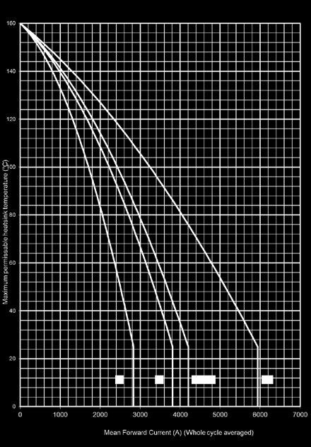
8 Figure 8 Forward current vs. Power dissipation Double Side Cooled Figure 9 Forward current vs. Heatsink temperature Double Side Cooled Figure 10 Forward current vs. Power dissipation Cathode Side Cooled Figure 11 Forward current vs. Heatsink temperature Cathode Side Cooled Data Sheet. Types W3708MC300 to W3708MC350 Page 8 of 9 May, 2017
9 Outline Drawing & Ordering Information 100A353 ORDERING INFORMATION (Please quote 10 digit code as below ) W3708 MC 0 Fixed Type Code Fixed Outline Code Order code: W3708MC V V RRM, 26.3mm clamp height capsule. Voltage code V RRM / Fixed code IXYS Semiconductor GmbH Edisonstraße 15 D Lampertheim Tel: Fax: marcom@ixys.de IXYS Corporation 1590 Buckeye Drive Milpitas CA USA Tel: +1 (408) Fax: +1 (408) sales@ixys.net IXYS UK Westcode Ltd Langley Park Way, Langley Park, Chippenham, Wiltshire, SN15 1GE. Tel: +44 (0) Fax: +44 (0) WSL.sales@w estcode.com IXYS Long Beach, Inc 2500 Mira Mar Avenue Long Beach CA USA Tel: +1 (562) Fax: +1 (562) service@ixyslongbeach.com The information contained herein is confidential and is protected by Copyright. The information may not be used or disclosed except with the written permission of and in the manner permitted by the proprietors Westcode Semiconductors Ltd. IXYS UK Westcode Ltd. In the interest of product improvement, Westcode reserves the right to change specifications at any time without prior notice. Devices with a suffix code (2-letter, 3-letter or letter/digit/letter combination) added to their generic code are not necessarily subject to the conditions and limits contained in this report. Data Sheet. Types W3708MC300 to W3708MC350 Page 9 of 9 May, 2017
10 Data Sheet. Types W3708MC300 to W3708MC350 Page 10 of 9 May, 2017
Rectifier Diode Types W0507YH360 to W0507YH450 Previous Type No.: SW36-45HXC270
 Date:- 6 th March, 214 Data Sheet Issue:- 3 Rectifier Diode Types W57YH36 to W57YH45 Previous Type No.: SW36-45HXC27 Absolute Maximum Ratings VOLTAGE RATINGS MAXIMUM LIMITS V RRM Repetitive peak reverse
Rectifier Diode Types W3270N#200 and W3270N#220 Old Type No.: SW20-22CXC14C
 Date:- 23 October, 213 Data Sheet Issue:- 6 Rectifier Diode Types W327N#2 and W327N#22 Old Type No.: SW2-22CXC14C Absolute Maximum Ratings VOLTAGE RATINGS MAXIMUM LIMITS V RRM Repetitive peak reverse voltage,
Phase Control Thyristor Types N1467NC200 to N1467NC260
 Date:- 31 st July 2012 Data Sheet Issue:- 3 Phase Control Thyristor Types N1467NC200 to N1467NC260 Absolute Maximum Ratings VOLTAGE RATINGS MAXIMUM LIMITS V DRM Repetitive peak off-state voltage, (note
Phase Control Thyristor Types N1075LN180
 Date:- 3 th April, 15 Data Sheet Issue:- 3 Phase Control Thyristor Types Absolute Maximum Ratings VOLTAGE RATINGS MAXIMUM LIMITS V DRM Repetitive peak off-state voltage, (note 1) 18 V V DSM Non-repetitive
Phase Control Thyristor Types N1588NC200 to N1588NC260
 Date:- 2 August 212 Data Sheet Issue:- 2 Phase Control Thyristor Types N1588NC2 to N1588NC26 Absolute Maximum Ratings VOLTAGE RATINGS MAXIMUM LIMITS V DRM Repetitive peak off-state voltage, (note 1) 2-26
Phase Control Thyristor Types N0465WN140 and N0465WN160
 Date:- 4 th June, 214 Data Sheet Issue:- 4 Phase Control Thyristor Types N465WN14 and N465WN16 Absolute Maximum Ratings VOLTAGE RATINGS MAXIMUM LIMITS V DRM Repetitive peak off-state voltage, (note 1)
Phase Control Thyristor Types N2086NC060 to N2086NC100
 Date:- August 1 Data Sheet Issue:- 3 Phase Control Thyristor Types N86NC6 to N86NC1 Absolute Maximum Ratings VOLTAGE RATINGS MAXIMUM LIMITS V DRM Repetitive peak off-state voltage, (note 1) 6-1 V V DSM
Phase Control Thyristor Types N3165HA260 and N3165HA280 Development Type No.: NX450HA260 and NX450HA280
 Date:- 8 th December, 214 Data Sheet Issue:- A1 Phase Control Thyristor Types N3165HA26 and N3165HA28 Development Type No.: NX45HA26 and NX45HA28 Absolute Maximum Ratings VOLTAGE RATINGS MAXIMUM LIMITS
WESTCODE. Rectifier Diode Types W2820V#360 to W2820V#450 Old Type No.: SW36-45C/FXC1100. An IXYS Company. Date:- 9 Jul, Data Sheet Issue:- 1
 WESTCODE An IXYS Company Date:- 9 Jul, 24 Data Sheet Issue:- 1 Rectifier Diode Types W282V#36 to W282V#45 Old Type No.: SW36-45C/FXC11 Absolute Maximum Ratings VOLTAGE RATINGS MAXIMUM LIMITS V RRM Repetitive
WESTCODE. Rectifier Diode Types W1856NC400 to W1856NC500 Old Type No: SW40-50CXC815. An IXYS Company. Date:- 21 Dec, Data Sheet Issue:- 1
 WESTCODE An IXYS Company Date:- 21 Dec, 24 Data Sheet Issue:- 1 Rectifier Diode Types W1856NC4 to W1856NC5 Old Type No: SW4-5CXC815 Absolute Maximum Ratings VOLTAGE RATINGS MAXIMUM LIMITS V RRM Repetitive
WESTCODE. Rectifier Diode Types W1520N#500 to W1520N#600 Old Part No.: SW46-58CXC620. An IXYS Company. Date:- 5 Apr, Data Sheet Issue:- 2
 WESTCODE An IXYS Company Date:- 5 Apr, 26 Data Sheet Issue:- 2 Rectifier Diode Types W152N#5 to W152N#6 Old Part No.: SW46-58CXC62 Absolute Maximum Ratings VOLTAGE RATINGS MAXIMUM LIMITS V RRM Repetitive
WESTCODE. An IXYS Company. Date:- 10 Oct, Data Sheet Issue:- 1
 WESTCODE An IXYS Company Date:- 1 Oct, 26 Data Sheet Issue:- 1 Provisional Data Wespack Rectifier Diode Types W5334MK2-W5334MK22 Previous Type No.: W4987MK2-22 Absolute Maximum Ratings VOLTAGE RATINGS
WESTCODE. An IXYS Company. Date:- 16 Jun, Data Sheet Issue:- 1
 WESTCODE An IXYS Company Date:- 16 Jun, 26 Data Sheet Issue:- 1 Provisional Data Rectifier Diode Type W428##25 to W428##32 Development Type No.: WX171##25-32 Absolute Maximum Ratings VOLTAGE RATINGS MAXIMUM
Dual Diode Water Cooled Modules MD# 950
 Date: 23.5.25 Data Sheet Issue: 2 Dual Diode Water Cooled Modules MD# 95 Absolute Maximum Ratings V RRM V DRM [V] MDD MDA MDK 12 95-12N1W 95-12N1W 95-12N1W 14 95-14N1W 95-14N1W 95-14N1W 16 95-16N1W 95-16N1W
IXYS. Thyristor/Diode Modules MC#500. Date: 13 th Mar Data Sheet Issue: 1. Absolute Maximum Ratings V RRM V DRM [V] MAXIMUM LIMITS
![IXYS. Thyristor/Diode Modules MC#500. Date: 13 th Mar Data Sheet Issue: 1. Absolute Maximum Ratings V RRM V DRM [V] MAXIMUM LIMITS](/thumbs/82/85648543.jpg "IXYS. Thyristor/Diode Modules MC#500. Date: 13 th Mar Data Sheet Issue: 1. Absolute Maximum Ratings V RRM V DRM [V] MAXIMUM LIMITS") Date: 13 th Mar 13 Data Sheet Issue: 1 Absolute Maximum Ratings Thyristor/Diode Modules MC#5 V RRM V DRM [V] 3 5-3io7 5-3io7 5-3io7 5-3io7 36 5-36io7 5-36io7 5-36io7 5-36io7 VOLTAGE RATINGS MAXIMUM LIMITS
Date: 13 th Mar 13 Data Sheet Issue: 1 Absolute Maximum Ratings Thyristor/Diode Modules MC#5 V RRM V DRM [V] 3 5-3io7 5-3io7 5-3io7 5-3io7 36 5-36io7 5-36io7 5-36io7 5-36io7 VOLTAGE RATINGS MAXIMUM LIMITS
IXYS. Thyristor/Diode Modules MC#650. Date: 13 th Mar Data Sheet Issue: 1. Absolute Maximum Ratings V RRM V DRM [V] MAXIMUM LIMITS
![IXYS. Thyristor/Diode Modules MC#650. Date: 13 th Mar Data Sheet Issue: 1. Absolute Maximum Ratings V RRM V DRM [V] MAXIMUM LIMITS](/thumbs/77/76137340.jpg "IXYS. Thyristor/Diode Modules MC#650. Date: 13 th Mar Data Sheet Issue: 1. Absolute Maximum Ratings V RRM V DRM [V] MAXIMUM LIMITS") Date: 13 th Mar 13 Data Sheet Issue: 1 Absolute Maximum Ratings Thyristor/Diode Modules MC#65 V RRM V DRM [V] 4 65-4io7 65-4io7 65-4io7 65-4io7 VOLTAGE RATINGS MAXIMUM LIMITS V DRM Repetitive peak off-state
Date: 13 th Mar 13 Data Sheet Issue: 1 Absolute Maximum Ratings Thyristor/Diode Modules MC#65 V RRM V DRM [V] 4 65-4io7 65-4io7 65-4io7 65-4io7 VOLTAGE RATINGS MAXIMUM LIMITS V DRM Repetitive peak off-state
Phase Control Thyristor Types N4085ZC080 to N4085ZC120 Old Type No.: N1600CH02-12
 Date:- 3 Jan, 23 Data Sheet Issue:- 1 Phase Control Thyristor Types N485ZC8 to N485ZC12 Old Type No.: N16CH2-12 Absolute Maximum Ratings VOLTAGE RATINGS MAXIMUM LIMITS V DRM Repetitive peak off-state voltage,
Phase Control Thyristor Types N2500VC120 to N2500VC160
 WESTCODE Date:- 2 Nov, 21 Data Sheet Issue:- 1 Phase Control Thyristor Types N25VC12 to N25VC16 Absolute Maximum Ratings VOLTAGE RATINGS MAXIMUM LIMITS VDRM Repetitive peak off-state voltage, (note 1)
Thyristor/Diode Modules M## 700 MCC MCD MDC MCA MCK MCDA MDCA
 Date: 27.1.25 Data Sheet Issue: 2 Absolute Maximum Ratings Thyristor/Diode Modules M## 7 V RRM V DRM [V] MCC MCD MDC MCA MCK MCDA MDCA 12 7-12io1W 7-12io1W 7-12io1W 7-12io1W 7-12io1W 7-12io1W 7-12io1W
Thyristor/Diode Modules M## 500 MCC MCD MDC MCA MCK MCDA MDCA
 Date: 19.9.25 Data Sheet Issue: 3 Absolute Maximum Ratings Thyristor/Diode Modules M## 5 V RRM V DRM [V] MCC MCD MDC MCA MCK MCDA MDCA 2 5-2io1 5-2io1 5-2io1 5-2io1 5-2io1 5-2io1 5-2io1 22 5-22io1 5-22io1
Phase Control Thyristor Types N1114LS120 to N1114LS180
 WESTCODE Date:- 6 Feb, 1 Data Sheet Issue:- 1 Phase Control Thyristor Types N1114LS1 to N1114LS18 Absolute Maximum Ratings VOLTAGE RATINGS MAXIMUM LIMITS VDRM Repetitive peak off-state voltage, (note 1)
Phase Control Thyristor Types N3533Z#140 to N3533Z#220 Old Type No.: N1400CH02-20
 WESTCODE An IXYS Company Date:- 18 Sept 27 Data Sheet Issue:- 2 Phase Control Thyristor Types N3533Z#14 to N3533Z#22 Old Type No.: N14CH2-2 Absolute Maximum Ratings VOLTAGE RATINGS MAXIMUM LIMITS V DRM
Symmetrical Gate Turn-Off Thyristor Types S0300SR12Y
 Date: 21 Feb, 2014 Data Sheet Issue:- 2 Symmetrical Gate Turn-Off Thyristor Types bsolute Maximum Ratings MXIMUM VOLTGE RTINGS LIMITS UNITS V DRM Repetitive peak off-state voltage, (note 1) 1200 V V DSM
Phase Control Thyristor Type SKT552/16E
 Date:- 4 Feb 22 Data Sheet Issue:- 3 Absolute Maximum Ratings Phase Control Thyristor Type VOLTAGE RATINGS Symbol Parameter MAXIMUM UNITS V DRM Repetitive peak off-state voltage, (note 1) 16 V V DSM Non-repetitive
Advanced Data Water Cooled Heatsink Type XW180GC34#
 Advanced Data Water Cooled Heatsink Type Characteristics Double side cooling, 2 coolers + 1 Semiconductor Date: - 5 th November, 2009 Data Sheet Issue: - 2 PARAMETER TYP. TEST CONDITIONS UNITS R th (C/W)
Fast Symmetrical Gate Turn-Off Thyristor Type H0700KC14# to H0700KC17#
 Date:- 28 September, 22 Data Sheet Issue:- 2 Fast Symmetrical Gate Turn-Off Thyristor Type H7KC4# to H7KC7# Absolute Maximum Ratings MAXIMUM VOLTAGE RATINGS LIMITS UNITS V DRM Repetitive peak off-state
Rectifier Diode 5SDD 11D2800
 V RSM = 3 V I F(AV)M = 1285 A I F(RMS) = 219 A I FSM = 15 1 3 A V F =.933 V r F =.242 mw Rectifier Diode 5SDD 11D28 Doc. No. 5SYA1166- Okt. 3 Very low on-state losses Optimum power handling capability
5SDF 13H4505. Fast Recovery Diode. Properties. Key Parameters. VRRM = V Enhanced Safe Operating Area. IFAVm = A Industry standard housing
 5SDF 13H455 5SDF 13H455 Fast Recovery Diode Properties Key Parameters Optimized soft recovery characteristics VRRM = 4 5 V Enhanced Safe Operating Area IFAVm = 1 393 A Industry standard housing IFSM =
5SDF 06D2504 Old part no. DM
 Fast Recovery Diode Properties 5SDF 6D254 Old part no. DM 827-62-25 Key Parameters Optimized recovery characteristics V RRM = 2 5 V Industry standard housing I FAVm = 615 A I FSM = 1 A Applications V TO
Blocking Maximum rated values 1) Parameter Symbol Conditions 5SDF 28L4520 Unit Repetitive peak reverse voltage
 Parameter Symbol Conditions 5SDF 28L4520 Unit Repetitive peak reverse voltage") VRRM = 4500 V ast Recovery Diode I(AV)M = 2620 A ISM = 56 10 3 A V0 = 1.10 V r = 0.47 mω VDC-Link = 2800 V 5SD 28L4520 Doc. No. 5SYA1185-03 Jan. 17 Industry standard housing Cosmic radiation withstand
VRRM = 4500 V ast Recovery Diode I(AV)M = 2620 A ISM = 56 10 3 A V0 = 1.10 V r = 0.47 mω VDC-Link = 2800 V 5SD 28L4520 Doc. No. 5SYA1185-03 Jan. 17 Industry standard housing Cosmic radiation withstand
5SDF 08H6005 PRELIMINARY
 V RRM = 5500 V (AV)M = 585 A SM = 18 10 3 A V (T0) = 4.5 V r T = 1.3 mw V DClink = 3300 V Fast Recovery Diode 5SDF 08H6005 PRELIMINARY Patented free-floating technology Industry standard housing Cosmic
5SDD 71B0400 Old part no. DS 808D
 Old part no. DS 88D-71-4 Welding diode Properties Key parameters High forward current capability VRRM = 4 V Low forward and reverse recovery losses IFAVm = 7 1 A High operational reliability IFSM = A VTO
5SDD 36K5000 Old part no. DV 889B
 Rectifier Diode Old part no. DV 889B-36-5 Properties Key Parameters Industry standard housing V RRM = 5 V Suitable for parallel operation I FAVm = 3 638 A High operating temperature I FSM = 45 A Low forward
5SDF 0131Z0401. High Frequency Housingless Welding Diode. I FAVm = A I FSM = A V TO = V Applications r T = m.
 5SDF 131Z41 5SDF 131Z41 High Frequency Housingless Welding Diode Properties Key Parameters High forward current capability V RRM = 4 V Low forward and reverse recovery losses I FAVm = 13 58 A I FSM = 7
ST2600C..R SERIES 2630A. Features. Typical Applications. Major Ratings and Characteristics. Bulletin I25199 rev. B 02/00 (R-PUK)
") ST2600C..R SERIES PHASE CONTROL THYRISTORS Hockey Puk Version Features Double side cooling High surge capability High mean current Fatigue free 2630A Typical Applications DC motor controls Controlled DC
ST2600C..R SERIES PHASE CONTROL THYRISTORS Hockey Puk Version Features Double side cooling High surge capability High mean current Fatigue free 2630A Typical Applications DC motor controls Controlled DC
Blocking Maximum rated values 1) Parameter Symbol Conditions Value Unit. f = 50 Hz, t p = 10 ms, T vj = C f = 5 Hz, t p = 10 ms,
 Parameter Symbol Conditions Value Unit. f = 50 Hz, t p = 10 ms, T vj = C f = 5 Hz, t p = 10 ms,") V RSM = 5500 V Rectifier Diode I (AV)M = 3480 A I (RMS) = 5470 A I SM = 46 10 3 A V 0 = 0.94 V r = 0.147 mw 5SDD 33L5500 Patented free-floating silicon technology Very low on-state losses Optimum power
V RSM = 5500 V Rectifier Diode I (AV)M = 3480 A I (RMS) = 5470 A I SM = 46 10 3 A V 0 = 0.94 V r = 0.147 mw 5SDD 33L5500 Patented free-floating silicon technology Very low on-state losses Optimum power
Double Thyristor Module For Phase Control MT A2
 Electrically isolated base plate Industrial standard package Simplified mechanical design, rapid assembly Pressure contact PROTON-ELECTROTEX RUSSIA Double Thyristor Module For Phase Control MT3-595-18-A2
Asymmetric Gate turn-off Thyristor 5SGA 15F2502
 V DRM = 2500 V I GQM = 1500 A I SM = 10 10 3 A V 0 = 1.45 V r = 0.90 mw V Dclink = 1400 V Asymmetric Gate turn-off hyristor 5SGA 15F2502 Patented free-floating silicon technology Low on-state and switching
5SGA 20H2501. Gate turn-off Thyristor. V DRM = I TGQM = 2000 A I TSM = 16 ka V T0 = 1.66 V r T = 0.57 mω V DClin = 1400 V
 V DRM = 25 V I TGQM = 2 A I TSM = 16 ka V T = 1.66 V r T =.57 mω V DClin = 14 V Gate turn-off Thyristor Doc. No. 5SYA125-1 Jun. 4 Patented free-floating silicon technology Low on-state and switching losses
5SGA 15F2502. Gate turn-off Thyristor. V DRM = 2500 V I TGQM = 1500 A I TSM = 10 ka V T0 = 1.55 V r T = 0.63 mω V DClin = 1400 V
 V DRM = 2500 V I TGQM = 1500 A I TSM = 10 ka V T0 = 1.55 V r T = 0.63 mω V DClin = 1400 V Gate turn-off Thyristor 5SGA 15F2502 Doc. No. 5SYA 1214-01 Aug. 2000 Patented free-floating silicon technology
MURD620CT. Ultrafast Rectifier. t rr = 25ns I F(AV) = 6Amp V R = 200V. Bulletin PD rev. C 12/03. Features. Package Outline
 = 6Amp V R = 200V. Bulletin PD rev. C 12/03. Features. Package Outline") MURD60CT Ultrafast Rectifier Features Ultrafast Recovery Time Low Forward Voltage Drop Low Leakage Current 75 C Operating Junction Temperature t rr = 5ns I F(AV) = 6Amp V R = 00V Description/ Applications
MURD60CT Ultrafast Rectifier Features Ultrafast Recovery Time Low Forward Voltage Drop Low Leakage Current 75 C Operating Junction Temperature t rr = 5ns I F(AV) = 6Amp V R = 00V Description/ Applications
Asymmetric Gate turn-off Thyristor 5SGA 30J4502
 V DRM = 45 V I TGQM = 3 A I TSM = 24 1 3 A V T = 2.2 V r T =.6 mω V Dclink = 28 V Asymmetric Gate turn-off Thyristor 5SGA 3J452 Patented free-floating silicon technology Low on-state and switching losses
5SGF 30J4502. Gate turn-off Thyristor PRELIMINARY. V DRM = 4500 V I TGQM = 3000 A I TSM = 24 ka V T0 = 1.80 V r T = 0.70 mω V DClin = 3000 V
 V DRM = 4500 V I TGQM = 3000 A I TSM = 24 ka V T0 = 1.80 V r T = 0.70 mω V DClin = 3000 V Gate turn-off Thyristor 5SGF 30J4502 PRELIMINARY Doc. No. 5SYA 1211-04 Aug. 2000 Patented free-floating silicon
5SDD 0120C0400 Old part no. DS 879D
 Old part no. DS 879D-12-4 Welding diode Properties Key parameters High forward current capability V RRM = 4 V Low forward and reverse recovery losses I FAVm = 11 3 A High operational reliability I FSM
5STP 18F1801 Old part no. T
 5STP 18F181 Phase Control Thyristor Properties 5STP 18F181 Old part no. T 918-177-18 Key Parameters High operational capability V DRM, V RRM = 1 8 V Possibility of serial and parallel connection I TAVm
30ETH06 30ETH06S 30ETH06-1
 Hyperfast Rectifier Features Hyperfastfast Recovery Time Low Forward Voltage Drop Low Leakage Current 75 C Operating Junction Temperature Dual Diode Center Tap 30ETH06 30ETH06S 30ETH06- t rr = 8ns typ.
ABB 5STP12F4200 Control Thyristor datasheet
 ABB 5STP12F4200 Control Thyristor datasheet http://www.manuallib.com/abb/5stp12f4200-control-thyristor-datasheet.html Patented free-floating silicon technology Low on-state and switching losses Designed
60EPU02PbF 60APU02PbF
 Bulletin PD-079 08/05 Ultrafast Soft Recovery Diode Features Ultrafast Recovery 75 C Operating unction Temperature Lead-Free ("PbF" suffix) Benefits Reduced RFI and EMI Higher Frequency Operation Reduced
MUR3020WT. Ultrafast Rectifier. t rr = 35ns I F(AV) = 30Amp V R = 200V. Bulletin PD rev. C 05/01. Features. Package Outline
 = 30Amp V R = 200V. Bulletin PD rev. C 05/01. Features. Package Outline") Ultrafast Rectifier MUR300WT Features Ultrafast Recovery Time Low Forward Voltage Drop Low Leakage Current 75 C Operating unction Temperature BASE COMMON CATHODE 3 ANODE COMMON ANODE CATHODE t rr = 35ns
Ultrafast Rectifier MUR300WT Features Ultrafast Recovery Time Low Forward Voltage Drop Low Leakage Current 75 C Operating unction Temperature BASE COMMON CATHODE 3 ANODE COMMON ANODE CATHODE t rr = 35ns
PINNING - TO220AB PIN CONFIGURATION SYMBOL. tab
 GENERAL DESCRIPTION QUICK REFERENCE DATA Glass passivated high efficiency SYMBOL PARAMETER MAX. MAX. MAX. UNIT rugged dual rectifier diodes in a plastic envelope, featuring low BYV32E- 0 200 forward voltage
STARPOWER IGBT GD40PIY120C5S. General Description. Features. Typical Applications. Equivalent Circuit Schematic SEMICONDUCTOR
 STARPOWER SEMICONDUCTOR IGBT GD4PIY12C5S 12V/4A PIM in one-package General Description STARPOWER IGBT Power Module provides ultra low conduction loss as well as short circuit ruggedness. They are designed
PINNING - TO220AB PIN CONFIGURATION SYMBOL. tab
 GENERAL DESCRIPTION QUICK REFERENCE DATA Glass passivated, high efficiency SYMBOL PARAMETER MAX. MAX. MAX. UNIT rectifier diodes in a plastic envelope featuring low forward voltage drop, BYV34 300 400
8ETU04 8ETU04S 8ETU04-1
 8ETU04 8ETU04S 8ETU04- Ultrafast Rectifier Features Ultrafast Recovery Time Low Forward Voltage Drop Low Leakage Current 75 C Operating Junction Temperature t rr = 60ns I F(AV) = 8Amp V R = 400V Description/
PINNING - TO220AC PIN CONFIGURATION SYMBOL. tab
 BY359-15 GENERAL DESCRIPTION QUICK REFERENCE DATA Glass-passivated double diffused SYMBOL PARAMETER MAX. UNIT rectifier diode in a plastic envelope featuring low forward voltage drop, V RRM Repetitive
Asymmetric Gate turn-off Thyristor 5SGA 06D4502 PRELIMINARY
 V DRM = 4500 V I TGQM = 600 A I TSM = 3 10 3 A V T0 = 1.9 V r T = 3.5 mω V Dclink = 2800 V Asymmetric Gate turn-off Thyristor 5SGA 06D4502 PRELIMINARY Patented free-floating silicon technology Low on-state
PINNING - SOD100 PIN CONFIGURATION SYMBOL. case
 F-15 GENERAL DESCRIPTION QUICK REFERENCE DATA Glass-passivated double diffused SYMBOL PARAMETER MAX. UNIT rectifier diode in a full pack plastic envelope, featuring fast forward V RRM Repetitive peak reverse
Dual rugged ultrafast rectifier diode, 20 A, 150 V. Ultrafast dual epitaxial rectifier diode in a SOT78 (TO-220AB) plastic package.
 plastic package.") Rev. 04 2 March 2009 Product data sheet 1. Product profile 1.1 General description Ultrafast dual epitaxial rectifier diode in a SOT78 (TO-220AB) plastic package. 1.2 Features and benefits High reverse
Rev. 04 2 March 2009 Product data sheet 1. Product profile 1.1 General description Ultrafast dual epitaxial rectifier diode in a SOT78 (TO-220AB) plastic package. 1.2 Features and benefits High reverse
MUR1620CT MURB1620CT MURB1620CT-1
 Ultrafast Rectifier Features Ultrafast Recovery Time Low Forward Voltage Drop Low Leakage Current 75 C Operating Junction Temperature MUR60CT MURB60CT MURB60CT- t rr = 5ns I F(AV) = 6Amp V R = 00V Description/
STARPOWER IGBT GD25FSY120L2S. General Description. Features. Typical Applications. Equivalent Circuit Schematic SEMICONDUCTOR
 STARPOWER SEMICONDUCTOR IGBT GD25FSY2L2S 2V/25A 6 in one-package General Description STARPOWER IGBT Power Module provides ultra low conduction loss as well as short circuit ruggedness. They are designed
Features / Advantages: Applications: Package: SOT-227B (minibloc)
") IX7R1N XPT CS 1 I C5 1 1.8 C(sat) Boost Chopper Part number IX7R1N Backside: isolated 3 1 Features / dvantages: pplications: Package: SOT-7B (minibloc) asy paralleling due to the positive temperature coefficient
IX7R1N XPT CS 1 I C5 1 1.8 C(sat) Boost Chopper Part number IX7R1N Backside: isolated 3 1 Features / dvantages: pplications: Package: SOT-7B (minibloc) asy paralleling due to the positive temperature coefficient
ST1230C..K SERIES 1745A. Features. Typical Applications. Major Ratings and Characteristics. Bulletin I25194 rev. B 01/00. case style A-24 (K-PUK)
") ST1230C..K SERIES PHASE CONTROL THYRISTORS Hockey Puk Version Features Center amplifying gate Metal case with ceramic insulator International standard case A-24 (K-PUK) High profile hockey-puk 1745A Typical
ST1230C..K SERIES PHASE CONTROL THYRISTORS Hockey Puk Version Features Center amplifying gate Metal case with ceramic insulator International standard case A-24 (K-PUK) High profile hockey-puk 1745A Typical
5SNA 1300K StakPak IGBT Module
 Data Sheet, Doc. No. 5SYA 1432-1 1-216 5SNA 13K453 StakPak IGBT Module VCE = 45 V IC = 13 A Fails into stable shorted state Low-loss, rugged SPT+ chip-set Smooth switching SPT+ chip-set for good EMC High
STARPOWER IGBT GD300HFY120C6S. General Description. Features. Typical Applications. Equivalent Circuit Schematic SEMICONDUCTOR
 STARPOWER SEMICONDUCTOR IGBT GD3HFY12C6S 12V/3A 2 in one-package General Description STARPOWER IGBT Power Module provides ultra low conduction loss as well as short circuit ruggedness. They are designed
5SNA 2000K StakPak IGBT Module
 Data Sheet, Doc. No. 5SYA 143-1-213 5SNA K4513 StakPak IGBT Module = 45 V = A Low-loss, rugged SPT+ chip-set Smooth switching SPT+ chip-set for good EMC High tolerance to uneven mounting pressure Explosion
STARPOWER IGBT GD450HFY120C2S. General Description. Features. Typical Applications. Equivalent Circuit Schematic SEMICONDUCTOR
 STARPOWER SEMICONDUCTOR IGBT GD45HFY12C2S 12V/45A 2 in one-package General Description STARPOWER IGBT Power Module provides ultra low conduction loss as well as short circuit ruggedness. They are designed
60EPU04PbF 60APU04PbF
 Bulletin PD-080 08/05 60EPU04PbF 60APU04PbF Ultrafast Soft Recovery Diode Features Ultrafast Recovery 75 C Operating unction Temperature Lead-Free ("PbF" suffix) Benefits Reduced RFI and EMI Higher Frequency
PINNING - TO220AC PIN CONFIGURATION SYMBOL. tab
 GENERAL DESCRIPTION QUICK REFERENCE DATA Glass passivated high efficiency SYMBOL PARAMETER MAX. MAX. MAX. UNIT rectifier diodes in a plastic envelope, featuring low forward voltage drop, BYV79-0 50 200
STARPOWER IGBT GD25FST120L2S_G8. General Description. Features. Typical Applications. Equivalent Circuit Schematic SEMICONDUCTOR
 STARPOWER SEMICONDUCTOR IGBT GD2FST2L2S_G8 2V/2A 6 in one-package General Description STARPOWER IGBT Power Module provides ultra low conduction loss as well as short circuit ruggedness. They are designed
PINNING - SOT186 PIN CONFIGURATION SYMBOL
 GENERAL DESCRIPTION QUICK REFERENCE DATA Glass passivated, high efficiency, SYMBOL PARAMETER MAX. MAX. MAX. UNIT dual, rectifier diodes in a full pack, plastic envelope, featuring low BYV32F- 0 50 200
60EPU04 60APU04. Ultrafast Soft Recovery Diode. t rr = 50ns (typ) I F(AV) = 60Amp V R = 400V. Bulletin PD rev. D 07/01
 I F(AV) = 60Amp V R = 400V. Bulletin PD rev. D 07/01") Bulletin PD-0745 rev. D 07/0 Ultrafast Soft Recovery Diode Features Ultrafast Recovery 75 C Operating unction Temperature Benefits Reduced RFI and EMI Higher Frequency Operation Reduced Snubbing Reduced
Bulletin PD-0745 rev. D 07/0 Ultrafast Soft Recovery Diode Features Ultrafast Recovery 75 C Operating unction Temperature Benefits Reduced RFI and EMI Higher Frequency Operation Reduced Snubbing Reduced
STARPOWER IGBT GD30PJT60L2S. General Description. Features. Typical Applications. Equivalent Circuit Schematic SEMICONDUCTOR
 STARPOWER SEMICONDUCTOR IGBT GD3PJT6L2S 6V/3A PIM in one-package General Description STARPOWER IGBT Power Module provides ultra low conduction loss as well as short circuit ruggedness. They are designed
15ETL06PbF 15ETL06FPPbF
 Ultra-low V F Hyperfast Rectifier for Discontinuous Mode PFC Features Benchmark Ultra-low Forward Voltage Drop Hyperfast Recovery Time Low Leakage Current 75 C Operating Junction Temperature Fully Isolated
STARPOWER. Rectifier RD180PBS180C5S. General Description. Features. Typical Applications. Equivalent Circuit Schematic SEMICONDUCTOR
 STARPOWER SEMICONDUCTOR Rectifier 1800V/180A 6 in one-package General Description STARPOWER Rectifier Power Module provides ultra low conduction loss.they are designed for the applications such as SMPS.
5SNE 1000E HiPak Chopper IGBT Module
 Data Sheet, Doc. No. 5SYA 457-8-27 5SNE E333 HiPak Chopper IGBT Module VCE = 33 V IC = A Ultra low-loss, rugged SPT+ chip-set Smooth switching SPT+ chip-set for good EMC AlSiC base-plate for high power
PINNING - TO220AC PIN CONFIGURATION SYMBOL. tab
 -5 GENERAL DESCRIPTION QUICK REFERENCE DATA Glass-passivated double diffused SYMBOL PARAMETER MAX. UNIT rectifier diode in a plastic envelope, featuring fast forward recovery and V RRM Repetitive peak
150EBU04. Ultrafast Soft Recovery Diode. t rr = 60ns I F(AV) = 150Amp V R = 400V. Bulletin PD rev. B 02/06
 = 150Amp V R = 400V. Bulletin PD rev. B 02/06") Ultrafast Soft Recovery Diode 50EBU04 Features Ultrafast Recovery 75 C Operating unction Temperature Screw Mounting Only Lead-Free Plating Benefits Reduced RFI and EMI Higher Frequency Operation Reduced
Ultrafast Soft Recovery Diode 50EBU04 Features Ultrafast Recovery 75 C Operating unction Temperature Screw Mounting Only Lead-Free Plating Benefits Reduced RFI and EMI Higher Frequency Operation Reduced
5SNG 0200Q Pak phase leg IGBT Module
 Data Sheet, Doc. No. 5SYA 1448-216-9 5SNG Q17 62Pak phase leg IGBT Module VCE = 17 V IC = A Ultra low-loss, rugged SPT++ chip-set Smooth switching SPT++ chip-set for good EMC Cu base-plate for low thermal
Converter - Brake - Inverter Module XPT IGBT
 MIXWBTML Converter - Brake - Inverter Module XPT IGBT Three Phase Rectifier Brake Chopper RRM = 16 CES = Three Phase Inverter CES = I DM2 = 1 2 = 17 2 = 28 I FSM = 3 CE(sat) = 1.8 CE(sat) = 1.8 Part name
PINNING - SOT199 PIN CONFIGURATION SYMBOL. case a1
 GENERAL DESCRIPTION QUICK REFERENCE DATA Glass passivated, high efficiency, SYMBOL PARAMETER MAX. MAX. MAX. UNIT dual, rectifier diodes in a full pack, plastic envelope, featuring low BYV72F 5 2 forward
HFB20HJ20C. Ultrafast, Soft Recovery Diode. Features. Description. Absolute Maximum Ratings. 1 PD A V R = 200V I F(AV) = 20A
 = 20A") PD - 9469A HEXFRED TM Features Reduced RFI and EMI Reduced Snubbing Extensive Characterization of Recovery Parameters Hermetic Surface Mount Ultrafast, Soft Recovery Diode V R = 200V I F(AV) = 20A t rr
PD - 9469A HEXFRED TM Features Reduced RFI and EMI Reduced Snubbing Extensive Characterization of Recovery Parameters Hermetic Surface Mount Ultrafast, Soft Recovery Diode V R = 200V I F(AV) = 20A t rr
5SNG 0150Q Pak phase leg IGBT Module
 Data Sheet, Doc. No. 5SYA 1447-216-9 5SNG 15Q173 62Pak phase leg IGBT Module VCE = 17 V IC = 15 A Ultra low-loss, rugged SPT++ chip-set Smooth switching SPT++ chip-set for good EMC Cu base-plate for low
STARPOWER IGBT GD600SGK120C2S. General Description. Features. Typical Applications. Equivalent Circuit Schematic SEMICONDUCTOR
 STARPOWER SEMICONDUCTOR IGBT GD6SGK12C2S 12V/6A 1 in one-package General Description STARPOWER IGBT Power Module provides ultra low conduction and switching loss as well as short circuit ruggedness. They
STARPOWER IGBT GD600HFY120C6S. General Description. Features. Typical Applications. Equivalent Circuit Schematic SEMICONDUCTOR
 STARPOWER SEMICONDUCTOR IGBT 1V/A 2 in one-package General Description STARPOWER IGBT Power Module provides ultra low conduction loss as well as short circuit ruggedness. They are designed for the applications
STARPOWER. Rectifier TD180PBS160C5S. General Description. Features. Typical Applications. Equivalent Circuit Schematic SEMICONDUCTOR
 STARPOWER SEMICONDUCTOR Rectifier TD180PBS160C5S 1600/180A in one-package General Description STARPOWER Rectifier Power Module provides ultra low conduction loss.they are designed for the applications
5SNA 2400E HiPak IGBT Module
 Data Sheet, Doc. No. 5SYA 1417-4 2-214 5SNA 24E1735 HiPak IGBT Module VCE = 17 V IC = 24 A Ultra low-loss, rugged SPT+ chip-set Smooth switching SPT+ chip-set for good EMC AlSiC base-plate for high power
5SNA 1500E HiPak IGBT Module
 Data Sheet, Doc. No. 5SYA 47-7 2-24 5SNA 5E3335 HiPak IGBT Module VCE = 33 V IC = 5 A Ultra low-loss, rugged SPT+ chip-set Smooth switching SPT+ chip-set for good EMC AlSiC base-plate for high power cycling
Converter - Brake - Inverter Module (CBI 1) Trench IGBT
 Trench IGBT") Converter - Brake - Inverter Module (CBI 1) Trench IGBT Preliminary data Three Phase Rectifier Brake Chopper Three Phase Inverter RRM = 16 CES = 12 CES = 12 I DM25 = 151 I C25 = 19 I C25 = 43 I FSM = 32
Converter - Brake - Inverter Module (CBI 1) Trench IGBT Preliminary data Three Phase Rectifier Brake Chopper Three Phase Inverter RRM = 16 CES = 12 CES = 12 I DM25 = 151 I C25 = 19 I C25 = 43 I FSM = 32
PINNING - SOT93 PIN CONFIGURATION SYMBOL. tab
 GENERAL DESCRPTON QUCK REFERENCE DATA Glass passivated high efficiency SYMBOL PARAMETER MAX. MAX. MAX. UNT rugged dual rectifier diodes in a plastic envelope, featuring low BYV72E- 2 forward voltage drop,
5SGS 08D4500 Old part no. TG
 Old part no. TG 97-8-45 Gate Turn-off Thyristor Properties Key Parameters Full reverse voltage V DRM, V RRM = 4 5 V High reliability I TGQM = 8 A Suitable for drives and traction applications I TAVm =
STTH10R04. High efficiency rectifier. Description. Features
 STTH1R4 High efficiency rectifier Datasheet - production data Features K A A NC D 2 PAK K Ultrafast recovery Low power losses High surge capability Low leakage current High junction temperature ECOPACK
Converter - Brake - Inverter Module XPT IGBT
 MIX3WBTED Converter - Brake - Inverter Module XPT IGBT Three Phase Rectifier Brake Chopper RRM = CES = Three Phase Inverter CES = I DM = 5 5 = 7 5 = 43 I FSM = 3 CE(sat) =. CE(sat) =. Part name (Marking
DATA SHEET. BYD63 Ripple blocking diode DISCRETE SEMICONDUCTORS Jun 10
 DISCRETE SEMICONDUCTORS DATA SHEET book, halfpage M3D9 Supersedes data of November 995 File under Discrete Semiconductors, SC 996 Jun FEATURES Glass passivated High maximum operating temperature Low leakage
5SNA 1000G HiPak IGBT module
 Datasheet 5SYA 1465-02, Nov. 2018 5SNA 1000G650300 HiPak IGBT module VCE = 6500 V IC = 1000 A Ultra-low-loss, rugged SPT ++ chip-set Exceptional ruggedness and highest current rating High insulation package
PHP7NQ60E; PHX7NQ60E
 Rev. 1 2 August 22 Product data 1. Description N-channel, enhancement mode field-effect power transistor. Product availability: PHP7NQ6E in TO-22AB (SOT78) PHX7NQ6E in isolated TO-22AB. 2. Features Very
Converter - Brake - Inverter Module XPT IGBT
 MIXWBTMH Converter - Brake - Inverter Module XPT IGBT Three Phase Rectifier Brake Chopper RRM = 16 CES = Three Phase Inverter CES = I DM2 = 2 = 28 2 = 28 I FSM = 27 CE(sat) = 1.8 CE(sat) = 1.8 Part name
STARPOWER IGBT GD25PIT120C5S. General Description. Features. Typical Applications SEMICONDUCTOR. Molding Type Module. 1200V/25A PIM in one-package
 STARPOWER SEMICONDUCTOR IGBT GD2PIT12CS Molding Type Module 12V/2A PIM in one-package General Description STARPOWER IGBT Power Module provides ultra low conduction loss as well as short circuit ruggedness.
5SNG 1000X PRELIMINARY LinPak phase leg IGBT module
 Data Sheet, Doc. No. 5SYA 1449- Aug 16 5SNG 1X173 PRELIMINARY LinPak phase leg IGBT module VCE = 17 V IC = 2 x 1 A Ultra low inductance phase-leg module Compact design with very high current density Paralleling
Features / Advantages: Applications: Package: TO-247
 DPG0HB HiPerFED² M I F x 30 t 35ns rr High Performance Fast ecovery Diode Low Loss and Soft ecovery ommon athode Part number DPG0HB Backside: cathode 1 3 Features / dvantages: pplications: Package: TO-7
ST303C..L SERIES 515A. Features. Typical Applications. Major Ratings and Characteristics. Bulletin I25186 rev. A 05/94. case style TO-200AC (B-PUK)
") ST303C..L SERIES INVERTER GRADE THYRISTORS Hockey Puk Version Features Metal case with ceramic insulator International standard case TO-AC (B-PUK) All diffused design Center amplifying gate Guaranteed
ST303C..L SERIES INVERTER GRADE THYRISTORS Hockey Puk Version Features Metal case with ceramic insulator International standard case TO-AC (B-PUK) All diffused design Center amplifying gate Guaranteed
Converter - Brake - Inverter Module NPT IGBT
 dvanced Technical Information MI1WDTMH Converter - Brake - Inverter Module NPT IGBT Single Phase Rectifier Three Phase Inverter RRM = 1 CES = I DM5 = 35 I C5 = 1 I FSM = 7 CE(sat) =.1 Part name (Marking