Simulation of Radiation Effects on Semiconductors
|
|
|
- Damian McDaniel
- 5 years ago
- Views:
Transcription
1 Simulation of Radiation Effects on Semiconductors Design of Low Gain Avalanche Detectors Dr. David Flores (IMB-CNM-CSIC) Barcelona, Spain
2 Outline q General Considerations Background Basic principles q Ionization Damage Simulation Silicon Silicon oxide q Displacement Damage Simulation Semiconductor q Case Study: Design of Low Gain Avalanche Photodetectors LGAD structure and application Gain simulation Design of active region Design of periphery and edge termination region Fabrication and Experimental results
3 General Considerations


4
5 IMB-CNM Main Pillars & R&D Activity R&D Semiconductor Devices Power Devices Technology Transfer Training Integrated Circuits and Systems Sensors, Actuators and MEMS Nanoscale Devices and Actuators Lab-on a chip, Polymer devices


6 Integrated Micro and Nano Fabrication Clean Room Main CR 1,500 m 2 Class ,000 CMOS integrated circuits Microsystems processes Nanolithography and nanofabrication Back-end CR 40 m 2 Class ,000 Chip packaging Hybrid circuit assembly


7 General Considerations q TCAD Software for (Power) semiconductors Silvaco Sentaurus SRIM (TRIM Monte Carlo simulation) q Previous knowledge: Power semiconductor devices: Design, optimisation and fabrication Silvaco tools for process technology simulation and Clean Room control Sentaurus tools for structure optimisation (selection of optimum geometrical and technological parameters) Advanced simulation of device degradation (hot carriers, hot spots, etc.) Performance degradation after irradiation of commercial power lateral MOSFETs Design and application of Silicon tracking detectors (ATLAS)
8 General Considerations q What do we need to simulate / emulate? Radiation hardness of (power) semiconductor devices Post-irradiation damage Technological modifications to enhance robustness Single Event Effects (logic circuits and memories) Generated charge profiles Transient simulations of complex 3D structures Charge generation and evolution in Silicon detectors Transient or quasi-static simulation? Strategies Gain simulation in Silicon detectors
9 General Considerations q The interaction between radiation and materials (of a semiconductor device) is based on the moment and energy transfer Ionisation damage Displacement damage
 Dose (D): Absorbed energy per unit mass (Gray: 1 Gy = 100 J Kg -1 ) (rad; 1 rad = 100 erg s -1 ) Stopping Power (S): Energy transfer, normalised to the material density (MeV cm 2 Kg -1 )")
10 General Considerations q Relation between absorbed dose and energy transfer Flux (Φ): Number of incident particles (cm -2 s-1 ) Integrated Flux or Fluence (Φ): Total number of incident particles (cm -2 ) Dose (D): Absorbed energy per unit mass (Gray: 1 Gy = 100 J Kg -1 ) (rad; 1 rad = 100 erg s -1 ) Stopping Power (S): Energy transfer, normalised to the material density (MeV cm 2 Kg -1 ) Ionising Energy Loss (IEL) Linear Energy Transfer (LET) Non-Ionising Energy Loss (NIEL) Total Ionising Dose (TID) Displacement Damage Dose (DDD)
11 Ionisation Damage Simulation
12 Ionisation Damage Simulation q The incident particle transfer its energy to a cortical electron, creating an electron-hole pair q The minimum energy to create an electron-hole pair (Shockley theory) is: E G (gap), E R (Raman), E f (Fonons) q The generation rate accounts for the electron-hole pairs created by a TID 0 = 1 Rad in 1 cm 3
13 Ionisation Damage Simulation q The damage introduced by the generation of a great amount of electron-hole pairs depends on the transient evolution of the charge and also on the bias and ambient conditions Semiconductors: If no bias is applied, charge disappears due to recombination. The process is ruled by the carrier lifetimes and does not degrade the material. No simulation interest If bias is applied, mobile charge is accelerated by the electric field in the depletion region and a transient current is observed. Single Event Effects Transient simulation. Dielectrics: The number of generated electron-hole pairs is much lower than in semiconductors The charge mobility is also much lower than in semiconductors As a consequence, carrier are trapped and a certain density of fixed charge is created. Critical in active devices Quasi stationary simulation
14 Ionisation Damage in Semiconductors
15 Ionisation Damage Simulation in Semiconductors q The simulation of ionising particles is only relevant when the density of generated electronhole pairs is really high (electron-hole plasma) Heavy ions typically create an electron-hole plasma Transport equation in a non-linear regime have to be solved Strong injection conditions are easily reached The Sentaurus Heavy Ion model works properly to emulate the transient evolution of the generated charge (Single Event Effects) Simulation of particles with Minimum Ionizing Energy is of great interest since the number of generated electron-hole pairs is perfectly known. Transient simulations are time costly if accuracy is expected. The distribution of the generated electron-hole pairs in the semiconductor has to be previously determined by using a SRIM/TRIM simulator (Stopping and Range of Ions in Matter)
16 Single Event Effects: Experimental Study and Simulation q Single Event Effects (SEE): Produced by high energy particle hits on sensitive circuit regions Main topic in reliability and device performance in space applications q Study and prediction of SEE require test in particle accelerator facilities Heavy Ion accelerator provide high energy capabilities High cost and limited availability impose alternative methodologies q Numerical simulation techniques are able to predict device and circuit behaviour after an ion hit
17 Single Event Effects: Experimental Study and Simulation q Simulation Techniques: Different Approaches. Physics of the incident particle and its interaction with matter (SRIM- Stopping and Rang of Ions in Matter): Calculations on the energy deposition of ions passing through matter Linear Energy Transfer (LET) profile along the particle track can be obtained Electric performance of the circuit after the perturbation (CADENCE- SPECTRE): Perturbation is replaced by a pulsed current in the affected node Single Event evolution can be followed Semiconductor solid state physics (Synopsys Sentaurus TCAD): Exact reproduction of the charge collection phenomenology Accurate consequences over the electrical characteristics can be evaluated
18 Ionisation Damage in Oxides Case Study: Power LDMOS Transistor
19 Ionisation Damage Simulation in Oxides q Two approaches can be contemplated: 1. Simulation of the defect evolution Transport, anneal and recombination models Transient simulation (time costly) Continuity equations are not solved in oxides Oxide as semiconductor option has to be selected and a correct set of parameters have to be introduced (good knowledge of the dielectric) 2. Simulation of the permanent damage using Sentaurus Fixed Charge and Traps models Quasi-static simulation Average final values necessary A relation between defects and Dose (TID) is needed Generation of fixed charge (N ot ) and interface traps (N it ) Energy distribution of traps (D it ) Strong electric field dependence (irradiation bias conditions to be emulated)
20 Ionisation Damage Simulation in Oxides q Calculation of the recombination efficiency (f y ) Efficiency of the recombination process (f y ) is the ratio between surviving holes and total generated holes Recombination strongly depends on the ionising particle X or γ rays ( 60 Co) generate charges in almost all the dielectric volume (Slow recombination) α particles generate charges in the neighbourhood of their trajectory (Fast recombination) The efficiency of the recombination also depends on the electric field For 60 Co: m=0.7 and E 1 =0.55 MV/cm
21 Ionisation Damage Simulation in Oxides q Charge generation and evolution in a MOS structure Electron-hole pairs suffer an initial recombination (low electric field) Under high electric field electrons are immediately removed through the gate electrode Holes are also drift by the high electric field, but their mobility is low and take time to reach the Si/SiO 2 interface (hopping transport) Some holes are trapped in the deep levels at the region close to the Si/SiO 2 interface creating fixed charges and interface traps
 is the ratio between trapped holes and surviving holes The trapping efficiency depends on the")
22 Ionisation Damage Simulation in Oxides q Calculation of the trapping efficiency (f ot ) and fixed charges (N ot ) Survivor holes (to the eventual initial recombination) travel through the oxide Holes can be trapped in their way to the oxide interface The efficiency of the trapping process (f ot ) is the ratio between trapped holes and surviving holes The trapping efficiency depends on the electric field and on the oxide quality If the oxide thickness is lower than 15 nm, holes are completely removed by tunneling effect (f ot =0) Finally: The fixed charges are described by Initially generated
23 Ionisation Damage Simulation in Oxides q Calculation of the Interface traps Traps in the Si/SiO 2 interface are related with the H + density in the oxide (depends on the growth process) and are identified as P b Incident particles release H + which are drift to the Si/SiO 2 interface where they create dangling bonds (traps) Finally: The interface traps (N it ) are described by (where a it is the kinetic constant and p is the H + concentration) N it can also be expressed as a function of the ionising dose (TID) as (where b it depends on the process technology and is determined by performing tests on capacitors. Typically b it ~1) Only two energy levels are considered: E V +0.3 ev (acceptor) and E v +0.8 ev (donor)

24 Ionisation Damage Simulation Procedure in Oxides Fixed charge (N ot ) is introduced in Sentaurus by setting the charge parameter Traps in the Si/SiO 2 interface are set by: The two energy levels (E V +0.3 ev and E v +0.8 ev) The superficial trap concentration (N it ) Capture cross-section of electrons and holes
25 Ionisation Damage in LDMOS Transistors q LDMOS transistors will be used in DC-DC converters for the HL-LHC upgrade V BD = 22 V, f T = 20 GHz V BD = -16 V, f T = 10 GHz Transistors from IHP Microelectronics (DE) (0.25 µm SGB25V GOD SiGe BiCMOS) Submitted to neutron irradiation (0.5, 5 and 10 Mrad) q q First step: Technological and electrical simulation of basic cell and fitting with experimental data Second step: Electric field distribution (oxides and semiconductors)
 N ot values are introduced in Sentaurus as fixed charges in each oxide block q Fifth step: Calculation of interface traps N it")
26 Ionisation Damage in LDMOS Transistors q Third step: Definition of oxide blocks for fixed charge and interface traps q Fourth step: Calculation of recombination efficiency f y (E ox ) and fixed charges N ot (f ot has to be tuned with available irradiation data) N ot values are introduced in Sentaurus as fixed charges in each oxide block q Fifth step: Calculation of interface traps N it according to: (a it has to be tuned with available irradiation data) f ot and a it values according to available irradiation data
27 Ionisation Damage in LDMOS Transistors N ot effect N it effect
28 Ionisation Damage in LDMOS Transistors Accurate fitting between simulated and measured I DS versus V DS curves
29 Displacement Damage
 Displacement damage in semiconductors creates energy levels in the gap E")
")
30 Displacement Damage Simulation q q Displacement damage in oxides is not relevant (only optical effects) Displacement damage in semiconductors creates energy levels in the gap E displ = Minimum energy for atomic dislocation E displ-th = Minimum energy for relevant displacement damage Minority carrier lifetime reduction Reduction of carriers (n or p) Mobility degradation

 The effective doping concentration in the P-type substrate is")
31 Displacement Damage Simulation Procedure q q Sentaurus includes a model for Semiconductor Traps Typical traps in Float Zone substrates for Silicon detectors are perfectly determined University of Peruggia model, including Pennicard corrections The total trap concentration (N t ) is the added contribution of filled (n t ) and empty (p t ) (where η is the introduction rate, determined by DLTS measures) The effective doping concentration in the P-type substrate is finally given by:
32 Displacement Damage in MOS Capacitors q Simulation of displacement damage in MOS capacitors under 24 GeV proton irradiation conditions The introduction rate (η) is calculated for the equivalent 1 MeV neutrons. Hence, the fluence has to be corrected according to the 24 GeV protons Boron concentration = 8e14 cm -3 Oxide thickness = 10 nm
33 Case Study: Design of Low Gain Avalanche Photodetectors
34 Silicon Detectors with Internal Gain and Proportional Response q PiN Diodes Tracking Detectors Proportional response Good efficiency Good spectral range Segmentation is technologically available (strip and pixel detectors). Internal Gain q Low Gain Avalanche Detectors (LGAD) Proportional response (linear mode operation) Good efficiency Good spectral range Better sensibility (Gain) Thin detector integration with the same signal and higher collection efficiency Better signal/noise ratio After Irradiation û Worse signal to noise ratio (lower quality signal + noise increment) û Increment of the power consumption (leakage current increase) û Ionisation damage (relevant on n-on-p structures) After Irradiation Similar pre & post irradiation signal (higher quality signal + lower noise increase) Power consumption slightly increased û Ionisation damage in oxides (relevant on n-on-p structures)
35 Linear Mode Operation. Gain Definition q Diodes with multiplication can operate in Linear or Geiger mode Linear mode: Moderate gain: Proportional response to the deposited energy Geiger mode: Very high gain: Digital response (detection or not detection) Linear mode No Gain Moderate Gain & Proportional response Gain > 10 4 Digital response [1] A.G. Stewart et al. in Proc. of SPIE, Vol. 6119, 2006

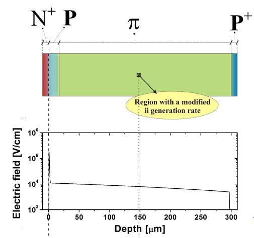
36 PiN Diode (No Gain) N + cathode P-type (π)substrate P + anode q Abrupt N + P junction with trapezoidal electric field profile (linearly decreasing in the P substrate) Electrons are accelerated towards the N + region until they reach the saturation velocity Since the electric field is much lower than E crit, electrons can not generate new carriers (no impact ionisation and no gain)
37 Pad Diode with internal Gain N + cathode P-type multiplication layer P-type (π)substrate P + anode q Gaussian N + P junction where the P-multiplication layer becomes completely depleted at a very low reverse voltage Electrons are accelerated towards the N + region until they reach the saturation velocity The electric field in the P layer is close to the E crit, value (impact ionisation and gain)


38 Conditions for Gain q Impact ionisation requires a minimum electric field of 1e5 V/cm in the P layer Full depletion of the P-type substrate is needed to avoid recombination The E crit value (~3e5 V/cm) can not be reached in the N + P junction (reverse breakdown) Impact ionisation region Electrons traveling at their saturation velocity (good for signal uniformity)
39 Gain Definition and Usage q The Gain can be defined in two equivalent ways and is identical whatever the incident particle is If no impact ionisation is contemplated (Equivalent PiN diode.) A known radiation source has to be used to calibrate the gain Collected charge is determined by integrating the current waveform The total number of generated electron-hole pairs in Silicon is determined by the type of radiation source q Once the Gain is calibrated, the detector can be used to identify the incident radiation by simply measuring the collected charge
40 Gain Simulation q Gain simulation considering generated and collected charge An initial charge distribution has to be introduced in the Sentaurus Heavy Ion model The evolution of the generated charge is calculated by transient simulations We have not been able to observe any transient current increase Impact ionisation is an statistic concept while transient simulation considers the evolution of each single electron q Gain simulation considering multiplied and non-multiplied current (alternative method) Ionisation coefficients are modified in a very small volume of the P-type substrate (3 orders of magnitude greater) to create a know number of electron-hole pairs (3000) Quasi static simulations are performed with and without the generated charge The PiN diode is simulated to determine current increase due to the generated charge (no impact ionisation is present) Then, the LGAD counterpart is simulated with and without charge (impact ionisation is present) Finally, the simulated Gain corresponds to the ratio between PiN and LGAD currents when charge is generated
41 Gain Simulation
42 Gain Simulation Local charge generation equivalent to the absorption of a 30 KeV X-ray The doping of the sample B P-multiplication layer is higher than the A sample (high Gain)

 induce great")
43 Design of the P-Multiplication Region q Doping profile of the P-multiplication layer is critical 1D Pad Centre Gain/V BD trade-off If implant dose increases: Gain increases V BD decreases Small modifications in the Boron implant dose (~ cm -2 ) induce great changes in Gain and V BD
44 Design of the Edge Termination q The optimisation of the edge termination is ruled by the electric field at the multiplication layer (not by the maximum voltage capability, as in the case of power devices) Correlated values P-Multiplication layer P-Substrate

45 Edge Termination: Why is needed? q The N + shallow contact and the P-multiplication layers have to be locally created with a lithography mask The electric field at the curvature of the N + /P junction is much higher than that of the plane junction (where Gain is needed) Avalanche at the N + /P curvature at a very low reverse voltage (premature breakdown) Shallow N + and P-multiplication layers self aligned High electric field peak at the curvature


46 Compatible Edge Termination Techniques Maximum efficiency of 80% Maximum efficiency of 60% Maximum efficiency of 90%
47 Edge Termination with Guard Ring q The N + shallow diffusion is used to implement a floating guard ring The lateral electric field distribution is smoothed leading to two peaks (main junction and floating guard ring) The electric field peak and the risk of avalanche breakdown at the curvature of the main junction is reduced. Optimisation of the guard ring location is needed
 The electric field rapidly increases at the plain junction (multiplication) At high reverse voltage the electric peak at the extended N + diffusion leads to")
48 Edge Termination with N + Extension q The N + shallow diffusion is used to extend the N + beyond the edge of the multiplication layer Phosphorous diffuses more in the very low doped substrate (higher curvature radius and voltage capability) The electric field rapidly increases at the plain junction (multiplication) At high reverse voltage the electric peak at the extended N + diffusion leads to avalanche breakdown Avalanche Multiplication
49 Edge Termination with Junction Termination Extension q Junction Termination Extension (JTE) with an additional deep N diffusion Additional photolithographic step with high energy Phosphorous implantation A field plate can also be implemented for additional electric field smoothing Field Plate N + cathode P-type multiplication layer JTE diffusion P-type substrate P + anode
 V BD plane < V BD JTE (Gain control) Multiplication and avalanche")
50 Edge Termination with Junction Termination Extension Deep N diffusion with high curvature radius (long anneal process) Reduced electric field peak at the JTE diffusion Highest electric field at the plane junction (gain control) V BD plane < V BD JTE (Gain control) Multiplication and avalanche control

51 Edge Termination with Junction Termination Extension Planar and uniform electric field distribution, high enough to activate charge multiplication Electric 400 V N + N P π

52 Design of the Device Periphery Full depletion below 100 V reverse bias Fast lateral depletion of the low doped substrate (A deep P + diffusion P stop- is needed in the die periphery to avoid the depletion region reaching the unprotected edge
 typically have a positive charge density")

53 What about the Inherent Positive Oxide Charges? x Field oxides grown in wet conditions (H 2 +O 2 ) typically have a positive charge density in the range of 5e10 cm -2 Surface inversion and modification of the depletion region, reaching the deep P-Stop peripheral diffusion Surface inversion + fast depletion + electric field peak at deep P-stop+ SURFACE LEAKAGE CURRENTS

 A shallow P-type diffusion (P-Spray) can be used to compensate")

54 How to Protect the Surface, Limiting the Current Leakage? q Oxide positive charges create a surface inversion layer (electron path towards the cathode electrode, masking the charge collection when used as a detector) A shallow P-type diffusion (P-Spray) can be used to compensate the surface inversion A deep P + diffusion can be placed close to the JTE to eliminate the electron surface current Blanket Boron implantation Same Boron implantation

55 How to Protect the Surface, Limiting the Current Leakage? q An additional N-type ring is implemented by using the deep JTE diffusion The N ring has to be placed close to the JTE to avoid a premature breakdown at the JTE The P-spray diffusion has to be efficient (to avoid short circuit through the inversion layer) The voltage capability is not degraded since the junction to be protected is now the right edge of the added ring (identical than the JTE) P N + N P - N N + Multiplier Junction Overlap Collector Ring P +
56 Simulation of the Irradiated Devices 600 V No Irradiated Irradiated. Φ eq = 1 x High Electric Field peak at the junction PiN: electric field strength at the junction increases after irradiation LGAD: electric field strength at the junction is almost equal after irradiation Irradiation Trap Model (Perugia Model) Acceptor; E= E c ev; η=0.9 σ e = 5 x σ h = 5 x Acceptor; E= E c ev; η=1.613 σ e = 2 x σ h = 2 x Acceptor; E= E c ev; η=100 σ e = 2 x σ h = 2.5 x Donor; E= E v ev; η=0.9 σ e = 2.5 x σ h = 2.5 x Impact Ionization Model (Univ. of Bolonia)
 Wafer 5 (1.")
57 Experimental Results Static Performance à Current levels below 1 µa thorough the whole voltage range à Junction breakdown above 1100 V W5_F11 Junction breakdown above 1100 V Current level (~ few hundreds of na) Wafer 5 ( cm -2 )
58 Experimental Results q Multiplication factor has been tested with tri-alpha ( 239 Pu/ 241 Am/ 244 Cm) source. Irradiation through the anode (back side, 1 µm Aluminum): Back Side Irradiation

59
Development of Radiation Hard Si Detectors
 Development of Radiation Hard Si Detectors Dr. Ajay K. Srivastava On behalf of Detector Laboratory of the Institute for Experimental Physics University of Hamburg, D-22761, Germany. Ajay K. Srivastava
Modelling of Diamond Devices with TCAD Tools
 RADFAC Day - 26 March 2015 Modelling of Diamond Devices with TCAD Tools A. Morozzi (1,2), D. Passeri (1,2), L. Servoli (2), K. Kanxheri (2), S. Lagomarsino (3), S. Sciortino (3) (1) Engineering Department
Semiconductor-Detectors
 Semiconductor-Detectors 1 Motivation ~ 195: Discovery that pn-- junctions can be used to detect particles. Semiconductor detectors used for energy measurements ( Germanium) Since ~ 3 years: Semiconductor
Ranjeet Dalal, Ashutosh Bhardwaj, Kirti Ranjan, Kavita Lalwani and Geetika Jain
 Simulation of Irradiated Si Detectors, Ashutosh Bhardwaj, Kirti Ranjan, Kavita Lalwani and Geetika Jain CDRST, Department of physics and Astrophysics, University of Delhi, India E-mail: rdalal@cern.ch
Energetic particles and their detection in situ (particle detectors) Part II. George Gloeckler
 Part II. George Gloeckler") Energetic particles and their detection in situ (particle detectors) Part II George Gloeckler University of Michigan, Ann Arbor, MI University of Maryland, College Park, MD Simple particle detectors Gas-filled
Energetic particles and their detection in situ (particle detectors) Part II George Gloeckler University of Michigan, Ann Arbor, MI University of Maryland, College Park, MD Simple particle detectors Gas-filled
Guard Ring Width Impact on Impact Parameter Performances and Structure Simulations
 LHCb-2003-034, VELO Note 13th May 2003 Guard Ring Width Impact on Impact Parameter Performances and Structure Simulations authors A Gouldwell, C Parkes, M Rahman, R Bates, M Wemyss, G Murphy The University
Accelerated ions. ion doping
 30 5. Simulation of Ion Doping of Semiconductors 5.1. Objectives - To give students hand-on experience of numerical simulation of ion doping used for fabrication of semiconductor planar devices. - To familiarize
Simulation results from double-sided and standard 3D detectors
 Simulation results from double-sided and standard 3D detectors David Pennicard, University of Glasgow Celeste Fleta, Chris Parkes, Richard Bates University of Glasgow G. Pellegrini, M. Lozano - CNM, Barcelona
This article has been accepted and published on J-STAGE in advance of copyediting. Content is final as presented.
 This article has been accepted and published on J-STAGE in advance of copyediting. Content is final as presented. References IEICE Electronics Express, Vol.* No.*,*-* Effects of Gamma-ray radiation on
Lecture 8. Detectors for Ionizing Particles
 Lecture 8 Detectors for Ionizing Particles Content Introduction Overview of detector systems Sources of radiation Radioactive decay Cosmic Radiation Accelerators Interaction of Radiation with Matter General
Lecture 18. New gas detectors Solid state trackers
 Lecture 18 New gas detectors Solid state trackers Time projection Chamber Full 3-D track reconstruction x-y from wires and segmented cathode of MWPC z from drift time de/dx information (extra) Drift over
R. Ludwig and G. Bogdanov RF Circuit Design: Theory and Applications 2 nd edition. Figures for Chapter 6
 R. Ludwig and G. Bogdanov RF Circuit Design: Theory and Applications 2 nd edition Figures for Chapter 6 Free electron Conduction band Hole W g W C Forbidden Band or Bandgap W V Electron energy Hole Valence
Lab1. Resolution and Throughput of Ion Beam Lithography.
 1 ENS/PHY463 Lab1. Resolution and Throughput of Ion Beam Lithography. (SRIM 2008/2013 computer simulation) Objective The objective of this laboratory work is to evaluate the exposure depth, resolution,
Radiation Effect Modeling
 Radiation Effect Modeling The design of electrical systems for military and space applications requires a consideration of the effects of transient and total dose radiation on system performance. Simulation
LECTURE 3 MOSFETS II. MOS SCALING What is Scaling?
 LECTURE 3 MOSFETS II Lecture 3 Goals* * Understand constant field and constant voltage scaling and their effects. Understand small geometry effects for MOS transistors and their implications modeling and
physics/ Sep 1997
 GLAS-PPE/97-6 28 August 1997 Department of Physics & Astronomy Experimental Particle Physics Group Kelvin Building, University of Glasgow, Glasgow, G12 8QQ, Scotland. Telephone: +44 - ()141 3398855 Fax:
Guard Ring Simulations for n-on-p Silicon Particle Detectors
 Physics Physics Research Publications Purdue University Year 2010 Guard Ring Simulations for n-on-p Silicon Particle Detectors O. Koybasi G. Bolla D. Bortoletto This paper is posted at Purdue e-pubs. http://docs.lib.purdue.edu/physics
Lecture 2. Introduction to semiconductors Structures and characteristics in semiconductors. Fabrication of semiconductor sensor
 Lecture 2 Introduction to semiconductors Structures and characteristics in semiconductors Semiconductor p-n junction Metal Oxide Silicon structure Semiconductor contact Fabrication of semiconductor sensor
Lab 3. Ion Implantation
 1 Lab 3. Ion Implantation (SRIM 2008/2013 computer simulation) 1. Objectives - To give students hand-on experience of numerical simulation of ion doping used for fabrication of semiconductor nanodevices.
Fundamentals of the Metal Oxide Semiconductor Field-Effect Transistor
 Triode Working FET Fundamentals of the Metal Oxide Semiconductor Field-Effect Transistor The characteristics of energy bands as a function of applied voltage. Surface inversion. The expression for the
Development of a Radiation Hard CMOS Monolithic Pixel Sensor
 Development of a Radiation Hard CMOS Monolithic Pixel Sensor M. Battaglia 1,2, D. Bisello 3, D. Contarato 2, P. Denes 2, D. Doering 2, P. Giubilato 2,3, T.S. Kim 2, Z. Lee 2, S. Mattiazzo 3, V. Radmilovic
Semiconductor Detectors
 Semiconductor Detectors Summary of Last Lecture Band structure in Solids: Conduction band Conduction band thermal conductivity: E g > 5 ev Valence band Insulator Charge carrier in conductor: e - Charge
Final Examination EE 130 December 16, 1997 Time allotted: 180 minutes
 Final Examination EE 130 December 16, 1997 Time allotted: 180 minutes Problem 1: Semiconductor Fundamentals [30 points] A uniformly doped silicon sample of length 100µm and cross-sectional area 100µm 2
Quiz #1 Practice Problem Set
 Name: Student Number: ELEC 3908 Physical Electronics Quiz #1 Practice Problem Set? Minutes January 22, 2016 - No aids except a non-programmable calculator - All questions must be answered - All questions
Semiconductor Physics fall 2012 problems
 Semiconductor Physics fall 2012 problems 1. An n-type sample of silicon has a uniform density N D = 10 16 atoms cm -3 of arsenic, and a p-type silicon sample has N A = 10 15 atoms cm -3 of boron. For each
Modeling of charge collection efficiency degradation in semiconductor devices induced by MeV ion beam irradiation
 Modeling of charge collection efficiency degradation in semiconductor devices induced by MeV ion beam irradiation Ettore Vittone Physics Department University of Torino - Italy 1 IAEA Coordinate Research
Stability of Semiconductor Memory Characteristics in a Radiation Environment
 SCIENTIFIC PUBLICATIONS OF THE STATE UNIVERSITY OF NOVI PAZAR SER. A: APPL. MATH. INFORM. AND MECH. vol. 7, 1 (2014), 33-39. Stability of Semiconductor Memory Characteristics in a Radiation Environment
Lecture 2. Introduction to semiconductors Structures and characteristics in semiconductors
 Lecture 2 Introduction to semiconductors Structures and characteristics in semiconductors Semiconductor p-n junction Metal Oxide Silicon structure Semiconductor contact Literature Glen F. Knoll, Radiation
Silicon Detectors in High Energy Physics
 Thomas Bergauer (HEPHY Vienna) IPM Teheran 22 May 2011 Sunday: Schedule Silicon Detectors in Semiconductor Basics (45 ) Detector concepts: Pixels and Strips (45 ) Coffee Break Strip Detector Performance
Chapter 7. The pn Junction
 Chapter 7 The pn Junction Chapter 7 PN Junction PN junction can be fabricated by implanting or diffusing donors into a P-type substrate such that a layer of semiconductor is converted into N type. Converting
STUDY OF SEMICONDUCTOR DEVICES EXPOSED TO SPATIAL RADIATION
 STUDY OF SEMICONDUCTOR DEVICES EXPOSED TO SPATIAL RADIATION G. DOMINGO YAGÜEZ 1, D. N. VILLARRAZA 1, M. A. CAPPELLETTI 1 y E. L. PELTZER y BLANCÁ 1,2 1 Grupo de Estudio de Materiales y Dispositivos Electrónicos
Lecture 2. Introduction to semiconductors Structures and characteristics in semiconductors
 Lecture 2 Introduction to semiconductors Structures and characteristics in semiconductors Semiconductor p-n junction Metal Oxide Silicon structure Semiconductor contact Literature Glen F. Knoll, Radiation
Aspects of radiation hardness for silicon microstrip detectors
 Aspects of radiation hardness for silicon microstrip detectors Richard Wheadon, INFN Pisa, Via Livornese 1291, S. Piero a Grado, Pisa, Italy Abstract The ways in which radiation damage affects the properties
Future trends in radiation hard electronics
 Future trends in radiation hard electronics F. Faccio CERN, Geneva, Switzerland Outline Radiation effects in CMOS technologies Deep submicron CMOS for radiation environments What is the future going to
Section 12: Intro to Devices
 Section 12: Intro to Devices Extensive reading materials on reserve, including Robert F. Pierret, Semiconductor Device Fundamentals EE143 Ali Javey Bond Model of Electrons and Holes Si Si Si Si Si Si Si
CONSTANT CURRENT STRESS OF ULTRATHIN GATE DIELECTRICS
 CONSTANT CURRENT STRESS OF ULTRATHIN GATE DIELECTRICS Y. Sun School of Electrical & Electronic Engineering Nayang Technological University Nanyang Avenue, Singapore 639798 e-mail: 14794258@ntu.edu.sg Keywords:
RD50 Recent Results - Development of radiation hard sensors for SLHC
 - Development of radiation hard sensors for SLHC Anna Macchiolo Max-Planck-Institut für Physik Föhringer Ring 6, Munich, Germany E-mail: Anna.Macchiolo@mppmu.mpg.de on behalf of the RD50 Collaboration
MOS CAPACITOR AND MOSFET
 EE336 Semiconductor Devices 1 MOS CAPACITOR AND MOSFET Dr. Mohammed M. Farag Ideal MOS Capacitor Semiconductor Devices Physics and Technology Chapter 5 EE336 Semiconductor Devices 2 MOS Capacitor Structure
X-ray induced radiation damage in segmented p + n silicon sensors
 in segmented p + n silicon sensors Jiaguo Zhang, Eckhart Fretwurst, Robert Klanner, Joern Schwandt Hamburg University, Germany E-mail: jiaguo.zhang@desy.de Deutsches Elektronen-Synchrotron (DESY), Germany
Solid State Electronics. Final Examination
 The University of Toledo EECS:4400/5400/7400 Solid State Electronic Section elssf08fs.fm - 1 Solid State Electronics Final Examination Problems Points 1. 1. 14 3. 14 Total 40 Was the exam fair? yes no
A new protocol to evaluate the charge collection efficiency degradation in semiconductor devices induced by MeV ions
 Session 12: Modification and Damage: Contribute lecture O-35 A new protocol to evaluate the charge collection efficiency degradation in semiconductor devices induced by MeV ions Ettore Vittone Physics
EE650R: Reliability Physics of Nanoelectronic Devices Lecture 18: A Broad Introduction to Dielectric Breakdown Date:
 EE650R: Reliability Physics of Nanoelectronic Devices Lecture 18: A Broad Introduction to Dielectric Breakdown Date: Nov 1, 2006 ClassNotes: Jing Li Review: Sayeef Salahuddin 18.1 Review As discussed before,
Radiation Effect Modeling
 Radiation Effect Modeling The design of electrical systems for military and space applications requires a consideration of the effects of transient and total dose radiation on system performance. Simulation
Study of radiation damage induced by 82 MeV protons on multipixel Geiger-mode avalanche photodiodes
 Study of radiation damage induced by 82 MeV protons on multipixel Geiger-mode avalanche photodiodes Y. Musienko*, S. Reucroft, J. Swain (Northeastern University, Boston) D. Renker, K. Dieters (PSI, Villigen)
23.0 Review Introduction
 EE650R: Reliability Physics of Nanoelectronic Devices Lecture 23: TDDB: Measurement of bulk trap density Date: Nov 13 2006 Classnotes: Dhanoop Varghese Review: Nauman Z Butt 23.0 Review In the last few
AIDA-2020 Advanced European Infrastructures for Detectors at Accelerators. Conference/Workshop Paper
 AIDA-2020-CONF-2016-007 AIDA-2020 Advanced European Infrastructures for Detectors at Accelerators Conference/Workshop Paper Measurements and TCAD Simulations of Bulk and Surface Radiation Damage Effects
Preliminary measurements of charge collection and DLTS analysis of p + /n junction SiC detectors and simulations of Schottky diodes
 Preliminary measurements of charge collection and DLTS analysis of p + /n junction SiC detectors and simulations of Schottky diodes F.Moscatelli, A.Scorzoni, A.Poggi, R.Nipoti DIEI and INFN Perugia and
SILICON PARTICLE DETECTOR
 SILICON PARTICLE DETECTOR Supervised Learning Project Eslikumar Adiandhra 12D260012 Department of Physics, IIT Bombay Guide: Prof. Raghava Varma Department of Physics, IIT Bombay November 8, 2015 Abstract
Challenges for Silicon Pixel Sensors at the XFEL. Table of Content
 Challenges for Silicon Pixel Sensors at the XFEL R.Klanner (Inst. Experimental Physics, Hamburg University) work by J.Becker, E.Fretwurst, I.Pintilie, T.Pöhlsen, J.Schwandt, J.Zhang Table of Content 1.Introduction:
Junction Diodes. Tim Sumner, Imperial College, Rm: 1009, x /18/2006
 Junction Diodes Most elementary solid state junction electronic devices. They conduct in one direction (almost correct). Useful when one converts from AC to DC (rectifier). But today diodes have a wide
Appendix 1: List of symbols
 Appendix 1: List of symbols Symbol Description MKS Units a Acceleration m/s 2 a 0 Bohr radius m A Area m 2 A* Richardson constant m/s A C Collector area m 2 A E Emitter area m 2 b Bimolecular recombination
ECEN 3320 Semiconductor Devices Final exam - Sunday December 17, 2000
 Your Name: ECEN 3320 Semiconductor Devices Final exam - Sunday December 17, 2000 1. Review questions a) Illustrate the generation of a photocurrent in a p-n diode by drawing an energy band diagram. Indicate
Chapter 2. Design and Fabrication of VLSI Devices
 Chapter 2 Design and Fabrication of VLSI Devices Jason Cong 1 Design and Fabrication of VLSI Devices Objectives: To study the materials used in fabrication of VLSI devices. To study the structure of devices
an introduction to Semiconductor Devices
 an introduction to Semiconductor Devices Donald A. Neamen Chapter 6 Fundamentals of the Metal-Oxide-Semiconductor Field-Effect Transistor Introduction: Chapter 6 1. MOSFET Structure 2. MOS Capacitor -
Gold Nanoparticles Floating Gate MISFET for Non-Volatile Memory Applications
 Gold Nanoparticles Floating Gate MISFET for Non-Volatile Memory Applications D. Tsoukalas, S. Kolliopoulou, P. Dimitrakis, P. Normand Institute of Microelectronics, NCSR Demokritos, Athens, Greece S. Paul,
EEE4106Z Radiation Interactions & Detection
 EEE4106Z Radiation Interactions & Detection 2. Radiation Detection Dr. Steve Peterson 5.14 RW James Department of Physics University of Cape Town steve.peterson@uct.ac.za May 06, 2015 EEE4106Z :: Radiation
Reduction of Self-heating effect in LDMOS devices
 Reduction of Self-heating effect in LDMOS devices T.K.Maiti * and C. K. Maiti ** Department of Electronics and Electrical Communication Engineering, Indian Institute of Technology, Kharagpur-721302, India
1 Name: Student number: DEPARTMENT OF PHYSICS AND PHYSICAL OCEANOGRAPHY MEMORIAL UNIVERSITY OF NEWFOUNDLAND. Fall :00-11:00
 1 Name: DEPARTMENT OF PHYSICS AND PHYSICAL OCEANOGRAPHY MEMORIAL UNIVERSITY OF NEWFOUNDLAND Final Exam Physics 3000 December 11, 2012 Fall 2012 9:00-11:00 INSTRUCTIONS: 1. Answer all seven (7) questions.
Stretching the Barriers An analysis of MOSFET Scaling. Presenters (in order) Zeinab Mousavi Stephanie Teich-McGoldrick Aseem Jain Jaspreet Wadhwa
 Zeinab Mousavi Stephanie Teich-McGoldrick Aseem Jain Jaspreet Wadhwa") Stretching the Barriers An analysis of MOSFET Scaling Presenters (in order) Zeinab Mousavi Stephanie Teich-McGoldrick Aseem Jain Jaspreet Wadhwa Why Small? Higher Current Lower Gate Capacitance Higher
Stretching the Barriers An analysis of MOSFET Scaling Presenters (in order) Zeinab Mousavi Stephanie Teich-McGoldrick Aseem Jain Jaspreet Wadhwa Why Small? Higher Current Lower Gate Capacitance Higher
Lecture 04 Review of MOSFET
 ECE 541/ME 541 Microelectronic Fabrication Techniques Lecture 04 Review of MOSFET Zheng Yang (ERF 3017, email: yangzhen@uic.edu) What is a Transistor? A Switch! An MOS Transistor V GS V T V GS S Ron D
Fabrication Technology, Part I
 EEL5225: Principles of MEMS Transducers (Fall 2004) Fabrication Technology, Part I Agenda: Microfabrication Overview Basic semiconductor devices Materials Key processes Oxidation Thin-film Deposition Reading:
Section 12: Intro to Devices
 Section 12: Intro to Devices Extensive reading materials on reserve, including Robert F. Pierret, Semiconductor Device Fundamentals Bond Model of Electrons and Holes Si Si Si Si Si Si Si Si Si Silicon
The outline. 1) Detector parameters: efficiency, geometrical acceptance, dead-time, resolution, linearity. 2) gaseous ionization chambers
 Detector parameters: efficiency, geometrical acceptance, dead-time, resolution, linearity. 2) gaseous ionization chambers") The outline 1) Detector parameters: efficiency, geometrical acceptance, dead-time, resolution, linearity 2) gaseous ionization chambers 3) proportional counters- ionization measurement 4) silicon detectors
The outline 1) Detector parameters: efficiency, geometrical acceptance, dead-time, resolution, linearity 2) gaseous ionization chambers 3) proportional counters- ionization measurement 4) silicon detectors
Device 3D. 3D Device Simulator. Nano Scale Devices. Fin FET
 Device 3D 3D Device Simulator Device 3D is a physics based 3D device simulator for any device type and includes material properties for the commonly used semiconductor materials in use today. The physical
Trench IGBT failure mechanisms evolution with temperature and gate resistance under various short-circuit conditions
 Author manuscript, published in "Microelectronics Reliability vol.47 (7) pp.173-1734" Trench IGBT failure mechanisms evolution with temperature and gate resistance under various short-circuit conditions
Components of a generic collider detector
 Lecture 24 Components of a generic collider detector electrons - ionization + bremsstrahlung photons - pair production in high Z material charged hadrons - ionization + shower of secondary interactions
Radiation Effects nm Si 3 N 4
 The Active DEPFET Pixel Sensor: Irradiation Effects due to Ionizing Radiation o Motivation / Radiation Effects o Devices and Facilities o Results o Summary and Conclusion MPI Semiconductor Laboratory Munich
Single Photon detectors
 Single Photon detectors Outline Motivation for single photon detection Semiconductor; general knowledge and important background Photon detectors: internal and external photoeffect Properties of semiconductor
Review Energy Bands Carrier Density & Mobility Carrier Transport Generation and Recombination
 Review Energy Bands Carrier Density & Mobility Carrier Transport Generation and Recombination The Metal-Semiconductor Junction: Review Energy band diagram of the metal and the semiconductor before (a)
The Devices: MOS Transistors
 The Devices: MOS Transistors References: Semiconductor Device Fundamentals, R. F. Pierret, Addison-Wesley Digital Integrated Circuits: A Design Perspective, J. Rabaey et.al. Prentice Hall NMOS Transistor
PN Junction
 P Junction 2017-05-04 Definition Power Electronics = semiconductor switches are used Analogue amplifier = high power loss 250 200 u x 150 100 u Udc i 50 0 0 50 100 150 200 250 300 350 400 i,u dc i,u u
Lecture 0: Introduction
 Lecture 0: Introduction Introduction q Integrated circuits: many transistors on one chip q Very Large Scale Integration (VLSI): bucketloads! q Complementary Metal Oxide Semiconductor Fast, cheap, low power
Basic Physics of Semiconductors
 Basic Physics of Semiconductors Semiconductor materials and their properties PN-junction diodes Reverse Breakdown EEM 205 Electronics I Dicle University, EEE Dr. Mehmet Siraç ÖZERDEM Semiconductor Physics
Semiconductor Physics Problems 2015
 Semiconductor Physics Problems 2015 Page and figure numbers refer to Semiconductor Devices Physics and Technology, 3rd edition, by SM Sze and M-K Lee 1. The purest semiconductor crystals it is possible
Semiconductor Physical Electronics
 Semiconductor Physical Electronics Sheng S. Li Department of Electrical Engineering University of Florida Gainesville, Florida Plenum Press New York and London Contents CHAPTER 1. Classification of Solids
Edgeless sensors for full-field X-ray imaging
 Edgeless sensors for full-field X-ray imaging 12 th iworid in Cambridge July 14 th, 2010 Marten Bosma 12 th iworid, Cambridge - July 14 th, 2010 Human X-ray imaging High spatial resolution Low-contrast
Joint ICTP-IAEA Workshop on Physics of Radiation Effect and its Simulation for Non-Metallic Condensed Matter.
 2359-3 Joint ICTP-IAEA Workshop on Physics of Radiation Effect and its Simulation for Non-Metallic Condensed Matter 13-24 August 2012 Electrically active defects in semiconductors induced by radiation
OPTI510R: Photonics. Khanh Kieu College of Optical Sciences, University of Arizona Meinel building R.626
 OPTI510R: Photonics Khanh Kieu College of Optical Sciences, University of Arizona kkieu@optics.arizona.edu Meinel building R.626 Announcements Homework #6 is assigned, due May 1 st Final exam May 8, 10:30-12:30pm
Ion Implantation. alternative to diffusion for the introduction of dopants essentially a physical process, rather than chemical advantages:
 Ion Implantation alternative to diffusion for the introduction of dopants essentially a physical process, rather than chemical advantages: mass separation allows wide varies of dopants dose control: diffusion
Heavy ion radiation damage simulations for CMOS image sensors
 Heavy ion radiation damage simulations for CMOS image sensors Henok Mebrahtu a, Wei Gao a, Paul J. Thomas b*, William E. Kieser c, Richard I. Hornsey a a Department of Computer Science, York University,
MOSFET: Introduction
 E&CE 437 Integrated VLSI Systems MOS Transistor 1 of 30 MOSFET: Introduction Metal oxide semiconductor field effect transistor (MOSFET) or MOS is widely used for implementing digital designs Its major
Introduction to Radiation Testing Radiation Environments
 http://www.maxwell.com/microelectronics/products/radtest/intro.html Introduction to Radiation Testing Quick links: Radiation Environments Total Dose Testing Single Event Effects Testing Neutron Testing
Tracking in High Energy Physics: Silicon Devices!
 Tracking in High Energy Physics: Silicon Devices! G. Leibenguth XIX Graduiertenkolleg Heidelberg 11-12. October 2007 Content Part 1: Basics on semi-conductor Part 2: Construction Part 3: Two Examples Part
Experimental Particle Physics
 Experimental Particle Physics Particle Interactions and Detectors Lecture 2 2nd May 2014 Fergus Wilson, RAL 1/31 How do we detect particles? Particle Types Charged (e - /K - /π - ) Photons (γ) Electromagnetic
Traps in MOCVD n-gan Studied by Deep Level Transient Spectroscopy and Minority Carrier Transient Spectroscopy
 Traps in MOCVD n-gan Studied by Deep Level Transient Spectroscopy and Minority Carrier Transient Spectroscopy Yutaka Tokuda Department of Electrical and Electronics Engineering, Aichi Institute of Technology,
Chapter 3 Basics Semiconductor Devices and Processing
 Chapter 3 Basics Semiconductor Devices and Processing Hong Xiao, Ph. D. www2.austin.cc.tx.us/hongxiao/book.htm Hong Xiao, Ph. D. www2.austin.cc.tx.us/hongxiao/book.htm 1 Objectives Identify at least two
ELEN0037 Microelectronic IC Design. Prof. Dr. Michael Kraft
 ELEN0037 Microelectronic IC Design Prof. Dr. Michael Kraft Lecture 2: Technological Aspects Technology Passive components Active components CMOS Process Basic Layout Scaling CMOS Technology Integrated
Session 6: Solid State Physics. Diode
 Session 6: Solid State Physics Diode 1 Outline A B C D E F G H I J 2 Definitions / Assumptions Homojunction: the junction is between two regions of the same material Heterojunction: the junction is between
Radiation Effects on Electronics. Dr. Brock J. LaMeres Associate Professor Electrical & Computer Engineering Montana State University
 Dr. Brock J. LaMeres Associate Professor Electrical & Computer Engineering Montana State University Research Statement Support the Computing Needs of Space Exploration & Science Computation Power Efficiency
Trench IGBT failure mechanisms evolution with temperature and gate resistance under various short-circuit conditions
 Trench IGBT failure mechanisms evolution with temperature and gate resistance under various short-circuit conditions Adel Benmansour, Stephane Azzopardi, Jean-Christophe Martin, Eric Woirgard To cite this
A Computational Model of NBTI and Hot Carrier Injection Time-Exponents for MOSFET Reliability
 Journal of Computational Electronics 3: 165 169, 2004 c 2005 Springer Science + Business Media, Inc. Manufactured in The Netherlands. A Computational Model of NBTI and Hot Carrier Injection Time-Exponents
Lecture 150 Basic IC Processes (10/10/01) Page ECE Analog Integrated Circuits and Systems P.E. Allen
 Page ECE Analog Integrated Circuits and Systems P.E. Allen") Lecture 150 Basic IC Processes (10/10/01) Page 1501 LECTURE 150 BASIC IC PROCESSES (READING: TextSec. 2.2) INTRODUCTION Objective The objective of this presentation is: 1.) Introduce the fabrication of
Lecture 150 Basic IC Processes (10/10/01) Page 1501 LECTURE 150 BASIC IC PROCESSES (READING: TextSec. 2.2) INTRODUCTION Objective The objective of this presentation is: 1.) Introduce the fabrication of
= (1) E inj. Minority carrier ionization. ln (at p ) Majority carrier ionization. ln (J e ) V, Eox. ~ 5eV
 E inj. Minority carrier ionization. ln (at p ) Majority carrier ionization. ln (J e ) V, Eox. ~ 5eV") EE650R: Reliability Physics of Nanoelectronic Devices Lecture 21: Application of Anode hole injection Model to Interpret Experiments Date: Nov 8 2006 ClassNotes: Vijay Rawat Reviewer: Haldun Kufluoglu
EE650R: Reliability Physics of Nanoelectronic Devices Lecture 21: Application of Anode hole injection Model to Interpret Experiments Date: Nov 8 2006 ClassNotes: Vijay Rawat Reviewer: Haldun Kufluoglu
Chem 481 Lecture Material 3/20/09
 Chem 481 Lecture Material 3/20/09 Radiation Detection and Measurement Semiconductor Detectors The electrons in a sample of silicon are each bound to specific silicon atoms (occupy the valence band). If
MOS Transistor I-V Characteristics and Parasitics
 ECEN454 Digital Integrated Circuit Design MOS Transistor I-V Characteristics and Parasitics ECEN 454 Facts about Transistors So far, we have treated transistors as ideal switches An ON transistor passes
Dark Current Limiting Mechanisms in CMOS Image Sensors
 Dark Current Limiting Mechanisms in CMOS Image Sensors Dan McGrath BAE Systems Information and Electronic Systems Integration Inc., Lexington, MA 02421, USA,
EE 5344 Introduction to MEMS CHAPTER 5 Radiation Sensors
 EE 5344 Introduction to MEMS CHAPTER 5 Radiation Sensors 5. Radiation Microsensors Radiation µ-sensors convert incident radiant signals into standard electrical out put signals. Radiant Signals Classification
Experimental Particle Physics
 Experimental Particle Physics Particle Interactions and Detectors Lecture 2 17th February 2010 Fergus Wilson, RAL 1/31 How do we detect particles? Particle Types Charged (e - /K - /π - ) Photons (γ) Electromagnetic
The electron accelerator of the ISOF-CNR Institute: its characteristics and use
 The electron accelerator of the ISOF-CNR Institute: its characteristics and use P. Fuochi, U. Corda, and M. Lavalle ISOF-CNR Institute, Via P. Gobetti 101, I-40129 Bologna, Italy LINAC Laboratory: ISOF-CNR,
Radiation Hardness Study on Double Sided 3D Sensors after Proton and Neutron Irradiation up to HL-LHC Fluencies
 Radiation Hardness Study on Double Sided 3D Sensors after Proton and Neutron Irradiation up to HL-LHC Fluencies D M S Sultan 1, G.-F. Dalla Betta 1, R. Mendicino 1, M. Boscardin 2 1 University of Trento