Types of Structures & Loads
|
|
|
- Allen Bridges
- 5 years ago
- Views:
Transcription
1 Structure Analysis I Chapter 4 1 Types of Structures & Loads 1Chapter
2 Chapter 4 Internal lloading Developed in Structural Members
3 Internal loading at a specified Point In General The loading for coplanar structure will consist of a normal force N, shear force V, and bending moment M. These loading actually represent the resultants of the stress distribution acting over the member s cross-sectional are

4 Sign Convention +ve Sign
5 Procedure for analysis Support Reaction Free-Body Diagram Equation of Equilibrium


6 Eample 1 Determine the internal shear and moment acting in the cantilever beam shown in figure at sections passing through points C & D
 5(2) 5(3) 20 = 0")
7 V C M c F y = 0 = 15kN M C = 0 V = 50kN. m C M = 0 c 5(1) 5(2) 5(3) 20 = 0

8 kn V V F C D y = = = kn m M M M kn V D D C C (3) 5(2) 5(1) 0 20 = = =
9 Eample 2 Determine the internal shear and moment acting in section 1 in the beam as shown in figure 18kN RA = RB = 9kN 6kN V F y = 0 V = 0 y = 3kN M at section = 0 M + 6(1) 9(2) = M D = 12kN. m 0


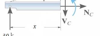
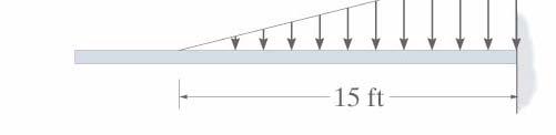
10 Eample 3 Determine the internal shear and moment acting in the cantilever beam shown in figure at sections passing through points C


 9(6) =")
11 V Fy = 0 VC = 0 = 6k M c = 0 M D = 48 k. ft M c + 3(2) 9(6) = 0
12 Shear and Moment function Procedure for Analysis: 1- Support reaction 2- Shear & Moment Function Specify separate coordinate and associated origins, etending into regions of the beam between concentrated forces and/or couple moments or where there is a discontinuity of distributed loading. Section the beam at distance and from the free body diagram determine V from, M at section
13 Eample 4 Determine the internal shear and moment Function


14 Eample 5 Determine the internal shear and moment Function

 ( 0.")

 30( 0 M M M S")
15 w = = w w V F = + = ) ( V V F y = ) 30( 0 M M M S + = = + + =
16 Eample 6 Determine the internal shear and moment Function


17 0 <12 < V V F y = = + = < < ( ) S M M M V = + + = = M + =
18 12 < < 20 2 V M = F y M 60 S = = 0 = V M = ( 6) 2 = 0
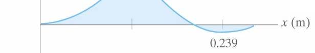
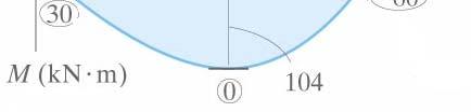
19 Eample 7 Determine the internal shear and moment Function
 10")

 3 2 3 2")

20 w = w w (20) V F y = + = ) ( V y = ( ) (20) M M M S + = = =
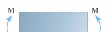
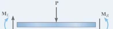
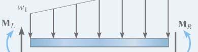
21 Shear and Moment diagram for a Beam
22 0 ) ( ) ( 0 V V w V F = + + = ( ) O 0 ) ( ) ( 0 ) ( 0 ) ( ) ( 0 M M w M V M w V V V w V F y = + + = = = + + = ε ( ) ( ) 2 O ) ( ) ( ) ( w V M + = ε = = d w V w d dv for ) ( ) ( 0 d V M V dm d ) ( = = d V M V d ) (
23 Eample 1 Draw shear force and Bending moment Diagram S.F.D B.M.D
24 Eample 2 Draw shear force and Bending moment Diagram S.F.D B.M.D
25 Eample 4 18 kn Draw shear force and Bending moment Diagram Ma. moment at = L/2 then wl M = 2 M ma = L 2 wl 8 2 w 2 L 2 2
26 Eample 3 Eample 3 Draw shear force and Bending moment Diagram
27 S.F.D B.M.D
28 Eample 5 Draw shear force and Bending moment Diagram 2 = 14 = 7 M S = M M = 49 14(3.5) + 14(7)


29 Eample 6a Draw shear force and Bending moment Diagram S.F.D B.M.D


30 Eample 6b Draw shear force and Bending moment Diagram S.F.D B.M.D


31 Eample 6c Draw shear force and Bending moment Diagram S.F.D BMD B.M.D


32 Eample 6d Eample 6d Draw shear force and Bending moment Diagram
33
34
35 Group Work Draw shear force and Bending moment Diagram
36


37 Eample 1 Draw shear force and Bending moment Diagram

38 V(kN)
39 Eample 2 Draw shear force and Bending moment Diagram

40 +


41 Eample 2 Draw shear force and Bending moment Diagram
42 Eample 3 Draw shear force and Bending moment Diagram
43

44 Eample 4 Draw shear force and Bending moment Diagram
45 + + +

46 Problem 1 Draw shear force and Bending moment Diagram
47
48 Problem 2 Draw shear force and Bending moment Diagram


(5)")
49 2 3 at 5 = M M V = 2 = 0 ( R = A = 3.46 m ) = 2 3 (3.46)(5)
50 Eample 1 Draw shear force and Bending moment Diagram Hinge
51 Reaction Calculation ( ) k A A M y left B (5) 10 0 = + = Reaction Calculation k C C M k A y y E y (32) 20(27) 5(16) 18(6) (12) 0 4 = = = = k E E E F y F 0 0 y = = = = E y 6k =
52


53 Frames (Eample 1) Draw Bending moment Diagram


54 Support reaction & Free Body diagram
55

56 S.F.D B.M.D
57 + S.F.D - - BMD B.M.D
58 Frames (Eample 2) Draw shear force and Bending moment Diagram
59


60 + N.F.D + _ S.F.D NFD N.F.D SFD S.F.D BMD B.M.D B.M.D N.F.D -
61 Frames (Eample 3) Draw shear force and Bending moment Diagram
62
63 N.F.D S.F.D B.M.D - - -

64 _ N.F.D S.F.D + B.M.D 251.6

65 N.F.D S.F.D B.M.D 168


66 S.F.D _ _ _ _ B.M.D
67 Frames (Eample 4) Draw shear force and Bending moment Diagram

68
69


70 S.F.D B.M.D + +


71 _ S.F.D + B.M.D
 Draw shear")

72 Frames (Eample 5) Draw shear force and Bending moment Diagram

73
74 Frames (Eample 6) Draw shear force and Bending moment Diagram
75
76 N.F.D S.F.D B.M.D _
77 _ N.F.D + _ + S.F.D _ + _ B.M.D

78 B.M.D S.F.D N.F.D _ + _
79 Frames (Eample 7) Draw Normal force, shear force and Bending moment Diagram
80 10kN/m 60kN o
81 NFD N.F.D SFD S.F.D BMD B.M.D S.F.D B.M.D


82 N.F.D S.F.D B.M.D
83 BMD B.M.D

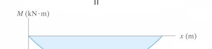
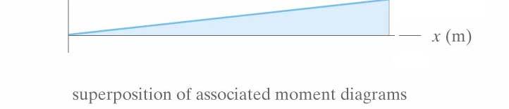
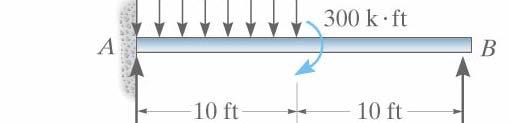
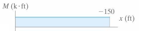
84 Moment diagram constructed by the Eample 1 method of superposition
85

86


87 Eample 2.a
88
89 Eample 2.b
90


91 Problem 1 Draw Normal force, shear force and Bending moment Diagram

92 Problem 2 Draw Normal force, shear force and Bending moment Diagram
Tutorial #1 - CivE. 205 Name: I.D:
 Tutorial # - CivE. 0 Name: I.D: Eercise : For the Beam below: - Calculate the reactions at the supports and check the equilibrium of point a - Define the points at which there is change in load or beam
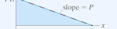
dv dx Slope of the shear diagram = - Value of applied loading dm dx Slope of the moment curve = Shear Force
 Beams SFD and BMD Shear and Moment Relationships w dv dx Slope of the shear diagram = - Value of applied loading V dm dx Slope of the moment curve = Shear Force Both equations not applicable at the point
- Beams are structural member supporting lateral loadings, i.e., these applied perpendicular to the axes.
 4. Shear and Moment functions - Beams are structural member supporting lateral loadings, i.e., these applied perpendicular to the aes. - The design of such members requires a detailed knowledge of the
Internal Internal Forces Forces
 Internal Forces ENGR 221 March 19, 2003 Lecture Goals Internal Force in Structures Shear Forces Bending Moment Shear and Bending moment Diagrams Internal Forces and Bending The bending moment, M. Moment
Bending Stress. Sign convention. Centroid of an area
 Bending Stress Sign convention The positive shear force and bending moments are as shown in the figure. Centroid of an area Figure 40: Sign convention followed. If the area can be divided into n parts
Beams. Beams are structural members that offer resistance to bending due to applied load
 Beams Beams are structural members that offer resistance to bending due to applied load 1 Beams Long prismatic members Non-prismatic sections also possible Each cross-section dimension Length of member
Chapter 4.1: Shear and Moment Diagram
 Chapter 4.1: Shear and Moment Diagram Chapter 5: Stresses in Beams Chapter 6: Classical Methods Beam Types Generally, beams are classified according to how the beam is supported and according to crosssection
Unit II Shear and Bending in Beams
 Unit II Shear and Bending in Beams Syllabus: Beams and Bending- Types of loads, supports - Shear Force and Bending Moment Diagrams for statically determinate beam with concentrated load, UDL, uniformly
8.3 Shear and Bending-Moment Diagrams Constructed by Areas
 8.3 Shear and ending-moment Diagrams Constructed by reas 8.3 Shear and ending-moment Diagrams Constructed by reas Procedures and Strategies, page 1 of 3 Procedures and Strategies for Solving Problems Involving
Chapter 2. Shear Force and Bending Moment. After successfully completing this chapter the students should be able to:
 Chapter Shear Force and Bending Moment This chapter begins with a discussion of beam types. It is also important for students to know and understand the reaction from the types of supports holding the
Beams are bars of material that support. Beams are common structural members. Beams can support both concentrated and distributed loads
 Outline: Review External Effects on Beams Beams Internal Effects Sign Convention Shear Force and Bending Moment Diagrams (text method) Relationships between Loading, Shear Force and Bending Moments (faster
TYPES OF STRUCUTRES. HD in Civil Engineering Page 1-1
 E2027 Structural nalysis I TYPES OF STRUUTRES H in ivil Engineering Page 1-1 E2027 Structural nalysis I SUPPORTS Pin or Hinge Support pin or hinge support is represented by the symbol H or H V V Prevented:
Shear Force and Bending Moment Diagrams for a Beam Steven Vukazich San Jose State University
 Shear Force and Bending oment Diagrams for a Beam Steven ukazich San Jose State University General procedure for the construction of internal force diagrams 1. Find all of the eternal forces and draw the
Shear Force V: Positive shear tends to rotate the segment clockwise.
 INTERNL FORCES IN EM efore a structural element can be designed, it is necessary to determine the internal forces that act within the element. The internal forces for a beam section will consist of a shear
QUESTION BANK. SEMESTER: V SUBJECT CODE / Name: CE 6501 / STRUCTURAL ANALYSIS-I
 QUESTION BANK DEPARTMENT: CIVIL SEMESTER: V SUBJECT CODE / Name: CE 6501 / STRUCTURAL ANALYSIS-I Unit 5 MOMENT DISTRIBUTION METHOD PART A (2 marks) 1. Differentiate between distribution factors and carry
8-5 Conjugate-Beam method. 8-5 Conjugate-Beam method. 8-5 Conjugate-Beam method. 8-5 Conjugate-Beam method
 The basis for the method comes from the similarity of eqn.1 &. to eqn 8. & 8. To show this similarity, we can write these eqn as shown dv dx w d θ M dx d M w dx d v M dx Here the shear V compares with
BEAM A horizontal or inclined structural member that is designed to resist forces acting to its axis is called a beam
 BEM horizontal or inclined structural member that is designed to resist forces acting to its axis is called a beam INTERNL FORCES IN BEM Whether or not a beam will break, depend on the internal resistances
ENG202 Statics Lecture 16, Section 7.1
 ENG202 Statics Lecture 16, Section 7.1 Internal Forces Developed in Structural Members - Design of any structural member requires an investigation of the loading acting within the member in order to be
Stress Analysis Lecture 4 ME 276 Spring Dr./ Ahmed Mohamed Nagib Elmekawy
 Stress Analysis Lecture 4 ME 76 Spring 017-018 Dr./ Ahmed Mohamed Nagib Elmekawy Shear and Moment Diagrams Beam Sign Convention The positive directions are as follows: The internal shear force causes a
Chapter 7: Internal Forces
 Chapter 7: Internal Forces Chapter Objectives To show how to use the method of sections for determining the internal loadings in a member. To generalize this procedure by formulating equations that can
2. Determine the deflection at C of the beam given in fig below. Use principal of virtual work. W L/2 B A L C
 CE-1259, Strength of Materials UNIT I STRESS, STRAIN DEFORMATION OF SOLIDS Part -A 1. Define strain energy density. 2. State Maxwell s reciprocal theorem. 3. Define proof resilience. 4. State Castigliano
ENR202 Mechanics of Materials Lecture 4A Notes and Slides
 Slide 1 Copyright Notice Do not remove this notice. COMMMONWEALTH OF AUSTRALIA Copyright Regulations 1969 WARNING This material has been produced and communicated to you by or on behalf of the University
Deflection of Beams. Equation of the Elastic Curve. Boundary Conditions
 Deflection of Beams Equation of the Elastic Curve The governing second order differential equation for the elastic curve of a beam deflection is EI d d = where EI is the fleural rigidit, is the bending
SAB2223 Mechanics of Materials and Structures
 S2223 Mechanics of Materials and Structures TOPIC 2 SHER FORCE ND ENDING MOMENT Lecturer: Dr. Shek Poi Ngian TOPIC 2 SHER FORCE ND ENDING MOMENT Shear Force and ending Moment Introduction Types of beams
REVIEW FOR EXAM II. Dr. Ibrahim A. Assakkaf SPRING 2002
 REVIEW FOR EXM II. J. Clark School of Engineering Department of Civil and Environmental Engineering b Dr. Ibrahim. ssakkaf SPRING 00 ENES 0 Mechanics of Materials Department of Civil and Environmental
PURE BENDING. If a simply supported beam carries two point loads of 10 kn as shown in the following figure, pure bending occurs at segment BC.
 BENDING STRESS The effect of a bending moment applied to a cross-section of a beam is to induce a state of stress across that section. These stresses are known as bending stresses and they act normally
Module 2. Analysis of Statically Indeterminate Structures by the Matrix Force Method
 Module 2 Analysis of Statically Indeterminate Structures by the Matrix Force Method Lesson 8 The Force Method of Analysis: Beams Instructional Objectives After reading this chapter the student will be
6. Bending CHAPTER OBJECTIVES
 CHAPTER OBJECTIVES Determine stress in members caused by bending Discuss how to establish shear and moment diagrams for a beam or shaft Determine largest shear and moment in a member, and specify where
Problem d d d B C E D. 0.8d. Additional lecturebook examples 29 ME 323
 Problem 9.1 Two beam segments, AC and CD, are connected together at C by a frictionless pin. Segment CD is cantilevered from a rigid support at D, and segment AC has a roller support at A. a) Determine
PROBLEM 7.37 SOLUTION
 PROLEM 7.37 For the beam and loading shown, (a) draw the shear and bending-moment diagrams, (b) determine the maimum absolute values of the shear and bending moment. Free bod: Entire beam Σ M = 0: E(6
Mechanics of Structure
 S.Y. Diploma : Sem. III [CE/CS/CR/CV] Mechanics of Structure Time: Hrs.] Prelim Question Paper Solution [Marks : 70 Q.1(a) Attempt any SIX of the following. [1] Q.1(a) Define moment of Inertia. State MI
ES120 Spring 2018 Section 7 Notes
 ES120 Spring 2018 Section 7 Notes Matheus Fernandes March 29, 2018 Problem 1: For the beam and loading shown, (a) determine the equations of the shear and bending-moment curves, (b) draw the shear and
UNIT-V MOMENT DISTRIBUTION METHOD
 UNIT-V MOMENT DISTRIBUTION METHOD Distribution and carryover of moments Stiffness and carry over factors Analysis of continuous beams Plane rigid frames with and without sway Neylor s simplification. Hardy
Procedure for drawing shear force and bending moment diagram:
 Procedure for drawing shear force and bending moment diagram: Preamble: The advantage of plotting a variation of shear force F and bending moment M in a beam as a function of x' measured from one end of
MECHANICS OF MATERIALS. Analysis of Beams for Bending
 MECHANICS OF MATERIALS Analysis of Beams for Bending By NUR FARHAYU ARIFFIN Faculty of Civil Engineering & Earth Resources Chapter Description Expected Outcomes Define the elastic deformation of an axially
Laith Batarseh. internal forces
 Next Previous 1/8/2016 Chapter seven Laith Batarseh Home End Definitions When a member is subjected to external load, an and/or moment are generated inside this member. The value of the generated internal
ENGINEERING SCIENCE H1 OUTCOME 1 - TUTORIAL 2 SHEAR FORCE IN BEAMS EDEXCEL HNC/D ENGINEERING SCIENCE LEVEL 4 H1 FORMERLY UNIT 21718P
 ENGINEERING SCIENCE H1 OUTCOME 1 - TUTORIAL 2 SHEAR FORCE IN BEAMS EDEXCEL HNC/D ENGINEERING SCIENCE LEVEL 4 H1 FORMERLY UNIT 21718P This material is duplicated in the Mechanical Principles module H2 and
UNIT II 1. Sketch qualitatively the influence line for shear at D for the beam [M/J-15]
![UNIT II 1. Sketch qualitatively the influence line for shear at D for the beam [M/J-15]](/thumbs/95/124878500.jpg "UNIT II 1. Sketch qualitatively the influence line for shear at D for the beam [M/J-15]") UNIT II 1. Sketch qualitatively the influence line for shear at D for the beam [M/J-15] 2. Draw the influence line for shear to the left of B for the overhanging beam shown in Fig. Q. No. 4 [M/J-15] 3.
UNIT II 1. Sketch qualitatively the influence line for shear at D for the beam [M/J-15] 2. Draw the influence line for shear to the left of B for the overhanging beam shown in Fig. Q. No. 4 [M/J-15] 3.
CIV E 205 Mechanics of Solids II. Course Notes
 Department of Civil Engineering CIV E 205 Mechanics of Solids II Instructor: Tarek Hegazi Email: tarek@uwaterloo.ca Course Notes Mechanics of Materials Objectives: - Solve Problems in a structured systematic
INFLUENCE LINE. Structural Analysis. Reference: Third Edition (2005) By Aslam Kassimali
 By Aslam Kassimali") INFLUENCE LINE Reference: Structural Analsis Third Edition (2005) B Aslam Kassimali DEFINITION An influence line is a graph of a response function of a structure as a function of the position of a downward
INFLUENCE LINE Reference: Structural Analsis Third Edition (2005) B Aslam Kassimali DEFINITION An influence line is a graph of a response function of a structure as a function of the position of a downward
CHAPTER 7 DEFLECTIONS OF BEAMS
 CHPTER 7 DEFLECTIONS OF EMS OJECTIVES Determine the deflection and slope at specific points on beams and shafts, using various analytical methods including: o o o The integration method The use of discontinuity
For more Stuffs Visit Owner: N.Rajeev. R07
 Code.No: 43034 R07 SET-1 JAWAHARLAL NEHRU TECHNOLOGICAL UNIVERSITY HYDERABAD II.B.TECH - I SEMESTER REGULAR EXAMINATIONS NOVEMBER, 2009 FOUNDATION OF SOLID MECHANICS (AERONAUTICAL ENGINEERING) Time: 3hours
UNIT IV FLEXIBILTY AND STIFFNESS METHOD
 SIDDHARTH GROUP OF INSTITUTIONS :: PUTTUR Siddharth Nagar, Narayanavanam Road 517583 QUESTION BANK (DESCRIPTIVE) Subject with Code : SA-II (13A01505) Year & Sem: III-B.Tech & I-Sem Course & Branch: B.Tech
STRUCTURAL ANALYSIS BFC Statically Indeterminate Beam & Frame
 STRUCTURA ANAYSIS BFC 21403 Statically Indeterminate Beam & Frame Introduction Analysis for indeterminate structure of beam and frame: 1. Slope-deflection method 2. Moment distribution method Displacement
Supplement: Statically Indeterminate Frames
 : Statically Indeterminate Frames Approximate Analysis - In this supplement, we consider another approximate method of solving statically indeterminate frames subjected to lateral loads known as the. Like
Determinate portal frame
 eterminate portal frame onsider the frame shown in the figure below with the aim of calculating the bending moment diagram (M), shear force diagram (SF), and axial force diagram (F). P H y R x x R y L
CIV100 Mechanics. Module 5: Internal Forces and Design. by: Jinyue Zhang. By the end of this Module you should be able to:
 CIV100 Mechanics Module 5: Internal Forces and Design by: Jinyue Zhang Module Objective By the end of this Module you should be able to: Find internal forces of any structural members Understand how Shear
CHAPTER 8 BENDING MOMENT AND SHEAR FORCE DIAGRAMS
 CHPTE 8 BENDING MOMENT ND SHE FOCE DIGMS EXECISE 5, Page. Determine expressions for the bending moment and shearing force distributions for the following simply supported beam; hence, or otherwise, plot
EMA 3702 Mechanics & Materials Science (Mechanics of Materials) Chapter 5 Beams for Bending
 Chapter 5 Beams for Bending") MA 3702 Mechanics & Materials Science (Mechanics of Materials) Chapter 5 Beams for Bending Introduction esign of beams for mechanical or civil/structural applications Transverse loading in most cases for
MA 3702 Mechanics & Materials Science (Mechanics of Materials) Chapter 5 Beams for Bending Introduction esign of beams for mechanical or civil/structural applications Transverse loading in most cases for
Structural Steel Design Project
 Job No: Sheet 1 of 6 Rev Worked Example - 1 Made by Date 4-1-000 Checked by PU Date 30-4-000 Analyse the building frame shown in Fig. A using portal method. 15 kn C F I L 4 m 0 kn B E H K 6 m A D G J 4
STRENGTH OF MATERIALS-I. Unit-1. Simple stresses and strains
 STRENGTH OF MATERIALS-I Unit-1 Simple stresses and strains 1. What is the Principle of surveying 2. Define Magnetic, True & Arbitrary Meridians. 3. Mention different types of chains 4. Differentiate between
PROBLEM 5.1. wl x. M ( Lx x )
") w PROE 5.1 For the beam and loading shown, (a) draw the shear and bending-moment diagrams, (b) determine the equations of the shear and bending-moment curves. SOUTION Reactions: 0: 0 0: 0 Free bod diagram
w PROE 5.1 For the beam and loading shown, (a) draw the shear and bending-moment diagrams, (b) determine the equations of the shear and bending-moment curves. SOUTION Reactions: 0: 0 0: 0 Free bod diagram
MECE 3321: Mechanics of Solids Chapter 6
 MECE 3321: Mechanics of Solids Chapter 6 Samantha Ramirez Beams Beams are long straight members that carry loads perpendicular to their longitudinal axis Beams are classified by the way they are supported
SLOPE-DEFLECTION METHOD
 SLOPE-DEFLECTION ETHOD The slope-deflection method uses displacements as unknowns and is referred to as a displacement method. In the slope-deflection method, the moments at the ends of the members are
CIVIL DEPARTMENT MECHANICS OF STRUCTURES- ASSIGNMENT NO 1. Brach: CE YEAR:
 MECHANICS OF STRUCTURES- ASSIGNMENT NO 1 SEMESTER: V 1) Find the least moment of Inertia about the centroidal axes X-X and Y-Y of an unequal angle section 125 mm 75 mm 10 mm as shown in figure 2) Determine
 techie-touch.blogspot.com DEPARTMENT OF CIVIL ENGINEERING ANNA UNIVERSITY QUESTION BANK CE 2302 STRUCTURAL ANALYSIS-I TWO MARK QUESTIONS UNIT I DEFLECTION OF DETERMINATE STRUCTURES 1. Write any two important
BEAM DEFLECTION THE ELASTIC CURVE
 BEAM DEFLECTION Samantha Ramirez THE ELASTIC CURVE The deflection diagram of the longitudinal axis that passes through the centroid of each cross-sectional area of a beam. Supports that apply a moment
Chapter Objectives. Copyright 2011 Pearson Education South Asia Pte Ltd
 Chapter Objectives To generalize the procedure by formulating equations that can be plotted so that they describe the internal shear and moment throughout a member. To use the relations between distributed
Deflections. Deflections. Deflections. Deflections. Deflections. Deflections. dx dm V. dx EI. dx EI dx M. dv w
 CIVL 311 - Conjugate eam 1/5 Conjugate beam method The development of the conjugate beam method has been atributed to several strucutral engineers. any credit Heinrich üller-reslau (1851-195) with the
Chapter 11. Displacement Method of Analysis Slope Deflection Method
 Chapter 11 Displacement ethod of Analysis Slope Deflection ethod Displacement ethod of Analysis Two main methods of analyzing indeterminate structure Force method The method of consistent deformations
Shear Force and Bending Moment Diagrams
 Shear Force and Bending Moment Diagrams V [ N ] x[m] M [ Nm] x[m] Competencies 1. Draw shear force and bending moment diagrams for point loads and distributed loads 2. Recognize the position of maximum
SSC-JE MAINS ONLINE TEST SERIES / CIVIL ENGINEERING SOM + TOS
 SSC-JE MAINS ONLINE TEST SERIES / CIVIL ENGINEERING SOM + TOS Time Allowed:2 Hours Maximum Marks: 300 Attention: 1. Paper consists of Part A (Civil & Structural) Part B (Electrical) and Part C (Mechanical)
UNIT-II MOVING LOADS AND INFLUENCE LINES
 UNIT-II MOVING LOADS AND INFLUENCE LINES Influence lines for reactions in statically determinate structures influence lines for member forces in pin-jointed frames Influence lines for shear force and bending
SIGN CONVENTION OF STRESS RESULTANTS
 SIGN CONVENTION OF STRESS RESULTANTS A quick guide to understanding the sign conventions used in the ush Me ull Me models National HE STEM rogramme INTRODUCTION Representing stress resultants graphically
University of Pretoria Department of Mechanical & Aeronautical Engineering MOW 227, 2 nd Semester 2014
 Universit of Pretoria Department of Mechanical & Aeronautical Engineering MOW 7, nd Semester 04 Semester Test Date: August, 04 Total: 00 Internal eaminer: Duration: hours Mr. Riaan Meeser Instructions:
Lecture 7: The Beam Element Equations.
 4.1 Beam Stiffness. A Beam: A long slender structural component generally subjected to transverse loading that produces significant bending effects as opposed to twisting or axial effects. MECH 40: Finite
Beam Design and Deflections
 Beam Design and Deflections tation: a = name for width dimension A = name for area Areq d-adj = area required at allowable stress when shear is adjusted to include self weight Aweb = area of the web of
 UNIT III DEFLECTION OF BEAMS 1. What are the methods for finding out the slope and deflection at a section? The important methods used for finding out the slope and deflection at a section in a loaded
STRUCTURAL ANALYSIS CHAPTER 2. Introduction
 CHAPTER 2 STRUCTURAL ANALYSIS Introduction The primary purpose of structural analysis is to establish the distribution of internal forces and moments over the whole part of a structure and to identify
= 50 ksi. The maximum beam deflection Δ max is not = R B. = 30 kips. Notes for Strength of Materials, ET 200
 Notes for Strength of Materials, ET 00 Steel Six Easy Steps Steel beam design is about selecting the lightest steel beam that will support the load without exceeding the bending strength or shear strength
Stress Engineering Interview Questions Part 1
 Stress Engineering Interview Questions Part 1 Author: Surya Batchu Senior Stress Engineer Founder, STRESS EBOOK LLC. http://www.stressebook.com 1 P a g e Stress Engineering Interview Questions Part 1:
6/6/2008. Qualitative Influence Lines for Statically Indeterminate Structures: Muller-Breslau s Principle
 Qualitative Influence Lines for Statically Indeterminate Structures: Muller-Breslau s Principle The influence line for a force (or moment) response function is given by the deflected shape of the released
Hong Kong Institute of Vocational Education (Tsing Yi) Higher Diploma in Civil Engineering Structural Mechanics. Chapter 1 PRINCIPLES OF STATICS
 Higher Diploma in Civil Engineering Structural Mechanics. Chapter 1 PRINCIPLES OF STATICS") PRINCIPLES OF STTICS Statics is the study of how forces act and react on rigid bodies which are at rest or not in motion. This study is the basis for the engineering principles, which guide the design
PRINCIPLES OF STTICS Statics is the study of how forces act and react on rigid bodies which are at rest or not in motion. This study is the basis for the engineering principles, which guide the design
FRAME ANALYSIS. Dr. Izni Syahrizal bin Ibrahim. Faculty of Civil Engineering Universiti Teknologi Malaysia
 FRAME ANALYSIS Dr. Izni Syahrizal bin Ibrahim Faculty of Civil Engineering Universiti Teknologi Malaysia Email: iznisyahrizal@utm.my Introduction 3D Frame: Beam, Column & Slab 2D Frame Analysis Building
Solution ME 323 EXAM #2 FALL SEMESTER :00 PM 9:30 PM Nov. 2, 2010
 Solution ME 33 EXAM # FALL SEMESTER 1 8: PM 9:3 PM Nov., 1 Instructions 1. Begin each problem in the space provided on the eamination sheets. If additional space is required, use the paper provided. Work
3 Hours/100 Marks Seat No.
 *17304* 17304 14115 3 Hours/100 Marks Seat No. Instructions : (1) All questions are compulsory. (2) Illustrate your answers with neat sketches wherever necessary. (3) Figures to the right indicate full
CIV E 205 Mechanics of Solids II. Course Notes
 University of Waterloo Department of Civil Engineering CIV E 205 Mechanics of Solids II Instructor: Tarek Hegazi Room: CPH 2373 G, Ext. 2174 Email: tarek@uwaterloo.ca Course Web: www.civil.uwaterloo.ca/tarek/hegazy205.html
Chapter 7 FORCES IN BEAMS AND CABLES
 hapter 7 FORES IN BEAMS AN ABLES onsider a straight two-force member AB subjected at A and B to equal and opposite forces F and -F directed along AB. utting the member AB at and drawing the free-body B
ENGINEERING MECHANICS SOLUTIONS UNIT-I
 LONG QUESTIONS ENGINEERING MECHANICS SOLUTIONS UNIT-I 1. A roller shown in Figure 1 is mass 150 Kg. What force P is necessary to start the roller over the block A? =90+25 =115 = 90+25.377 = 115.377 = 360-(115+115.377)
CIV E 205 Mechanics of Solids II. Course Notes
 University of Waterloo Department of Civil Engineering CIV E 205 Mechanics of Solids II Instructor: Tarek Hegazi Room: CPH 2373 G, Ext. 2174 Email: tarek@uwaterloo.ca Course Web: www.civil.uwaterloo.ca/tarek/205-2005.html
 SRI VIDYA COLLEGE OF ENGINEERING AND TECHNOLOGY, VIRUDHUNAGAR CE 6602 STRUCTURAL ANALYSIS - II DEPARTMENT OF CIVIL ENGINEERING CE 6501 STRUCTURAL ANALYSIS - I 2 MARK QUESTION BANK UNIT II - INFLUENCE LINES
UNIT-I STRESS, STRAIN. 1. A Member A B C D is subjected to loading as shown in fig determine the total elongation. Take E= 2 x10 5 N/mm 2
 UNIT-I STRESS, STRAIN 1. A Member A B C D is subjected to loading as shown in fig determine the total elongation. Take E= 2 x10 5 N/mm 2 Young s modulus E= 2 x10 5 N/mm 2 Area1=900mm 2 Area2=400mm 2 Area3=625mm
P.E. Civil Exam Review:
 P.E. Civil Exam Review: Structural Analysis J.P. Mohsen Email: jpm@louisville.edu Structures Determinate Indeterminate STATICALLY DETERMINATE STATICALLY INDETERMINATE Stability and Determinacy of Trusses
2 marks Questions and Answers
 1. Define the term strain energy. A: Strain Energy of the elastic body is defined as the internal work done by the external load in deforming or straining the body. 2. Define the terms: Resilience and
Shear Forces And Bending Moments
 Shear Forces And Bending Moments 1 Introduction 2001 Brooks/Cole, a division of Thomson Learning, Inc. Thomson Learning is a trademark used herein under license. Fig. 4-1 Examples of beams subjected to
[8] Bending and Shear Loading of Beams
![[8] Bending and Shear Loading of Beams](/thumbs/92/110949676.jpg "[8] Bending and Shear Loading of Beams") [8] Bending and Shear Loading of Beams Page 1 of 28 [8] Bending and Shear Loading of Beams [8.1] Bending of Beams (will not be covered in class) [8.2] Bending Strain and Stress [8.3] Shear in Straight
[8] Bending and Shear Loading of Beams Page 1 of 28 [8] Bending and Shear Loading of Beams [8.1] Bending of Beams (will not be covered in class) [8.2] Bending Strain and Stress [8.3] Shear in Straight
Module 3. Analysis of Statically Indeterminate Structures by the Displacement Method
 odule 3 Analysis of Statically Indeterminate Structures by the Displacement ethod Lesson 16 The Slope-Deflection ethod: rames Without Sidesway Instructional Objectives After reading this chapter the student
Software Verification
 EXAMPLE 1-026 FRAME MOMENT AND SHEAR HINGES EXAMPLE DESCRIPTION This example uses a horizontal cantilever beam to test the moment and shear hinges in a static nonlinear analysis. The cantilever beam has
FLOW CHART FOR DESIGN OF BEAMS
 FLOW CHART FOR DESIGN OF BEAMS Write Known Data Estimate self-weight of the member. a. The self-weight may be taken as 10 percent of the applied dead UDL or dead point load distributed over all the length.
Structural Analysis III Compatibility of Displacements & Principle of Superposition
 Structural Analysis III Compatibility of Displacements & Principle of Superposition 2007/8 Dr. Colin Caprani, Chartered Engineer 1 1. Introduction 1.1 Background In the case of 2-dimensional structures
Support Reactions: a + M C = 0; 800(10) F DE(4) F DE(2) = 0. F DE = 2000 lb. + c F y = 0; (2000) - C y = 0 C y = 400 lb
 F DE(4) F DE(2) = 0. F DE = 2000 lb. + c F y = 0; (2000) - C y = 0 C y = 400 lb") 06 Solutions 46060_Part1 5/27/10 3:51 P Page 334 6 11. The overhanging beam has been fabricated with a projected arm D on it. Draw the shear and moment diagrams for the beam C if it supports a load of
06 Solutions 46060_Part1 5/27/10 3:51 P Page 334 6 11. The overhanging beam has been fabricated with a projected arm D on it. Draw the shear and moment diagrams for the beam C if it supports a load of
UNIT II SLOPE DEFLECION AND MOMENT DISTRIBUTION METHOD
 SIDDHARTH GROUP OF INSTITUTIONS :: PUTTUR Siddharth Nagar, Narayanavanam Road 517583 QUESTION BANK (DESCRIPTIVE) Subject with Code : SA-II (13A01505) Year & Sem: III-B.Tech & I-Sem Course & Branch: B.Tech
CHAPTER 4. Stresses in Beams
 CHAPTER 4 Stresses in Beams Problem 1. A rolled steel joint (RSJ) of -section has top and bottom flanges 150 mm 5 mm and web of size 00 mm 1 mm. t is used as a simply supported beam over a span of 4 m
DESIGN OF STRAP (CANTILEVER) FOOTINGS Design Steps and Equations
 FOOTINGS Design Steps and Equations") DESIGN OF STRAP (CANTILEVER) FOOTINGS Design Steps and Eations For an example on Design of Strap Footing click here (a) (b) (a) Strap Footing with non-niform strap bean thickness (b) Strap Footing with
DESIGN OF STRAP (CANTILEVER) FOOTINGS Design Steps and Eations For an example on Design of Strap Footing click here (a) (b) (a) Strap Footing with non-niform strap bean thickness (b) Strap Footing with
T2. VIERENDEEL STRUCTURES
 T2. VIERENDEEL STRUCTURES AND FRAMES 1/11 T2. VIERENDEEL STRUCTURES NOTE: The Picture Window House can be designed using a Vierendeel structure, but now we consider a simpler problem to discuss the calculation
METHOD OF LEAST WORK
 METHOD OF EAST WORK 91 METHOD OF EAST WORK CHAPTER TWO The method of least work is used for the analysis of statically indeterminate beams, frames and trusses. Indirect use of the Castigliano s nd theorem
Chapter 7: Bending and Shear in Simple Beams
 Chapter 7: Bending and Shear in Simple Beams Introduction A beam is a long, slender structural member that resists loads that are generally applied transverse (perpendicular) to its longitudinal axis.
Chapter 7 INTERNAL FORCES
 Chapter 7 INTERNAL FORCES READING QUIZ 1. In a multiforce member, the member is generally subjected to an internal. A) normal force B) shear force C) bending moment D) All of the above. 2. In mechanics,
Method of Consistent Deformation
 Method of onsistent eformation Structural nalysis y R.. Hibbeler Theory of Structures-II M Shahid Mehmood epartment of ivil Engineering Swedish ollege of Engineering and Technology, Wah antt FRMES Method
6.5 Cables: Concentrated Loads
 6.5 ables: oncentrated Loads 6.5 ables: oncentrated Loads Procedures and Strategies, page 1 of 3 Procedures and Strategies for Solving Problems Involving ables With oncentrated Loads 1. Pass sections through