Laith Batarseh. internal forces
|
|
|
- Sara Richards
- 5 years ago
- Views:
Transcription

1 Next Previous 1/8/2016 Chapter seven Laith Batarseh Home End Definitions When a member is subjected to external load, an and/or moment are generated inside this member. The value of the generated internal load is important to see if this member can resist it. Method of sections is used to determine these loads 1

2 Method of sections To illustrate how we can use the method of sections to find the internal loads, firs, we will start with the following cantilever beam F2 F1 A B Now section this beam from point B as shown in the next figure As you can see, the internal loads in the beam is now become external loads at the section area. Method of sections It is noted from applying this method on the beam that: There is a perpendicular force (N B ) to the section plane. This force is called normal force. this force is the main cause of tensile stress in the beam There is a tangential force (V B ) to the section plane. This force is called shear force. this force is the main cause of shear stress in the beam Finally, the couple moment (M B ) is called bending moment. this moment is the main cause of bending stress in the beam 2
3 Method of sections These forces and moment prevents the beam from the translational and rotational motions( i.e. elongation and bending deflection) The direction of these forces and moment on both segments satisfy Newton's 3 rd law and can be determined using equilibrium equations at one segment. For our case, the right segment is the preferred segment because it reduce the unknown reactions at the supporting point A. F x = 0 to find N B F y = 0 to find V B M B = 0 to find M B Three dimensional cases In three dimensional cases, a new shear and moment components as shown in the figure below z M z M x V z V y M y y V x M x x 3
4 Sign convection To assign the sign of normal force and shear force and the moment, we can assume: if the normal force tray to tensile the segment (tension), then its is positive. If the shear force tends to rotate the segment clockwise then its is positive. If the moment tends to concave the segment upward manner then its is positive. Analysis procedures To use the method of sections in finding the internal loads, you can follow the following procedures: Find the supports reactions using the equilibrium equations for F.B.D of the whole system Leave all the acting loads and moments on the graph and section it at the point that you desire to find the internal loads at it. Draw F.B.D for the segment that has the least number loads on it. This ensure that you will not face statically in-determent situation. Apply the equilibrium of moment at the section directly. This eliminate the normal and shear forces at the sections. then apply the equilibrium of forces equation. Finally, verify the direction of normal and shear forces beside the internal loads. 4
5 5
6 6

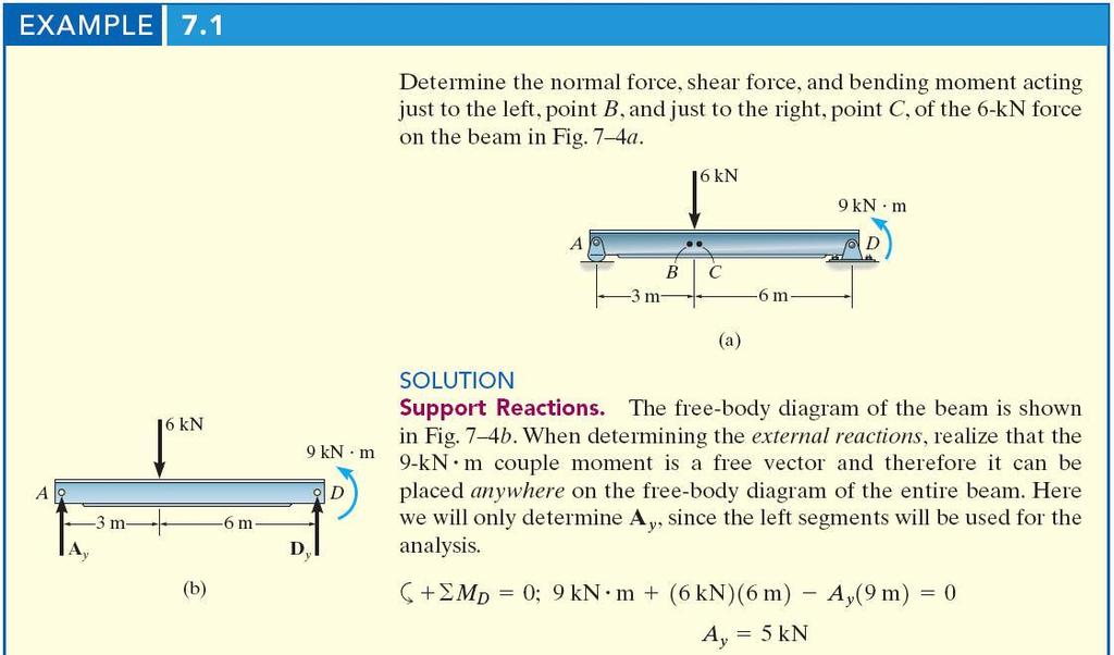
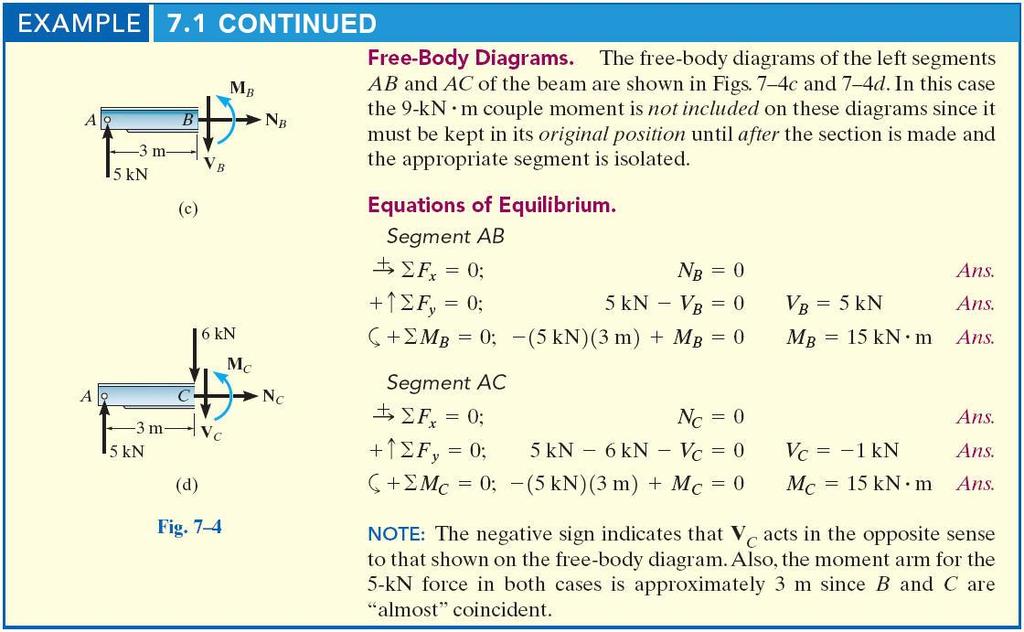
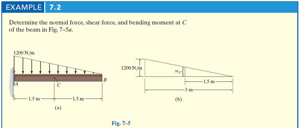
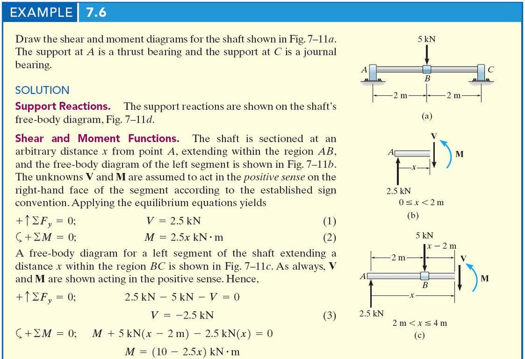
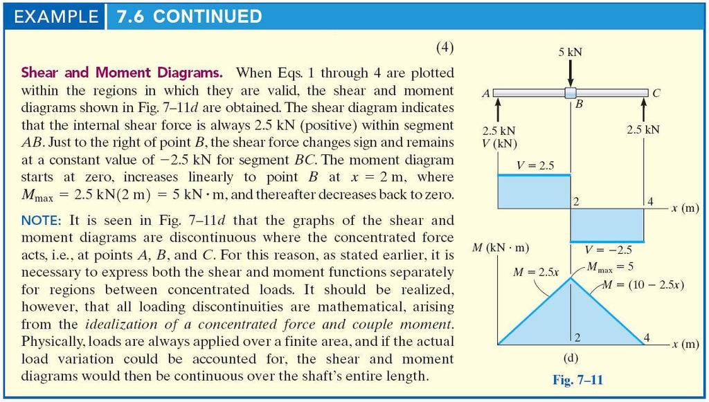
7 Determine the internal normal force, shear force, and moment in the beam at points C and D. Point D is just to the right of the 5-kip load Solution 7

8 Solution Solution 8
9 Solution shear and moment diagrams Shear and moment As noted from the previous analysis, shear and moment vary along the loaded body which was in most of our cases the beam. beams are important element in structure because it can support both shear and moment stresses. The variation in moment and shear can be determined using the method of sections as we learned before. 9
10 shear and moment diagrams Shear and moment However, the values of shear and moment are not changed suddenly when we moves across the point of force action. Therefore, we must develop a method to study this variance with respect to the distances from the supporting points and the points of forces action. Simply, we can assume that the change in shear and moment through the body is a function in terms of body dimensions (mainly in the x-direction) shear and moment diagrams Shear and moment In general, each segment of the loaded body is studied separately and the functions of the shear and moments are determined for the under study segment. The definition of segment is given as: the part of the body that have two consecutive loadings. The type of loading could be concentrated force (single force) or distributed load( f(x)). To illustrate the process of drawing shear and moment diagrams, see the following examples. 10
11 shear and moment diagrams Draw both shear and moment diagrams for the following beam shear and moment diagrams Solution F.B.Ds Equilibrium equations P M A 0 P a P a b Dy 2a b 0 D Fy 0 A D 2P A P y y y y 11
12 [2] Solution Solution Shear and moment diagrams 12
13 13
14 14
15 15
16 16
Chapter 4.1: Shear and Moment Diagram
 Chapter 4.1: Shear and Moment Diagram Chapter 5: Stresses in Beams Chapter 6: Classical Methods Beam Types Generally, beams are classified according to how the beam is supported and according to crosssection
Chapter 7: Internal Forces
 Chapter 7: Internal Forces Chapter Objectives To show how to use the method of sections for determining the internal loadings in a member. To generalize this procedure by formulating equations that can
ENG202 Statics Lecture 16, Section 7.1
 ENG202 Statics Lecture 16, Section 7.1 Internal Forces Developed in Structural Members - Design of any structural member requires an investigation of the loading acting within the member in order to be
Beams. Beams are structural members that offer resistance to bending due to applied load
 Beams Beams are structural members that offer resistance to bending due to applied load 1 Beams Long prismatic members Non-prismatic sections also possible Each cross-section dimension Length of member
MECHANICS OF MATERIALS. Analysis of Beams for Bending
 MECHANICS OF MATERIALS Analysis of Beams for Bending By NUR FARHAYU ARIFFIN Faculty of Civil Engineering & Earth Resources Chapter Description Expected Outcomes Define the elastic deformation of an axially
Chapter 7 INTERNAL FORCES
 Chapter 7 INTERNAL FORCES READING QUIZ 1. In a multiforce member, the member is generally subjected to an internal. A) normal force B) shear force C) bending moment D) All of the above. 2. In mechanics,
Supplement: Statically Indeterminate Frames
 : Statically Indeterminate Frames Approximate Analysis - In this supplement, we consider another approximate method of solving statically indeterminate frames subjected to lateral loads known as the. Like
Supplement: Statically Indeterminate Trusses and Frames
 : Statically Indeterminate Trusses and Frames Approximate Analysis - In this supplement, we consider an approximate method of solving statically indeterminate trusses and frames subjected to lateral loads
- Beams are structural member supporting lateral loadings, i.e., these applied perpendicular to the axes.
 4. Shear and Moment functions - Beams are structural member supporting lateral loadings, i.e., these applied perpendicular to the aes. - The design of such members requires a detailed knowledge of the
Module 2. Analysis of Statically Indeterminate Structures by the Matrix Force Method
 Module 2 Analysis of Statically Indeterminate Structures by the Matrix Force Method Lesson 8 The Force Method of Analysis: Beams Instructional Objectives After reading this chapter the student will be
dv dx Slope of the shear diagram = - Value of applied loading dm dx Slope of the moment curve = Shear Force
 Beams SFD and BMD Shear and Moment Relationships w dv dx Slope of the shear diagram = - Value of applied loading V dm dx Slope of the moment curve = Shear Force Both equations not applicable at the point
[8] Bending and Shear Loading of Beams
![[8] Bending and Shear Loading of Beams](/thumbs/92/110949676.jpg "[8] Bending and Shear Loading of Beams") [8] Bending and Shear Loading of Beams Page 1 of 28 [8] Bending and Shear Loading of Beams [8.1] Bending of Beams (will not be covered in class) [8.2] Bending Strain and Stress [8.3] Shear in Straight
[8] Bending and Shear Loading of Beams Page 1 of 28 [8] Bending and Shear Loading of Beams [8.1] Bending of Beams (will not be covered in class) [8.2] Bending Strain and Stress [8.3] Shear in Straight
6.5 Cables: Concentrated Loads
 6.5 ables: oncentrated Loads 6.5 ables: oncentrated Loads Procedures and Strategies, page 1 of 3 Procedures and Strategies for Solving Problems Involving ables With oncentrated Loads 1. Pass sections through
Chapter 7: Bending and Shear in Simple Beams
 Chapter 7: Bending and Shear in Simple Beams Introduction A beam is a long, slender structural member that resists loads that are generally applied transverse (perpendicular) to its longitudinal axis.
By Dr. Mohammed Ramidh
 Engineering Materials Design Lecture.6 the design of beams By Dr. Mohammed Ramidh 6.1 INTRODUCTION Finding the shear forces and bending moments is an essential step in the design of any beam. we usually
Shear Force and Bending Moment Diagrams for a Beam Steven Vukazich San Jose State University
 Shear Force and Bending oment Diagrams for a Beam Steven ukazich San Jose State University General procedure for the construction of internal force diagrams 1. Find all of the eternal forces and draw the
Beams are bars of material that support. Beams are common structural members. Beams can support both concentrated and distributed loads
 Outline: Review External Effects on Beams Beams Internal Effects Sign Convention Shear Force and Bending Moment Diagrams (text method) Relationships between Loading, Shear Force and Bending Moments (faster
INTERNAL FORCES Today s Objective: Students will be able to: 1. Use the method of sections for determining internal forces in 2-D load cases.
 INTERNAL FORCES Today s Objective: Students will be able to: 1. Use the method of sections for determining internal forces in 2-D load cases. In-Class Activities: Check Homework, if any Reading Quiz Applications
This procedure covers the determination of the moment of inertia about the neutral axis.
 327 Sample Problems Problem 16.1 The moment of inertia about the neutral axis for the T-beam shown is most nearly (A) 36 in 4 (C) 236 in 4 (B) 136 in 4 (D) 736 in 4 This procedure covers the determination
ENGINEERING COUNCIL DIPLOMA LEVEL MECHANICS OF SOLIDS D209 TUTORIAL 3 - SHEAR FORCE AND BENDING MOMENTS IN BEAMS
 ENGINEERING COUNCIL DIPLOMA LEVEL MECHANICS OF SOLIDS D209 TUTORIAL 3 - SHEAR FORCE AND BENDING MOMENTS IN BEAMS You should judge your progress by completing the self assessment exercises. On completion
Types of Structures & Loads
 Structure Analysis I Chapter 4 1 Types of Structures & Loads 1Chapter Chapter 4 Internal lloading Developed in Structural Members Internal loading at a specified Point In General The loading for coplanar
Lecture 15 Strain and stress in beams
 Spring, 2019 ME 323 Mechanics of Materials Lecture 15 Strain and stress in beams Reading assignment: 6.1 6.2 News: Instructor: Prof. Marcial Gonzalez Last modified: 1/6/19 9:42:38 PM Beam theory (@ ME
How Can Motion be Described? and Explained?
 How Can Motion be Described? and Explained? Lesson 14: Torque and the Stability of Structures Stable Structures Explain why structures should be stable. What are the conditions for a structure to be stable?
ENGINEERING SCIENCE H1 OUTCOME 1 - TUTORIAL 2 SHEAR FORCE IN BEAMS EDEXCEL HNC/D ENGINEERING SCIENCE LEVEL 4 H1 FORMERLY UNIT 21718P
 ENGINEERING SCIENCE H1 OUTCOME 1 - TUTORIAL 2 SHEAR FORCE IN BEAMS EDEXCEL HNC/D ENGINEERING SCIENCE LEVEL 4 H1 FORMERLY UNIT 21718P This material is duplicated in the Mechanical Principles module H2 and
Engineering Mechanics Department of Mechanical Engineering Dr. G. Saravana Kumar Indian Institute of Technology, Guwahati
 Engineering Mechanics Department of Mechanical Engineering Dr. G. Saravana Kumar Indian Institute of Technology, Guwahati Module 3 Lecture 6 Internal Forces Today, we will see analysis of structures part
ES120 Spring 2018 Section 7 Notes
 ES120 Spring 2018 Section 7 Notes Matheus Fernandes March 29, 2018 Problem 1: For the beam and loading shown, (a) determine the equations of the shear and bending-moment curves, (b) draw the shear and
Chapter 2: Deflections of Structures
 Chapter 2: Deflections of Structures Fig. 4.1. (Fig. 2.1.) ASTU, Dept. of C Eng., Prepared by: Melkamu E. Page 1 (2.1) (4.1) (2.2) Fig.4.2 Fig.2.2 ASTU, Dept. of C Eng., Prepared by: Melkamu E. Page 2
Stress Engineering Interview Questions Part 1
 Stress Engineering Interview Questions Part 1 Author: Surya Batchu Senior Stress Engineer Founder, STRESS EBOOK LLC. http://www.stressebook.com 1 P a g e Stress Engineering Interview Questions Part 1:
UNIT II 1. Sketch qualitatively the influence line for shear at D for the beam [M/J-15]
![UNIT II 1. Sketch qualitatively the influence line for shear at D for the beam [M/J-15]](/thumbs/95/124878500.jpg "UNIT II 1. Sketch qualitatively the influence line for shear at D for the beam [M/J-15]") UNIT II 1. Sketch qualitatively the influence line for shear at D for the beam [M/J-15] 2. Draw the influence line for shear to the left of B for the overhanging beam shown in Fig. Q. No. 4 [M/J-15] 3.
UNIT II 1. Sketch qualitatively the influence line for shear at D for the beam [M/J-15] 2. Draw the influence line for shear to the left of B for the overhanging beam shown in Fig. Q. No. 4 [M/J-15] 3.
Shear Forces And Bending Moments
 Shear Forces And Bending Moments 1 Introduction 2001 Brooks/Cole, a division of Thomson Learning, Inc. Thomson Learning is a trademark used herein under license. Fig. 4-1 Examples of beams subjected to
Problem d d d B C E D. 0.8d. Additional lecturebook examples 29 ME 323
 Problem 9.1 Two beam segments, AC and CD, are connected together at C by a frictionless pin. Segment CD is cantilevered from a rigid support at D, and segment AC has a roller support at A. a) Determine
PURE BENDING. If a simply supported beam carries two point loads of 10 kn as shown in the following figure, pure bending occurs at segment BC.
 BENDING STRESS The effect of a bending moment applied to a cross-section of a beam is to induce a state of stress across that section. These stresses are known as bending stresses and they act normally
Mechanics of Materials
 Mechanics of Materials 2. Introduction Dr. Rami Zakaria References: 1. Engineering Mechanics: Statics, R.C. Hibbeler, 12 th ed, Pearson 2. Mechanics of Materials: R.C. Hibbeler, 9 th ed, Pearson 3. Mechanics
EDEXCEL NATIONAL CERTIFICATE/DIPLOMA FURTHER MECHANICAL PRINCIPLES AND APPLICATIONS UNIT 11 - NQF LEVEL 3 OUTCOME 1 - FRAMES AND BEAMS
 EDEXCEL NATIONAL CERTIFICATE/DIPLOMA FURTHER MECHANICAL PRINCIPLES AND APPLICATIONS UNIT 11 - NQF LEVEL 3 OUTCOME 1 - FRAMES AND BEAMS TUTORIAL 2 - BEAMS CONTENT Be able to determine the forces acting
Moment Distribution Method
 Moment Distribution Method Lesson Objectives: 1) Identify the formulation and sign conventions associated with the Moment Distribution Method. 2) Derive the Moment Distribution Method equations using mechanics
Unit Workbook 1 Level 4 ENG U8 Mechanical Principles 2018 UniCourse Ltd. All Rights Reserved. Sample
 Pearson BTEC Levels 4 Higher Nationals in Engineering (RQF) Unit 8: Mechanical Principles Unit Workbook 1 in a series of 4 for this unit Learning Outcome 1 Static Mechanical Systems Page 1 of 23 1.1 Shafts
ISHIK UNIVERSITY DEPARTMENT OF MECHATRONICS ENGINEERING
 ISHIK UNIVERSITY DEPARTMENT OF MECHATRONICS ENGINEERING QUESTION BANK FOR THE MECHANICS OF MATERIALS-I 1. A rod 150 cm long and of diameter 2.0 cm is subjected to an axial pull of 20 kn. If the modulus
Chapter 2. Shear Force and Bending Moment. After successfully completing this chapter the students should be able to:
 Chapter Shear Force and Bending Moment This chapter begins with a discussion of beam types. It is also important for students to know and understand the reaction from the types of supports holding the
SIGN CONVENTION OF STRESS RESULTANTS
 SIGN CONVENTION OF STRESS RESULTANTS A quick guide to understanding the sign conventions used in the ush Me ull Me models National HE STEM rogramme INTRODUCTION Representing stress resultants graphically
Continuing Education Course #207 What Every Engineer Should Know About Structures Part B Statics Applications
 1 of 6 Continuing Education Course #207 What Every Engineer Should Know About Structures Part B Statics Applications 1. As a practical matter, determining design loads on structural members involves several
7 TRANSVERSE SHEAR transverse shear stress longitudinal shear stresses
 7 TRANSVERSE SHEAR Before we develop a relationship that describes the shear-stress distribution over the cross section of a beam, we will make some preliminary remarks regarding the way shear acts within
MECE 3321: Mechanics of Solids Chapter 6
 MECE 3321: Mechanics of Solids Chapter 6 Samantha Ramirez Beams Beams are long straight members that carry loads perpendicular to their longitudinal axis Beams are classified by the way they are supported
Stress Analysis Lecture 4 ME 276 Spring Dr./ Ahmed Mohamed Nagib Elmekawy
 Stress Analysis Lecture 4 ME 76 Spring 017-018 Dr./ Ahmed Mohamed Nagib Elmekawy Shear and Moment Diagrams Beam Sign Convention The positive directions are as follows: The internal shear force causes a
8-5 Conjugate-Beam method. 8-5 Conjugate-Beam method. 8-5 Conjugate-Beam method. 8-5 Conjugate-Beam method
 The basis for the method comes from the similarity of eqn.1 &. to eqn 8. & 8. To show this similarity, we can write these eqn as shown dv dx w d θ M dx d M w dx d v M dx Here the shear V compares with
Chapter Objectives. Copyright 2011 Pearson Education South Asia Pte Ltd
 Chapter Objectives To generalize the procedure by formulating equations that can be plotted so that they describe the internal shear and moment throughout a member. To use the relations between distributed
Properties of Sections
 ARCH 314 Structures I Test Primer Questions Dr.-Ing. Peter von Buelow Properties of Sections 1. Select all that apply to the characteristics of the Center of Gravity: A) 1. The point about which the body
MECHANICS OF MATERIALS. Prepared by Engr. John Paul Timola
 MECHANICS OF MATERIALS Prepared by Engr. John Paul Timola Mechanics of materials branch of mechanics that studies the internal effects of stress and strain in a solid body. stress is associated with the
Determinate portal frame
 eterminate portal frame onsider the frame shown in the figure below with the aim of calculating the bending moment diagram (M), shear force diagram (SF), and axial force diagram (F). P H y R x x R y L
BEAM A horizontal or inclined structural member that is designed to resist forces acting to its axis is called a beam
 BEM horizontal or inclined structural member that is designed to resist forces acting to its axis is called a beam INTERNL FORCES IN BEM Whether or not a beam will break, depend on the internal resistances
TYPES OF STRUCUTRES. HD in Civil Engineering Page 1-1
 E2027 Structural nalysis I TYPES OF STRUUTRES H in ivil Engineering Page 1-1 E2027 Structural nalysis I SUPPORTS Pin or Hinge Support pin or hinge support is represented by the symbol H or H V V Prevented:
Strength of Materials Prof. S.K.Bhattacharya Dept. of Civil Engineering, I.I.T., Kharagpur Lecture No.26 Stresses in Beams-I
 Strength of Materials Prof. S.K.Bhattacharya Dept. of Civil Engineering, I.I.T., Kharagpur Lecture No.26 Stresses in Beams-I Welcome to the first lesson of the 6th module which is on Stresses in Beams
Chapter 7 FORCES IN BEAMS AND CABLES
 hapter 7 FORES IN BEAMS AN ABLES onsider a straight two-force member AB subjected at A and B to equal and opposite forces F and -F directed along AB. utting the member AB at and drawing the free-body B
Chapter 5 Elastic Strain, Deflection, and Stability 1. Elastic Stress-Strain Relationship
 Chapter 5 Elastic Strain, Deflection, and Stability Elastic Stress-Strain Relationship A stress in the x-direction causes a strain in the x-direction by σ x also causes a strain in the y-direction & z-direction
6/6/2008. Qualitative Influence Lines for Statically Indeterminate Structures: Muller-Breslau s Principle
 Qualitative Influence Lines for Statically Indeterminate Structures: Muller-Breslau s Principle The influence line for a force (or moment) response function is given by the deflected shape of the released
If the number of unknown reaction components are equal to the number of equations, the structure is known as statically determinate.
 1 of 6 EQUILIBRIUM OF A RIGID BODY AND ANALYSIS OF ETRUCTURAS II 9.1 reactions in supports and joints of a two-dimensional structure and statically indeterminate reactions: Statically indeterminate structures
CIV100 Mechanics. Module 5: Internal Forces and Design. by: Jinyue Zhang. By the end of this Module you should be able to:
 CIV100 Mechanics Module 5: Internal Forces and Design by: Jinyue Zhang Module Objective By the end of this Module you should be able to: Find internal forces of any structural members Understand how Shear
Shear force and bending moment of beams 2.1 Beams 2.2 Classification of beams 1. Cantilever Beam Built-in encastre' Cantilever
 CHAPTER TWO Shear force and bending moment of beams 2.1 Beams A beam is a structural member resting on supports to carry vertical loads. Beams are generally placed horizontally; the amount and extent of
Methods of Analysis. Force or Flexibility Method
 INTRODUCTION: The structural analysis is a mathematical process by which the response of a structure to specified loads is determined. This response is measured by determining the internal forces or stresses
Equilibrium of a Particle
 ME 108 - Statics Equilibrium of a Particle Chapter 3 Applications For a spool of given weight, what are the forces in cables AB and AC? Applications For a given weight of the lights, what are the forces
8.3 Shear and Bending-Moment Diagrams Constructed by Areas
 8.3 Shear and ending-moment Diagrams Constructed by reas 8.3 Shear and ending-moment Diagrams Constructed by reas Procedures and Strategies, page 1 of 3 Procedures and Strategies for Solving Problems Involving
WORCESTER POLYTECHNIC INSTITUTE
 WORCESTER POLYTECHNIC INSTITUTE MECHANICAL ENGINEERING DEPARTMENT STRESS ANALYSIS ES-2502, C 2012 Lecture 02: Internal Forces 13 January 2012 General information Instructor: Cosme Furlong HL-151 (508)
P.E. Civil Exam Review:
 P.E. Civil Exam Review: Structural Analysis J.P. Mohsen Email: jpm@louisville.edu Structures Determinate Indeterminate STATICALLY DETERMINATE STATICALLY INDETERMINATE Stability and Determinacy of Trusses
Structural Analysis III Compatibility of Displacements & Principle of Superposition
 Structural Analysis III Compatibility of Displacements & Principle of Superposition 2007/8 Dr. Colin Caprani, Chartered Engineer 1 1. Introduction 1.1 Background In the case of 2-dimensional structures
Finite Element Analysis Prof. Dr. B. N. Rao Department of Civil Engineering Indian Institute of Technology, Madras. Module - 01 Lecture - 11
 Finite Element Analysis Prof. Dr. B. N. Rao Department of Civil Engineering Indian Institute of Technology, Madras Module - 01 Lecture - 11 Last class, what we did is, we looked at a method called superposition
CHAPTER -6- BENDING Part -1-
 Ishik University / Sulaimani Civil Engineering Department Mechanics of Materials CE 211 CHAPTER -6- BENDING Part -1-1 CHAPTER -6- Bending Outlines of this chapter: 6.1. Chapter Objectives 6.2. Shear and
BTECH MECHANICAL PRINCIPLES AND APPLICATIONS. Level 3 Unit 5
 BTECH MECHANICAL PRINCIPLES AND APPLICATIONS Level 3 Unit 5 FORCES AS VECTORS Vectors have a magnitude (amount) and a direction. Forces are vectors FORCES AS VECTORS (2 FORCES) Forces F1 and F2 are in
Mechanics of Materials CIVL 3322 / MECH 3322
 Mechanics of Materials CIVL 3322 / MECH 3322 2 3 4 5 6 7 8 9 10 A Quiz 11 A Quiz 12 A Quiz 13 A Quiz 14 A Quiz 15 A Quiz 16 In Statics, we spent most of our time looking at reactions at supports Two variations
SAB2223 Mechanics of Materials and Structures
 S2223 Mechanics of Materials and Structures TOPIC 2 SHER FORCE ND ENDING MOMENT Lecturer: Dr. Shek Poi Ngian TOPIC 2 SHER FORCE ND ENDING MOMENT Shear Force and ending Moment Introduction Types of beams
OUT ON A LIMB AND HUNG OUT TO DRY :
 27-Nov-12 17:03 1 of 2 h p://edugen.wileyplus.com/edugen/courses/crs1404/pc/c10/c2hlchbhcmq3mjewyzewxzeuegzvcm0.enc?course=crs1404&id=ref CHAPTER 10 OUT ON A LIMB AND HUNG OUT TO DRY : A LOOK AT INTERNAL
ENG2000 Chapter 7 Beams. ENG2000: R.I. Hornsey Beam: 1
 ENG2000 Chapter 7 Beams ENG2000: R.I. Hornsey Beam: 1 Overview In this chapter, we consider the stresses and moments present in loaded beams shear stress and bending moment diagrams We will also look at
MAAE 2202 A. Come to the PASS workshop with your mock exam complete. During the workshop you can work with other students to review your work.
 It is most beneficial to you to write this mock final exam UNDER EXAM CONDITIONS. This means: Complete the exam in 3 hours. Work on your own. Keep your textbook closed. Attempt every question. After the
MECHANICS OF MATERIALS
 MM 210 MECHANICS OF MATERIALS 2012-2013 1 1.INTRODUCTION TO MECHANICS OF MATERIALS WHAT IS MECHANICS OF MATERIALS? Mechanics is the physical science that deals with the conditions of rest or motion of
Levers of the Musculoskeletal System
 Levers of the Musculoskeletal System Lever system consists of: lever fulcrum load force Three classes of levers 1. first class (a) - pry bars, crowbars 2. second class (b) - wheelbarrow 3. third class
CH. 4 BEAMS & COLUMNS
 CH. 4 BEAMS & COLUMNS BEAMS Beams Basic theory of bending: internal resisting moment at any point in a beam must equal the bending moments produced by the external loads on the beam Rx = Cc + Tt - If the
Preliminaries: Beam Deflections Virtual Work
 Preliminaries: Beam eflections Virtual Work There are several methods available to calculate deformations (displacements and rotations) in beams. They include: Formulating moment equations and then integrating
ES230 STRENGTH OF MATERIALS
 ES230 STRENGTH OF MATERIALS Exam 1 Study Guide. Exam 1: Wednesday, February 8 th, in-class Updated 2/5/17 Purpose of this Guide: To thoroughly prepare students for the exact types of problems that will
OUTCOME 1 - TUTORIAL 3 BENDING MOMENTS. You should judge your progress by completing the self assessment exercises. CONTENTS
 Unit 2: Unit code: QCF Level: 4 Credit value: 15 Engineering Science L/601/1404 OUTCOME 1 - TUTORIAL 3 BENDING MOMENTS 1. Be able to determine the behavioural characteristics of elements of static engineering
Quizzam Module 1 : Statics
 Structural Steel Design Quizzam odule : Statics NAE Draw shear and moment diagrams for the following loading conditions. Note the reactions. Calculate the maximum amount of internal bending moment. 0 500
Portal Frame Calculations Lateral Loads
 Portal Frame Calculations Lateral Loads Consider the following multi-story frame: The portal method makes several assumptions about the internal forces of the columns and beams in a rigid frame: 1) Inflection
CHAPTER 6: Shearing Stresses in Beams
 (130) CHAPTER 6: Shearing Stresses in Beams When a beam is in pure bending, the only stress resultants are the bending moments and the only stresses are the normal stresses acting on the cross sections.
STRESS STRAIN AND DEFORMATION OF SOLIDS, STATES OF STRESS
 1 UNIT I STRESS STRAIN AND DEFORMATION OF SOLIDS, STATES OF STRESS 1. Define: Stress When an external force acts on a body, it undergoes deformation. At the same time the body resists deformation. The
Deflections. Deflections. Deflections. Deflections. Deflections. Deflections. dx dm V. dx EI. dx EI dx M. dv w
 CIVL 311 - Conjugate eam 1/5 Conjugate beam method The development of the conjugate beam method has been atributed to several strucutral engineers. any credit Heinrich üller-reslau (1851-195) with the
Mechanics in Energy Resources Engineering - Chapter 5 Stresses in Beams (Basic topics)
") Week 7, 14 March Mechanics in Energy Resources Engineering - Chapter 5 Stresses in Beams (Basic topics) Ki-Bok Min, PhD Assistant Professor Energy Resources Engineering i Seoul National University Shear
Week 7, 14 March Mechanics in Energy Resources Engineering - Chapter 5 Stresses in Beams (Basic topics) Ki-Bok Min, PhD Assistant Professor Energy Resources Engineering i Seoul National University Shear
REVIEW FOR EXAM II. Dr. Ibrahim A. Assakkaf SPRING 2002
 REVIEW FOR EXM II. J. Clark School of Engineering Department of Civil and Environmental Engineering b Dr. Ibrahim. ssakkaf SPRING 00 ENES 0 Mechanics of Materials Department of Civil and Environmental
FME201 Solid & Structural Mechanics I
 FME201 Solid & Structural Mechanics I Dr.Hussein Jama Hussein.jama@uobi.ac.ke Office 414 Lecture: Mon 11am -1pm (E207) Tutorial Tue 12-1pm (E207) 10/1/2013 1 Outline This lecture is based on chapter 1
Shear Force V: Positive shear tends to rotate the segment clockwise.
 INTERNL FORCES IN EM efore a structural element can be designed, it is necessary to determine the internal forces that act within the element. The internal forces for a beam section will consist of a shear
Sports biomechanics explores the relationship between the body motion, internal forces and external forces to optimize the sport performance.
 What is biomechanics? Biomechanics is the field of study that makes use of the laws of physics and engineering concepts to describe motion of body segments, and the internal and external forces, which
MAHALAKSHMI ENGINEERING COLLEGE
 CE840-STRENGTH OF TERIS - II PGE 1 HKSHI ENGINEERING COEGE TIRUCHIRPI - 611. QUESTION WITH NSWERS DEPRTENT : CIVI SEESTER: IV SU.CODE/ NE: CE 840 / Strength of aterials -II UNIT INDETERINTE ES 1. Define
Calculus and Structures
 Calculus and Structures CHAPTER 8 SHEAR FORCE AND BENDING MOMENTS FOR BEAMS WITH CONTINUOUS FORCES Calculus and Structures 11 Copyright Chapter 8 CONTINUOUS FORCE 8.1 INTRODUCTION The last section was
Part 1 is to be completed without notes, beam tables or a calculator. DO NOT turn Part 2 over until you have completed and turned in Part 1.
 NAME CM 3505 Fall 06 Test 2 Part 1 is to be completed without notes, beam tables or a calculator. Part 2 is to be completed after turning in Part 1. DO NOT turn Part 2 over until you have completed and
five moments ELEMENTS OF ARCHITECTURAL STRUCTURES: FORM, BEHAVIOR, AND DESIGN DR. ANNE NICHOLS SPRING 2014 lecture ARCH 614
 ELEMENTS OF ARCHITECTURAL STRUCTURES: FORM, BEHAVIOR, AND DESIGN DR. ANNE NICHOLS SPRING 2014 lecture five moments Moments 1 Moments forces have the tendency to make a body rotate about an axis http://www.physics.umd.edu
Stresses in Curved Beam
 Stresses in Curved Beam Consider a curved beam subjected to bending moment M b as shown in the figure. The distribution of stress in curved flexural member is determined by using the following assumptions:
Strength of Materials Prof. Dr. Suraj Prakash Harsha Mechanical and Industrial Engineering Department Indian Institute of Technology, Roorkee
 Strength of Materials Prof. Dr. Suraj Prakash Harsha Mechanical and Industrial Engineering Department Indian Institute of Technology, Roorkee Lecture - 28 Hi, this is Dr. S. P. Harsha from Mechanical and
276 Calculus and Structures
 76 Calculus and Structures CHAPTER THE CONJUGATE BEA ETHOD Calculus and Structures 77 Copyright Chapter THE CONJUGATE BEA ETHOD.1 INTRODUCTION To find the deflection of a beam you must solve the equation,
7.4 The Elementary Beam Theory
 7.4 The Elementary Beam Theory In this section, problems involving long and slender beams are addressed. s with pressure vessels, the geometry of the beam, and the specific type of loading which will be
Name (Print) ME Mechanics of Materials Exam # 2 Date: March 29, 2017 Time: 8:00 10:00 PM - Location: WTHR 200
 ME Mechanics of Materials Exam # 2 Date: March 29, 2017 Time: 8:00 10:00 PM - Location: WTHR 200") Name (Print) (Last) (First) Instructions: ME 323 - Mechanics of Materials Exam # 2 Date: Time: 8:00 10:00 PM - Location: WTHR 200 Circle your lecturer s name and your class meeting time. Koslowski Zhao
Name (Print) (Last) (First) Instructions: ME 323 - Mechanics of Materials Exam # 2 Date: Time: 8:00 10:00 PM - Location: WTHR 200 Circle your lecturer s name and your class meeting time. Koslowski Zhao
Static equilibrium. Objectives. Physics terms. Assessment. Brainstorm. Equations 6/3/14
 Static equilibrium Objectives State the conditions of static equilibrium in terms of forces and torques. Draw a free-body diagram of a lever showing all forces. Use the condition of equilibrium to solve
Stress Transformation Equations: u = +135 (Fig. a) s x = 80 MPa s y = 0 t xy = 45 MPa. we obtain, cos u + t xy sin 2u. s x = s x + s y.
 s x = 80 MPa s y = 0 t xy = 45 MPa. we obtain, cos u + t xy sin 2u. s x = s x + s y.") 014 Pearson Education, Inc., Upper Saddle River, NJ. All rights reserved. This material is protected under all copyright laws as they currently 9 7. Determine the normal stress and shear stress acting
014 Pearson Education, Inc., Upper Saddle River, NJ. All rights reserved. This material is protected under all copyright laws as they currently 9 7. Determine the normal stress and shear stress acting
Lecture 23 March 12, 2018 Chap 7.3
 Statics - TAM 210 & TAM 211 Lecture 23 March 12, 2018 Chap 7.3 Announcements Upcoming deadlines: Monday (3/12) Mastering Engineering Tutorial 9 Tuesday (3/13) PL HW 8 Quiz 5 (3/14-16) Sign up at CBTF Up
Members Subjected to Combined Loads
 Members Subjected to Combined Loads Combined Bending & Twisting : In some applications the shaft are simultaneously subjected to bending moment M and Torque T.The Bending moment comes on the shaft due