UNIT II 1. Sketch qualitatively the influence line for shear at D for the beam [M/J-15]
|
|
|
- Darcy McDonald
- 5 years ago
- Views:
Transcription
1 UNIT II 1. Sketch qualitatively the influence line for shear at D for the beam [M/J-15] 2. Draw the influence line for shear to the left of B for the overhanging beam shown in Fig. Q. No. 4 [M/J-15]
2 3. State the position of loading for maximum bending moment at a point in a simply supported beam when it subjected to a series of moving point loads. [M/J-16] When a series of point loads crosses a simply supported beam, the absolute maximum bending moment will occur near midspan under the load Wcr, where Wcr is the maximum load in a series of point loads 4. Draw influence line for shearing force at any point in a simply supported beam using Muller Breslau s principle. [M/J-16] 5. What is the use of influence line diagram (ILD)? [A/M 12] Influence lines are very useful in the quick determination of reactions, shear force, bending moment or similar functions at a given section under any given system of moving loads. Influence lines are useful in determining the load position to cause maximum value of a given function in a structure on which load positions can vary. 6. State Muller Breslau s principle. [N/D 12,13,14] Muller-Breslau principle states that, if we want to sketch the influence line for any force quantity (like thrust, shear, reaction, support moment or bending moment) in a structure, We remove from the structure the resistant to that force quantity and We apply on the remaining structure a unit displacement corresponding to that force quantity. 7. What are influence lines? [N/D - 12, M/J - 14] An influence line is a graph showing, for any given frame or truss, the variation of any force or displacement quantity (such as shear force, bending moment, tension, deflection) for all positions of a moving unit load as it crosses the structure from one end to the other. 8. Explain the use of Beggs deformeter. [A/M 11] It permits extremely accurate work in indirect model analysis.
3 For best results the deformeter should be used in a room with controlled temperature and humidity so as to avoid disturbance of model deflections due to differential heating. Extended periods of use of this deformeter may cause considerable eye strain. 9. What are the uses of influence lines? [N/D-16] An influence line is a graph showing, for any given frame or truss, the variation of any force or displacement quantity (such as shear force, bending moment, tension, deflection) for all positions of a moving unit load as it crosses the structure from one end to the other. 10. State: Muller Breslau s principle. [N/D-16][N/D-12 & 13, A/M-12, M/J-14] Muller-Breslau principle states that, if we want to sketch the influence line for any force quantity (like thrust, shear, reaction, support moment or bending moment) in a structure, We remove from the structure the resistant to that force quantity and We apply on the remaining structure a unit displacement corresponding to that force quantity
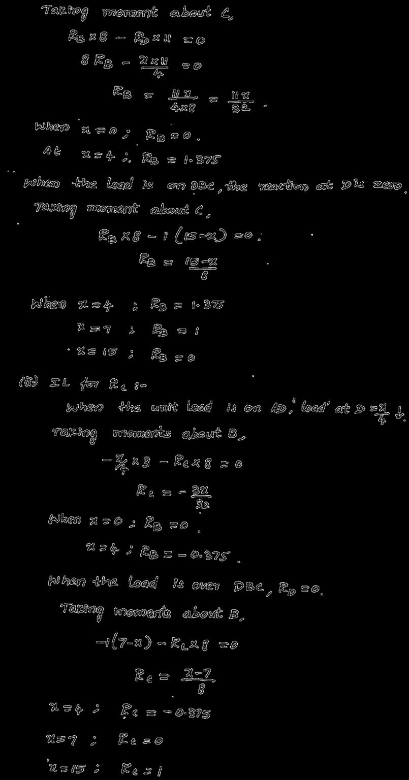
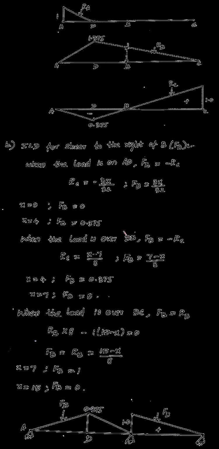
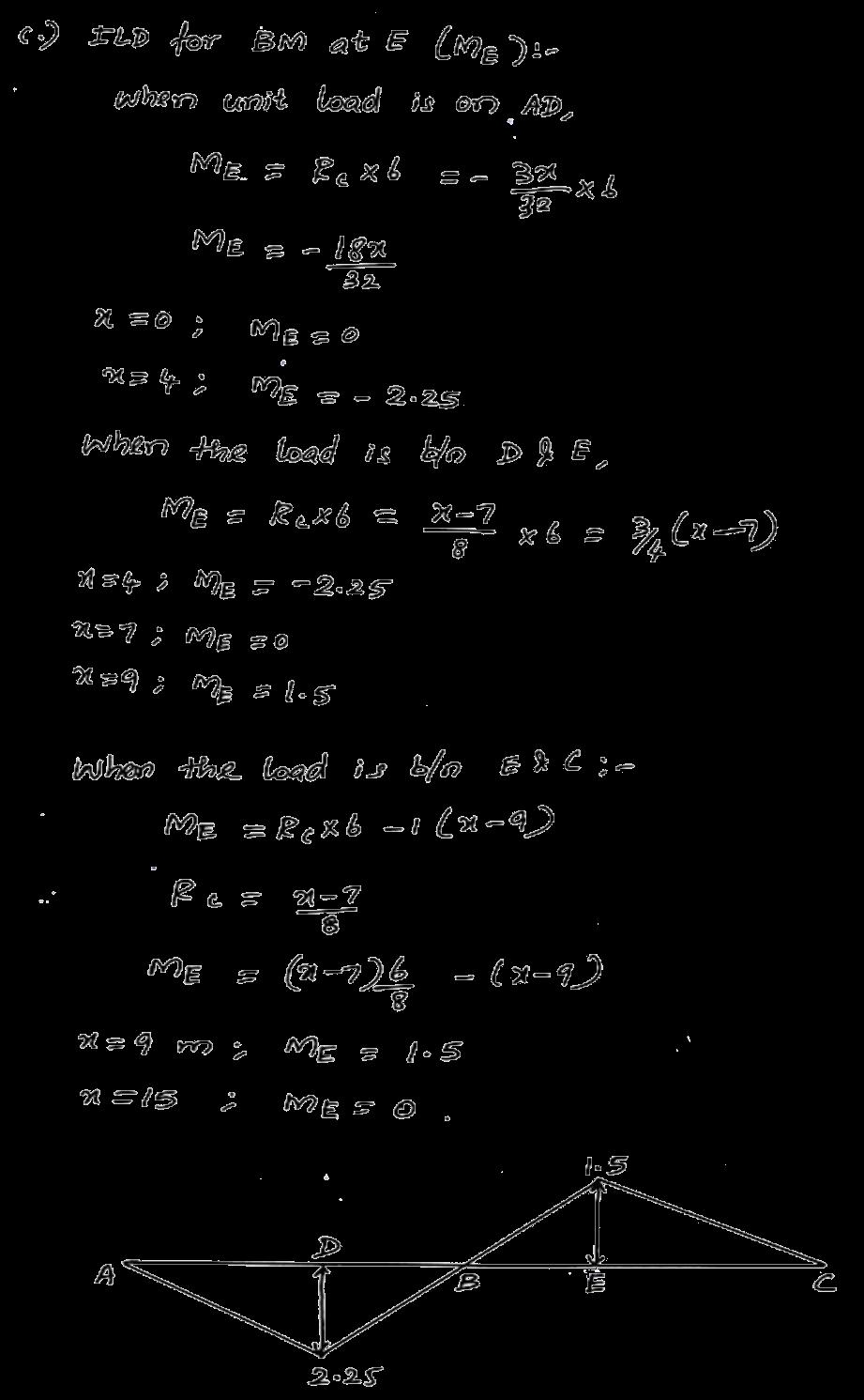
4 1. (a) Using Muller Breslau principle, draw the influence line for the bending moment at D, the middle point of span AB of a continuous beam shown Fig. Q. No. 12(a). Compute then ordinates at 1m interval. Determine the maximum hogging bending moment in the beam when two concentrate loads of 8 kn each and separated by a distance 1 m passes though the beam from left to right. [M/J-15][N/D-11]
5
6
7
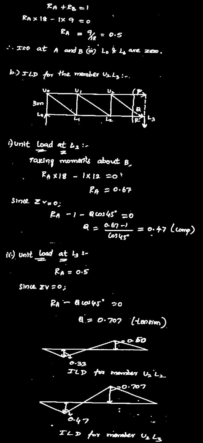
8 2. (b)draw the IL for force in member BC and CI for the truss shown in Figure Q. No. 12(b). The height of the truss in 9 m and each segment is 9 m long. [M/J-15][N/D-11][N/D-10]
9

10 3. (a) A train of loads as shown in Fig. Q. 12 (a) crosses a simply supported beam of 24 m span from left to right. Using influence line determine the maximum bending moment at left one third span point and also the absolute maximum bending moment in the beam. SOLUTION STEP 1: [M/J-16][N/D-13]
11
12 STEP 3:
13 4. (b)a Continuous beam ABC is simply resting on supports A and C, and continuous over the support B. The span AB is 6 m and the span BC is 8 m. Draw the influence line diagram for moment at B. Assume Flexural rigidity is constant throughout and calculate the influence line ordinates at 2 m intervals. [M/J-16]
14

15
16 5. (a) A continuous beam ABC is simply resting on supports A and C. Contiuous over the support B and has an internal hinge (D) at 3 m from A. The span AB is 7 m and the span BC is 10 m. Draw influence lines for reactions at A and B. [N/D-16]

17 6. (b)draw influence line for shearing force at 4m from the propped end of a propped cantilever of span 7m. Calculate the ordinates at every 1m. [N/D-16]
18

19 7. A live load of 15 kn/m, 5 m long moves on a girder simply supported on a span of 13 m. Find the maximum bending moment that can occur at a section 6 m from the left end. [ N/D- 12, M/J- 14]

20 8. Explain the procedure and applications of Beggs deformeter. [ M/J-14]
21
22
 SRI VIDYA COLLEGE OF ENGINEERING AND TECHNOLOGY, VIRUDHUNAGAR CE 6602 STRUCTURAL ANALYSIS - II DEPARTMENT OF CIVIL ENGINEERING CE 6501 STRUCTURAL ANALYSIS - I 2 MARK QUESTION BANK UNIT II - INFLUENCE LINES
UNIT-II MOVING LOADS AND INFLUENCE LINES
 UNIT-II MOVING LOADS AND INFLUENCE LINES Influence lines for reactions in statically determinate structures influence lines for member forces in pin-jointed frames Influence lines for shear force and bending
 techie-touch.blogspot.com DEPARTMENT OF CIVIL ENGINEERING ANNA UNIVERSITY QUESTION BANK CE 2302 STRUCTURAL ANALYSIS-I TWO MARK QUESTIONS UNIT I DEFLECTION OF DETERMINATE STRUCTURES 1. Write any two important
CE 2302 STRUCTURAL ANALYSIS I UNIT-I DEFLECTION OF DETERMINATE STRUCTURES
 CE 2302 STRUCTURAL ANALYSIS I UNIT-I DEFLECTION OF DETERMINATE STRUCTURES 1.Why is it necessary to compute deflections in structures? Computation of deflection of structures is necessary for the following
Chapter 4.1: Shear and Moment Diagram
 Chapter 4.1: Shear and Moment Diagram Chapter 5: Stresses in Beams Chapter 6: Classical Methods Beam Types Generally, beams are classified according to how the beam is supported and according to crosssection
INFLUENCE LINE. Structural Analysis. Reference: Third Edition (2005) By Aslam Kassimali
 By Aslam Kassimali") INFLUENCE LINE Reference: Structural Analsis Third Edition (2005) B Aslam Kassimali DEFINITION An influence line is a graph of a response function of a structure as a function of the position of a downward
INFLUENCE LINE Reference: Structural Analsis Third Edition (2005) B Aslam Kassimali DEFINITION An influence line is a graph of a response function of a structure as a function of the position of a downward
BEAM A horizontal or inclined structural member that is designed to resist forces acting to its axis is called a beam
 BEM horizontal or inclined structural member that is designed to resist forces acting to its axis is called a beam INTERNL FORCES IN BEM Whether or not a beam will break, depend on the internal resistances
UNIT I. S.NO 2 MARKS PAGE NO 1 Why it is necessary to compute deflections in structures? 4 2 What is meant by cambering technique, in structures?
 1 UNIT I UNIT I INDETERMINATE FRAMES 9 Degree of static and kinematic indeterminacies for plane frames - analysis of indeterminate pin-jointed frames - rigid frames (Degree of statical indeterminacy up
6/6/2008. Qualitative Influence Lines for Statically Indeterminate Structures: Muller-Breslau s Principle
 Qualitative Influence Lines for Statically Indeterminate Structures: Muller-Breslau s Principle The influence line for a force (or moment) response function is given by the deflected shape of the released
QUESTION BANK. SEMESTER: V SUBJECT CODE / Name: CE 6501 / STRUCTURAL ANALYSIS-I
 QUESTION BANK DEPARTMENT: CIVIL SEMESTER: V SUBJECT CODE / Name: CE 6501 / STRUCTURAL ANALYSIS-I Unit 5 MOMENT DISTRIBUTION METHOD PART A (2 marks) 1. Differentiate between distribution factors and carry
Module 2. Analysis of Statically Indeterminate Structures by the Matrix Force Method
 Module 2 Analysis of Statically Indeterminate Structures by the Matrix Force Method Lesson 8 The Force Method of Analysis: Beams Instructional Objectives After reading this chapter the student will be
Moment Distribution Method
 Moment Distribution Method Lesson Objectives: 1) Identify the formulation and sign conventions associated with the Moment Distribution Method. 2) Derive the Moment Distribution Method equations using mechanics
Ph.D. Preliminary Examination Analysis
 UNIVERSITY OF CALIFORNIA, BERKELEY Spring Semester 2017 Dept. of Civil and Environmental Engineering Structural Engineering, Mechanics and Materials Name:......................................... Ph.D.
CIVIL DEPARTMENT MECHANICS OF STRUCTURES- ASSIGNMENT NO 1. Brach: CE YEAR:
 MECHANICS OF STRUCTURES- ASSIGNMENT NO 1 SEMESTER: V 1) Find the least moment of Inertia about the centroidal axes X-X and Y-Y of an unequal angle section 125 mm 75 mm 10 mm as shown in figure 2) Determine
29. Define Stiffness matrix method. 30. What is the compatibility condition used in the flexibility method?
 CLASS: III YEAR / VI SEMESTER CIVIL SUBJECTCODE AND NAME: CE 2351 - STRUCTURAL ANALYSIS-II UNIT1 FLEXIBILITY MATRIX METHOD. PART A 1. What is meant by indeterminate structures? 2. What are the conditions
Module 3. Analysis of Statically Indeterminate Structures by the Displacement Method
 odule 3 Analysis of Statically Indeterminate Structures by the Displacement ethod Lesson 16 The Slope-Deflection ethod: rames Without Sidesway Instructional Objectives After reading this chapter the student
Ph.D. Preliminary Examination Analysis
 UNIVERSITY OF CALIFORNIA, BERKELEY Spring Semester 2014 Dept. of Civil and Environmental Engineering Structural Engineering, Mechanics and Materials Name:......................................... Ph.D.
UNIT IV FLEXIBILTY AND STIFFNESS METHOD
 SIDDHARTH GROUP OF INSTITUTIONS :: PUTTUR Siddharth Nagar, Narayanavanam Road 517583 QUESTION BANK (DESCRIPTIVE) Subject with Code : SA-II (13A01505) Year & Sem: III-B.Tech & I-Sem Course & Branch: B.Tech
CHENDU COLLEGE OF ENGINEERING &TECHNOLOGY DEPARTMENT OF CIVIL ENGINEERING SUB CODE & SUB NAME : CE2351-STRUCTURAL ANALYSIS-II UNIT-1 FLEXIBILITY
 CHENDU COLLEGE OF ENGINEERING &TECHNOLOGY DEPARTMENT OF CIVIL ENGINEERING SUB CODE & SUB NAME : CE2351-STRUCTURAL ANALYSIS-II UNIT-1 FLEXIBILITY METHOD FOR INDETERMINATE FRAMES PART-A(2MARKS) 1. What is
3 Hours/100 Marks Seat No.
 *17304* 17304 14115 3 Hours/100 Marks Seat No. Instructions : (1) All questions are compulsory. (2) Illustrate your answers with neat sketches wherever necessary. (3) Figures to the right indicate full
2. Determine the deflection at C of the beam given in fig below. Use principal of virtual work. W L/2 B A L C
 CE-1259, Strength of Materials UNIT I STRESS, STRAIN DEFORMATION OF SOLIDS Part -A 1. Define strain energy density. 2. State Maxwell s reciprocal theorem. 3. Define proof resilience. 4. State Castigliano
M.S Comprehensive Examination Analysis
 UNIVERSITY OF CALIFORNIA, BERKELEY Spring Semester 2014 Dept. of Civil and Environmental Engineering Structural Engineering, Mechanics and Materials Name:......................................... M.S Comprehensive
Deflection of Flexural Members - Macaulay s Method 3rd Year Structural Engineering
 Deflection of Flexural Members - Macaulay s Method 3rd Year Structural Engineering 008/9 Dr. Colin Caprani 1 Contents 1. Introduction... 3 1.1 General... 3 1. Background... 4 1.3 Discontinuity Functions...
Shear force and bending moment of beams 2.1 Beams 2.2 Classification of beams 1. Cantilever Beam Built-in encastre' Cantilever
 CHAPTER TWO Shear force and bending moment of beams 2.1 Beams A beam is a structural member resting on supports to carry vertical loads. Beams are generally placed horizontally; the amount and extent of
Deflection of Flexural Members - Macaulay s Method 3rd Year Structural Engineering
 Deflection of Flexural Members - Macaulay s Method 3rd Year Structural Engineering 009/10 Dr. Colin Caprani 1 Contents 1. Introduction... 4 1.1 General... 4 1. Background... 5 1.3 Discontinuity Functions...
Types of Structures & Loads
 Structure Analysis I Chapter 4 1 Types of Structures & Loads 1Chapter Chapter 4 Internal lloading Developed in Structural Members Internal loading at a specified Point In General The loading for coplanar
QUESTION BANK DEPARTMENT: CIVIL SEMESTER: III SUBJECT CODE: CE2201 SUBJECT NAME: MECHANICS OF SOLIDS UNIT 1- STRESS AND STRAIN PART A
 DEPARTMENT: CIVIL SUBJECT CODE: CE2201 QUESTION BANK SEMESTER: III SUBJECT NAME: MECHANICS OF SOLIDS UNIT 1- STRESS AND STRAIN PART A (2 Marks) 1. Define longitudinal strain and lateral strain. 2. State
PURE BENDING. If a simply supported beam carries two point loads of 10 kn as shown in the following figure, pure bending occurs at segment BC.
 BENDING STRESS The effect of a bending moment applied to a cross-section of a beam is to induce a state of stress across that section. These stresses are known as bending stresses and they act normally
Continuous Beams - Flexibility Method
 ontinuous eams - Flexibility Method Qu. Sketch the M diagram for the beam shown in Fig.. Take E = 200kN/mm 2. 50kN 60kN-m = = 0kN/m D I = 60 50 40 x 0 6 mm 4 Fig. 60.0 23.5 D 25.7 6.9 M diagram in kn-m
Module 2. Analysis of Statically Indeterminate Structures by the Matrix Force Method
 Module 2 Analysis of Statically Indeterminate Structures by the Matrix Force Method Lesson 11 The Force Method of Analysis: Frames Instructional Objectives After reading this chapter the student will be
2012 MECHANICS OF SOLIDS
 R10 SET - 1 II B.Tech II Semester, Regular Examinations, April 2012 MECHANICS OF SOLIDS (Com. to ME, AME, MM) Time: 3 hours Max. Marks: 75 Answer any FIVE Questions All Questions carry Equal Marks ~~~~~~~~~~~~~~~~~~~~~~
Chapter 7: Internal Forces
 Chapter 7: Internal Forces Chapter Objectives To show how to use the method of sections for determining the internal loadings in a member. To generalize this procedure by formulating equations that can
Structural Steel Design Project
 Job No: Sheet 1 of 6 Rev Worked Example - 1 Made by Date 4-1-000 Checked by PU Date 30-4-000 Analyse the building frame shown in Fig. A using portal method. 15 kn C F I L 4 m 0 kn B E H K 6 m A D G J 4
QUESTION BANK SEMESTER: III SUBJECT NAME: MECHANICS OF SOLIDS
 QUESTION BANK SEMESTER: III SUBJECT NAME: MECHANICS OF SOLIDS UNIT 1- STRESS AND STRAIN PART A (2 Marks) 1. Define longitudinal strain and lateral strain. 2. State Hooke s law. 3. Define modular ratio,
Structural Analysis II Prof. P. Banerjee Department of Civil Engineering Indian Institute of Technology, Bombay Lecture 38
 Structural Analysis II Prof. P. Banerjee Department of Civil Engineering Indian Institute of Technology, Bombay Lecture 38 Good morning. We have been looking at influence lines for the last couple of lectures
Module 4 : Deflection of Structures Lecture 4 : Strain Energy Method
 Module 4 : Deflection of Structures Lecture 4 : Strain Energy Method Objectives In this course you will learn the following Deflection by strain energy method. Evaluation of strain energy in member under
By Dr. Mohammed Ramidh
 Engineering Materials Design Lecture.6 the design of beams By Dr. Mohammed Ramidh 6.1 INTRODUCTION Finding the shear forces and bending moments is an essential step in the design of any beam. we usually
Level 7 Postgraduate Diploma in Engineering Computational mechanics using finite element method
 9210-203 Level 7 Postgraduate Diploma in Engineering Computational mechanics using finite element method You should have the following for this examination one answer book No additional data is attached
Unit II Shear and Bending in Beams
 Unit II Shear and Bending in Beams Syllabus: Beams and Bending- Types of loads, supports - Shear Force and Bending Moment Diagrams for statically determinate beam with concentrated load, UDL, uniformly
Laith Batarseh. internal forces
 Next Previous 1/8/2016 Chapter seven Laith Batarseh Home End Definitions When a member is subjected to external load, an and/or moment are generated inside this member. The value of the generated internal
L13 Structural Engineering Laboratory
 LABORATORY PLANNING GUIDE L13 Structural Engineering Laboratory Content Covered subjects according to the curriculum of Structural Engineering... 2 Main concept... 4 Initial training provided for laboratory
3.4 Analysis for lateral loads
 3.4 Analysis for lateral loads 3.4.1 Braced frames In this section, simple hand methods for the analysis of statically determinate or certain low-redundant braced structures is reviewed. Member Force Analysis
Moment Area Method. 1) Read
 Read") Moment Area Method Lesson Objectives: 1) Identify the formulation and sign conventions associated with the Moment Area method. 2) Derive the Moment Area method theorems using mechanics and mathematics.
Moment Area Method Lesson Objectives: 1) Identify the formulation and sign conventions associated with the Moment Area method. 2) Derive the Moment Area method theorems using mechanics and mathematics.
2 marks Questions and Answers
 1. Define the term strain energy. A: Strain Energy of the elastic body is defined as the internal work done by the external load in deforming or straining the body. 2. Define the terms: Resilience and
UNIT II SLOPE DEFLECION AND MOMENT DISTRIBUTION METHOD
 SIDDHARTH GROUP OF INSTITUTIONS :: PUTTUR Siddharth Nagar, Narayanavanam Road 517583 QUESTION BANK (DESCRIPTIVE) Subject with Code : SA-II (13A01505) Year & Sem: III-B.Tech & I-Sem Course & Branch: B.Tech
If the number of unknown reaction components are equal to the number of equations, the structure is known as statically determinate.
 1 of 6 EQUILIBRIUM OF A RIGID BODY AND ANALYSIS OF ETRUCTURAS II 9.1 reactions in supports and joints of a two-dimensional structure and statically indeterminate reactions: Statically indeterminate structures
Module 3. Analysis of Statically Indeterminate Structures by the Displacement Method
 odule 3 Analysis of Statically Indeterminate Structures by the Displacement ethod Lesson 14 The Slope-Deflection ethod: An Introduction Introduction As pointed out earlier, there are two distinct methods
UNIT-V MOMENT DISTRIBUTION METHOD
 UNIT-V MOMENT DISTRIBUTION METHOD Distribution and carryover of moments Stiffness and carry over factors Analysis of continuous beams Plane rigid frames with and without sway Neylor s simplification. Hardy
Shear Force V: Positive shear tends to rotate the segment clockwise.
 INTERNL FORCES IN EM efore a structural element can be designed, it is necessary to determine the internal forces that act within the element. The internal forces for a beam section will consist of a shear
 UNIT III DEFLECTION OF BEAMS 1. What are the methods for finding out the slope and deflection at a section? The important methods used for finding out the slope and deflection at a section in a loaded
STRENGTH OF MATERIALS-I. Unit-1. Simple stresses and strains
 STRENGTH OF MATERIALS-I Unit-1 Simple stresses and strains 1. What is the Principle of surveying 2. Define Magnetic, True & Arbitrary Meridians. 3. Mention different types of chains 4. Differentiate between
Theory of Structures
 SAMPLE STUDY MATERIAL Postal Correspondence Course GATE, IES & PSUs Civil Engineering Theory of Structures C O N T E N T 1. ARCES... 3-14. ROLLING LOADS AND INFLUENCE LINES. 15-9 3. DETERMINACY AND INDETERMINACY..
Theory of structure I 2006/2013. Chapter one DETERMINACY & INDETERMINACY OF STRUCTURES
 Chapter one DETERMINACY & INDETERMINACY OF STRUCTURES Introduction A structure refers to a system of connected parts used to support a load. Important examples related to civil engineering include buildings,
P.E. Civil Exam Review:
 P.E. Civil Exam Review: Structural Analysis J.P. Mohsen Email: jpm@louisville.edu Structures Determinate Indeterminate STATICALLY DETERMINATE STATICALLY INDETERMINATE Stability and Determinacy of Trusses
SSC-JE MAINS ONLINE TEST SERIES / CIVIL ENGINEERING SOM + TOS
 SSC-JE MAINS ONLINE TEST SERIES / CIVIL ENGINEERING SOM + TOS Time Allowed:2 Hours Maximum Marks: 300 Attention: 1. Paper consists of Part A (Civil & Structural) Part B (Electrical) and Part C (Mechanical)
FIXED BEAMS CONTINUOUS BEAMS
 FIXED BEAMS CONTINUOUS BEAMS INTRODUCTION A beam carried over more than two supports is known as a continuous beam. Railway bridges are common examples of continuous beams. But the beams in railway bridges
dv dx Slope of the shear diagram = - Value of applied loading dm dx Slope of the moment curve = Shear Force
 Beams SFD and BMD Shear and Moment Relationships w dv dx Slope of the shear diagram = - Value of applied loading V dm dx Slope of the moment curve = Shear Force Both equations not applicable at the point
National Exams May 2015
 National Exams May 2015 04-BS-6: Mechanics of Materials 3 hours duration Notes: If doubt exists as to the interpretation of any question, the candidate is urged to submit with the answer paper a clear
Chapter 11. Displacement Method of Analysis Slope Deflection Method
 Chapter 11 Displacement ethod of Analysis Slope Deflection ethod Displacement ethod of Analysis Two main methods of analyzing indeterminate structure Force method The method of consistent deformations
Example: 5-panel parallel-chord truss. 8 ft. 5 k 5 k 5 k 5 k. F yield = 36 ksi F tension = 21 ksi F comp. = 10 ksi. 6 ft.
 CE 331, Spring 2004 Beam Analogy for Designing Trusses 1 / 9 We need to make several decisions in designing trusses. First, we need to choose a truss. Then we need to determine the height of the truss
Only for Reference Page 1 of 18
 Only for Reference www.civilpddc2013.weebly.com Page 1 of 18 Seat No.: Enrolment No. GUJARAT TECHNOLOGICAL UNIVERSITY PDDC - SEMESTER II EXAMINATION WINTER 2013 Subject Code: X20603 Date: 26-12-2013 Subject
SLOPE-DEFLECTION METHOD
 SLOPE-DEFLECTION ETHOD The slope-deflection method uses displacements as unknowns and is referred to as a displacement method. In the slope-deflection method, the moments at the ends of the members are
Question Bank for the Units I to V. 6 th Semester B.E. / B.Tech. UNIT I FLEXIBILITY METHOD. No Question Level Competence Mark
 Nadar Saraswathi College of Engineering and Technology, Vadapudupatti, Theni - 65 531 (Approved by AICTE, New Delhi and Affiliated to Anna University, Chennai) Question Bank for the Units I to V Format
CHAPTER 4. Stresses in Beams
 CHAPTER 4 Stresses in Beams Problem 1. A rolled steel joint (RSJ) of -section has top and bottom flanges 150 mm 5 mm and web of size 00 mm 1 mm. t is used as a simply supported beam over a span of 4 m
MODULE 3 ANALYSIS OF STATICALLY INDETERMINATE STRUCTURES BY THE DISPLACEMENT METHOD
 ODULE 3 ANALYI O TATICALLY INDETERINATE TRUCTURE BY THE DIPLACEENT ETHOD LEON 19 THE OENT- DITRIBUTION ETHOD: TATICALLY INDETERINATE BEA WITH UPPORT ETTLEENT Instructional Objectives After reading this
The bending moment diagrams for each span due to applied uniformly distributed and concentrated load are shown in Fig.12.4b.
 From inspection, it is assumed that the support moments at is zero and support moment at, 15 kn.m (negative because it causes compression at bottom at ) needs to be evaluated. pplying three- Hence, only
Structural Analysis III Compatibility of Displacements & Principle of Superposition
 Structural Analysis III Compatibility of Displacements & Principle of Superposition 2007/8 Dr. Colin Caprani, Chartered Engineer 1 1. Introduction 1.1 Background In the case of 2-dimensional structures
bending moment in the beam can be obtained by integration
 q 0 L 4 B = - v(l) = CCC ( ) 30 EI Example 9-5 an overhanging beam ABC with a concentrated load P applied at the end determine the equation of deflection curve and the deflection C at the end flexural
KINGS COLLEGE OF ENGINEERING DEPARTMENT OF MECHANICAL ENGINEERING QUESTION BANK. Subject code/name: ME2254/STRENGTH OF MATERIALS Year/Sem:II / IV
 KINGS COLLEGE OF ENGINEERING DEPARTMENT OF MECHANICAL ENGINEERING QUESTION BANK Subject code/name: ME2254/STRENGTH OF MATERIALS Year/Sem:II / IV UNIT I STRESS, STRAIN DEFORMATION OF SOLIDS PART A (2 MARKS)
UNIT I ENERGY PRINCIPLES
 UNIT I ENERGY PRINCIPLES Strain energy and strain energy density- strain energy in traction, shear in flexure and torsion- Castigliano s theorem Principle of virtual work application of energy theorems
TYPES OF STRUCUTRES. HD in Civil Engineering Page 1-1
 E2027 Structural nalysis I TYPES OF STRUUTRES H in ivil Engineering Page 1-1 E2027 Structural nalysis I SUPPORTS Pin or Hinge Support pin or hinge support is represented by the symbol H or H V V Prevented:
== Delft University of Technology == Give on the upper right. Exam STATICS /
 == elft University of Technology == Give on the upper right University ourse pplied Mechanics corner of each sheet your NME STUY NUMER and ISIPLINE Exam STTIS 2003.08.26 / 09.00-12.00 The work of a student
CHAPTER 7 DEFLECTIONS OF BEAMS
 CHPTER 7 DEFLECTIONS OF EMS OJECTIVES Determine the deflection and slope at specific points on beams and shafts, using various analytical methods including: o o o The integration method The use of discontinuity
Entrance exam Master Course
 - 1 - Guidelines for completion of test: On each page, fill in your name and your application code Each question has four answers while only one answer is correct. o Marked correct answer means 4 points
IDE 110 Mechanics of Materials Spring 2006 Final Examination FOR GRADING ONLY
 Spring 2006 Final Examination STUDENT S NAME (please print) STUDENT S SIGNATURE STUDENT NUMBER IDE 110 CLASS SECTION INSTRUCTOR S NAME Do not turn this page until instructed to start. Write your name on
and F NAME: ME rd Sample Final Exam PROBLEM 1 (25 points) Prob. 1 questions are all or nothing. PROBLEM 1A. (5 points)
 Prob. 1 questions are all or nothing. PROBLEM 1A. (5 points)") ME 270 3 rd Sample inal Exam PROBLEM 1 (25 points) Prob. 1 questions are all or nothing. PROBLEM 1A. (5 points) IND: In your own words, please state Newton s Laws: 1 st Law = 2 nd Law = 3 rd Law = PROBLEM
ME 270 3 rd Sample inal Exam PROBLEM 1 (25 points) Prob. 1 questions are all or nothing. PROBLEM 1A. (5 points) IND: In your own words, please state Newton s Laws: 1 st Law = 2 nd Law = 3 rd Law = PROBLEM
UNIVERSITY OF SASKATCHEWAN ME MECHANICS OF MATERIALS I FINAL EXAM DECEMBER 13, 2008 Professor A. Dolovich
 UNIVERSITY OF SASKATCHEWAN ME 313.3 MECHANICS OF MATERIALS I FINAL EXAM DECEMBER 13, 2008 Professor A. Dolovich A CLOSED BOOK EXAMINATION TIME: 3 HOURS For Marker s Use Only LAST NAME (printed): FIRST
Module 6. Approximate Methods for Indeterminate Structural Analysis. Version 2 CE IIT, Kharagpur
 Module 6 Approximate Methods for Indeterminate Structural Analysis Lesson 35 Indeterminate Trusses and Industrial rames Instructional Objectives: After reading this chapter the student will be able to
, and M A , R B. , and then draw the shear-force and bending-moment diagrams, labeling all critical ordinates. Solution 10.
 SETIN 0. ethod of Superposition 63 roblem 0.- The propped cantilever beam shown in the figure supports a uniform load of intensity on the left-hand half of the beam. Find the reactions R, R, and, and then
Structural Analysis. For. Civil Engineering.
 Structural Analysis For Civil Engineering By www.thegateacademy.com ` Syllabus for Structural Analysis Syllabus Statically Determinate and Indeterminate Structures by Force/ Energy Methods; Method of Superposition;
Deflection of Beams. Equation of the Elastic Curve. Boundary Conditions
 Deflection of Beams Equation of the Elastic Curve The governing second order differential equation for the elastic curve of a beam deflection is EI d d = where EI is the fleural rigidit, is the bending
Support Reactions: a + M C = 0; 800(10) F DE(4) F DE(2) = 0. F DE = 2000 lb. + c F y = 0; (2000) - C y = 0 C y = 400 lb
 F DE(4) F DE(2) = 0. F DE = 2000 lb. + c F y = 0; (2000) - C y = 0 C y = 400 lb") 06 Solutions 46060_Part1 5/27/10 3:51 P Page 334 6 11. The overhanging beam has been fabricated with a projected arm D on it. Draw the shear and moment diagrams for the beam C if it supports a load of
06 Solutions 46060_Part1 5/27/10 3:51 P Page 334 6 11. The overhanging beam has been fabricated with a projected arm D on it. Draw the shear and moment diagrams for the beam C if it supports a load of
Due Tuesday, September 21 st, 12:00 midnight
 Due Tuesday, September 21 st, 12:00 midnight The first problem discusses a plane truss with inclined supports. You will need to modify the MatLab software from homework 1. The next 4 problems consider
Continuing Education Course #207 What Every Engineer Should Know About Structures Part B Statics Applications
 1 of 6 Continuing Education Course #207 What Every Engineer Should Know About Structures Part B Statics Applications 1. As a practical matter, determining design loads on structural members involves several
Sample Question Paper
 Scheme I Sample Question Paper Program Name : Mechanical Engineering Program Group Program Code : AE/ME/PG/PT/FG Semester : Third Course Title : Strength of Materials Marks : 70 Time: 3 Hrs. Instructions:
Software Verification
 EXAMPLE 1-026 FRAME MOMENT AND SHEAR HINGES EXAMPLE DESCRIPTION This example uses a horizontal cantilever beam to test the moment and shear hinges in a static nonlinear analysis. The cantilever beam has
Advanced Structural Analysis. Prof. Devdas Menon. Department of Civil Engineering. Indian Institute of Technology, Madras. Module No. # 1.
 Advanced Structural Analysis Prof. Devdas Menon Department of Civil Engineering Indian Institute of Technology, Madras Module No. # 1.3 Lecture No. # 03 Review of Basic Structural Analysis -1 (Refer Slide
D : SOLID MECHANICS. Q. 1 Q. 9 carry one mark each. Q.1 Find the force (in kn) in the member BH of the truss shown.
 in the member BH of the truss shown.") D : SOLID MECHANICS Q. 1 Q. 9 carry one mark each. Q.1 Find the force (in kn) in the member BH of the truss shown. Q.2 Consider the forces of magnitude F acting on the sides of the regular hexagon having
D : SOLID MECHANICS Q. 1 Q. 9 carry one mark each. Q.1 Find the force (in kn) in the member BH of the truss shown. Q.2 Consider the forces of magnitude F acting on the sides of the regular hexagon having
Chapter 2: Deflections of Structures
 Chapter 2: Deflections of Structures Fig. 4.1. (Fig. 2.1.) ASTU, Dept. of C Eng., Prepared by: Melkamu E. Page 1 (2.1) (4.1) (2.2) Fig.4.2 Fig.2.2 ASTU, Dept. of C Eng., Prepared by: Melkamu E. Page 2
Lecture 6: The Flexibility Method - Beams. Flexibility Method
 lexibility Method In 1864 James Clerk Maxwell published the first consistent treatment of the flexibility method for indeterminate structures. His method was based on considering deflections, but the presentation
Delft Applied Mechanics Course: Statics AE1-914-I. 18 August 2004, 9:00 12:00
 Delft pplied Mechanics Course: Statics E1-914-I 18 ugust 2004, 9:00 12:00 This is the English exam. Only the answer forms will be collected ny other sheets will be rejected. Write down your name and student
Name :. Roll No. :... Invigilator s Signature :.. CS/B.TECH (CE-NEW)/SEM-3/CE-301/ SOLID MECHANICS
/SEM-3/CE-301/ SOLID MECHANICS") Name :. Roll No. :..... Invigilator s Signature :.. 2011 SOLID MECHANICS Time Allotted : 3 Hours Full Marks : 70 The figures in the margin indicate full marks. Candidates are required to give their answers
Name :. Roll No. :..... Invigilator s Signature :.. 2011 SOLID MECHANICS Time Allotted : 3 Hours Full Marks : 70 The figures in the margin indicate full marks. Candidates are required to give their answers
JUT!SI I I I TO BE RETURNED AT THE END OF EXAMINATION. THIS PAPER MUST NOT BE REMOVED FROM THE EXAM CENTRE. SURNAME: FIRST NAME: STUDENT NUMBER:
 JUT!SI I I I TO BE RETURNED AT THE END OF EXAMINATION. THIS PAPER MUST NOT BE REMOVED FROM THE EXAM CENTRE. SURNAME: FIRST NAME: STUDENT NUMBER: COURSE: Tutor's name: Tutorial class day & time: SPRING
UNIT 1 STRESS STRAIN AND DEFORMATION OF SOLIDS, STATES OF STRESS 1. Define stress. When an external force acts on a body, it undergoes deformation.
 UNIT 1 STRESS STRAIN AND DEFORMATION OF SOLIDS, STATES OF STRESS 1. Define stress. When an external force acts on a body, it undergoes deformation. At the same time the body resists deformation. The magnitude
DEPARTMENT OF MECHANICAL ENIGINEERING, UNIVERSITY OF ENGINEERING & TECHNOLOGY LAHORE (KSK CAMPUS).
.") DEPARTMENT OF MECHANICAL ENIGINEERING, UNIVERSITY OF ENGINEERING & TECHNOLOGY LAHORE (KSK CAMPUS). Lab Director: Coordinating Staff: Mr. Muhammad Farooq (Lecturer) Mr. Liaquat Qureshi (Lab Supervisor)
DEPARTMENT OF MECHANICAL ENIGINEERING, UNIVERSITY OF ENGINEERING & TECHNOLOGY LAHORE (KSK CAMPUS). Lab Director: Coordinating Staff: Mr. Muhammad Farooq (Lecturer) Mr. Liaquat Qureshi (Lab Supervisor)
= 50 ksi. The maximum beam deflection Δ max is not = R B. = 30 kips. Notes for Strength of Materials, ET 200
 Notes for Strength of Materials, ET 00 Steel Six Easy Steps Steel beam design is about selecting the lightest steel beam that will support the load without exceeding the bending strength or shear strength
Chapter 7: Bending and Shear in Simple Beams
 Chapter 7: Bending and Shear in Simple Beams Introduction A beam is a long, slender structural member that resists loads that are generally applied transverse (perpendicular) to its longitudinal axis.
Sub. Code:
 Important Instructions to examiners: ) The answers should be examined by key words and not as word-to-word as given in the model answer scheme. ) The model answer and the answer written by candidate may
R13. II B. Tech I Semester Regular Examinations, Jan MECHANICS OF SOLIDS (Com. to ME, AME, AE, MTE) PART-A
 PART-A") SET - 1 II B. Tech I Semester Regular Examinations, Jan - 2015 MECHANICS OF SOLIDS (Com. to ME, AME, AE, MTE) Time: 3 hours Max. Marks: 70 Note: 1. Question Paper consists of two parts (Part-A and Part-B)
SET - 1 II B. Tech I Semester Regular Examinations, Jan - 2015 MECHANICS OF SOLIDS (Com. to ME, AME, AE, MTE) Time: 3 hours Max. Marks: 70 Note: 1. Question Paper consists of two parts (Part-A and Part-B)
 mportant nstructions to examiners: ) The answers should be examined by key words and not as word-to-word as given in the model answer scheme. ) The model answer and the answer written by candidate may