Beams are bars of material that support. Beams are common structural members. Beams can support both concentrated and distributed loads
|
|
|
- Blanche Newman
- 5 years ago
- Views:
Transcription
1 Outline: Review External Effects on Beams Beams Internal Effects Sign Convention Shear Force and Bending Moment Diagrams (text method) Relationships between Loading, Shear Force and Bending Moments (faster method for SFD & BMD) 1
2 Beams are bars of material that support Beams are common structural members Beams can support both concentrated and distributed loads We will only analyze statically determinate beams in this class 2

3 Typical Beam Configurations 3

4 Beams can resist: Tension / Compression (happy face / frown face) Shear force Bending moment Torsional moment The amount of each kind of internal load can change throughout the length of the beam depending on external loads 4
5 We can cut the beam at any point along its length to analyze the internal forces at that point It is often difficult to tell the direction of the shear and moment without calculations so represent V y and M bz in their positive directions and let the result tell you (+/-) whether you drew it the right way CONVENTION 5

6 In North America, if the moment tends to cause the beam to curve it is positive; if the moment tends to cause it to curve it is negative. 6


7 The bending moment is positive if the upper side is in it it s a A positive shear force at the cut causes the beam to rotate clockwise and matches the smiley face shape 7
8 Positive Shear and Moment on a whole Beam Positive Shear and Moment on a cut-out Beam Note: Coming from the left or the right makes a difference, so always start from left. 8
9 The maximum bending moment (magnitude could be negative or positive) is often the primary consideration in the design of a beam Variations in shear and moment are best shown graphically 9
10 Use equilibrium of whole beam to find external reactions and supports Then cut each section of the the beam and replace any distributed loads with equivalent concentrated loads and solve for unknown axial, shear and moment at point x (your cut) Plot V y (shear force vs x) and M bz (bending moment vs x) along the beam 10
11 Solve for R 1 and R 2 Isolate left section and solve for V y and M bz between the left support and 4kN load Isolate right section and solve for V y and M bz between the right support and 4 kn load Isolate a section between every change in an external load, but do not cut the section at the concentrated load 11

12 Draw the shear and bending moment diagrams for the diving board, which supports the 80 kg man. Determine the location and magnitude of the maximum bending moment. 12
13 13
14 14

15 Draw the shear and bending moment diagrams for the beam and loading shown and determine the location and magnitude of the maximum bending moment. 15
16 16

17 Draw the shear and bending moment diagrams for the beam and loading shown. 17
 that occur at each point along a structure (beam).")
18 Diagrams illustrate the value of the internal forces (axial/shear/moment) that occur at each point along a structure (beam). Additionally, 18
19 The shear diagram is the graphic representation of the shear force at successive points along the beam. The shear force (V y ) at any point is equal to the algebraic sum of the external loads and reactions to the left of that point. Since the entire beam must be in equilibrium (the sum of F y = 0), the shear diagram must close at zero. 19
20 The moment diagram is the graphical representation of the magnitude of the bending moment at successive points along the beam. The bending moment for the moment diagram (M bz ) at any point equals the sum of moments of the forces on the beam to the left about that point. Since the entire beam is in equilibrium (Sum of M = 0), the bending moment diagram must close to zero at right side. 20

21 Cut the beam between each concentrated load. For each section solve for the unknown shear force and bending moment Equation for each in terms of x (the distance along the beam Sub in endpoint values of x to get numerical values of V y and M bz at each cut Plot V y (shear force vs x) and M bz (bending moment vs x) along the beam 21
. the negative slope of the shear diagram at a given point equals w the load at the point dv dx dm dx the slope of the moment diagram at the given point is shear at the point 22 V")
22 The text method works every time, but it is time consuming You can draw the diagrams from the FBD if you know the relationships between w (load intensity), V (shear force) and M (bending moment). the negative slope of the shear diagram at a given point equals w the load at the point dv dx dm dx the slope of the moment diagram at the given point is shear at the point 22 V
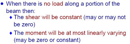
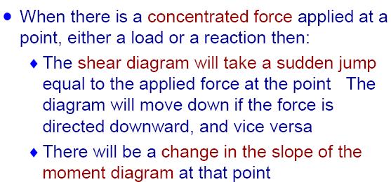
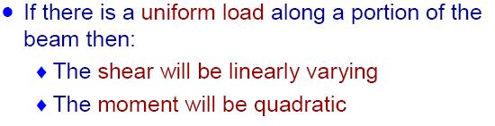
23 If there is no change in the load along the length under consideration, the shear curve is a straight horizontal line (or a curve of zero slope). If a concentrated load exists, then there is a vertical jump in the SFD ( force = drop down on SFD, force = step up on SFD) If a load exists, and is uniformly distributed, the slope of the shear curve is constant and nonhorizontal. If a load exists, and increases in magnitude over successive increments, the slope of the shear curve is positive (approaches the vertical); if the magnitude decreases, the slope of the shear curve is negative (approaches the horizontal). 23
24 If the slope of the SFD is zero, then the moment curve has a constant slope that is equal to the value of the shear for that increment. If the slope of the SFD is positive, then the slope of the moment curve is getting steeper. If the slope of the SFD is negative, then slope of the moment curve is getting flatter. Changes in the shear diagram will produce changes in the shape of the moment curve. The area under the shear curve between two points is equal to the change in bending moment between the same two points. 24
25 The area of the shear diagram to the left or to the right of the section is equal to the moment at that section. The slope of the moment diagram at a given point is the shear at that point. The maximum moment occurs at the point of zero shear. When the shear (also the slope of the moment diagram) is zero, the tangent drawn to the moment diagram is horizontal. 25
26 26
27 27

28 Draw the shear and bending moment diagrams for the beam and loading shown and determine the location and magnitude of the maximum bending moment. 28
29 29
30 30

31 Draw the shear and bending moment diagrams for the beam and loading shown and determine the location and magnitude of the maximum bending moment. 31
32 ENGR 1205 Chapter 10 32
33 33
34 34

35 Draw the shear and bending moment diagrams for the beam and loading shown. 35
Beams. Beams are structural members that offer resistance to bending due to applied load
 Beams Beams are structural members that offer resistance to bending due to applied load 1 Beams Long prismatic members Non-prismatic sections also possible Each cross-section dimension Length of member
dv dx Slope of the shear diagram = - Value of applied loading dm dx Slope of the moment curve = Shear Force
 Beams SFD and BMD Shear and Moment Relationships w dv dx Slope of the shear diagram = - Value of applied loading V dm dx Slope of the moment curve = Shear Force Both equations not applicable at the point
Chapter 7: Internal Forces
 Chapter 7: Internal Forces Chapter Objectives To show how to use the method of sections for determining the internal loadings in a member. To generalize this procedure by formulating equations that can
Determinate portal frame
 eterminate portal frame onsider the frame shown in the figure below with the aim of calculating the bending moment diagram (M), shear force diagram (SF), and axial force diagram (F). P H y R x x R y L
Chapter 7: Bending and Shear in Simple Beams
 Chapter 7: Bending and Shear in Simple Beams Introduction A beam is a long, slender structural member that resists loads that are generally applied transverse (perpendicular) to its longitudinal axis.
MECHANICS OF MATERIALS. Analysis of Beams for Bending
 MECHANICS OF MATERIALS Analysis of Beams for Bending By NUR FARHAYU ARIFFIN Faculty of Civil Engineering & Earth Resources Chapter Description Expected Outcomes Define the elastic deformation of an axially
Types of Structures & Loads
 Structure Analysis I Chapter 4 1 Types of Structures & Loads 1Chapter Chapter 4 Internal lloading Developed in Structural Members Internal loading at a specified Point In General The loading for coplanar
Chapter 7 FORCES IN BEAMS AND CABLES
 hapter 7 FORES IN BEAMS AN ABLES onsider a straight two-force member AB subjected at A and B to equal and opposite forces F and -F directed along AB. utting the member AB at and drawing the free-body B
ENG202 Statics Lecture 16, Section 7.1
 ENG202 Statics Lecture 16, Section 7.1 Internal Forces Developed in Structural Members - Design of any structural member requires an investigation of the loading acting within the member in order to be
Lecture 23 March 12, 2018 Chap 7.3
 Statics - TAM 210 & TAM 211 Lecture 23 March 12, 2018 Chap 7.3 Announcements Upcoming deadlines: Monday (3/12) Mastering Engineering Tutorial 9 Tuesday (3/13) PL HW 8 Quiz 5 (3/14-16) Sign up at CBTF Up
Shear Force and Bending Moment Diagrams
 Shear Force and Bending Moment Diagrams V [ N ] x[m] M [ Nm] x[m] Competencies 1. Draw shear force and bending moment diagrams for point loads and distributed loads 2. Recognize the position of maximum
Outline: Centres of Mass and Centroids. Beams External Effects Beams Internal Effects
 Outline: Centres of Mass and Centroids Centre of Mass Centroids of Lines, Areas and Volumes Composite Bodies Beams External Effects Beams Internal Effects 1 Up to now all forces have been concentrated
Internal Internal Forces Forces
 Internal Forces ENGR 221 March 19, 2003 Lecture Goals Internal Force in Structures Shear Forces Bending Moment Shear and Bending moment Diagrams Internal Forces and Bending The bending moment, M. Moment
BEAM A horizontal or inclined structural member that is designed to resist forces acting to its axis is called a beam
 BEM horizontal or inclined structural member that is designed to resist forces acting to its axis is called a beam INTERNL FORCES IN BEM Whether or not a beam will break, depend on the internal resistances
8.3 Shear and Bending-Moment Diagrams Constructed by Areas
 8.3 Shear and ending-moment Diagrams Constructed by reas 8.3 Shear and ending-moment Diagrams Constructed by reas Procedures and Strategies, page 1 of 3 Procedures and Strategies for Solving Problems Involving
[8] Bending and Shear Loading of Beams
![[8] Bending and Shear Loading of Beams](/thumbs/92/110949676.jpg "[8] Bending and Shear Loading of Beams") [8] Bending and Shear Loading of Beams Page 1 of 28 [8] Bending and Shear Loading of Beams [8.1] Bending of Beams (will not be covered in class) [8.2] Bending Strain and Stress [8.3] Shear in Straight
[8] Bending and Shear Loading of Beams Page 1 of 28 [8] Bending and Shear Loading of Beams [8.1] Bending of Beams (will not be covered in class) [8.2] Bending Strain and Stress [8.3] Shear in Straight
Supplement: Statically Indeterminate Trusses and Frames
 : Statically Indeterminate Trusses and Frames Approximate Analysis - In this supplement, we consider an approximate method of solving statically indeterminate trusses and frames subjected to lateral loads
- Beams are structural member supporting lateral loadings, i.e., these applied perpendicular to the axes.
 4. Shear and Moment functions - Beams are structural member supporting lateral loadings, i.e., these applied perpendicular to the aes. - The design of such members requires a detailed knowledge of the
MECE 3321: Mechanics of Solids Chapter 6
 MECE 3321: Mechanics of Solids Chapter 6 Samantha Ramirez Beams Beams are long straight members that carry loads perpendicular to their longitudinal axis Beams are classified by the way they are supported
ENGINEERING MECHANICS SOLUTIONS UNIT-I
 LONG QUESTIONS ENGINEERING MECHANICS SOLUTIONS UNIT-I 1. A roller shown in Figure 1 is mass 150 Kg. What force P is necessary to start the roller over the block A? =90+25 =115 = 90+25.377 = 115.377 = 360-(115+115.377)
CH. 4 BEAMS & COLUMNS
 CH. 4 BEAMS & COLUMNS BEAMS Beams Basic theory of bending: internal resisting moment at any point in a beam must equal the bending moments produced by the external loads on the beam Rx = Cc + Tt - If the
Chapter 7 INTERNAL FORCES
 Chapter 7 INTERNAL FORCES READING QUIZ 1. In a multiforce member, the member is generally subjected to an internal. A) normal force B) shear force C) bending moment D) All of the above. 2. In mechanics,
ENR202 Mechanics of Materials Lecture 4A Notes and Slides
 Slide 1 Copyright Notice Do not remove this notice. COMMMONWEALTH OF AUSTRALIA Copyright Regulations 1969 WARNING This material has been produced and communicated to you by or on behalf of the University
Bending Stress. Sign convention. Centroid of an area
 Bending Stress Sign convention The positive shear force and bending moments are as shown in the figure. Centroid of an area Figure 40: Sign convention followed. If the area can be divided into n parts
SIGN CONVENTION OF STRESS RESULTANTS
 SIGN CONVENTION OF STRESS RESULTANTS A quick guide to understanding the sign conventions used in the ush Me ull Me models National HE STEM rogramme INTRODUCTION Representing stress resultants graphically
Shear Force V: Positive shear tends to rotate the segment clockwise.
 INTERNL FORCES IN EM efore a structural element can be designed, it is necessary to determine the internal forces that act within the element. The internal forces for a beam section will consist of a shear
Laith Batarseh. internal forces
 Next Previous 1/8/2016 Chapter seven Laith Batarseh Home End Definitions When a member is subjected to external load, an and/or moment are generated inside this member. The value of the generated internal
Chapter 2. Shear Force and Bending Moment. After successfully completing this chapter the students should be able to:
 Chapter Shear Force and Bending Moment This chapter begins with a discussion of beam types. It is also important for students to know and understand the reaction from the types of supports holding the
Stress Analysis Lecture 4 ME 276 Spring Dr./ Ahmed Mohamed Nagib Elmekawy
 Stress Analysis Lecture 4 ME 76 Spring 017-018 Dr./ Ahmed Mohamed Nagib Elmekawy Shear and Moment Diagrams Beam Sign Convention The positive directions are as follows: The internal shear force causes a
MECHANICS OF MATERIALS. Prepared by Engr. John Paul Timola
 MECHANICS OF MATERIALS Prepared by Engr. John Paul Timola Mechanics of materials branch of mechanics that studies the internal effects of stress and strain in a solid body. stress is associated with the
Chapter Objectives. Copyright 2011 Pearson Education South Asia Pte Ltd
 Chapter Objectives To generalize the procedure by formulating equations that can be plotted so that they describe the internal shear and moment throughout a member. To use the relations between distributed
Mechanics of Materials
 Mechanics of Materials 2. Introduction Dr. Rami Zakaria References: 1. Engineering Mechanics: Statics, R.C. Hibbeler, 12 th ed, Pearson 2. Mechanics of Materials: R.C. Hibbeler, 9 th ed, Pearson 3. Mechanics
Stress Engineering Interview Questions Part 1
 Stress Engineering Interview Questions Part 1 Author: Surya Batchu Senior Stress Engineer Founder, STRESS EBOOK LLC. http://www.stressebook.com 1 P a g e Stress Engineering Interview Questions Part 1:
Quizzam Module 1 : Statics
 Structural Steel Design Quizzam odule : Statics NAE Draw shear and moment diagrams for the following loading conditions. Note the reactions. Calculate the maximum amount of internal bending moment. 0 500
Tutorial #1 - CivE. 205 Name: I.D:
 Tutorial # - CivE. 0 Name: I.D: Eercise : For the Beam below: - Calculate the reactions at the supports and check the equilibrium of point a - Define the points at which there is change in load or beam
CHAPTER 8 BENDING MOMENT AND SHEAR FORCE DIAGRAMS
 CHPTE 8 BENDING MOMENT ND SHE FOCE DIGMS EXECISE 5, Page. Determine expressions for the bending moment and shearing force distributions for the following simply supported beam; hence, or otherwise, plot
Module 2. Analysis of Statically Indeterminate Structures by the Matrix Force Method
 Module 2 Analysis of Statically Indeterminate Structures by the Matrix Force Method Lesson 8 The Force Method of Analysis: Beams Instructional Objectives After reading this chapter the student will be
Side Note (Needed for Deflection Calculations): Shear and Moment Diagrams Using Area Method
: Shear and Moment Diagrams Using Area Method") Side Note (Needed for Deflection Calculations): Shear and Moment Diagrams Using Area Method How do we draw the moment and shear diagram for an arbitrarily loaded beam? Is there a easier and faster way
Side Note (Needed for Deflection Calculations): Shear and Moment Diagrams Using Area Method How do we draw the moment and shear diagram for an arbitrarily loaded beam? Is there a easier and faster way
6/6/2008. Qualitative Influence Lines for Statically Indeterminate Structures: Muller-Breslau s Principle
 Qualitative Influence Lines for Statically Indeterminate Structures: Muller-Breslau s Principle The influence line for a force (or moment) response function is given by the deflected shape of the released
OUTCOME 1 - TUTORIAL 3 BENDING MOMENTS. You should judge your progress by completing the self assessment exercises. CONTENTS
 Unit 2: Unit code: QCF Level: 4 Credit value: 15 Engineering Science L/601/1404 OUTCOME 1 - TUTORIAL 3 BENDING MOMENTS 1. Be able to determine the behavioural characteristics of elements of static engineering
Beams III -- Shear Stress: 1
 Beams III -- Shear Stress: 1 Internal Shear Force Shear Stress Formula for Beams The First Area Moment, Q Shear Stresses in Beam Flanges Shear Distribution on an I Beam 1 2 In this stack we will derive
2. Determine the deflection at C of the beam given in fig below. Use principal of virtual work. W L/2 B A L C
 CE-1259, Strength of Materials UNIT I STRESS, STRAIN DEFORMATION OF SOLIDS Part -A 1. Define strain energy density. 2. State Maxwell s reciprocal theorem. 3. Define proof resilience. 4. State Castigliano
Chapter 1 General Introduction Instructor: Dr. Mürüde Çelikağ Office : CE Building Room CE230 and GE241
 CIVL222 STRENGTH OF MATERIALS Chapter 1 General Introduction Instructor: Dr. Mürüde Çelikağ Office : CE Building Room CE230 and GE241 E-mail : murude.celikag@emu.edu.tr 1. INTRODUCTION There are three
Unit II Shear and Bending in Beams
 Unit II Shear and Bending in Beams Syllabus: Beams and Bending- Types of loads, supports - Shear Force and Bending Moment Diagrams for statically determinate beam with concentrated load, UDL, uniformly
8-5 Conjugate-Beam method. 8-5 Conjugate-Beam method. 8-5 Conjugate-Beam method. 8-5 Conjugate-Beam method
 The basis for the method comes from the similarity of eqn.1 &. to eqn 8. & 8. To show this similarity, we can write these eqn as shown dv dx w d θ M dx d M w dx d v M dx Here the shear V compares with
Chapter Objectives. Copyright 2011 Pearson Education South Asia Pte Ltd
 Chapter Objectives To develop the equations of equilibrium for a rigid body. To introduce the concept of the free-body diagram for a rigid body. To show how to solve rigid-body equilibrium problems using
Check Homework. Reading Quiz Applications Equations of Equilibrium Example Problems Concept Questions Group Problem Solving Attention Quiz
 THREE-DIMENSIONAL FORCE SYSTEMS Today s Objectives: Students will be able to solve 3-D particle equilibrium problems by a) Drawing a 3-D free body diagram, and, b) Applying the three scalar equations (based
Module 3. Analysis of Statically Indeterminate Structures by the Displacement Method
 odule 3 Analysis of Statically Indeterminate Structures by the Displacement ethod Lesson 16 The Slope-Deflection ethod: rames Without Sidesway Instructional Objectives After reading this chapter the student
Strength of Materials Prof. S.K.Bhattacharya Dept. of Civil Engineering, I.I.T., Kharagpur Lecture No.26 Stresses in Beams-I
 Strength of Materials Prof. S.K.Bhattacharya Dept. of Civil Engineering, I.I.T., Kharagpur Lecture No.26 Stresses in Beams-I Welcome to the first lesson of the 6th module which is on Stresses in Beams
Chapter 2: Deflections of Structures
 Chapter 2: Deflections of Structures Fig. 4.1. (Fig. 2.1.) ASTU, Dept. of C Eng., Prepared by: Melkamu E. Page 1 (2.1) (4.1) (2.2) Fig.4.2 Fig.2.2 ASTU, Dept. of C Eng., Prepared by: Melkamu E. Page 2
SAB2223 Mechanics of Materials and Structures
 S2223 Mechanics of Materials and Structures TOPIC 2 SHER FORCE ND ENDING MOMENT Lecturer: Dr. Shek Poi Ngian TOPIC 2 SHER FORCE ND ENDING MOMENT Shear Force and ending Moment Introduction Types of beams
Chapter 3. Load and Stress Analysis
 Chapter 3 Load and Stress Analysis 2 Shear Force and Bending Moments in Beams Internal shear force V & bending moment M must ensure equilibrium Fig. 3 2 Sign Conventions for Bending and Shear Fig. 3 3
6. Bending CHAPTER OBJECTIVES
 CHAPTER OBJECTIVES Determine stress in members caused by bending Discuss how to establish shear and moment diagrams for a beam or shaft Determine largest shear and moment in a member, and specify where
Supplement: Statically Indeterminate Frames
 : Statically Indeterminate Frames Approximate Analysis - In this supplement, we consider another approximate method of solving statically indeterminate frames subjected to lateral loads known as the. Like
UNIT- I Thin plate theory, Structural Instability:
 UNIT- I Thin plate theory, Structural Instability: Analysis of thin rectangular plates subject to bending, twisting, distributed transverse load, combined bending and in-plane loading Thin plates having
INTERNAL FORCES Today s Objective: Students will be able to: 1. Use the method of sections for determining internal forces in 2-D load cases.
 INTERNAL FORCES Today s Objective: Students will be able to: 1. Use the method of sections for determining internal forces in 2-D load cases. In-Class Activities: Check Homework, if any Reading Quiz Applications
CIVIL DEPARTMENT MECHANICS OF STRUCTURES- ASSIGNMENT NO 1. Brach: CE YEAR:
 MECHANICS OF STRUCTURES- ASSIGNMENT NO 1 SEMESTER: V 1) Find the least moment of Inertia about the centroidal axes X-X and Y-Y of an unequal angle section 125 mm 75 mm 10 mm as shown in figure 2) Determine
both an analytical approach and the pole method, determine: (a) the direction of the
 the direction of the") Quantitative Problems Problem 4-3 Figure 4-45 shows the state of stress at a point within a soil deposit. Using both an analytical approach and the pole method, determine: (a) the direction of the principal
Quantitative Problems Problem 4-3 Figure 4-45 shows the state of stress at a point within a soil deposit. Using both an analytical approach and the pole method, determine: (a) the direction of the principal
MTE 119 STATICS FINAL HELP SESSION REVIEW PROBLEMS PAGE 1 9 NAME & ID DATE. Example Problem P.1
 MTE STATICS Example Problem P. Beer & Johnston, 004 by Mc Graw-Hill Companies, Inc. The structure shown consists of a beam of rectangular cross section (4in width, 8in height. (a Draw the shear and bending
 techie-touch.blogspot.com DEPARTMENT OF CIVIL ENGINEERING ANNA UNIVERSITY QUESTION BANK CE 2302 STRUCTURAL ANALYSIS-I TWO MARK QUESTIONS UNIT I DEFLECTION OF DETERMINATE STRUCTURES 1. Write any two important
7 TRANSVERSE SHEAR transverse shear stress longitudinal shear stresses
 7 TRANSVERSE SHEAR Before we develop a relationship that describes the shear-stress distribution over the cross section of a beam, we will make some preliminary remarks regarding the way shear acts within
EQUATIONS OF EQUILIBRIUM & TWO- AND THREE-FORCE MEMEBERS
 EQUATIONS OF EQUILIBRIUM & TWO- AND THREE-FORCE MEMEBERS Today s Objectives: Students will be able to: a) Apply equations of equilibrium to solve for unknowns, and b) Recognize two-force members. In-Class
Chapter 4.1: Shear and Moment Diagram
 Chapter 4.1: Shear and Moment Diagram Chapter 5: Stresses in Beams Chapter 6: Classical Methods Beam Types Generally, beams are classified according to how the beam is supported and according to crosssection
Mechanics of Materials CIVL 3322 / MECH 3322
 Mechanics of Materials CIVL 3322 / MECH 3322 2 3 4 5 6 7 8 9 10 A Quiz 11 A Quiz 12 A Quiz 13 A Quiz 14 A Quiz 15 A Quiz 16 In Statics, we spent most of our time looking at reactions at supports Two variations
University of Pretoria Department of Mechanical & Aeronautical Engineering MOW 227, 2 nd Semester 2014
 Universit of Pretoria Department of Mechanical & Aeronautical Engineering MOW 7, nd Semester 04 Semester Test Date: August, 04 Total: 00 Internal eaminer: Duration: hours Mr. Riaan Meeser Instructions:
SSC-JE MAINS ONLINE TEST SERIES / CIVIL ENGINEERING SOM + TOS
 SSC-JE MAINS ONLINE TEST SERIES / CIVIL ENGINEERING SOM + TOS Time Allowed:2 Hours Maximum Marks: 300 Attention: 1. Paper consists of Part A (Civil & Structural) Part B (Electrical) and Part C (Mechanical)
MECHANICS OF MATERIALS
 MM 210 MECHANICS OF MATERIALS 2012-2013 1 1.INTRODUCTION TO MECHANICS OF MATERIALS WHAT IS MECHANICS OF MATERIALS? Mechanics is the physical science that deals with the conditions of rest or motion of
Engineering Mechanics: Statics in SI Units, 12e
 Engineering Mechanics: Statics in SI Units, 12e 5 Equilibrium of a Rigid Body Chapter Objectives Develop the equations of equilibrium for a rigid body Concept of the free-body diagram for a rigid body
Final Examination Study Set 1. (Solutions will be in the Solutions Manual of Textbook)
") Final Examination Study Set 1 (Solutions will be in the Solutions Manual of Textbook) Final Examination Study Set 2 (Solutions will be in the Solutions Manual of Textbook) 3/86 The shaft, lever,
Final Examination Study Set 1 (Solutions will be in the Solutions Manual of Textbook) Final Examination Study Set 2 (Solutions will be in the Solutions Manual of Textbook) 3/86 The shaft, lever,
Unit Workbook 1 Level 4 ENG U8 Mechanical Principles 2018 UniCourse Ltd. All Rights Reserved. Sample
 Pearson BTEC Levels 4 Higher Nationals in Engineering (RQF) Unit 8: Mechanical Principles Unit Workbook 1 in a series of 4 for this unit Learning Outcome 1 Static Mechanical Systems Page 1 of 23 1.1 Shafts
ENGR-1100 Introduction to Engineering Analysis. Lecture 13
 ENGR-1100 Introduction to Engineering Analysis Lecture 13 EQUILIBRIUM OF A RIGID BODY & FREE-BODY DIAGRAMS Today s Objectives: Students will be able to: a) Identify support reactions, and, b) Draw a free-body
CIV100 Mechanics. Module 5: Internal Forces and Design. by: Jinyue Zhang. By the end of this Module you should be able to:
 CIV100 Mechanics Module 5: Internal Forces and Design by: Jinyue Zhang Module Objective By the end of this Module you should be able to: Find internal forces of any structural members Understand how Shear
REVIEW. Final Exam. Final Exam Information. Final Exam Information. Strategy for Studying. Test taking strategy. Sign Convention Rules
 Final Exam Information REVIEW Final Exam (Print notes) DATE: WEDNESDAY, MAY 12 TIME: 1:30 PM - 3:30 PM ROOM ASSIGNMENT: Toomey Hall Room 199 1 2 Final Exam Information Comprehensive exam covers all topics
BOOK OF COURSE WORKS ON STRENGTH OF MATERIALS FOR THE 2 ND YEAR STUDENTS OF THE UACEG
 BOOK OF COURSE WORKS ON STRENGTH OF MATERIALS FOR THE ND YEAR STUDENTS OF THE UACEG Assoc.Prof. Dr. Svetlana Lilkova-Markova, Chief. Assist. Prof. Dimitar Lolov Sofia, 011 STRENGTH OF MATERIALS GENERAL
Chapter 4 Deflection and Stiffness
 Chapter 4 Deflection and Stiffness Asst. Prof. Dr. Supakit Rooppakhun Chapter Outline Deflection and Stiffness 4-1 Spring Rates 4-2 Tension, Compression, and Torsion 4-3 Deflection Due to Bending 4-4 Beam
STRUCTURAL ANALYSIS BFC Statically Indeterminate Beam & Frame
 STRUCTURA ANAYSIS BFC 21403 Statically Indeterminate Beam & Frame Introduction Analysis for indeterminate structure of beam and frame: 1. Slope-deflection method 2. Moment distribution method Displacement
EDEXCEL NATIONAL CERTIFICATE/DIPLOMA FURTHER MECHANICAL PRINCIPLES AND APPLICATIONS UNIT 11 - NQF LEVEL 3 OUTCOME 1 - FRAMES AND BEAMS
 EDEXCEL NATIONAL CERTIFICATE/DIPLOMA FURTHER MECHANICAL PRINCIPLES AND APPLICATIONS UNIT 11 - NQF LEVEL 3 OUTCOME 1 - FRAMES AND BEAMS TUTORIAL 2 - BEAMS CONTENT Be able to determine the forces acting
PURE BENDING. If a simply supported beam carries two point loads of 10 kn as shown in the following figure, pure bending occurs at segment BC.
 BENDING STRESS The effect of a bending moment applied to a cross-section of a beam is to induce a state of stress across that section. These stresses are known as bending stresses and they act normally
P.E. Civil Exam Review:
 P.E. Civil Exam Review: Structural Analysis J.P. Mohsen Email: jpm@louisville.edu Structures Determinate Indeterminate STATICALLY DETERMINATE STATICALLY INDETERMINATE Stability and Determinacy of Trusses
Lab Exercise #5: Tension and Bending with Strain Gages
 Lab Exercise #5: Tension and Bending with Strain Gages Pre-lab assignment: Yes No Goals: 1. To evaluate tension and bending stress models and Hooke s Law. a. σ = Mc/I and σ = P/A 2. To determine material
CH. 5 TRUSSES BASIC PRINCIPLES TRUSS ANALYSIS. Typical depth-to-span ratios range from 1:10 to 1:20. First: determine loads in various members
 CH. 5 TRUSSES BASIC PRINCIPLES Typical depth-to-span ratios range from 1:10 to 1:20 - Flat trusses require less overall depth than pitched trusses Spans: 40-200 Spacing: 10 to 40 on center - Residential
OUT ON A LIMB AND HUNG OUT TO DRY :
 27-Nov-12 17:03 1 of 2 h p://edugen.wileyplus.com/edugen/courses/crs1404/pc/c10/c2hlchbhcmq3mjewyzewxzeuegzvcm0.enc?course=crs1404&id=ref CHAPTER 10 OUT ON A LIMB AND HUNG OUT TO DRY : A LOOK AT INTERNAL
Shear force and bending moment of beams 2.1 Beams 2.2 Classification of beams 1. Cantilever Beam Built-in encastre' Cantilever
 CHAPTER TWO Shear force and bending moment of beams 2.1 Beams A beam is a structural member resting on supports to carry vertical loads. Beams are generally placed horizontally; the amount and extent of
Strength of Materials II (Mechanics of Materials) (SI Units) Dr. Ashraf Alfeehan
 (SI Units) Dr. Ashraf Alfeehan") Strength of Materials II (Mechanics of Materials) (SI Units) Dr. Ashraf Alfeehan 2017-2018 Mechanics of Material II Text Books Mechanics of Materials, 10th edition (SI version), by: R. C. Hibbeler, 2017
Strength of Materials II (Mechanics of Materials) (SI Units) Dr. Ashraf Alfeehan 2017-2018 Mechanics of Material II Text Books Mechanics of Materials, 10th edition (SI version), by: R. C. Hibbeler, 2017
Ishik University / Sulaimani Architecture Department. Structure. ARCH 214 Chapter -5- Equilibrium of a Rigid Body
 Ishik University / Sulaimani Architecture Department 1 Structure ARCH 214 Chapter -5- Equilibrium of a Rigid Body CHAPTER OBJECTIVES To develop the equations of equilibrium for a rigid body. To introduce
FIXED BEAMS IN BENDING
 FIXED BEAMS IN BENDING INTRODUCTION Fixed or built-in beams are commonly used in building construction because they possess high rigidity in comparison to simply supported beams. When a simply supported
SN QUESTION YEAR MARK 1. State and prove the relationship between shearing stress and rate of change of bending moment at a section in a loaded beam.
 ALPHA COLLEGE OF ENGINEERING AND TECHNOLOGY DEPARTMENT OF MECHANICAL ENGINEERING MECHANICS OF SOLIDS (21000) ASSIGNMENT 1 SIMPLE STRESSES AND STRAINS SN QUESTION YEAR MARK 1 State and prove the relationship
UNIT IV FLEXIBILTY AND STIFFNESS METHOD
 SIDDHARTH GROUP OF INSTITUTIONS :: PUTTUR Siddharth Nagar, Narayanavanam Road 517583 QUESTION BANK (DESCRIPTIVE) Subject with Code : SA-II (13A01505) Year & Sem: III-B.Tech & I-Sem Course & Branch: B.Tech
Engineering Mechanics Department of Mechanical Engineering Dr. G. Saravana Kumar Indian Institute of Technology, Guwahati
 Engineering Mechanics Department of Mechanical Engineering Dr. G. Saravana Kumar Indian Institute of Technology, Guwahati Module 3 Lecture 6 Internal Forces Today, we will see analysis of structures part
SAULT COLLEGE OF APPLIED ARTS & TECHNOLOGY SAULT STE. MARIE, ONTARIO COURSE OUTLINE STRENGTH OF MATERIALS MECHANICAL TECHNOLOGY
 (/.- SAULT COLLEGE OF APPLIED ARTS & TECHNOLOGY SAULT STE. MARIE, ONTARIO COURSE OUTLINE Course Title: Code No.: Program: Semester: Date: Author: STRENGTH OF MATERIALS MCH 202 MECHANICAL TECHNOLOGY THREE
Assumptions: beam is initially straight, is elastically deformed by the loads, such that the slope and deflection of the elastic curve are
 *12.4 SLOPE & DISPLACEMENT BY THE MOMENT-AREA METHOD Assumptions: beam is initially straight, is elastically deformed by the loads, such that the slope and deflection of the elastic curve are very small,
UNIT II SLOPE DEFLECION AND MOMENT DISTRIBUTION METHOD
 SIDDHARTH GROUP OF INSTITUTIONS :: PUTTUR Siddharth Nagar, Narayanavanam Road 517583 QUESTION BANK (DESCRIPTIVE) Subject with Code : SA-II (13A01505) Year & Sem: III-B.Tech & I-Sem Course & Branch: B.Tech
Equilibrium of a Particle
 ME 108 - Statics Equilibrium of a Particle Chapter 3 Applications For a spool of given weight, what are the forces in cables AB and AC? Applications For a given weight of the lights, what are the forces
Example: 5-panel parallel-chord truss. 8 ft. 5 k 5 k 5 k 5 k. F yield = 36 ksi F tension = 21 ksi F comp. = 10 ksi. 6 ft.
 CE 331, Spring 2004 Beam Analogy for Designing Trusses 1 / 9 We need to make several decisions in designing trusses. First, we need to choose a truss. Then we need to determine the height of the truss
ENGINEERING COUNCIL DIPLOMA LEVEL MECHANICS OF SOLIDS D209 TUTORIAL 3 - SHEAR FORCE AND BENDING MOMENTS IN BEAMS
 ENGINEERING COUNCIL DIPLOMA LEVEL MECHANICS OF SOLIDS D209 TUTORIAL 3 - SHEAR FORCE AND BENDING MOMENTS IN BEAMS You should judge your progress by completing the self assessment exercises. On completion
R13. II B. Tech I Semester Regular Examinations, Jan MECHANICS OF SOLIDS (Com. to ME, AME, AE, MTE) PART-A
 PART-A") SET - 1 II B. Tech I Semester Regular Examinations, Jan - 2015 MECHANICS OF SOLIDS (Com. to ME, AME, AE, MTE) Time: 3 hours Max. Marks: 70 Note: 1. Question Paper consists of two parts (Part-A and Part-B)
SET - 1 II B. Tech I Semester Regular Examinations, Jan - 2015 MECHANICS OF SOLIDS (Com. to ME, AME, AE, MTE) Time: 3 hours Max. Marks: 70 Note: 1. Question Paper consists of two parts (Part-A and Part-B)
Shear Force and Bending Moment Diagrams for a Beam Steven Vukazich San Jose State University
 Shear Force and Bending oment Diagrams for a Beam Steven ukazich San Jose State University General procedure for the construction of internal force diagrams 1. Find all of the eternal forces and draw the
Engineering Mechanics Statics
 Mechanical Systems Engineering _ 2016 Engineering Mechanics Statics 7. Equilibrium of a Rigid Body Dr. Rami Zakaria Conditions for Rigid-Body Equilibrium Forces on a particle Forces on a rigid body The
STRENGTH OF MATERIALS-I. Unit-1. Simple stresses and strains
 STRENGTH OF MATERIALS-I Unit-1 Simple stresses and strains 1. What is the Principle of surveying 2. Define Magnetic, True & Arbitrary Meridians. 3. Mention different types of chains 4. Differentiate between
The case where there is no net effect of the forces acting on a rigid body
 The case where there is no net effect of the forces acting on a rigid body Outline: Introduction and Definition of Equilibrium Equilibrium in Two-Dimensions Special cases Equilibrium in Three-Dimensions