Chapter 11. Displacement Method of Analysis Slope Deflection Method
|
|
|
- Giles Holmes
- 5 years ago
- Views:
Transcription
1 Chapter 11 Displacement ethod of Analysis Slope Deflection ethod
2 Displacement ethod of Analysis Two main methods of analyzing indeterminate structure Force method The method of consistent deformations & the equation of three moment The primary unknowns are forces or moments Displacement method The slope-deflection method & the moment distribution method The primary unknown is displacements (rotation & deflection) It is particularly useful for the analysis of highly statically indeterminate structures Easily programmed on a computer & used to analyze a wide range of indeterminate structures
3 Displacement ethod of Analysis Degree of Freedom The number of possible joint rotations & independent joint translations in a structure is called the degree of freedom of the structure In three dimensions each node on a frame can have at most three linear displacements & three rotational displacements. In two dimension each node can have at most two linear displacements & one rotational displacement. DOF = n J R - n number of possible joint s movements - J number of joints - R number of restrained movements
4 Displacement ethod of Analysis Degree of Freedom DOF = n J R - n number of possible joint s movements - n = 2 for two dimensional truss structures - n = 3 for three dimensional truss structures - n= 3 for two dimensional frame structures - n= 6 for three dimensional frame structures - J number of joints - R number of restrained movements Neglecting Axial deformation DOF = n J R m - m number of members
5 Displacement ethod of Analysis
6 Slope-Deflection Equations Derivation
7 Slope-Deflection Equations Angular Displacement at A, A 1 AB L 1 2L A' 0 L L 0 2 EI 3 2 EI 3 1 L 1 AB 2L B ' 0 L L AL 0 2 EI 3 2 EI 3 4EI 2EI A & B A A L L AB
8 Slope-Deflection Equations Angular Displacement at B, B AB 4EI B L 2EI B L
9 Slope-Deflection Equations Relative Linear Displacement B ' L L L L 2 EI 3 2 EI EI AB 2 L
10 Slope-Deflection Equations Fixed-End oment Fy 0. 1 PL 1 L 2 L 0. 2 EI 2 EI Fixed-End moment FE PL 8
 (")
11 Slope-Deflection Equations AB ( FE ) ( FE ) AB

12 Slope-Deflection Equations Fixed-End oment
13 Slope-Deflection Equations Slope-deflection equations The resultant moment (adding all equations together) 2 I E 2 3 ( FE ) L L AB A B AB 2 I E 2 3 ( FE ) L L B A Lets represent the member stiffness as k = I/L & The span ration due to displacement as = /L Referring to one end of the span as near end (N) & the other end as the far end (F). Rewrite the equations 2EK 2 3 ( FE ) N N F N 2EK 2 3 ( FE ) F F N F
' N N F N 0 2EK 2 3 0 F N ultiply the first equation by 2 and subtracting the second equation from it 3 EK ( FE )' N N")
14 Slope-Deflection Equations Slope-deflection equations for pin supported End Span If the far end is a pin or a roller support 2EK 2 3 ( FE )' N N F N 0 2EK F N ultiply the first equation by 2 and subtracting the second equation from it 3 EK ( FE )' N N N
15 Fixed End oment Table
16 Fixed End oment Table
17 Fixed End oment Table- Continue
 F F N F 3 EK ( FE )' N N")
18 Summary 2EK 2 3 ( FE ) N N F N 2EK 2 3 ( FE ) F F N F 3 EK ( FE )' N N N
19 Slope-Deflection Equations N, F = the internal moment in the near & far end of the span. Considered positive when acting in a clockwise direction E, k = modulus of elasticity of material & span stiffness k = I/L N, F = near & far end slope of the span at the supports in radians. Considered positive when acting in a clockwise direction = span ration due to a linear displacement / L. If the right end of a member sinks with respect the the left end the sign is positive
20 Slope-Deflection Equations Steps to analyzing beams using this method Find the fixed end moments of each span (both ends left & right) Apply the slope deflection equation on each span & identify the unknowns Write down the joint equilibrium equations Solve the equilibrium equations to get the unknown rotation & deflections Determine the end moments and then treat each span as simply supported beam subjected to given load & end moments so you can workout the reactions & draw the bending moment & shear force diagram
21 Example 1 Draw the bending moment & shear force diagram. Fixed End oment 4 4 FE AB 2 t. m FE 2 t. m FE 6 t. m FE CB 6 t. m 12 4t 4m 2t/m A I B 2I C 6m Slope Deflection Equations I A 0 AB 2E 2 A B 0 2 AB 0.5EIB 2 4 I A 0 2E A 2 B 0 2 EIB 2 4 2I 0 4 C 2E 2 B C 0 6 EIB I 0 2 C CB 2E B 2 C 0 6 CB EIB 6 6 3
22 Joint Equilibrium Equations Joint B EIB 2 EIB 6 0. B 3 EI Substituting in slope deflection equations 1.7 AB 0.5EI t. m EI 1.7 EI t. m EI 3.7 t. m CB EI t. m 3 EI 1.15 Computing The Reactions 4t 3.7 R R A B t t R A R B1
23 R R B 2 C t t 3.7 2t/m R B2 R C
24 Determine the internal moments in the beam at the supports. Fixed End oment FE FE FE AB kn. m kn. m kn. m 8 Slope Deflection Equations Example 2 60kN I 1 E EI 6 3 I 2 E EI 6 3 I 1 3E B EIB A 0 AB 2 2 A B AB B A 0 2 A 2 B B m 6m 30kN/m A B C I I 6m
25 Joint Equilibrium Equations Joint B EIB EIB EIB EI 70 B Substituting in slope deflection equations AB 1 (70) kn. m 3 2 (70) kn. m 3 1 (70) kn. m 2
26 Example 3 Example 2: Determine the internal moments in the beam at the supports Support A; downward movement of 0.3cm & clockwise rotation of rad. Support B; downward movement of 1.2cm. Support C downward movement of 0.6cm. EI = 5000 t.m 2 Fixed End oment FE AB FE FE FE CB Displacements: A AB Slope Deflection Equations AB B B A B C I 6m I 6m
27 35000 B 6 Joint Equilibrium Equations Joint B B B rad 0.001
28 Substituting in slope deflection equations AB t. m t. m t. m 6

29 Example 1b FE AB FE 0.0 A C 0.0
30 Slope Deflection Equations
31 Equilibrium Equations
32 Example 2b
33
34
35 Example 3b
36
37 Example 4
38
39
40 Analysis of Frames Without Sway The side movement of the end of a column in a frame is called SWAY.

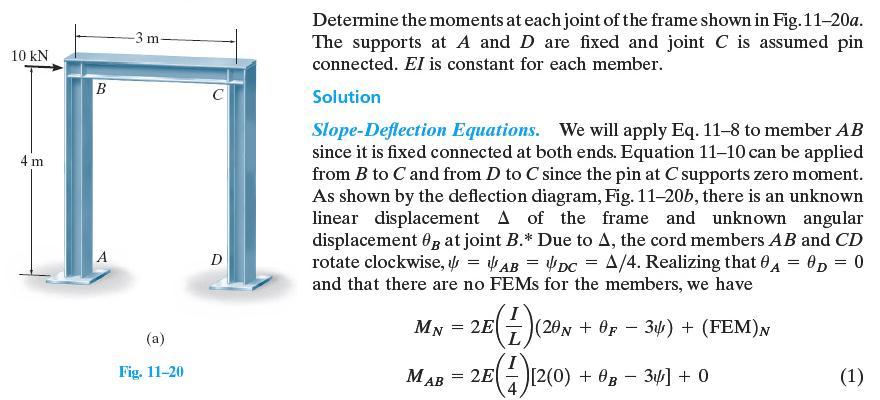
41 Example 5 Determine the moment at each joint of the frame. EI is constant Fixed End oment FE FE 0. AB FE FE FE CB CD kn. m kn. m 96 FE 0. DC Slope Deflection Equations I AB 2E 0. B AB I 2E 2 B A = EI A = EI B B
42 I 2E 2B C I CB 2E 2C B I CD 2E 2 C I DC 2E 0 C Joint Equilibrium Equations Joint B 0 CB CD EI 0.5EI 0.25EI C C B D = 0. D = EI 0.25EI 80 B C 0.5EI 0.25EI 80 CB C B CD DC 0.333EI C EI 0.333EI B 0.5EI B 0.25EI C EI B 0.25EI C 80 Joint C C 0.833EI 0.25EI 80 C B
43 Two equation & two unknown B Substituting in slope deflection equations AB CB CD DC C EI 22.9 kn. m 45.7 kn. m 45.7 kn. m 45.7 kn. m 45.7 kn. m 22.9 kn. m
44 Example 6
45
46
47
48 Example 6b Draw the bending moment diagram Fixed End oment FE FE FE AB FE CB kn. m kn. m kn. m kn. m FE BE FE EB FE CF FE FC 0 A 1m 20kN I 3m B I E 48kN/m 2I 3m 4m C 2I F 4m 2m 30kN I D CD kn. m Slope Deflection Equations I AB 2E 2A B A = 0. AB 2 EIB
49 I 2E A 2B A = 0. 4 EIB I 2E 2B C I CB 2E B 2C EI EI 64 B C EI 2EI 64 CB B C I BE 2E 2B E I EB 2E 2E B E = 0. E = 0. BE EB 4 EIB 3 2 EIB 3 2I CF 2E 2C F I FC 2E 2F C F = 0. F = 0. CF FC 2EI EI C C
50 Equilibrium Equations Joint B BE EIB EIB EIC 64 EIB Joint C CB CF CD EI 2EI 64 2EI B C C EI B 4.67EI EI EI 4 C B C Two equation & two unknown EI B EI C 4.18 Substituting in slope deflection equations AB kn. m kn. m knm 3 CB ( 4.18) kn. m
51 BE EB kn. m kn. m EI ( 4.18) 8.35 kn. m CF FC 4.18 kn. m
52 Slope Deflection (Frame with Sway) Analysis of Frames with Sway

53 Example 7 Draw the bending moment diagram. EI constant Fixed End oment As there is no span loading in any of the member FE for all the members is zero Slope Deflection Equations I AB 2E 0. B EIB EI 6 24 I 2E 2 B EIB EI 3 24
54 I E 2 B C 3 0 EIB EIC I CB E 2 C B 0 0 EIB EIC I CD E 2C EIC EI I DC E 0 C 3 0 EIC EI Equilibrium Equations Joint B B = EIB EI EIB EIC EI 14.4EI 3.2EI 0 1 Joint C C = 0 CB CD 0 B C
55 EIB EIC EIC EI EI 7.2EI B 26.4EI C 0 2 Three unknown & just two equations so we need another equilibrium equation. Let take F x = H H 0. H H A D A D CD AB DC AB CD DC EIB EI EI B EI EIC EI EIC EI EI 0.75EI 0.333EI B C
56 Now solve the three equation EI EIB EI C 720 EIC EIB EI Substituting in slope deflection equations AB CB CD DC 208 kn. m 135 kn. m 135 kn. m 95 kn. m 95 kn. m 110 kn. m
57
58 Example 7 Draw the bending moment diagram. EI constant Fixed End oment FE FE FE FE AB CB CD FE kn. m kn. m 12 FE 0. DC Slope Deflection Equations I AB 2E 0. B EIB EI 6 24
59 I 2E 2 B EIB EI 3 24 I E 2B C EIB EIC I 2 4 CB 2E 2C B EIB EIC I 2 1 CD 2E 2 C EIC EI 9 54 I 1 1 DC 2E 0 C EIC EI 9 54 Equilibrium Equations Joint B B = EIB EI EIB EIC EI 14.4EI 3.2EI B C
60 Joint C C = 0 CB CD EIB EIC 375 EIC EI EI 7.2EI 26.4EI Three unknown & just two equations so we need another equilibrium equation. Let take F x = H H 0. A D AB H A 12 CD DC H D AB CD DC B EIB EI EI B EI EIC EI EIC EI EI 0.75EI 0.333EI B C C
61 Now solve the three equation EI R1-R2 EIB EI R1-R3 C EI R2-R3 EIB EI C EI EIB EI C 4257 Substituting in slope deflection equations AB kn. m kn. m EIC EIB EI
62 - CB ( 804.7) kn. m ( 804.7) kn. m CD DC 2 1 ( 804.7) kn. m ( 804.7) kn. m
63 Example 8
64
65
66

67 Draw the bending moment diagram. EI constant Fixed End oment Example 9 As there is no span loading in any of the member FE for all the members is zero Slope Deflection Equations I AB E EIB EI B 3 0 I E EIB EI B 0 3 0
68 I 0 BE 2E 2B E I 0 EB 2E 2E B I 1 FE 2E 0. E I 1 EF 2E 2 E I E 5 5 I 2 CB 2E 2C B B C EIB EIE EIB EIE EIE EI EIE EI EIB EIC EI EIB EIC EI I 0 CD 2E 2C D I 0 DC 2E 2D C EIC EID EIC EID 7 7
69 I E 5 5 I 2 ED 2E 2E D DE 2 2 D E EID EIE EI EID EIE EI Equilibrium Equations Joint B B = 0 BE EIB EI 1 EIB EIC EI 2 EIB EIE EI 70EI 50EI 42EI 42EI 0 1 Joint E E = 0 B C E 1 2 EB ED EF EIB EIE EID EIE EI 2 EIE EI EI 70EI 380EI 42EI 42EI 0 2 B D E
70 Joint C C = 0 CB CD EIB EIC EI 2 EIC EID EI 240EI 50EI 42EI 0 3 B C D 2 Joint D D = 0 DC DE EIC EID EID EIE EI EI 240EI 70EI 42EI 0 4 C D E Top story F X = 0 40 H H 0 H H B E B E CB DE 5 5 ED 2 H B H E
71 EIB EIC EI 2 EIB EIC EI EID EIE EI 2 EID EIE EI EI 6EI 6EI 6EI 4.8EI 1000 B C D E 2 5 Bottom story F X = H H 0 A F AB H A 5 EF FE H F EIB EI 1 EIB EI EIE EI 1 EIE EI EI 30EI 24EI B E 1 H A H F
72 6 unknown and 6 equation EIB EI 0 C EID EIE EI EI Substituting in slope deflection equations AB kn. m kn. m BE EB kn. m kn. m FE EF EIB EIC EI D EIE EI EI kn. m kn. m 31.6 kn. m CD 68.4 kn. m DE 68.4 kn. m CB 68.4 kn. m DC 68.4 kn. m ED 31.6 kn. m
73

74 Example 10 Draw the bending moment diagram. EI constant Degree of freedom DOF = 3x4-6-3 = 3 That means we got three unknown & we need three equations Before we start let us discus the relative displacement () of each span
75 The relative displacement () for span AB is equal AB 0. = AB (clockwise) B CD C The relative displacement () for span is equal 0. = (counterclockwise) The relative displacement () for span CD is equal 0. ( CD )= CD (clockwise) A 60 o AB Let us build a relationship between AB, & CD take AB = = AB sin30 = 0.5 CD = AB cos30 = So in the slope deflection equations we will use; as the relative displacement of span AB. 0.5 as the relative displacement of span as the relative displacement of span CD. B 60 o 60 o CD AB =30 o D
76 Fixed End oment FE FE AB FE CB FE CD FE m FE DC t. m 0. Slope Deflection Equations I AB 2E 0. B I 2E 2 B I 0.5 2E 2B C I 0.5 CB 2E B 2C EIB EI EIB EI EIB EIC EI EIB EIC EI
77 I CD 2E 2 C I DC 2E 0 C EIC EI EIC EI 3 6 Equilibrium Equations Joint B B = EIB EI EIB EIC EI EI B 24EI C 23EI Joint C C = 0 CB CD EIB EIC EI EIC EI EI B 80EI C 2.072EI 128 2
78 Third Equilibrium Equations (ethod 1) AB AB DC DC CD t 6.92m AB CD DC EI 3.1EI EI B C m 6.0
79 2.6m Third Equilibrium Equations (ethod 2) Third equation F X = 0 H H 0 A D From the free body diagram for column CD H D CD 6 DC B C CD Free body diagram for column AB H 2.6 V A AB A H A A 1.5m AB Free body diagram for Beam V V B CB A V A CB V 4 B AB CB H A AB CB CD DC V B B 2t/m DC D C H D CB
80 AB CB CD DC EIB EI EIB EI 9 EIB EIC EI EIB EIC EI EIC EI EIC EI EI 3.1EI EI B C Solving the three equation EIB EIC EI 144 EIB EIC EI 6.77
81 Solving the three equation EIB EIC EI 144 EIB EIC EI 6.77
82 Substituting in slope deflection equations AB 2.44 t. m 0.36 t. m 2.78 CB 0.36 t. m 2.78 t. m B _ C _ 2.78 CD DC 2.78 t. m 1.88 t. m 2.44 A D
83 Example Draw the bending moment diagram. EI constant Before we start let us discus the relative displacement () of each span
84 The relative displacement () for span AB is equal AB 0. = AB (clockwise) The relative displacement () for span is equal ( 2 ) 1 = ( ) = (counterclockwise) The relative displacement () for span CD is equal 0. ( CD )= CD (clockwise) A = B C 2 1 AB CD D Let us build a relationship between AB, & CD take AB = = 2( AB cos) = 2 5/8.6 = CD = AB = So in the slope deflection equations we will use; as the relative displacement of span AB as the relative displacement of span. as the relative displacement of span CD. B AB CD = 2 & CD = AB because of the symmetry in the geometry
85 Fixed End oment FE FE AB FE CB FE CD FE kn. m FE DC kn. m 0. Slope Deflection Equations I AB 2E 0. B I 2E 2 B I E 2B C I CB 2E 2C B EIB EI EIB EI EIB EIC EI EIB EIC EI
86 I CD 2E 2 C I DC 2E 0 C EIC EI EIC EI Equilibrium Equations Joint B B = EIB EI EIB EIC EI EI 28.57EI 6.13EI CB B Joint C C = 0 CD 0 C EIB EIC EI EIC EI EI EI 6.13EI B C
87 7m 7m Third equation F X = 0 6 H H 0 A D Free body diagram for column AB H 7 V 5 0 A AB A Free body diagram for Beam V B CB H A AB CB V A V B 14 7 AB 5 CB H A From the free body diagram for column CD H 7 V 5 0 D CD DC D V V C CB D CB VC 14 7 A V A 5m V B B B 4kN/m C V C C CB CD DC D 5m H V D D
88 5 CD DC CB H D H H 0 A D AB CB CD DC CB AB CD DC CB EIB EI EIB EI 7 EIC EI EIC EI 10 EIB EIC EI EIB EIC EI EI 3.688EI 5.12EI Solving the three equation B EIB EIC EI 294 C EIB EIC EI
89 Substituting in slope deflection equations AB 0.6 kn. m 3.8 kn. m CB 3.8 kn. m kn. m B _ C CD kn. m 14.4 DC kn. m 0.6 A D
Module 3. Analysis of Statically Indeterminate Structures by the Displacement Method
 odule 3 Analysis of Statically Indeterminate Structures by the Displacement ethod Lesson 21 The oment- Distribution ethod: rames with Sidesway Instructional Objectives After reading this chapter the student
SLOPE-DEFLECTION METHOD
 SLOPE-DEFLECTION ETHOD The slope-deflection method uses displacements as unknowns and is referred to as a displacement method. In the slope-deflection method, the moments at the ends of the members are
Module 3. Analysis of Statically Indeterminate Structures by the Displacement Method. Version 2 CE IIT, Kharagpur
 odule 3 Analysis of Statically Indeterminate Structures by the Displacement ethod Version CE IIT, Kharagpur Lesson The ultistory Frames with Sidesway Version CE IIT, Kharagpur Instructional Objectives
Module 3. Analysis of Statically Indeterminate Structures by the Displacement Method
 odule 3 Analysis of Statically Indeterminate Structures by the Displacement ethod Lesson 14 The Slope-Deflection ethod: An Introduction Introduction As pointed out earlier, there are two distinct methods
Module 3. Analysis of Statically Indeterminate Structures by the Displacement Method
 odule 3 Analysis of Statically Indeterminate Structures by the Displacement ethod Lesson 16 The Slope-Deflection ethod: rames Without Sidesway Instructional Objectives After reading this chapter the student
UNIT-V MOMENT DISTRIBUTION METHOD
 UNIT-V MOMENT DISTRIBUTION METHOD Distribution and carryover of moments Stiffness and carry over factors Analysis of continuous beams Plane rigid frames with and without sway Neylor s simplification. Hardy
Example 17.3 Analyse the rigid frame shown in Fig a. Moment of inertia of all the members are shown in the figure. Draw bending moment diagram.
 Example 17.3 Analyse the rigid frame shown in ig. 17.5 a. oment of inertia of all the members are shown in the figure. Draw bending moment diagram. Under the action of external forces, the frame gets deformed
MODULE 3 ANALYSIS OF STATICALLY INDETERMINATE STRUCTURES BY THE DISPLACEMENT METHOD
 ODULE 3 ANALYI O TATICALLY INDETERINATE TRUCTURE BY THE DIPLACEENT ETHOD LEON 19 THE OENT- DITRIBUTION ETHOD: TATICALLY INDETERINATE BEA WITH UPPORT ETTLEENT Instructional Objectives After reading this
Structural Analysis III Compatibility of Displacements & Principle of Superposition
 Structural Analysis III Compatibility of Displacements & Principle of Superposition 2007/8 Dr. Colin Caprani, Chartered Engineer 1 1. Introduction 1.1 Background In the case of 2-dimensional structures
UNIT IV FLEXIBILTY AND STIFFNESS METHOD
 SIDDHARTH GROUP OF INSTITUTIONS :: PUTTUR Siddharth Nagar, Narayanavanam Road 517583 QUESTION BANK (DESCRIPTIVE) Subject with Code : SA-II (13A01505) Year & Sem: III-B.Tech & I-Sem Course & Branch: B.Tech
The bending moment diagrams for each span due to applied uniformly distributed and concentrated load are shown in Fig.12.4b.
 From inspection, it is assumed that the support moments at is zero and support moment at, 15 kn.m (negative because it causes compression at bottom at ) needs to be evaluated. pplying three- Hence, only
Structural Analysis III Moment Distribution
 Structural Analysis III oment Distribution 2009/10 Dr. Colin Caprani 1 Contents 1. Introduction... 4 1.1 Overview... 4 1.2 The Basic Idea... 5 2. Development... 10 2.1 Carry-Over Factor... 10 2.2 Fixed-End
UNIT-IV SLOPE DEFLECTION METHOD
 UNITIV SOPE EETION ETHO ontinuous beams and rigid frames (with and without sway) Symmetry and antisymmetry Simplification for hinged end Support displacements Introduction: This method was first proposed
Module 2. Analysis of Statically Indeterminate Structures by the Matrix Force Method
 Module 2 Analysis of Statically Indeterminate Structures by the Matrix Force Method Lesson 8 The Force Method of Analysis: Beams Instructional Objectives After reading this chapter the student will be
Methods of Analysis. Force or Flexibility Method
 INTRODUCTION: The structural analysis is a mathematical process by which the response of a structure to specified loads is determined. This response is measured by determining the internal forces or stresses
8-5 Conjugate-Beam method. 8-5 Conjugate-Beam method. 8-5 Conjugate-Beam method. 8-5 Conjugate-Beam method
 The basis for the method comes from the similarity of eqn.1 &. to eqn 8. & 8. To show this similarity, we can write these eqn as shown dv dx w d θ M dx d M w dx d v M dx Here the shear V compares with
Chapter 2 Basis for Indeterminate Structures
 Chapter - Basis for the Analysis of Indeterminate Structures.1 Introduction... 3.1.1 Background... 3.1. Basis of Structural Analysis... 4. Small Displacements... 6..1 Introduction... 6.. Derivation...
Due Tuesday, September 21 st, 12:00 midnight
 Due Tuesday, September 21 st, 12:00 midnight The first problem discusses a plane truss with inclined supports. You will need to modify the MatLab software from homework 1. The next 4 problems consider
Structural Analysis III Moment Distribution
 Structural Analysis III oment Distribution 2008/9 Dr. Colin Caprani 1 Contents 1. Introduction... 4 1.1 Overview... 4 1.2 The Basic Idea... 5 2. Development... 10 2.1 Carry-Over... 10 2.2 Fixed End oments...
Internal Internal Forces Forces
 Internal Forces ENGR 221 March 19, 2003 Lecture Goals Internal Force in Structures Shear Forces Bending Moment Shear and Bending moment Diagrams Internal Forces and Bending The bending moment, M. Moment
k 21 k 22 k 23 k 24 k 31 k 32 k 33 k 34 k 41 k 42 k 43 k 44
 CE 6 ab Beam Analysis by the Direct Stiffness Method Beam Element Stiffness Matrix in ocal Coordinates Consider an inclined bending member of moment of inertia I and modulus of elasticity E subjected shear
 techie-touch.blogspot.com DEPARTMENT OF CIVIL ENGINEERING ANNA UNIVERSITY QUESTION BANK CE 2302 STRUCTURAL ANALYSIS-I TWO MARK QUESTIONS UNIT I DEFLECTION OF DETERMINATE STRUCTURES 1. Write any two important
Assumptions: beam is initially straight, is elastically deformed by the loads, such that the slope and deflection of the elastic curve are
 *12.4 SLOPE & DISPLACEMENT BY THE MOMENT-AREA METHOD Assumptions: beam is initially straight, is elastically deformed by the loads, such that the slope and deflection of the elastic curve are very small,
Ph.D. Preliminary Examination Analysis
 UNIVERSITY OF CALIFORNIA, BERKELEY Spring Semester 2014 Dept. of Civil and Environmental Engineering Structural Engineering, Mechanics and Materials Name:......................................... Ph.D.
P.E. Civil Exam Review:
 P.E. Civil Exam Review: Structural Analysis J.P. Mohsen Email: jpm@louisville.edu Structures Determinate Indeterminate STATICALLY DETERMINATE STATICALLY INDETERMINATE Stability and Determinacy of Trusses
TYPES OF STRUCUTRES. HD in Civil Engineering Page 1-1
 E2027 Structural nalysis I TYPES OF STRUUTRES H in ivil Engineering Page 1-1 E2027 Structural nalysis I SUPPORTS Pin or Hinge Support pin or hinge support is represented by the symbol H or H V V Prevented:
Method of Consistent Deformation
 Method of onsistent eformation Structural nalysis y R.. Hibbeler Theory of Structures-II M Shahid Mehmood epartment of ivil Engineering Swedish ollege of Engineering and Technology, Wah antt FRMES Method
M.S Comprehensive Examination Analysis
 UNIVERSITY OF CALIFORNIA, BERKELEY Spring Semester 2014 Dept. of Civil and Environmental Engineering Structural Engineering, Mechanics and Materials Name:......................................... M.S Comprehensive
UNIT II SLOPE DEFLECION AND MOMENT DISTRIBUTION METHOD
 SIDDHARTH GROUP OF INSTITUTIONS :: PUTTUR Siddharth Nagar, Narayanavanam Road 517583 QUESTION BANK (DESCRIPTIVE) Subject with Code : SA-II (13A01505) Year & Sem: III-B.Tech & I-Sem Course & Branch: B.Tech
STRUCTURAL ANALYSIS BFC Statically Indeterminate Beam & Frame
 STRUCTURA ANAYSIS BFC 21403 Statically Indeterminate Beam & Frame Introduction Analysis for indeterminate structure of beam and frame: 1. Slope-deflection method 2. Moment distribution method Displacement
Module 2. Analysis of Statically Indeterminate Structures by the Matrix Force Method
 Module 2 Analysis of Statically Indeterminate Structures by the Matrix Force Method Lesson 11 The Force Method of Analysis: Frames Instructional Objectives After reading this chapter the student will be
Chapter 2: Deflections of Structures
 Chapter 2: Deflections of Structures Fig. 4.1. (Fig. 2.1.) ASTU, Dept. of C Eng., Prepared by: Melkamu E. Page 1 (2.1) (4.1) (2.2) Fig.4.2 Fig.2.2 ASTU, Dept. of C Eng., Prepared by: Melkamu E. Page 2
Multi Linear Elastic and Plastic Link in SAP2000
 26/01/2016 Marco Donà Multi Linear Elastic and Plastic Link in SAP2000 1 General principles Link object connects two joints, i and j, separated by length L, such that specialized structural behaviour may
7 STATICALLY DETERMINATE PLANE TRUSSES
 7 STATICALLY DETERMINATE PLANE TRUSSES OBJECTIVES: This chapter starts with the definition of a truss and briefly explains various types of plane truss. The determinancy and stability of a truss also will
Lecture 11: The Stiffness Method. Introduction
 Introduction Although the mathematical formulation of the flexibility and stiffness methods are similar, the physical concepts involved are different. We found that in the flexibility method, the unknowns
STATICALLY INDETERMINATE STRUCTURES
 STATICALLY INDETERMINATE STRUCTURES INTRODUCTION Generally the trusses are supported on (i) a hinged support and (ii) a roller support. The reaction components of a hinged support are two (in horizontal
D : SOLID MECHANICS. Q. 1 Q. 9 carry one mark each. Q.1 Find the force (in kn) in the member BH of the truss shown.
 in the member BH of the truss shown.") D : SOLID MECHANICS Q. 1 Q. 9 carry one mark each. Q.1 Find the force (in kn) in the member BH of the truss shown. Q.2 Consider the forces of magnitude F acting on the sides of the regular hexagon having
D : SOLID MECHANICS Q. 1 Q. 9 carry one mark each. Q.1 Find the force (in kn) in the member BH of the truss shown. Q.2 Consider the forces of magnitude F acting on the sides of the regular hexagon having
Indeterminate Analysis Force Method 1
 Indeterminate Analysis Force Method 1 The force (flexibility) method expresses the relationships between displacements and forces that exist in a structure. Primary objective of the force method is to
Chapter 4.1: Shear and Moment Diagram
 Chapter 4.1: Shear and Moment Diagram Chapter 5: Stresses in Beams Chapter 6: Classical Methods Beam Types Generally, beams are classified according to how the beam is supported and according to crosssection
Module 4 : Deflection of Structures Lecture 4 : Strain Energy Method
 Module 4 : Deflection of Structures Lecture 4 : Strain Energy Method Objectives In this course you will learn the following Deflection by strain energy method. Evaluation of strain energy in member under
Moment Distribution Method
 Moment Distribution Method Lesson Objectives: 1) Identify the formulation and sign conventions associated with the Moment Distribution Method. 2) Derive the Moment Distribution Method equations using mechanics
QUESTION BANK ENGINEERS ACADEMY. Hinge E F A D. Theory of Structures Determinacy Indeterminacy 1
 Theory of Structures eterminacy Indeterminacy 1 QUSTION NK 1. The static indeterminacy of the structure shown below (a) (b) 6 (c) 9 (d) 12 2. etermine the degree of freedom of the following frame (a) 1
Deflections. Deflections. Deflections. Deflections. Deflections. Deflections. dx dm V. dx EI. dx EI dx M. dv w
 CIVL 311 - Conjugate eam 1/5 Conjugate beam method The development of the conjugate beam method has been atributed to several strucutral engineers. any credit Heinrich üller-reslau (1851-195) with the
Deflection of Beams. Equation of the Elastic Curve. Boundary Conditions
 Deflection of Beams Equation of the Elastic Curve The governing second order differential equation for the elastic curve of a beam deflection is EI d d = where EI is the fleural rigidit, is the bending
6. KANIS METHOD OR ROTATION CONTRIBUTION METHOD OF FRAME ANALYSIS
 288 THEORY OF INDETERMINTE STRUCTURES CHPTER SIX 6. KNIS METHOD OR ROTTION CONTRIBUTION METHOD OF FRME NLYSIS This method may be considered as a further simplification of moment distribution method wherein
Structural Steel Design Project
 Job No: Sheet 1 of 6 Rev Worked Example - 1 Made by Date 4-1-000 Checked by PU Date 30-4-000 Analyse the building frame shown in Fig. A using portal method. 15 kn C F I L 4 m 0 kn B E H K 6 m A D G J 4
3.4 Analysis for lateral loads
 3.4 Analysis for lateral loads 3.4.1 Braced frames In this section, simple hand methods for the analysis of statically determinate or certain low-redundant braced structures is reviewed. Member Force Analysis
2 marks Questions and Answers
 1. Define the term strain energy. A: Strain Energy of the elastic body is defined as the internal work done by the external load in deforming or straining the body. 2. Define the terms: Resilience and
Module 2. Analysis of Statically Indeterminate Structures by the Matrix Force Method
 Module 2 Analysis of Statically Indeterminate Structures by the Matrix Force Method Lesson 10 The Force Method of Analysis: Trusses Instructional Objectives After reading this chapter the student will
QUESTION BANK. SEMESTER: V SUBJECT CODE / Name: CE 6501 / STRUCTURAL ANALYSIS-I
 QUESTION BANK DEPARTMENT: CIVIL SEMESTER: V SUBJECT CODE / Name: CE 6501 / STRUCTURAL ANALYSIS-I Unit 5 MOMENT DISTRIBUTION METHOD PART A (2 marks) 1. Differentiate between distribution factors and carry
CHAPTER 5 Statically Determinate Plane Trusses
 CHAPTER 5 Statically Determinate Plane Trusses TYPES OF ROOF TRUSS TYPES OF ROOF TRUSS ROOF TRUSS SETUP ROOF TRUSS SETUP OBJECTIVES To determine the STABILITY and DETERMINACY of plane trusses To analyse
THEORY OF STRUCTURES CHAPTER 3 : SLOPE DEFLECTION (FOR BEAM) PART 1
 PART 1") or updated version, please click on http://ocw.ump.edu.my THEORY O STRUCTURES CHAPTER : SOPE DEECTION (OR EA) PART 1 by Saffuan Wan Ahmad aculty of Civil Engineering & Earth Resources saffuan@ump.edu.my
or updated version, please click on http://ocw.ump.edu.my THEORY O STRUCTURES CHAPTER : SOPE DEECTION (OR EA) PART 1 by Saffuan Wan Ahmad aculty of Civil Engineering & Earth Resources saffuan@ump.edu.my
CHAPTER 5 Statically Determinate Plane Trusses TYPES OF ROOF TRUSS
 CHAPTER 5 Statically Determinate Plane Trusses TYPES OF ROOF TRUSS 1 TYPES OF ROOF TRUSS ROOF TRUSS SETUP 2 ROOF TRUSS SETUP OBJECTIVES To determine the STABILITY and DETERMINACY of plane trusses To analyse
Ph.D. Preliminary Examination Analysis
 UNIVERSITY OF CALIFORNIA, BERKELEY Spring Semester 2017 Dept. of Civil and Environmental Engineering Structural Engineering, Mechanics and Materials Name:......................................... Ph.D.
Lecture 8: Flexibility Method. Example
 ecture 8: lexibility Method Example The plane frame shown at the left has fixed supports at A and C. The frame is acted upon by the vertical load P as shown. In the analysis account for both flexural and
Chapter 7: Internal Forces
 Chapter 7: Internal Forces Chapter Objectives To show how to use the method of sections for determining the internal loadings in a member. To generalize this procedure by formulating equations that can
UNIT I ENERGY PRINCIPLES
 UNIT I ENERGY PRINCIPLES Strain energy and strain energy density- strain energy in traction, shear in flexure and torsion- Castigliano s theorem Principle of virtual work application of energy theorems
Beams. Beams are structural members that offer resistance to bending due to applied load
 Beams Beams are structural members that offer resistance to bending due to applied load 1 Beams Long prismatic members Non-prismatic sections also possible Each cross-section dimension Length of member
BEAM A horizontal or inclined structural member that is designed to resist forces acting to its axis is called a beam
 BEM horizontal or inclined structural member that is designed to resist forces acting to its axis is called a beam INTERNL FORCES IN BEM Whether or not a beam will break, depend on the internal resistances
Problem 7.1 Determine the soil pressure distribution under the footing. Elevation. Plan. M 180 e 1.5 ft P 120. (a) B= L= 8 ft L e 1.5 ft 1.
 B= L= 8 ft L e 1.5 ft 1.") Problem 7.1 Determine the soil pressure distribution under the footing. Elevation Plan M 180 e 1.5 ft P 10 (a) B= L= 8 ft L e 1.5 ft 1.33 ft 6 1 q q P 6 (P e) 180 6 (180) 4.9 kip/ft B L B L 8(8) 8 3 P
Problem 7.1 Determine the soil pressure distribution under the footing. Elevation Plan M 180 e 1.5 ft P 10 (a) B= L= 8 ft L e 1.5 ft 1.33 ft 6 1 q q P 6 (P e) 180 6 (180) 4.9 kip/ft B L B L 8(8) 8 3 P
If the number of unknown reaction components are equal to the number of equations, the structure is known as statically determinate.
 1 of 6 EQUILIBRIUM OF A RIGID BODY AND ANALYSIS OF ETRUCTURAS II 9.1 reactions in supports and joints of a two-dimensional structure and statically indeterminate reactions: Statically indeterminate structures
Lecture 6: The Flexibility Method - Beams. Flexibility Method
 lexibility Method In 1864 James Clerk Maxwell published the first consistent treatment of the flexibility method for indeterminate structures. His method was based on considering deflections, but the presentation
Free Body Diagram: Solution: The maximum load which can be safely supported by EACH of the support members is: ANS: A =0.217 in 2
 Problem 10.9 The angle β of the system in Problem 10.8 is 60. The bars are made of a material that will safely support a tensile normal stress of 8 ksi. Based on this criterion, if you want to design the
External Work. When a force F undergoes a displacement dx in the same direction i as the force, the work done is
 Structure Analysis I Chapter 9 Deflection Energy Method External Work Energy Method When a force F undergoes a displacement dx in the same direction i as the force, the work done is du e = F dx If the
Finite Element Analysis Prof. Dr. B. N. Rao Department of Civil Engineering Indian Institute of Technology, Madras. Module - 01 Lecture - 13
 Finite Element Analysis Prof. Dr. B. N. Rao Department of Civil Engineering Indian Institute of Technology, Madras (Refer Slide Time: 00:25) Module - 01 Lecture - 13 In the last class, we have seen how
Method of Virtual Work Frame Deflection Example Steven Vukazich San Jose State University
 Method of Virtual Work Frame Deflection xample Steven Vukazich San Jose State University Frame Deflection xample 9 k k D 4 ft θ " # The statically determinate frame from our previous internal force diagram
Institute of Structural Engineering Page 1. Method of Finite Elements I. Chapter 2. The Direct Stiffness Method. Method of Finite Elements I
 Institute of Structural Engineering Page 1 Chapter 2 The Direct Stiffness Method Institute of Structural Engineering Page 2 Direct Stiffness Method (DSM) Computational method for structural analysis Matrix
Deflection of Flexural Members - Macaulay s Method 3rd Year Structural Engineering
 Deflection of Flexural Members - Macaulay s Method 3rd Year Structural Engineering 008/9 Dr. Colin Caprani 1 Contents 1. Introduction... 3 1.1 General... 3 1. Background... 4 1.3 Discontinuity Functions...
Institute of Structural Engineering Page 1. Method of Finite Elements I. Chapter 2. The Direct Stiffness Method. Method of Finite Elements I
 Institute of Structural Engineering Page 1 Chapter 2 The Direct Stiffness Method Institute of Structural Engineering Page 2 Direct Stiffness Method (DSM) Computational method for structural analysis Matrix
Deflection of Flexural Members - Macaulay s Method 3rd Year Structural Engineering
 Deflection of Flexural Members - Macaulay s Method 3rd Year Structural Engineering 009/10 Dr. Colin Caprani 1 Contents 1. Introduction... 4 1.1 General... 4 1. Background... 5 1.3 Discontinuity Functions...
FIXED BEAMS CONTINUOUS BEAMS
 FIXED BEAMS CONTINUOUS BEAMS INTRODUCTION A beam carried over more than two supports is known as a continuous beam. Railway bridges are common examples of continuous beams. But the beams in railway bridges
FLEXIBILITY METHOD FOR INDETERMINATE FRAMES
 UNIT - I FLEXIBILITY METHOD FOR INDETERMINATE FRAMES 1. What is meant by indeterminate structures? Structures that do not satisfy the conditions of equilibrium are called indeterminate structure. These
Lecture 4: PRELIMINARY CONCEPTS OF STRUCTURAL ANALYSIS. Introduction
 Introduction In this class we will focus on the structural analysis of framed structures. We will learn about the flexibility method first, and then learn how to use the primary analytical tools associated
A New Jacobi-based Iterative Method for the Classical Analysis of Structures
 2581 A New Jacobi-based Iterative Method for the Classical Analysis of Structures Abstract Traditionally, classical methods of structural analysis such as slope-deflection and moment distribution methods
Interstate 35W Bridge Collapse in Minnesota (2007) AP Photo/Pioneer Press, Brandi Jade Thomas
 AP Photo/Pioneer Press, Brandi Jade Thomas") 7 Interstate 35W Bridge Collapse in Minnesota (2007) AP Photo/Pioneer Press, Brandi Jade Thomas Deflections of Trusses, Beams, and Frames: Work Energy Methods 7.1 Work 7.2 Principle of Virtual Work 7.3
7 Interstate 35W Bridge Collapse in Minnesota (2007) AP Photo/Pioneer Press, Brandi Jade Thomas Deflections of Trusses, Beams, and Frames: Work Energy Methods 7.1 Work 7.2 Principle of Virtual Work 7.3
Advanced Structural Analysis Prof. Devdas Menon Department of Civil Engineering Indian Institute of Technology, Madras
 Advanced Structural Analysis Prof. Devdas Menon Department of Civil Engineering Indian Institute of Technology, Madras Module - 6.2 Lecture - 34 Matrix Analysis of Plane and Space Frames Good morning.
Shear Force V: Positive shear tends to rotate the segment clockwise.
 INTERNL FORCES IN EM efore a structural element can be designed, it is necessary to determine the internal forces that act within the element. The internal forces for a beam section will consist of a shear
T2. VIERENDEEL STRUCTURES
 T2. VIERENDEEL STRUCTURES AND FRAMES 1/11 T2. VIERENDEEL STRUCTURES NOTE: The Picture Window House can be designed using a Vierendeel structure, but now we consider a simpler problem to discuss the calculation
Level 7 Postgraduate Diploma in Engineering Computational mechanics using finite element method
 9210-203 Level 7 Postgraduate Diploma in Engineering Computational mechanics using finite element method You should have the following for this examination one answer book No additional data is attached
Supplement: Statically Indeterminate Trusses and Frames
 : Statically Indeterminate Trusses and Frames Approximate Analysis - In this supplement, we consider an approximate method of solving statically indeterminate trusses and frames subjected to lateral loads
FORMULA FOR FORCED VIBRATION ANALYSIS OF STRUCTURES USING STATIC FACTORED RESPONSE AS EQUIVALENT DYNAMIC RESPONSE
 FORMULA FOR FORCED VIBRATION ANALYSIS OF STRUCTURES USING STATIC FACTORED RESPONSE AS EQUIVALENT DYNAMIC RESPONSE ABSTRACT By G. C. Ezeokpube, M. Eng. Department of Civil Engineering Anambra State University,
CHAPTER 14 BUCKLING ANALYSIS OF 1D AND 2D STRUCTURES
 CHAPTER 14 BUCKLING ANALYSIS OF 1D AND 2D STRUCTURES 14.1 GENERAL REMARKS In structures where dominant loading is usually static, the most common cause of the collapse is a buckling failure. Buckling may
ENG202 Statics Lecture 16, Section 7.1
 ENG202 Statics Lecture 16, Section 7.1 Internal Forces Developed in Structural Members - Design of any structural member requires an investigation of the loading acting within the member in order to be
14. *14.8 CASTIGLIANO S THEOREM
 *14.8 CASTIGLIANO S THEOREM Consider a body of arbitrary shape subjected to a series of n forces P 1, P 2, P n. Since external work done by forces is equal to internal strain energy stored in body, by
Continuous Beams - Flexibility Method
 ontinuous eams - Flexibility Method Qu. Sketch the M diagram for the beam shown in Fig.. Take E = 200kN/mm 2. 50kN 60kN-m = = 0kN/m D I = 60 50 40 x 0 6 mm 4 Fig. 60.0 23.5 D 25.7 6.9 M diagram in kn-m
Moment Distribution The Real Explanation, And Why It Works
 Moment Distribution The Real Explanation, And Why It Works Professor Louie L. Yaw c Draft date April 15, 003 To develop an explanation of moment distribution and why it works, we first need to develop
Chapter 4-b Axially Loaded Members
 CIVL 222 STRENGTH OF MATERIALS Chapter 4-b Axially Loaded Members AXIAL LOADED MEMBERS Today s Objectives: Students will be able to: a) Determine the elastic deformation of axially loaded member b) Apply
MAHALAKSHMI ENGINEERING COLLEGE
 CE840-STRENGTH OF TERIS - II PGE 1 HKSHI ENGINEERING COEGE TIRUCHIRPI - 611. QUESTION WITH NSWERS DEPRTENT : CIVI SEESTER: IV SU.CODE/ NE: CE 840 / Strength of aterials -II UNIT INDETERINTE ES 1. Define
Rigid and Braced Frames
 RH 331 Note Set 12.1 F2014abn Rigid and raced Frames Notation: E = modulus of elasticit or Young s modulus F = force component in the direction F = force component in the direction FD = free bod diagram
Structural Analysis III The Moment Area Method Mohr s Theorems
 Structural Analysis III The Moment Area Method Mohr s Theorems 009/10 Dr. Colin Caprani 1 Contents 1. Introduction... 4 1.1 Purpose... 4. Theory... 6.1 asis... 6. Mohr s First Theorem (Mohr I)... 8.3 Mohr
Shear Forces And Bending Moments
 Shear Forces And Bending Moments 1 Introduction 2001 Brooks/Cole, a division of Thomson Learning, Inc. Thomson Learning is a trademark used herein under license. Fig. 4-1 Examples of beams subjected to
CHAPTER OBJECTIVES Use various methods to determine the deflection and slope at specific pts on beams and shafts: 2. Discontinuity functions
 1. Deflections of Beams and Shafts CHAPTER OBJECTIVES Use various methods to determine the deflection and slope at specific pts on beams and shafts: 1. Integration method. Discontinuity functions 3. Method
Preliminaries: Beam Deflections Virtual Work
 Preliminaries: Beam eflections Virtual Work There are several methods available to calculate deformations (displacements and rotations) in beams. They include: Formulating moment equations and then integrating
Stress Analysis Lecture 3 ME 276 Spring Dr./ Ahmed Mohamed Nagib Elmekawy
 Stress Analysis Lecture 3 ME 276 Spring 2017-2018 Dr./ Ahmed Mohamed Nagib Elmekawy Axial Stress 2 Beam under the action of two tensile forces 3 Beam under the action of two tensile forces 4 Shear Stress
Module 4. Analysis of Statically Indeterminate Structures by the Direct Stiffness Method. Version 2 CE IIT, Kharagpur
 Module Analysis of Statically Indeterminate Structures by the Direct Stiffness Method Version CE IIT, Kharagur Lesson 9 The Direct Stiffness Method: Beams (Continued) Version CE IIT, Kharagur Instructional
CITY AND GUILDS 9210 UNIT 135 MECHANICS OF SOLIDS Level 6 TUTORIAL 5A - MOMENT DISTRIBUTION METHOD
 Outcome 1 The learner can: CITY AND GUIDS 910 UNIT 15 ECHANICS OF SOIDS evel 6 TUTORIA 5A - OENT DISTRIBUTION ETHOD Calculate stresses, strain and deflections in a range of components under various load
D : SOLID MECHANICS. Q. 1 Q. 9 carry one mark each.
 GTE 2016 Q. 1 Q. 9 carry one mark each. D : SOLID MECHNICS Q.1 single degree of freedom vibrating system has mass of 5 kg, stiffness of 500 N/m and damping coefficient of 100 N-s/m. To make the system
Chapter 2. Shear Force and Bending Moment. After successfully completing this chapter the students should be able to:
 Chapter Shear Force and Bending Moment This chapter begins with a discussion of beam types. It is also important for students to know and understand the reaction from the types of supports holding the
7.4 The Elementary Beam Theory
 7.4 The Elementary Beam Theory In this section, problems involving long and slender beams are addressed. s with pressure vessels, the geometry of the beam, and the specific type of loading which will be
2. Determine the deflection at C of the beam given in fig below. Use principal of virtual work. W L/2 B A L C
 CE-1259, Strength of Materials UNIT I STRESS, STRAIN DEFORMATION OF SOLIDS Part -A 1. Define strain energy density. 2. State Maxwell s reciprocal theorem. 3. Define proof resilience. 4. State Castigliano