CIV E 205 Mechanics of Solids II. Course Notes
|
|
|
- Ethelbert Gray
- 6 years ago
- Views:
Transcription
1 University of Waterloo Department of Civil Engineering CIV E 205 Mechanics of Solids II Instructor: Tarek Hegazi Room: CPH 2373 G, Ext tarek@uwaterloo.ca Course Web: Course Notes
2 CIV. E. 205 MECHANICS OF SOLIDS II COURSE OUTLINE Instructor: Dr. T. Hegazy Lectures: MWF 9:30 - CPH 3385 Office: CPH 2373G Ext.: tarek@uwaterloo.ca Web: T.A.s: University of Waterloo Civil Engineering Textbook: - Hibbeler, 2002 Mechanics of Materials, 5 th Edition, Prentice Hall. - Course Notes Download What is Covered: 1. - Introduction & Review 2. - Analysis of Stress 3. - Analysis of Strain 4. - Stress-Strain Relations 5. - Strain Energy 6. - Theories of Failure 7. - Deflection of Beams 8. - Energy Methods 9. - Principle of Virtual Work Influence Lines Reciprocal Theorem Buckling of Columns Special Beam Problems (Optional) Marking: 4 10% 40% Held on dates announced in class Final Examination: 60% Bridge Competition: Bonus Notes: - Each week, a number of suggested problems will be given to serve as background study for the quizzes. Solutions are not to be handed in. - Teaching Assistants will provide one-to-one help and will prepare you for quizzes. - Course notes, solutions to suggested problems, and solutions to quizzes will be posted on the course web site. Dr. Tarek Hegazy 1
3 Objectives: Mechanics of Materials - Solve Problems in a structured systematic manner; - Study the behavior of bodies that are considered deformable under different loading conditions; & - Analyze and design various machines / systems 1. Basic Concepts a) Resultants of Forces (i.e., one force equivalent to many) Concurrent Forces P1 Non-Concurrent Forces P1 P2 P3 P2 Calculating the Resultant Graphically: Force Polygon Method Note: R substitutes all its component forces. Draw forces subsequently. Each is drawn parallel to its line of action and length equal to value of force. Accordingly, resultant is an arrow that closes the polygon (value & direction measured graphically). Calculating the Resultant Analytically: The X and Y components of all forces are summed X = (x components of all forces); Y = (y components of all forces); Then, R = SQRT (X 2 Y 2 ); tan θ = Y / X b) Equilibrium of a system subjected to Forces (i.e., Resultant of all forces on the system = 0) Concurrent Forces Two Equilibrium Conditions: R (resultant) = 0 Non-Concurrent Forces Three Equilibrium Conditions: 1. X components of all forces = 0 1. X components of all forces = 0 2. components of all forces = 0 2. Y Y components of all forces = 0 3. M (moment at any point) = 0 Note: It is possible to put a system in equilibrium by calculating the Resultant of all forces acting on it then applying an opposite and equal force to that resultant. Dr. Tarek Hegazy 1
4 Example: can we set a system subject to P1 P1 R these two forces Step 1: get resultant (R) in equilibrium? Step 2: apply (- R) P2 P2 Example: Find the resultant and introduce a new force to set the system in Equilibrium P5 P4 P6 P5 P4 P3 P5 P3 P4 P6 P1 P2 P3 P2 P1 P6 P1 P2 Forces Resultant Equilibrium Example: The Polygon to the right is for a system of forces in Equilibrium. P6 - The resultant of forces P2, P3, P4, P5, P6, & P7 is - The resultant of forces P4, P5, P6, P7, P1, & P2 is P5 P4 P7 P3 P2 P1 Example: Find the forces acting on the cable. F1 F2 45 o 60 o = 45 o 60 o 6 tons Three force system Directions of top two Forces are assumed. 6 tons Dr. Tarek Hegazy 2
5 Solution: Graphically using force polygon or analytically using Equilibrium equations. F2 F1 6 tons X = 0 F2 COS 60 F1 COS 45 = 0 Y = 0 F2 SIN 60 F1 SIN 45-6 = 0 Solving both, F1 = t ; F2 = t Example: In the following system of parallel forces, determine the reactions Ra, Rb a b Ra Rb Analytically: Y components of all forces = 0 => Ra Rb 6 = 0 => Ra Rb = 6 M (moment at any point) = 0 => M a = Rb x = 0 or, Rb x 7.5 = 18.5 or Rb = 2.47 t Then, Ra 2.47 = 6 or Ra = 3.53 t c) Three-Forces Theorem Three non-parallel forces in Equilibrium must intersect in a common point. The force polygon of the triangle of forces shows a continuous loop. Example: Use the theorem of three forces to determine the reactions Ra a 5 m 4 tons b Rb 4 m Using the force polygon, the reactions are determined. Dr. Tarek Hegazy 3
 Types of Supports")
 Rubber Hinged or Pinned Support (restricts in two ways and allows rotation) Fixed Support (restricts in")
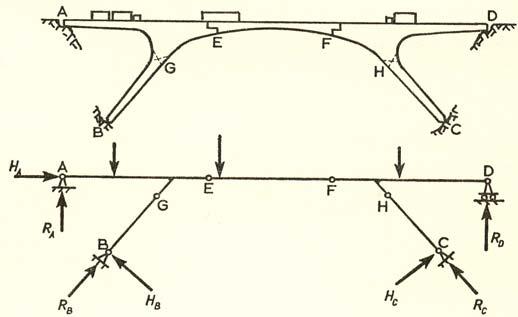
6 Example: Use the theorem of three forces to determine the reactions on the beam. Polygon 1 for the resultant of Ra and Rc Polygon 2 for the equilibrium of the beam a 45 o 60 o 6 tons b Resultant of Ra and Rc Ra Rc 3 m 1 m 3 m Rb d) Types of Supports Supports exert reactions in the direction in which they restrain movement. Roller Support (restricts in one direction only and allows rotation) Rubber Hinged or Pinned Support (restricts in two ways and allows rotation) Fixed Support (restricts in two directions and also restricts rotation) Intermediate Pin or Hinge (Gives one extra condition) Gives extra condition M Right = 0 M Left = 0 Force in direction of member Examples: Dr. Tarek Hegazy 4
7 e) Structural Representation of Real Systems Dr. Tarek Hegazy 5
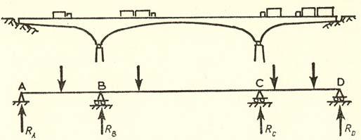
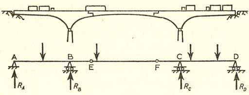
8 f) Stability & Determinacy of Structures - A stable structure can resist a general force immediately at the moment of applying the force. Unstable Does not return to original shape if load is released Stable - A statically determinate structure is when the reactions can be determined using equilibrium equations. 1. Beams: if r < c 3 Unstable r = unknown support reactions. if r = c 3 Statically determinate c = additional conditions if r > c 3 Statically Indeterminate r = 3 (two at hinge one at roller) c = 2 (two intermediate hinges), then, r < c 3 Unstable r = 5 (four at hinges one at roller) c = 2 (two intermediate hinges), then, r = c 3 Stable & Statically Determinate r = c = r =, then 2. Frames: j = No. of joints m = No. of membrs r = unknown support reactions c = special conditions r = 4 (three at fixed end one at roller) c = 0, then r > c 3 Stable & Statically Indeterminate if 3m r < 3j c if 3m r = 3j c if 3m r > 3j c Unstable Statically determinate Statically Indeterminate j = 3; m = 2; c = 0; r = 3 Then, Stable & Statically determinate j = ; m = ; c = ; r = Then, 3m r =, 3j 2 =, or 3. Trusses: j = No. of joints m = No. of membrs r = unknown support reactions if m r < 2j if m r = 2j if m r > 2j Unstable Statically determinate Statically Indeterminate j = ; m = ; r = Then, m r =, 2j =, or j = 8; m = 12; r = 3 Then, m 3 = 15 < 2j, or Unstable Dr. Tarek Hegazy 6
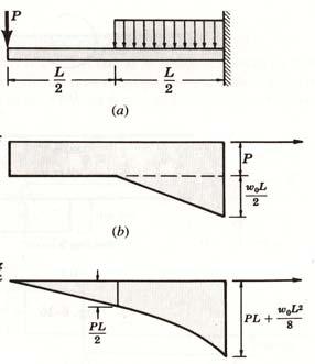
9 2. Analysis of Forces Forces and their effects at different points: Concentrated Load Distributed Load Rotation (Couple) P W t/m M L P1 Effect of a load on another point parallel to its axis = W x L L M = P1. L P P1 b L a Ma = 0 P P b P a Ma = 0 Effect of loads P b M = P x L a Ma = 0 Forces: V M T M P Shear = Force In the X-Section Plane Bending Moment = Couple Normal to Plane Torsion = Couple in the X-Section Plane Normal Force = Perpendicular to X-Section Example: Calculate reactions without applying equilibrium equations P P M = P.L /2 L/2 L/2 L/2 L/2 Dr. Tarek Hegazy 7


10 Example: Determine the forces at section BC 150 lb C M = 150x5 150 lb lb lb.in B 750 lb. in 150 lb 750 lb.in Example: Determine the forces at section A z 8 Note: When the structural system is:, then x A 10 the free end is a good starting point for the analysis. 800 lb 800 lb y T=800x14 Mx=800x10 14 A 500 lb 500 lb Mz=500x14 A lb T=800x14 Equilibrium equations for each segment: Mz=500x lb Mx=0, My=0, Mz=0 Fx=0, Fy=0, Fz=0 800 lb 14 Example: Determine the forces at section HK 500 lb Dr. Tarek Hegazy 8


11 Example: Determine the internal forces at section ABCD Example: Determine the internal forces at section C Example: Determine the forces acting at section D Example: Determine the internal forces on the section Dr. Tarek Hegazy 9
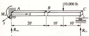
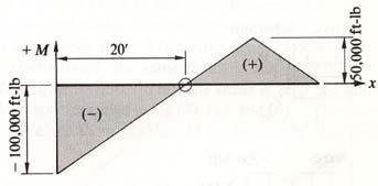
12 3. Internal Loadings on Beams & Frames Sign convention for internal forces (N.F., S.F., & B.M.) ive 3.1 Analytical Approach: Stability & Determinacy Reactions Axis Sections Signs N, V, & M Equations Draw Diagrams Equilibrium Conditions: X Components of all forces = 0 Y Components of all forces = 0 M At any point = 0 Extra condition at intermediate Pin: M r ight side only = 0 = M left side only Analysis of Shear & Moment Equations: F.B.D.: Between load changes, make a cut and put 3 (equal & opposite) internal forces on each side. P Segment 1 Segment 2 M M X X Xa Ya V Cut V Yb Apply Equilibrium Equations to this segment alone Apply Equilibrium Equations to this segment alone Example: Calculate the Reactions 10 t 4 t 8 t a 2 m 1 m 4 Ma 3 Xa Ya a 1 m 1 m 1 m 6 t Step 1: Cantilever beam is stable and statically determinate Step 2: Looking at the system as a whole (right figure) and applying Equilibrium equations, X Y Ma = 0, then Xa 6 = 0, or Xa = 6 t = 0, then Ya 4 8 = 0, or Ya = 12 t = 0, then Ma 4 x 1 8 x 3 = 0, or Ma = 28 m.t. Check OK Dr. Tarek Hegazy 10
13 Example: Calculate the Reactions 3 t 2 t / m Step 1: m = 5; r = 4; j = 6; c = 1 3m 4 = 19 = 3j 1 then, Frame is stable and statically determinate Step 2: Looking at the system as a whole and applying Equilibrium equations, Mb Mc = 0, then 3 x 11 2 x 8 x 7 2 x Xa 9 x Ya = 0 6 m left only = 0 = 3 x 4 Xa x 6 Ya x 2 2 t/m x 4 x 2 = 0 Solving both equations, we get Ya = t, and Xa = 0.76 t Xa a Ya c 2 m 2 m 4 m 3 m, then Yb b Xb 4 m 2 m Y X = 0, then Ya Yb = 0, or Yb = 2.72t = 0, then Xa - Xb = 0 then Xb = 0.76 t Check OK Example: Calculate the Reactions Mb Ma Y = 0 = =. = 0 = =. 2 m 4 m Ya = 0 =. = 0 or Ya = 36 - Yb 4 t 4 m 2 t / m Yb 12 m 4 m Solving these equations, we find Yb = 20 t ; Ya = 16 t ; Xa = Xb = 0 Check OK Example: Calculate the Reactions Mb Y = 0 = = 50x5-4 Ya =0, or Ya = 62.5 t = 0 = Ya Yb - 50 = 0 or Yb = t d 1 m 50 t c Mc right side only = 0 = 4 Yb - 3 Xb or Xb = - 50/3 t 3 m X = 0 = Xa - Xb = 0 or Xa = -50/3 t Check OK Xa 1 m 4 m Ya Yb Xb Dr. Tarek Hegazy 11


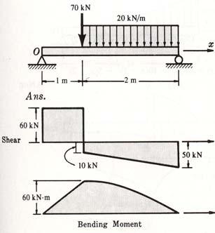
14 Examples: Calculate and draw the S.F.D. and the B.M.D. Reactions: Reactions: Sections: Sections: Solved examples 6-1 to 6-6 Note on simple beam with distributed load: Dr. Tarek Hegazy 12


 - Area under load")


15 3.2 Graphical Approach: Stability & Determinacy - Reactions N, V, & M Relations Draw Diagrams Examples on Page 12 Rules: 1- Shear curve is one degree above load curve 2- Moment curve is one degree above shear curve 3- Moment is maximum at point with shear = 0 4- Between any two points: (look at table) - Area under load = difference in shear - Area under shear = difference in moment - Slope of shear curve = - (load trend) - Slope of moment curve = shear trend Solved examples 6-7 to 6-13 Dr. Tarek Hegazy 13


16 Examples: Calculate and draw the S.F.D. and the B.M.D. ive a b From point a to point b: - Load curve = - Shear curve = - Moment curve = - Area under load = = difference in shear = - Area of shear = = difference in moment = - Shear at point of max. Moment = - Max. moment can be calculated from shear diagram = = - Slope of shear curve = - Slope of moment curve = From point a to point b: a b - Load curve = - Shear curve = - Moment curve = - Area under load = = difference in shear = - Area of shear = = difference in moment = - Shear at point of max. Moment = - Max. moment can be calculated from shear diagram = = - Slope of shear curve = - Slope of moment curve = Dr. Tarek Hegazy 14
17 ive Examples: For the problems in page 12, draw the N.F.D., S.F.D., & the B.M.D. 1 m d 50 t c 4 t 2 2 t / m 0 3 m /3 50/3 4 m 0 12 m 4 m 1 m 4 m Dr. Tarek Hegazy 15


18 Examples: Calculate and draw the S.F.D. and the B.M.D. ive Dr. Tarek Hegazy 16


19 4. Stresses due to Forces Internal Forces: Normal Moment Shear Torsion M V T P M Normal Force = Perpendicular to X-Section Bending Moment = Couple Normal to Plane Shear = Force In the X-Section Plane Torsion = Couple in the X-Section Plane Stresses - τ A Q = A. Y In narrow rectangular beams, τ max = 1.5 V / A Dr. Tarek Hegazy 17


20 Example: Draw the S.F.D. and the B.M.D. for the beam below and then determine the maximum normal stress due to bending. Example: Draw the S.F.D. and the B.M.D. for the beam below and then determine the maximum normal stress to the left and to the right of point D. The beam has a section modulus of 126 in3. Example: Page 8 of notes - Determine the internal stresses at points B & C 150 lb C 150 lb 750 lb.in B I = 4 x 10 3 / 12 ; σ B = / A 750 x 5 / I = 7.5 psi ; σ C = / A x 5 / I = psi Dr. Tarek Hegazy 18


21 Example: Calculate normal stresses at section d and also at the section just below c. First, we get the reactions. Example: Determine the internal stresses at points A, B, C, & D B C VQ / It = 0.5 MPa D A B V = 3 KN T = 3 KN My = 10.5 KN.m C B A C T.c / J = 15.3 MPa D D My = 10.5 lb.in M. x / I = 107 MPa C A B D A Dr. Tarek Hegazy 19
")


22 Example: Page 8 of notes = Example: The timber used in the beam below has an allowable stresses of 1800 psi (normal) and 120 psi (shear). Determine the minimum required depth d of the beam. From the S.F.D. and the B.M.D., maximum values of: Moment = 7.3 Kip.ft = 90 Kip.in; Shear = 3 Kips Design based on allowable Normal stress: Check Shear stress: Redesign based on allowable shear stress: >120 (unacceptable) Solved Problems 6-14 to 6-20, 7-1 to 7-3, 8-4 to 8-6 Dr. Tarek Hegazy 20
 / (A / Cos θ) or Very important conclusions: - Under tension only, shear is automatically present at various planes.")


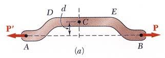
23 5. Transformation of Stresses - Member under tension only (P) in one direction, i.e., a normal stress. But, let s consider an inclined plane. σ θ = (P Cos θ) / (A / Cos θ) or Very important conclusions: - Under tension only, shear is automatically present at various planes. - The plane of maximum shear is when Sin 2θ = max or when θ = Maximum shear = σ x /2 = P / 2A - It is important to study stress transformation and shear failure. σ θ = σ x Cos 2 θ τ θ = ½ σ x Sin 2θ - Member under two dimensional stresses. Positive Signes y σ y τ xy σ x x Questions: Is this the maximum stress? If not, then What is the value of max. normal stress & its orientation? and What is the value of maximum shear stress & its orientation? y' σ y τ x y σ x x' θ x General Equations: 75 MPa Example: For the given state of stress, determine the normal and shearing stresses after an element has been rotated 40 degrees counter-clockwise. 60 MPa 30 MPa σ x = 30 MPa ; σ y = -75 MPa ; τ xy = 60 MPa ; θ = 40 Applying the above equations, we get: σ x = 45.7 MPa ; σ y = MPa ; τ x y = MPa y' x' 40 x Solved Examples 9-2 to 9-6 Dr. Tarek Hegazy 21
24 Important Observations: 1. σ x σ y = σ x σ y = Constant Sum of normal stress is constant (90 degrees apart) for any orientation. 2. The plane in which shear stress τ x y = 0 is when: or tan 2θ = 2 τ xy / (σ x - σ y ) or at θ 1, θ 2 having 90 degrees apart. These are called principal planes. = 0 3. σ x becomes maximum when dσ x / dθ = 0, or when differentiating the following equation: we get, tan 2 θp = 2 τ xy / (σ x - σ y ) or, exactly at the principal planes, which has shear stress = 0. The value of the principal normal stresses are: σ max, min = σ x σ y ± 2 ( σ x - σ y ) 2 τ 2 xy 2 4. Since σ x σ y = constant, then, at the principal planes, σ x is maximum but σ y is minimum. 5. τ x y is maximum when planes, dτ / dθ = 0, or when: tan 2 θs = - (σ x - σ y ) / 2 τ xy and the value of maximum shear stress τ xy is: τ x y max = ( σ x - σ y ) 2 τ 2 xy 2 6. Similar to single stress situation, maximum is when dτ / dθ = 0, or when: θ =. Example: Check rule 1 for the example in previous page. In the general equations, even if the original τ xy on the element = 0, then still the shear at any plane (τ x y )has a value as a function of normal stresses. Dr. Tarek Hegazy 22


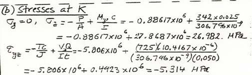
25 Example: Determine the maximum normal and shear stresses at point H. Forces at the section: Stresses at Point H: Principal stresses: Example: Determine the maximum normal and shear stresses at points H & K. Dr. Tarek Hegazy 23


26 Example: Determine the maximum normal and shear stresses at points H & K. Dr. Tarek Hegazy 24
27 Circular representation of plane stresses (Mohr s Circle): y Step 1: Given a state of stress, with σ x and σ y having 90 degrees apart. σ y τ xy σ x Step 2: Let s plot the σ x and σ y on a horizontal line Notice, the 90 degrees are now 180 apart. x 0 σ y θ σ x σ Step 3: Let s plot the σ x and σ y on a horizontal line then τ xy vertically at points 1 and 2 using signs. 0 τ Y (?,? )? τ xy σ y???? σ x τ xy X (?,? ) σ σ y Y X τ xy σ x Step 4: Draw a circle from the center to pass by points 1 and 2. Determine σ max, σ min, θ p, τ max, θ s? σ y Y Y X τ xy σ x 0? σ y σ x?? σ X Solved Examples 9-7 to 9-13 τ Dr. Tarek Hegazy 25
28 Example: For the given state of stress, determine the normal and shearing stresses after an element has been rotated 40 degrees counter-clockwise. 75 MPa 60 MPa 30 MPa Y (-75,60) X θ2 θ1 80 o 30 σ Y X Y X (30, -60) From the figure: Average stress = Center of circle = (30 75)/2 = -22.5, R = sqrt ( ) = 79.7 tan θ1 = 60 / 52.5, then θ1 = 48.8 o and θ2 = 80 - θ1 = 31.2 o Then, points X and Y have the following coordinates: σ x = R cos θ2 = * = 45.7 MPa σ y = R cos θ2 = MPa ; τ x y = R sin θ2 = MPa Principal stress values: σ max, σ min = Average ± R = ± 79.7 = 57.2, Example: For the given state of stress, determine: a) principal planes; and b) principal stresses. Analytically: σ x = -40 MPa; σ y = 60 MPa ; τ xy = 25 MPa tan 2θ p = 2 τ xy / (σ x - σ y ) = 2 x 25 / (-40-60) = -0.5 or at θ p1 = ; θ p2 = 76.7 σ max, σ min = Average ± R = Graphically: Two points X & Y Center = R = σ max, σ min = Average ± R Y σ x σ y ± 2 X (-40, -25) ( σ x - σ y ) 2 τ 2 xy 2 2θ = 10 ± 55.9 MPa Y (60,25) σ 60 MPa 25 MPa 40 MPa Y X 40 x Dr. Tarek Hegazy 26
29 Example: You have a Mohr circle of stress as shown below for two separate points. Draw the stresses on each element and its orientation from principal planes. 40 A (50,? ) R =? σ Y A (50, y ) 40 y 50 x = 50 Y 16.8 R = 60 Y = sqrt ( ) = 33.2 Tan 2θ = y / 50 or 2θ = 33.6 o θ 160 σ A (150, -y ) Y 100-X X 40 B (100-X, 40 ) y = 40 R = 60 x 100 B (?, -40 ) 2θ 160 B (100 X, -40 ) X = sqrt ( ) = 44.7 Tan 2θ = 40 / X or 2θ = 83.6 o σ Special Cases: 1. Case of pure tension A member under one directional stress σ x = P / A and σ y = 0 Let s use Mohr s circle. From Mohr s circle, maximum shear τ max = σ x / 2 = P/ 2A Maximum shear is at 45 degrees. τ max Y X 0 σ x y' σ y Y X τ max σ x σ x x' Case of pure torsion A member under only torsional stress, with σ x = 0 and σ y = 0, Let s draw Mohr s circle. Y X τ xy Y As seen, torsional stress creates normal Stresses which are maximum at 45 degrees. 0 σ max σ X Dr. Tarek Hegazy 27
30 Graphical representation of principal planes: Properties of a circle: an angle 2θ at the center of the circle, corresponds to an angle θ at the circumference. θ θ = 90 2θ 2θ = 180 Special case 5 Y (5,20) 20 Y X θ p 30 σ X (30, -20) Plane of principal normal stress Plane of maximum shear stress Y σ = -6.1 min Y 5 2θ p 30 5 σ max = θ s 30 θ p X θ s X Dr. Tarek Hegazy 28
31 3-Dimensional stress systems: (Absolute maximum shear stress) Assume σ1 > σ2 > σ3 are principal normal stresses ( no shear), then let s draw Mohr s circle. τ max σ 2 σ 1 σ3 σ2 σ1 σ σ 3 Note : Even if σ3 = 0, 3-D stress analysis becomes essential. Case 1: both σ1 and σ2 are positive Case 2: both σ1 and σ2 are negative Then, τ max = σ1 / 2 Then, τ max = σ2 / 2 τ max τ max σ2 σ1 σ2 σ1 Case 3: σ1 and σ2 have opposite signs Then, τ max = (σ1 - σ1) / 2 τ max σ2 σ1 Examples Dr. Tarek Hegazy 29

 Is this the maximum strain?")

32 6. Transformation of Plain Strain - A structure should be designed so that its material and cross sectional dimensions can resist the maximum normal and shear stresses imposed on it. Equally important also that the structure does not deform much under the load, i.e., the ability to resist strains is crucial to the serviceability of structures. - Normal Strain (due to axial load bending moment) and Shear Strain (due to transverse shear torsion). Normal Strain Shear Strain = Questions: Strain = ε = Unitless = L / L Positive Signs (elongation and angle) Is this the maximum strain? If not, then What is the value of maximum normal strain and the plane in which it exists? and What is the value of maximum shear strain and the plane in which it exists? - General equations for strains on a plane at angle θ for a member under two dimensional strain. Notice that all equations look the same as those of stress transformation, except that τ xy is resembled by : General Equations: Given the three constants,, then, Normal strain at any angle θ: Shear strain at any angle θ: Principal (Normal) Strain: Orientation: Max. Value: Shear strain at this plane: Zero Maximum Shear Strain: Orientation: Max. Value: Solved Problems 10-1 to 10-8 Normal strain at this plane: Dr. Tarek Hegazy 30
33 - Strains before and after transformation: Positive Strains Negative Strains Positive Strains at positive angle θ at negative angle θ at θ = 0 θ Important Observations: 1. ε x ε y = ε x ε y = Constant (90 degrees apart) for any orientation. 2. The plane in which shear strain γ x y / 2 = 0 is when: = 0 or tan 2θ = γ xy / (ε x - ε y ) or at θ 1, θ 2 having 90 degrees apart. These are called principal planes. 3. ε x becomes maximum when dε x / dθ = 0, or when differentiating the following equation: we get, tan 2 θp = γ xy / (ε x - ε y ) or, exactly at the principal planes, which has shear strain = γ x y is maximum when dγ / dθ = 0, or when: tan 2 θs = - (ε x - ε y ) / γ xy 5. Similar to single stress situation θs = 45 o from θp. 6. Mohr s circle of strain: γ/2 Y (εy, γ/2) Y X 2θ p ε X (εx, - γ/2) ε min?, ε max?, γ max?, θ p?, θ s? Dr. Tarek Hegazy 31
34 Example: Given ε x = -200 x10-6, ε y = 1000 x10-6, γ xy = 900 x10-6. Find the strains associated with x y axes inclined at 30 degrees clockwise. Find principal strains and the maximum shear strain along with the orientation of elements. Solution First, we sketch the element with the given strains, as follows. Y X Then, we define two points X and Y to draw Mohr s circle. γ/2 x10-6 Shorter in X Longer in Y ive shear strain X (-200, -450) R= Y (1000, 450) 600 ε x10-6 2θ p R = Sqrt (60^2 450^2) = 750 Principal Strains: εmax, εmin = 400 ± 750 = 1150 x10-6, -350 x10-6 γx y at principal planes = 0 2θ p = tan -1 (450 / 600) = 36.8 o Max Shear Strains: γmax / 2 = R = 750 x10-6 εx = εy at Max shear plane = 400 x10-6 2θ s = 36.8 o 90 = o γ/2 x10-6 α = = 23.2 Then εx = R Cos α = x Cos 23.2 = -290 x10-6 γx / 2 = R Sin α = 750 Sin 23.2 = 295 x10-6 X (, ) R=750 α ε x o α 400 Y εy = 400 R Cos α = x Cos 23.2 = 1090 x10-6 γy / 2 = -R Sin α = -750 Sin 23.2 = -295 x10-6 X R=750 Y (, ) At 30 o Clockwise At Principal Planes At Maximum Shear Plane Y Y X θ=30 o Shorter in X Longer in Y -ive shear strain (clockwise rotation) θp=18.4 o Shorter in X Longer in Y No Shear strain θs= o X Longer in X Longer in Y -ive shear strain Dr. Tarek Hegazy 32
35 Absolute maximum shear strain Assume ε1 > ε2 > ε3 are principal normal strains (no shear), then let s draw Mohr s circle. γ/2 γ max /2 Note: Even if ε3 = 0, 3-D analysis is essential. Case 1: both ε1 and ε2 are positive Then, γ max /2 = ε1 / 2 ε3 ε2 ε1 ε γ/2 γ max /2 ε2 ε1 γ max /2 = (ε max - ε min ) / 2 Case 2: both ε1 and ε2 are negative Case 3: ε1 and ε2 have opposite signs Then, γ max /2 = ε2 / 2 Then, γ max /2 = (ε1 - ε2) / 2 γ max /2 γ/2 γ/2 γ max /2 ε2 ε1 ε2 ε1 Solved Examples: 10-1 to 10-7 Dr. Tarek Hegazy 33

36 Strain Measurements Using Strain Rosettes: - 45 o strain rosette versus 60 o strain rosette - Cemented on surface - Its electrical resistance changes when wires are stretched or compressed with the material being studied - Resistance changes are measured and interpreted as changes in deformation - Three values to get the state of strain at the point - Automated condition assessment of bridges - Check the strains on older structures or εx = εx cos 2 θ εy Sin 2 θ γxy cos θ. Sin θ Readings: εa, εb, εc At: θa=0, θb=45, θc=90 Unknowns: εx, εy, γxy Applying into the general equation: εx = εa εy = εc γxy= 2εb (εa εc) Readings: εa, εb, εc At: θa=0, θb=60, θc=120 Unknowns: εx, εy, γxy Applying into the general equation: εx = εa εy = (2εb 2εc - εa) / 3 γxy= 2(εb εc) / Sqrt(3) Substitute into either equation 3 times using εa, εb, εc to get the unknowns εx, εy, γxy at the measurement point. Example: Using the strain rosette shown, the measured values at each stain gauge is as follows: b a εa = 8 x 10⁻⁴, εb = -6 x 10⁻⁴, εc = -4 x 10⁻⁴ Determine the principal strains at the point. c Solution Using Equations: θa = 90, θb = 135, θc = 180 Applying into the general strain transformation equation: εa = 8 x 10-4 = εx cos 2 90 εy Sin 2 90 γxy cos 90. Sin 90 εb = -6 x 10-4 = εx cos εy Sin γxy cos 135. Sin 135 εc = -4 x 10-4 = εx cos εy Sin γxy cos 180. Sin 180 Then: εy = εa = 8 x 10⁻⁴ ; εx = εc = -4 x 10⁻⁴ ; γxy /2 = 16 x 10-4 Using Mohr s circle, we determine principal strains: ε1 = 12 x 10-4 ; ε2 = -8 x 10⁻⁴ γ/2 x10-4 A R=10 16/2-4 ε x /2 C Solution Using Only Mohr s Circle: γ/2 x10-4 A Directions (a) and (c) are 90 degrees apart This means that the center of the circle is the Average strain = (εa εc) / 2 = (8 x x 10-4 ) /2 = 2 x 10⁻⁴ From the two triangles shown, d =, Then, R = Sqrt( d ) = As such, B -6 2θp R R 8 2θp 2 6 d =? 8 ε x10-4 ε1 = 2 R = 12 x 10-4 ; ε2 = 2 R = -8 x 10⁻⁴ C Dr. Tarek Hegazy 34
. Y X? Longer in X Shorter in Y ive shear strain.?? Dr.")
37 Example: Solution: Strategy: We draw a Mohr s circle for strain and on it will find the strains at the orientations of the strain gauges (45o apart). Y X? Longer in X Shorter in Y ive shear strain.?? Dr. Tarek Hegazy 35

; E.εy = σy - ν (σx σz); E.εz = σz - ν (σx σy); G. γxy = τxy G. γyz = τyz G.")

38 7. Relationship between Stress & Strain - A stress in one direction causes elongation in its direction and shortening in the other two depending on the material s Poisson s ratio (ν). Generalized Hooke s law εx = σx / E εx = - ν. σy / E εx = εy = - ν. σx / E εy = σy / E εy = εz = - ν. σx / E εz = - ν. σy / E εz = - Assumptions: (1) τ has not correlation with εx and εy; (2) σx and σy have no relation with γxy ; (3) principal strains occur in directions parallel to principal stresses. -General Equations: E.εx = σx - ν (σy σz); E.εy = σy - ν (σx σz); E.εz = σz - ν (σx σy); G. γxy = τxy G. γyz = τyz G. γzx = τzx - Relationship between E, ν, G: Let s consider the case of pure torsion, i.e., σ x = 0 and σ y = 0, Let s draw Mohr s circles for both stress and strains. τ Y γxy/2 Y 0 σ max σ 0 ε max ε X X Principal stresses are: σ 1 = τxy ; σ 2 = - τxy Principal strains are: ε 1 = γxy/2 ; ε 2 = - γxy/2 Now, let s apply Hook s Equation, as follows: E.ε1 = σ1 - ν (σ2) ; then E.ε1 = E. γxy/2 = τxy - ν (- τxy) = τxy. (1 ν) = G. γxy. (1 ν) Then, Bulk Modulus G = E / 2 (1 ν) K = E / 3 (1-2 ν) Note: Since most engineering materials has ν = 1/3, then G = 3/8 E and K = E Dr. Tarek Hegazy 36

39 Example: Notice the difference between Mohr s circles for stress & strain Example: Example: Example: Dr. Tarek Hegazy 37


 If the bracket is made of")


40 Example: Example: Match each one of the following Mohr s circle for stress with a Mohr s circle for strain. Explain. Example: A 60 degree strain rosette is put at point A. The strain guage readings are: εa = 60x10-6 εb = 135x10-6 εc = 264x10-6 a) Determine the Principal strains at point A and their directions. b) If the bracket is made of steel for which E = 200 GPa and ν = 0.3, determine the Principal stresses at point A. Solution: Approach: from strain rosette readings, we get strains at the point, then calculate principal strains and finally convert these principal strains into principal stresses. Dr. Tarek Hegazy 38

 / 2 = 153x10-6")


41 a) First, we determine the normal and shear strains at point A from rosette readings. Accordingly, Second, we determine principal strains using Mohr s circle. Center of circle = average normal strain = (60 246) / 2 = 153x10-6 Accordingly, Principal strains = 153 ± R = 272 x10-6 ; 33 x10-6 b) Using Hooke s law with σ 3 = 0 Another Solution: Approach: from strain rosette readings, we get strains at the point, then we convert them into stresses and finally calculate principal stresses. First, we calculate strains at point A, same as above. Then, Now, we convert these strains to stresses: Dr. Tarek Hegazy 39


42 We now can use Mohr s circle for stress to determine Principal stresses: Example Solution Approach: Since we are given the forces, let s calculate the Stresses at point P, then, convert these stresses into strains. Forces on Section at P. Forces at end of beam. Stresses at Point P: Normal stresses Dr. Tarek Hegazy 40


43 Shear Stresses Strains at Point P: Example: Forces at section of Point A: Stresses at point A: ` Strains at point A: Dr. Tarek Hegazy 41
44 Mohr s circle of Strain: Strain Gauge Readings: Solved Problems 10-9 to Dr. Tarek Hegazy 42
 - Max.")
 - Other: Max. principal strain (St.")
 Principal stresses σ2 σ1 Failure when: σ1 > σy / F.")
 -σy -σy σy σ1 Max.")

45 8. Theories of Failure Ductile Material (Yield Failure) All theories deal with PRINCIPAL STRESSES Brittle Material (Fracture Failure) - Max. normal stress (Rankin s Theory) - Max. shear stress (Tresca Criterion) - Max. Energy of Distortion (Von Mises Criterion) - Other: Max. principal strain (St. Venant) Max. normal stress (Rankin s Theory) Principal stresses σ2 σ1 Failure when: σ1 > σy / F.S. or σ2 > σy / F.S. where F.S. > 1 σ2 σy A state of plane stress Is safe inside the square And unsafe outside (assume tension = compression) -σy -σy σy σ1 Max. shear stress (Tresca Criterion) A specimen under tension reached maximum stress σy, then, the maximum shear that the material can resist is σy /2 from Mohr s Circle. Then, failure is when τ Absolute max. shear (3-D analysis) = σ max σ min /2 > σy / (2 * F.S.) Dr. Tarek Hegazy 43

![ε For the 3-D stress Case: 1 [(σ1 σ2) 2 (σ2 σ3) 2 (σ3 σ1) 2 ] < 2 σ 2](/docs-images/77/75795148/images/46-1.jpg "yield 12G 12G or Simply, (σ1 σ2) 2 (σ2 σ3) 2 (σ3 σ1) 2 < 2 σ 2 yield For")


46 Energy of Distortion (Von Mises Criterion) To be safe, U d on element < U d yield U = ½ σ.ε For the 3-D stress Case: 1 [(σ1 σ2) 2 (σ2 σ3) 2 (σ3 σ1) 2 ] < 2 σ 2 yield 12G 12G or Simply, (σ1 σ2) 2 (σ2 σ3) 2 (σ3 σ1) 2 < 2 σ 2 yield For the 2-D stress Case: (σ3 = 0) (σ1 2 σ1 σ2 σ2 2 ) < σ 2 yield Other: Max. principal strain (St. Venant) Rarely used Using Hooke s law E ε max = σ1 ν (σ2 σ3) < σ yield Fracture of Brittle Materials Brittle materials are relatively weak in Tension. Failure criterion is Maximum Principal Tensile Stress. Under Tensile force, failure is due to tension. Under Torsion, failure is still due to tension at an angle. Element is safe when: Example: Twist of a piece of chalk. Solved Examples to Dr. Tarek Hegazy 44
 Principal Stresses σx = P / A = P /π (0.0225) 2 τxy = T.c / J = 1.7 x (0.0225) / ½ π (0.0225) 4 = 95.")
47 Example: A steel shaft (45 mm in diameter) is exposed to a tensile yield strength = σyield = 250 MPa. Determine P at which yield occurs using Von Mises and Tresca critera. Solution 1) Principal Stresses σx = P / A = P /π (0.0225) 2 τxy = T.c / J = 1.7 x (0.0225) / ½ π (0.0225) 4 = Mohr's circle: Center = σx / 2 R = [(σx/2) 2 τxy 2 ] ½ σ1 = σx / 2 R; σ2 = σx / 2 - R T = 1.7 KN.m P? σx 2) Using Von Mises σ1 2 σ1σ2 σ2 2 = σ yield 2 (σx / 2 R) 2 (σx / 2 R) (σx / 2 - R) (σx / 2 - R) 2 = σ yield 2 (σx/2) 2 3 R 2 = σ yield 2 σx 2 3 τxy 2 2 = σ yield, substituting with R,, substituting with σx & τxy, X [P /π (0.0225) 2 ] 2 3 x (95.01) 2 2 = σ yield = then, P = KN 3) Using TRESCA σ1 and σ2 have opposite signs, then τ max (3-D) = σ1 - σ2 / 2, which reaches failure of τ yield = σ yield / 2 (σx/2 R) - (σx/2 - R) / 2 = σ yield / 2 then, R = σ yield / 2, substituting with R and squaring both sides, (σx/2) 2 τxy 2 = (σ yield / 2) 2, substituting with σx & τxy, [P /2 π (0.0225) 2 ] 2 (95.01) 2 = then, P = KN Notice the force P under TRESCA (focuses on Shear) is smaller than Von Mises Dr. Tarek Hegazy 45
 needs to be studied.")
48 Deflection of Beams and Shafts Beams and shafts deflect under load. For serviceability, we need to make sure deflection is within allowable values. Also, the shape of the beam under the load (elastic curve) needs to be studied. Terminology: - EI = Flexture rigidity or Bending Stiffness - R = Radius of Curvature - 1/R = Curvature υ - Hookes Law: 1/R = M / EI - The elastic curve: dθ R y R Rdθ = ds dx or 1/R = dθ/dx Also, dυ/dx = tan θ θ Differentiating both sides, then d 2 υ/dx 2 = dθ/dx θ ds θdθ ds θ dx dυ Notes: Accordingly, 1 = M = dθ = d 2 υ R EI dx dx 2 - Integration of (M/EI) determines the slope of the elastic curve: - Double integration of M/EI determines the deflection: - Recall relationships between load, shear, and bending moment. Now, we can expand it to: EI d 2 υ/dx 2 = M(x); EI d 3 υ/dx 3 = V(x); EI d 4 υ/dx 4 = -W(x) Determining the integration constants C1 and C2: Substituting at points of known deflection and/or slope, we can determine the constants of integration. Dr. Tarek Hegazy 46

49 Shape of Elastic Curve: inflection point at location where moment=0 Calculating Slope & Displacement by Integration: Step-by-Step 1. Get beam reactions: X = 0, Y = 0, M = 0 2. Get equation of B.M. at each beam segment with change in load or shape 3. Integrate the moment once to get the slope 4. Integrate the moment a second time to get the deflection (elastic curve) 5. Substitute at points of special conditions (boundary conditions) to get the constants C1 & C2 6. Rewrite the slope and deflection equations using the constants 7. Put slope = 0 to determine the location (x) that has maximum deflection Example: For the part AB, determine the equation of the elastic curve and maximum deflection if: I = 301x10 6 mm 4, E=200 GPa, P=250 KN, a = 1.2 m, L = 5 m. P Ya L Yb a Dr. Tarek Hegazy 47
50 Solution 1. Reactions: M a = 0 Yb. L - P. (L a) = 0 or Yb = P (1 a/l) P Y = 0, then Ya Yb P = 0 or Ya = - P. a/l P.a/L P(1 a/l) 2. Bending moment equations: Mx x 0 to L V P.a/L Mx = - P.a.x / L Fx Fx P Mx x = 0 to a V Mx = - P. x 3. Integrate the moment to get the slope: 8. Applying same steps at the free end: = - P.a.x 2 / 2L C1 = - P.x 2 /2 C3 (3) 4. Integrate a second time to get the (elastic curve) = - P.a.x 3 / 6L C1. x C2 = - P.x 3 / 6 C3. x C4.(4) 5. Substitute at points of known conditions 6. Final equations: at support A: [x = 0. y = 0] then, C2 = 0 also, at support B: [x = L, y = 0] then, 0 = - P a L 3 / 6L C1. L or C1 = P.a.L/6 = - P.a.x 2 / 2L P.a.L /6 (1) = - P.a.x 3 / 6L P.a.L.x /6... (2) 7. Put slope = 0 at maximum deflection 0 = - P.a.x 2 / 2L P.a.L /6 get x = 0.577L Slope at B right = Slope at B Left Slope left = using equation (1), x=l = -P.a.L/2 P.a.L/6 Slope right = using eq. (3), x=a = -P.a 2 /2 C3 we get C3 Also, at B: [x = a, y = 0] Using Equ. (4), we get C4 Using this value in equation (2), we get Max deflection = 8 mm Up. Solved problems 12-1 to 12-4 Dr. Tarek Hegazy 48


.")
51 Calculating Slope & Displacement by Moment Area Method: 1 st Moment Area Theorem: Recall M = dθ EI dx Then, θ B/A = X A X B change in slope M EI dx area under M/EI diagram 2 nd Moment Area Theorem: t BA = (vertical distance from B on elastic curve to tangent at A) = Moment of the area under M/EI around point B. d B = d B. M dx EI X A X B Note: t AB = t BA Case 1: Cantilever Notice that tangent at point A is horizontal. -Deflection at any point: -Slope at any point: θ B/A = M dx = θ B - θ A = θ B EI X A X B θ A = Case 2: Symmetric Loading Option 1 Deflection is max at mid beam (C). At this point θ C = -Deflection at any point: -Slope at any point: X d θ B/A = M dx = θ D - θ C = θ D EI X C A C θ C = C = d d t dc B t BC Dr. Tarek Hegazy 49
52 Case 3: Unsymmetrical Loading Option 2 L1 L2 -Deflection at any point: d t DA = t BA. L1/(L1L2) A d B -Slope at any point to the right: d θ D/A = M dx = θ D - θ A with θ A being negative = θ D θ A EI X a X d t BA / (L1L2) A t DA t BA A L1 d θ A d L2 B θ D θ A t DA t BA A -Slope at any point to the left: θ A θ D/A = M dx = θ D - θ A, both negative = θ A - θ D EI X a X d t BA / (L1L2) θ D Case 4: Over-Hanging Beam L1 θ B = t AB / L1 A heavy load θ B B C t CB c = ( c t CB ) / L2 L2 t AB Then, c = θ B. L2 - t CB t BA t CA = t BA. (L1L2)/L1 A θ A B C Then, c = t CA - L1 L2 heavy load c Dr. Tarek Hegazy 50
53 Case 5: Unsymmetrical Loading Point of Max. Deflection θ B = t AB / L A x =? B t BC X B θ B/C = M dx = θ B - θ C = θ B = t AB / L EI X C We get x, then C = max = t BC t BA C θ C = 0 C = max Note: Equivalence in Bending Moment Diagrams a -b a = = a ive -ive -b -a Method of Superposition: - Using Standard tables for various beam conditions and types of loads (Appendix C) - Adding up deflections caused by individual loads Solved Problems: 12-7 to Dr. Tarek Hegazy 51
 / 4 A θ C t DC A 600 t AC = 1/EI [600. 4/2. 2/3. 4] t AC Example: Determine θ A and D A B wl/6 D wl/3 θ A = t BA / L = Moment of M/EI @ B / L B.M.D. 3 rd degree = [w.")
54 Example: Determine θ C and A A 150lb 4 L1 300lb C D B lb 400 lb 600 D M/EI 600 t DC =1/EI [ (600 x 24 /2). 2/ (1800 x 24 /2). 1/3. 24 ] θ C = t DC / 24 = ( A t AC ) / 4 A θ C t DC A 600 t AC = 1/EI [600. 4/2. 2/3. 4] t AC Example: Determine θ A and D A B wl/6 D wl/3 θ A = t BA / L = Moment of B / L B.M.D. 3 rd degree = [w.l 2 /6EI. L/2. L/3 - w. L 2 /6EI. L/4. L/5] / L = 7 w.l 3 / 360EI wl 2 /12 = wl 2 /6 Also, d t DA = t BA / 2 Then A θ A 3 rd degree d d L/5 -wl 2 /6 B d = t BA / 2 - t DA = 7 w.l 3 /720EI L/2 -wl 2 /48 - [1/2.w.L 2 /12EI.L/2.L/6 - ¼. wl 2 /48EI. L/10] = 5 w.l 4 / 768EI t DA t BA Dr. Tarek Hegazy 52
55 Using Deflection Calculations to Solve Statically Indeterminate Beams P P = 1 2 =0 R B? statically indeterminate P = M A? θ1 θ2 =0 First, we reduce the beam to a statically determinate, then We compensate for the change in the deflection behavior. Example: A 6 ft 12 Kips 3 Kip/ft B 6 ft 12 ft Determine the reactions, then draw the S.F.D. & the B.M.D. C 12 Kips = 3 Kip/ft 1 A 1 B C t AC t BC R B 2 2 = - R B L 3 / 48 EI 1 2 =0 Dr. Tarek Hegazy 53


56 Example: Solution: Dr. Tarek Hegazy 54
 U e = ½ P.")

57 Energy Methods - For a structural element under load and deformation, External Work U e = Internal Strain Energy U i. - External work U e is a function of the load P and deflection. (deflection is at same point and direction of load) U e = ½ P. - Also, the Internal strain energy in the structure U i is a function of the stress σ and strain ε in the element, summed over the volume of the structure. U i = ½ σ. ε. V = σ 2 Strain Energy per unit volume 2E. V σ ε Normal Shear L U i = σ 2. dv and U i = τ 2. dv V = dv = da dx 2 E 2 G v v v A 0 L when A is constant, Observe the units. Strain Energy calculations for different loading conditions are shown in next page. V = A dx 0 Determining Deflections Using Conservation of Energy Single External load Deflection in the direction of load: U e = U i U e = ½ P. & U i = U e = ½ M o. θ & U i U e = ½ P. & U i Limitations: Applies to single load only. Also, in case 2, only solpe is calculated not deflection. Also, how to get deflection at a point at which no direct load is applied. Solved Examples 14-1 to 14-7 Dr. Tarek Hegazy 55
58 Strain Energy Calculations Axial Load U i = σ 2. dv = N 2 da dx 2E 2EA 2 v A 0 L Normal Stress Example: Truss with varying axial loads on individual members. (Cross section area A is constant, then V = A. L) Bending Moment L U i = σ 2 /2E dv or U i = M 2. y 2 da dx v 2 E I 2 A 0 σ = M.y I = I L U i = M 2 dx 2 E I 0 Shear Stress Pure Shear U i = ½ τ. γ. dv = τ 2 /2G A. dx v 0 τ = V.Q L I.t L U i = fs V 2 dx where, fs = 6/5 - rectangular section 2 G A 0 Torsion U i = ½ τ. γ dv = τ 2 /2G. da. dx v A 0 L τ = T.c J U i = T 2 dx 0 2 G J L Dr. Tarek Hegazy 56
59 Example: Determine the strain energy due to both shear and bending moment in the following cantilever. The cross section is a square of length a, with EI being constant. w P Example: Determine deflection at C, neglect shear strain energy.. 2EI EI L/2 L/2 C Dr. Tarek Hegazy 57
60 Principle of Virtual Work Conservation of Virtual Work Work-Energy method is not able to determine the deflection at a point at which no direct load exists.? Solution: Put a virtual load of 1.0 at the desired point of a virtual system. Then apply the principal of conservation of virtual work, as follows: Real Beam Virtual Beam 1.0? External Virual WorK = Internal Virtual Energy ½ Virtual load x Real displacement = ½ Virtual Stress x Real Strain x Volume L 1.0 x = σ V. ε R. V = σ V. σ R. da dx E A 0 L L = n N A dx = n N dx Axial A A E 0 0 A E Load L m M dx Bending 0 E I L fs v V dx Shear 0 GA L t T dx Torsion 0 G J Examples: Real Virtual Determine slope at desired point 2. Determine horizontal deflection at desired point Solved Examples to Real N M V T Virtual n m v t 1.0 Dr. Tarek Hegazy 58
61 Example: Determine the deflection at mid span. w Example: Get deflection at A. w L/2 L/2 A Dr. Tarek Hegazy 59
62 Example on Virtual Work - determine the vertical deflection at point A. A 3 t/m Determine the horizontal deflection at point A. A Dr. Tarek Hegazy 60
63 Calculate: The horizontal displacement at point B. Vertical displacement at point C. Slopes at points A, C, and D. Relative displacement between points E and F. EI = Constant 3 m 4 KN 2 KN / m D E 4 KN / m C F 4 m A B 4 m 2 m 4 m 2 m Dr. Tarek Hegazy 61
64 Suggested Problems Calculate the vertical deflection at point d. EI = 20,000 m2.t Calculate: - The horizontal displacement at point b, - The vertical displacement at point g - The slope at point f EI = 20,000 m2.t For the shown frame calculate: - The vertical deflection at point c - The horizontal deflection at point d EI = 15,000 m2.t For the second problem, assume support B is hinged. In this case, draw the S.F.D. and the B.M.D. for the frame. Dr. Tarek Hegazy 62
65 Important Use of the Virtual Work method: SOLVING statically indeterminate structures A w B C L/2 L/2 1 R B 2 = 0 Reduced System Compensation w = 1 2 R B. 1.0 Also, w L/2 L/2 = Reduced System θ 1 w θ 1 M A θ 2 = 0 Compensation M A. 1.0 θ 2 Examples: Dr. Tarek Hegazy 63

66 Calculating Deflections Using Castigliano s Theorem - Put an external load at the position of required deflection: external load (Q) either horizontal or vertical to get horizontal or vertical deflection; or an external moment to get slope. - Deformation = first derivative of the Strain Energy with respect to the applied load. = du / dq, & substituting Q = 0 = δ N 2 dx = N δ N dx Axial Load (Trusses) δq 2EA EA δq = δ M 2 dx = M δ M dx Bending Moment δq 2 E I E I δq 0 = δ fs V 2 dx = fs V δ V dx Shear δq 2 G A G A δq 0 0 = δ T 2 dx = T δ T dx Torsion δq 2 G J G J δq 0 0 L L L L L L L L Example: Determine the horizontal deflection at point B. Cross-section area= 12 in2 E= psi. AB = 48 in and BC = 36 in. Solved Examples Dr. Tarek Hegazy 64
67 Example Example: Dr. Tarek Hegazy 65
68 Buckling of Columns - Slender columns under elastic compression buckle when the load exceeds a critical value. - Buckling causes column instability. - Short stocky columns do not buckle. - W need to study the relation between P,, and shape of buckled column. P P - Analysis (Euler ): υ υ P M M P. υ = 0 Recall, M = d 2 υ EI dx 2 Then, d 2 υ P. υ = 0 dx 2 EI Equation of Elastic Curve: υ = C1 Sin [(P/EI) 0.5. x] C2 Cos [(P/EI) 0.5. x] υ υ= 0 at x = L υ= 0 at x = 0 or when, Sin [(P/EI) 0.5. L] = 0 C2 = 0 or when, (P/EI) 0.5. L = π, 2π,. x 4 Dr. Tarek Hegazy 66

 2 Note")

69 Analysis: Maximum axial load before buckling: P/A should be within allowable stresses. Smaller of the two directions x & y. A Put, r = I / A = radius of gyration OR (L/r) 2 Note that L/r is the Slenderness Ratio used to classify columns as long, intermediate, or short. Effect of Column Supports: ; = Solved Examples Dr. Tarek Hegazy 67
CIV E 205 Mechanics of Solids II. Course Notes
 Department of Civil Engineering CIV E 205 Mechanics of Solids II Instructor: Tarek Hegazi Email: tarek@uwaterloo.ca Course Notes Mechanics of Materials Objectives: - Solve Problems in a structured systematic
CIV E 205 Mechanics of Solids II. Course Notes
 University of Waterloo Department of Civil Engineering CIV E 205 Mechanics of Solids II Instructor: Tarek Hegazi Room: CPH 2373 G, Ext. 2174 Email: tarek@uwaterloo.ca Course Web: www.civil.uwaterloo.ca/tarek/205-2005.html
Tutorial #1 - CivE. 205 Name: I.D:
 Tutorial # - CivE. 0 Name: I.D: Eercise : For the Beam below: - Calculate the reactions at the supports and check the equilibrium of point a - Define the points at which there is change in load or beam
CHAPTER 4: BENDING OF BEAMS
 (74) CHAPTER 4: BENDING OF BEAMS This chapter will be devoted to the analysis of prismatic members subjected to equal and opposite couples M and M' acting in the same longitudinal plane. Such members are
QUESTION BANK SEMESTER: III SUBJECT NAME: MECHANICS OF SOLIDS
 QUESTION BANK SEMESTER: III SUBJECT NAME: MECHANICS OF SOLIDS UNIT 1- STRESS AND STRAIN PART A (2 Marks) 1. Define longitudinal strain and lateral strain. 2. State Hooke s law. 3. Define modular ratio,
Mechanics of Materials II. Chapter III. A review of the fundamental formulation of stress, strain, and deflection
 Mechanics of Materials II Chapter III A review of the fundamental formulation of stress, strain, and deflection Outline Introduction Assumtions and limitations Axial loading Torsion of circular shafts
DEPARTMENT OF CIVIL ENGINEERING
 KINGS COLLEGE OF ENGINEERING DEPARTMENT OF CIVIL ENGINEERING SUBJECT: CE 2252 STRENGTH OF MATERIALS UNIT: I ENERGY METHODS 1. Define: Strain Energy When an elastic body is under the action of external
QUESTION BANK DEPARTMENT: CIVIL SEMESTER: III SUBJECT CODE: CE2201 SUBJECT NAME: MECHANICS OF SOLIDS UNIT 1- STRESS AND STRAIN PART A
 DEPARTMENT: CIVIL SUBJECT CODE: CE2201 QUESTION BANK SEMESTER: III SUBJECT NAME: MECHANICS OF SOLIDS UNIT 1- STRESS AND STRAIN PART A (2 Marks) 1. Define longitudinal strain and lateral strain. 2. State
Comb resonator design (2)
") Lecture 6: Comb resonator design () -Intro Intro. to Mechanics of Materials School of Electrical l Engineering i and Computer Science, Seoul National University Nano/Micro Systems & Controls Laboratory
Lecture 6: Comb resonator design () -Intro Intro. to Mechanics of Materials School of Electrical l Engineering i and Computer Science, Seoul National University Nano/Micro Systems & Controls Laboratory
3. BEAMS: STRAIN, STRESS, DEFLECTIONS
 3. BEAMS: STRAIN, STRESS, DEFLECTIONS The beam, or flexural member, is frequently encountered in structures and machines, and its elementary stress analysis constitutes one of the more interesting facets
PES Institute of Technology
 PES Institute of Technology Bangalore south campus, Bangalore-5460100 Department of Mechanical Engineering Faculty name : Madhu M Date: 29/06/2012 SEM : 3 rd A SEC Subject : MECHANICS OF MATERIALS Subject
March 24, Chapter 4. Deflection and Stiffness. Dr. Mohammad Suliman Abuhaiba, PE
 Chapter 4 Deflection and Stiffness 1 2 Chapter Outline Spring Rates Tension, Compression, and Torsion Deflection Due to Bending Beam Deflection Methods Beam Deflections by Superposition Strain Energy Castigliano
Chapter 4 Deflection and Stiffness
 Chapter 4 Deflection and Stiffness Asst. Prof. Dr. Supakit Rooppakhun Chapter Outline Deflection and Stiffness 4-1 Spring Rates 4-2 Tension, Compression, and Torsion 4-3 Deflection Due to Bending 4-4 Beam
Consider an elastic spring as shown in the Fig.2.4. When the spring is slowly
 .3 Strain Energy Consider an elastic spring as shown in the Fig..4. When the spring is slowly pulled, it deflects by a small amount u 1. When the load is removed from the spring, it goes back to the original
UNIT 1 STRESS STRAIN AND DEFORMATION OF SOLIDS, STATES OF STRESS 1. Define stress. When an external force acts on a body, it undergoes deformation.
 UNIT 1 STRESS STRAIN AND DEFORMATION OF SOLIDS, STATES OF STRESS 1. Define stress. When an external force acts on a body, it undergoes deformation. At the same time the body resists deformation. The magnitude
CE6306 STRENGTH OF MATERIALS TWO MARK QUESTIONS WITH ANSWERS ACADEMIC YEAR
 CE6306 STRENGTH OF MATERIALS TWO MARK QUESTIONS WITH ANSWERS ACADEMIC YEAR 2014-2015 UNIT - 1 STRESS, STRAIN AND DEFORMATION OF SOLIDS PART- A 1. Define tensile stress and tensile strain. The stress induced
ME Final Exam. PROBLEM NO. 4 Part A (2 points max.) M (x) y. z (neutral axis) beam cross-sec+on. 20 kip ft. 0.2 ft. 10 ft. 0.1 ft.
 M (x) y. z (neutral axis) beam cross-sec+on. 20 kip ft. 0.2 ft. 10 ft. 0.1 ft.") ME 323 - Final Exam Name December 15, 2015 Instructor (circle) PROEM NO. 4 Part A (2 points max.) Krousgrill 11:30AM-12:20PM Ghosh 2:30-3:20PM Gonzalez 12:30-1:20PM Zhao 4:30-5:20PM M (x) y 20 kip ft 0.2
ME 323 - Final Exam Name December 15, 2015 Instructor (circle) PROEM NO. 4 Part A (2 points max.) Krousgrill 11:30AM-12:20PM Ghosh 2:30-3:20PM Gonzalez 12:30-1:20PM Zhao 4:30-5:20PM M (x) y 20 kip ft 0.2
R13. II B. Tech I Semester Regular Examinations, Jan MECHANICS OF SOLIDS (Com. to ME, AME, AE, MTE) PART-A
 PART-A") SET - 1 II B. Tech I Semester Regular Examinations, Jan - 2015 MECHANICS OF SOLIDS (Com. to ME, AME, AE, MTE) Time: 3 hours Max. Marks: 70 Note: 1. Question Paper consists of two parts (Part-A and Part-B)
SET - 1 II B. Tech I Semester Regular Examinations, Jan - 2015 MECHANICS OF SOLIDS (Com. to ME, AME, AE, MTE) Time: 3 hours Max. Marks: 70 Note: 1. Question Paper consists of two parts (Part-A and Part-B)
Beams. Beams are structural members that offer resistance to bending due to applied load
 Beams Beams are structural members that offer resistance to bending due to applied load 1 Beams Long prismatic members Non-prismatic sections also possible Each cross-section dimension Length of member
FINAL EXAMINATION. (CE130-2 Mechanics of Materials)
") UNIVERSITY OF CLIFORNI, ERKELEY FLL SEMESTER 001 FINL EXMINTION (CE130- Mechanics of Materials) Problem 1: (15 points) pinned -bar structure is shown in Figure 1. There is an external force, W = 5000N,
UNIVERSITY OF CLIFORNI, ERKELEY FLL SEMESTER 001 FINL EXMINTION (CE130- Mechanics of Materials) Problem 1: (15 points) pinned -bar structure is shown in Figure 1. There is an external force, W = 5000N,
6. Bending CHAPTER OBJECTIVES
 CHAPTER OBJECTIVES Determine stress in members caused by bending Discuss how to establish shear and moment diagrams for a beam or shaft Determine largest shear and moment in a member, and specify where
D : SOLID MECHANICS. Q. 1 Q. 9 carry one mark each. Q.1 Find the force (in kn) in the member BH of the truss shown.
 in the member BH of the truss shown.") D : SOLID MECHANICS Q. 1 Q. 9 carry one mark each. Q.1 Find the force (in kn) in the member BH of the truss shown. Q.2 Consider the forces of magnitude F acting on the sides of the regular hexagon having
D : SOLID MECHANICS Q. 1 Q. 9 carry one mark each. Q.1 Find the force (in kn) in the member BH of the truss shown. Q.2 Consider the forces of magnitude F acting on the sides of the regular hexagon having
STRESS STRAIN AND DEFORMATION OF SOLIDS, STATES OF STRESS
 1 UNIT I STRESS STRAIN AND DEFORMATION OF SOLIDS, STATES OF STRESS 1. Define: Stress When an external force acts on a body, it undergoes deformation. At the same time the body resists deformation. The
STRENGTH OF MATERIALS-I. Unit-1. Simple stresses and strains
 STRENGTH OF MATERIALS-I Unit-1 Simple stresses and strains 1. What is the Principle of surveying 2. Define Magnetic, True & Arbitrary Meridians. 3. Mention different types of chains 4. Differentiate between
BEAM A horizontal or inclined structural member that is designed to resist forces acting to its axis is called a beam
 BEM horizontal or inclined structural member that is designed to resist forces acting to its axis is called a beam INTERNL FORCES IN BEM Whether or not a beam will break, depend on the internal resistances
Free Body Diagram: Solution: The maximum load which can be safely supported by EACH of the support members is: ANS: A =0.217 in 2
 Problem 10.9 The angle β of the system in Problem 10.8 is 60. The bars are made of a material that will safely support a tensile normal stress of 8 ksi. Based on this criterion, if you want to design the
CIVIL DEPARTMENT MECHANICS OF STRUCTURES- ASSIGNMENT NO 1. Brach: CE YEAR:
 MECHANICS OF STRUCTURES- ASSIGNMENT NO 1 SEMESTER: V 1) Find the least moment of Inertia about the centroidal axes X-X and Y-Y of an unequal angle section 125 mm 75 mm 10 mm as shown in figure 2) Determine
[8] Bending and Shear Loading of Beams
![[8] Bending and Shear Loading of Beams](/thumbs/92/110949676.jpg "[8] Bending and Shear Loading of Beams") [8] Bending and Shear Loading of Beams Page 1 of 28 [8] Bending and Shear Loading of Beams [8.1] Bending of Beams (will not be covered in class) [8.2] Bending Strain and Stress [8.3] Shear in Straight
[8] Bending and Shear Loading of Beams Page 1 of 28 [8] Bending and Shear Loading of Beams [8.1] Bending of Beams (will not be covered in class) [8.2] Bending Strain and Stress [8.3] Shear in Straight
Sub. Code:
 Important Instructions to examiners: ) The answers should be examined by key words and not as word-to-word as given in the model answer scheme. ) The model answer and the answer written by candidate may
2. Rigid bar ABC supports a weight of W = 50 kn. Bar ABC is pinned at A and supported at B by rod (1). What is the axial force in rod (1)?
. What is the axial force in rod (1)?") IDE 110 S08 Test 1 Name: 1. Determine the internal axial forces in segments (1), (2) and (3). (a) N 1 = kn (b) N 2 = kn (c) N 3 = kn 2. Rigid bar ABC supports a weight of W = 50 kn. Bar ABC is pinned at
IDE 110 S08 Test 1 Name: 1. Determine the internal axial forces in segments (1), (2) and (3). (a) N 1 = kn (b) N 2 = kn (c) N 3 = kn 2. Rigid bar ABC supports a weight of W = 50 kn. Bar ABC is pinned at
P.E. Civil Exam Review:
 P.E. Civil Exam Review: Structural Analysis J.P. Mohsen Email: jpm@louisville.edu Structures Determinate Indeterminate STATICALLY DETERMINATE STATICALLY INDETERMINATE Stability and Determinacy of Trusses
Downloaded from Downloaded from / 1
 PURWANCHAL UNIVERSITY III SEMESTER FINAL EXAMINATION-2002 LEVEL : B. E. (Civil) SUBJECT: BEG256CI, Strength of Material Full Marks: 80 TIME: 03:00 hrs Pass marks: 32 Candidates are required to give their
Chapter 7: Internal Forces
 Chapter 7: Internal Forces Chapter Objectives To show how to use the method of sections for determining the internal loadings in a member. To generalize this procedure by formulating equations that can
KINGS COLLEGE OF ENGINEERING DEPARTMENT OF MECHANICAL ENGINEERING QUESTION BANK. Subject code/name: ME2254/STRENGTH OF MATERIALS Year/Sem:II / IV
 KINGS COLLEGE OF ENGINEERING DEPARTMENT OF MECHANICAL ENGINEERING QUESTION BANK Subject code/name: ME2254/STRENGTH OF MATERIALS Year/Sem:II / IV UNIT I STRESS, STRAIN DEFORMATION OF SOLIDS PART A (2 MARKS)
If the solution does not follow a logical thought process, it will be assumed in error.
 Please indicate your group number (If applicable) Circle Your Instructor s Name and Section: MWF 8:30-9:20 AM Prof. Kai Ming Li MWF 2:30-3:20 PM Prof. Fabio Semperlotti MWF 9:30-10:20 AM Prof. Jim Jones
MECE 3321: Mechanics of Solids Chapter 6
 MECE 3321: Mechanics of Solids Chapter 6 Samantha Ramirez Beams Beams are long straight members that carry loads perpendicular to their longitudinal axis Beams are classified by the way they are supported
MAAE 2202 A. Come to the PASS workshop with your mock exam complete. During the workshop you can work with other students to review your work.
 It is most beneficial to you to write this mock final exam UNDER EXAM CONDITIONS. This means: Complete the exam in 3 hours. Work on your own. Keep your textbook closed. Attempt every question. After the
[5] Stress and Strain
![[5] Stress and Strain](/thumbs/95/123344550.jpg "[5] Stress and Strain") [5] Stress and Strain Page 1 of 34 [5] Stress and Strain [5.1] Internal Stress of Solids [5.2] Design of Simple Connections (will not be covered in class) [5.3] Deformation and Strain [5.4] Hooke s Law
[5] Stress and Strain Page 1 of 34 [5] Stress and Strain [5.1] Internal Stress of Solids [5.2] Design of Simple Connections (will not be covered in class) [5.3] Deformation and Strain [5.4] Hooke s Law
Internal Internal Forces Forces
 Internal Forces ENGR 221 March 19, 2003 Lecture Goals Internal Force in Structures Shear Forces Bending Moment Shear and Bending moment Diagrams Internal Forces and Bending The bending moment, M. Moment
Chapter 8 Structural Design and Analysis. Strength and stiffness 5 types of load: Tension Compression Shear Bending Torsion
 Chapter 8 Structural Design and Analysis 1 Strength and stiffness 5 types of load: Tension Compression Shear Bending Torsion Normal Stress Stress is a state when a material is loaded. For normal forces
COLUMNS: BUCKLING (DIFFERENT ENDS)
") COLUMNS: BUCKLING (DIFFERENT ENDS) Buckling of Long Straight Columns Example 4 Slide No. 1 A simple pin-connected truss is loaded and supported as shown in Fig. 1. All members of the truss are WT10 43
COLUMNS: BUCKLING (DIFFERENT ENDS) Buckling of Long Straight Columns Example 4 Slide No. 1 A simple pin-connected truss is loaded and supported as shown in Fig. 1. All members of the truss are WT10 43
Review Lecture. AE1108-II: Aerospace Mechanics of Materials. Dr. Calvin Rans Dr. Sofia Teixeira De Freitas
 Review Lecture AE1108-II: Aerospace Mechanics of Materials Dr. Calvin Rans Dr. Sofia Teixeira De Freitas Aerospace Structures & Materials Faculty of Aerospace Engineering Analysis of an Engineering System
dv dx Slope of the shear diagram = - Value of applied loading dm dx Slope of the moment curve = Shear Force
 Beams SFD and BMD Shear and Moment Relationships w dv dx Slope of the shear diagram = - Value of applied loading V dm dx Slope of the moment curve = Shear Force Both equations not applicable at the point
DESIGN OF BEAMS AND SHAFTS
 DESIGN OF EAMS AND SHAFTS! asis for eam Design! Stress Variations Throughout a Prismatic eam! Design of pristmatic beams! Steel beams! Wooden beams! Design of Shaft! ombined bending! Torsion 1 asis for
Review of Strain Energy Methods and Introduction to Stiffness Matrix Methods of Structural Analysis
 uke University epartment of Civil and Environmental Engineering CEE 42L. Matrix Structural Analysis Henri P. Gavin Fall, 22 Review of Strain Energy Methods and Introduction to Stiffness Matrix Methods
Mechanics of Materials Primer
 Mechanics of Materials rimer Notation: A = area (net = with holes, bearing = in contact, etc...) b = total width of material at a horizontal section d = diameter of a hole D = symbol for diameter E = modulus
MECHANICS OF MATERIALS
 STATICS AND MECHANICS OF MATERIALS Ferdinand P. Beer E. Russell Johnston, Jr, John T. DeWolf David E Mazurek \Cawect Mc / iur/» Craw SugomcT Hilt Introduction 1 1.1 What is Mechanics? 2 1.2 Fundamental
Mechanics of Structure
 S.Y. Diploma : Sem. III [CE/CS/CR/CV] Mechanics of Structure Time: Hrs.] Prelim Question Paper Solution [Marks : 70 Q.1(a) Attempt any SIX of the following. [1] Q.1(a) Define moment of Inertia. State MI
CHAPTER -6- BENDING Part -1-
 Ishik University / Sulaimani Civil Engineering Department Mechanics of Materials CE 211 CHAPTER -6- BENDING Part -1-1 CHAPTER -6- Bending Outlines of this chapter: 6.1. Chapter Objectives 6.2. Shear and
Mechanics of Materials
 Mechanics of Materials 2. Introduction Dr. Rami Zakaria References: 1. Engineering Mechanics: Statics, R.C. Hibbeler, 12 th ed, Pearson 2. Mechanics of Materials: R.C. Hibbeler, 9 th ed, Pearson 3. Mechanics
MECHANICS OF MATERIALS. Analysis of Beams for Bending
 MECHANICS OF MATERIALS Analysis of Beams for Bending By NUR FARHAYU ARIFFIN Faculty of Civil Engineering & Earth Resources Chapter Description Expected Outcomes Define the elastic deformation of an axially
CIV100 Mechanics. Module 5: Internal Forces and Design. by: Jinyue Zhang. By the end of this Module you should be able to:
 CIV100 Mechanics Module 5: Internal Forces and Design by: Jinyue Zhang Module Objective By the end of this Module you should be able to: Find internal forces of any structural members Understand how Shear
CHAPTER OBJECTIVES Use various methods to determine the deflection and slope at specific pts on beams and shafts: 2. Discontinuity functions
 1. Deflections of Beams and Shafts CHAPTER OBJECTIVES Use various methods to determine the deflection and slope at specific pts on beams and shafts: 1. Integration method. Discontinuity functions 3. Method
Chapter 2: Deflections of Structures
 Chapter 2: Deflections of Structures Fig. 4.1. (Fig. 2.1.) ASTU, Dept. of C Eng., Prepared by: Melkamu E. Page 1 (2.1) (4.1) (2.2) Fig.4.2 Fig.2.2 ASTU, Dept. of C Eng., Prepared by: Melkamu E. Page 2
NAME: Given Formulae: Law of Cosines: Law of Sines:
 NME: Given Formulae: Law of Cosines: EXM 3 PST PROBLEMS (LESSONS 21 TO 28) 100 points Thursday, November 16, 2017, 7pm to 9:30, Room 200 You are allowed to use a calculator and drawing equipment, only.
Chapter 5 Elastic Strain, Deflection, and Stability 1. Elastic Stress-Strain Relationship
 Chapter 5 Elastic Strain, Deflection, and Stability Elastic Stress-Strain Relationship A stress in the x-direction causes a strain in the x-direction by σ x also causes a strain in the y-direction & z-direction
Mechanics in Energy Resources Engineering - Chapter 5 Stresses in Beams (Basic topics)
") Week 7, 14 March Mechanics in Energy Resources Engineering - Chapter 5 Stresses in Beams (Basic topics) Ki-Bok Min, PhD Assistant Professor Energy Resources Engineering i Seoul National University Shear
Week 7, 14 March Mechanics in Energy Resources Engineering - Chapter 5 Stresses in Beams (Basic topics) Ki-Bok Min, PhD Assistant Professor Energy Resources Engineering i Seoul National University Shear
Comb Resonator Design (2)
") Lecture 6: Comb Resonator Design () -Intro. to Mechanics of Materials Sh School of felectrical ti lengineering i and dcomputer Science, Si Seoul National University Nano/Micro Systems & Controls Laboratory
Lecture 6: Comb Resonator Design () -Intro. to Mechanics of Materials Sh School of felectrical ti lengineering i and dcomputer Science, Si Seoul National University Nano/Micro Systems & Controls Laboratory
Stress Analysis Lecture 4 ME 276 Spring Dr./ Ahmed Mohamed Nagib Elmekawy
 Stress Analysis Lecture 4 ME 76 Spring 017-018 Dr./ Ahmed Mohamed Nagib Elmekawy Shear and Moment Diagrams Beam Sign Convention The positive directions are as follows: The internal shear force causes a
two structural analysis (statics & mechanics) APPLIED ACHITECTURAL STRUCTURES: DR. ANNE NICHOLS SPRING 2017 lecture STRUCTURAL ANALYSIS AND SYSTEMS
 APPLIED ACHITECTURAL STRUCTURES: DR. ANNE NICHOLS SPRING 2017 lecture STRUCTURAL ANALYSIS AND SYSTEMS") APPLIED ACHITECTURAL STRUCTURES: STRUCTURAL ANALYSIS AND SYSTEMS DR. ANNE NICHOLS SPRING 2017 lecture two structural analysis (statics & mechanics) Analysis 1 Structural Requirements strength serviceability
APPLIED ACHITECTURAL STRUCTURES: STRUCTURAL ANALYSIS AND SYSTEMS DR. ANNE NICHOLS SPRING 2017 lecture two structural analysis (statics & mechanics) Analysis 1 Structural Requirements strength serviceability
Assumptions: beam is initially straight, is elastically deformed by the loads, such that the slope and deflection of the elastic curve are
 *12.4 SLOPE & DISPLACEMENT BY THE MOMENT-AREA METHOD Assumptions: beam is initially straight, is elastically deformed by the loads, such that the slope and deflection of the elastic curve are very small,
Module 5: Theories of Failure
 Module 5: Theories of Failure Objectives: The objectives/outcomes of this lecture on Theories of Failure is to enable students for 1. Recognize loading on Structural Members/Machine elements and allowable
National Exams May 2015
 National Exams May 2015 04-BS-6: Mechanics of Materials 3 hours duration Notes: If doubt exists as to the interpretation of any question, the candidate is urged to submit with the answer paper a clear
Discontinuous Distributions in Mechanics of Materials
 Discontinuous Distributions in Mechanics of Materials J.E. Akin, Rice University 1. Introduction The study of the mechanics of materials continues to change slowly. The student needs to learn about software
Lecture Slides. Chapter 4. Deflection and Stiffness. The McGraw-Hill Companies 2012
 Lecture Slides Chapter 4 Deflection and Stiffness The McGraw-Hill Companies 2012 Chapter Outline Force vs Deflection Elasticity property of a material that enables it to regain its original configuration
18.Define the term modulus of resilience. May/June Define Principal Stress. 20. Define Hydrostatic Pressure.
 CE6306 STREGNTH OF MATERIALS Question Bank Unit-I STRESS, STRAIN, DEFORMATION OF SOLIDS PART-A 1. Define Poison s Ratio May/June 2009 2. What is thermal stress? May/June 2009 3. Estimate the load carried
STATICALLY INDETERMINATE STRUCTURES
 STATICALLY INDETERMINATE STRUCTURES INTRODUCTION Generally the trusses are supported on (i) a hinged support and (ii) a roller support. The reaction components of a hinged support are two (in horizontal
EMA 3702 Mechanics & Materials Science (Mechanics of Materials) Chapter 2 Stress & Strain - Axial Loading
 Chapter 2 Stress & Strain - Axial Loading") MA 3702 Mechanics & Materials Science (Mechanics of Materials) Chapter 2 Stress & Strain - Axial Loading MA 3702 Mechanics & Materials Science Zhe Cheng (2018) 2 Stress & Strain - Axial Loading Statics
MA 3702 Mechanics & Materials Science (Mechanics of Materials) Chapter 2 Stress & Strain - Axial Loading MA 3702 Mechanics & Materials Science Zhe Cheng (2018) 2 Stress & Strain - Axial Loading Statics
Mechanical Properties of Materials
 Mechanical Properties of Materials Strains Material Model Stresses Learning objectives Understand the qualitative and quantitative description of mechanical properties of materials. Learn the logic of
Jeff Brown Hope College, Department of Engineering, 27 Graves Pl., Holland, Michigan, USA UNESCO EOLSS
 MECHANICS OF MATERIALS Jeff Brown Hope College, Department of Engineering, 27 Graves Pl., Holland, Michigan, USA Keywords: Solid mechanics, stress, strain, yield strength Contents 1. Introduction 2. Stress
NORMAL STRESS. The simplest form of stress is normal stress/direct stress, which is the stress perpendicular to the surface on which it acts.
 NORMAL STRESS The simplest form of stress is normal stress/direct stress, which is the stress perpendicular to the surface on which it acts. σ = force/area = P/A where σ = the normal stress P = the centric
UNIT-I STRESS, STRAIN. 1. A Member A B C D is subjected to loading as shown in fig determine the total elongation. Take E= 2 x10 5 N/mm 2
 UNIT-I STRESS, STRAIN 1. A Member A B C D is subjected to loading as shown in fig determine the total elongation. Take E= 2 x10 5 N/mm 2 Young s modulus E= 2 x10 5 N/mm 2 Area1=900mm 2 Area2=400mm 2 Area3=625mm
VALLIAMMAI ENGINEERING COLLEGE
 VALLIAMMAI ENGINEERING COLLEGE SRM Nagar, Kattankulathur 603 203 DEPARTMENT OF CIVIL ENGINEERING QUESTION BANK IV SEMESTER CE6402 STRENGTH OF MATERIALS Regulation 2013 Academic Year 2017 18 Prepared by
Types of Structures & Loads
 Structure Analysis I Chapter 4 1 Types of Structures & Loads 1Chapter Chapter 4 Internal lloading Developed in Structural Members Internal loading at a specified Point In General The loading for coplanar
By Dr. Mohammed Ramidh
 Engineering Materials Design Lecture.6 the design of beams By Dr. Mohammed Ramidh 6.1 INTRODUCTION Finding the shear forces and bending moments is an essential step in the design of any beam. we usually
ME 243. Mechanics of Solids
 ME 243 Mechanics of Solids Lecture 2: Stress and Strain Ahmad Shahedi Shakil Lecturer, Dept. of Mechanical Engg, BUET E-mail: sshakil@me.buet.ac.bd, shakil6791@gmail.com Website: teacher.buet.ac.bd/sshakil
Name :. Roll No. :... Invigilator s Signature :.. CS/B.TECH (CE-NEW)/SEM-3/CE-301/ SOLID MECHANICS
/SEM-3/CE-301/ SOLID MECHANICS") Name :. Roll No. :..... Invigilator s Signature :.. 2011 SOLID MECHANICS Time Allotted : 3 Hours Full Marks : 70 The figures in the margin indicate full marks. Candidates are required to give their answers
Name :. Roll No. :..... Invigilator s Signature :.. 2011 SOLID MECHANICS Time Allotted : 3 Hours Full Marks : 70 The figures in the margin indicate full marks. Candidates are required to give their answers
IDE 110 Mechanics of Materials Spring 2006 Final Examination FOR GRADING ONLY
 Spring 2006 Final Examination STUDENT S NAME (please print) STUDENT S SIGNATURE STUDENT NUMBER IDE 110 CLASS SECTION INSTRUCTOR S NAME Do not turn this page until instructed to start. Write your name on
D : SOLID MECHANICS. Q. 1 Q. 9 carry one mark each.
 GTE 2016 Q. 1 Q. 9 carry one mark each. D : SOLID MECHNICS Q.1 single degree of freedom vibrating system has mass of 5 kg, stiffness of 500 N/m and damping coefficient of 100 N-s/m. To make the system
Aircraft Stress Analysis and Structural Design Summary
 Aircraft Stress Analysis and Structural Design Summary 1. Trusses 1.1 Determinacy in Truss Structures 1.1.1 Introduction to determinacy A truss structure is a structure consisting of members, connected
Advanced Structural Analysis EGF Section Properties and Bending
 Advanced Structural Analysis EGF316 3. Section Properties and Bending 3.1 Loads in beams When we analyse beams, we need to consider various types of loads acting on them, for example, axial forces, shear
CHAPTER 2 Failure/Fracture Criterion
 (11) CHAPTER 2 Failure/Fracture Criterion (12) Failure (Yield) Criteria for Ductile Materials under Plane Stress Designer engineer: 1- Analysis of loading (for simple geometry using what you learn here
Problem d d d B C E D. 0.8d. Additional lecturebook examples 29 ME 323
 Problem 9.1 Two beam segments, AC and CD, are connected together at C by a frictionless pin. Segment CD is cantilevered from a rigid support at D, and segment AC has a roller support at A. a) Determine
71- Laxmi Nagar (South), Niwaru Road, Jhotwara, Jaipur ,India. Phone: Mob. : /
, Niwaru Road, Jhotwara, Jaipur ,India. Phone: Mob. : /") www.aarekh.com 71- Laxmi Nagar (South), Niwaru Road, Jhotwara, Jaipur 302 012,India. Phone: 0141-2348647 Mob. : +91-9799435640 / 9166936207 1. Limiting values of poisson s ratio are (a) -1 and 0.5 (b)
www.aarekh.com 71- Laxmi Nagar (South), Niwaru Road, Jhotwara, Jaipur 302 012,India. Phone: 0141-2348647 Mob. : +91-9799435640 / 9166936207 1. Limiting values of poisson s ratio are (a) -1 and 0.5 (b)
CHAPER THREE ANALYSIS OF PLANE STRESS AND STRAIN
 CHAPER THREE ANALYSIS OF PLANE STRESS AND STRAIN Introduction This chapter is concerned with finding normal and shear stresses acting on inclined sections cut through a member, because these stresses may
If the number of unknown reaction components are equal to the number of equations, the structure is known as statically determinate.
 1 of 6 EQUILIBRIUM OF A RIGID BODY AND ANALYSIS OF ETRUCTURAS II 9.1 reactions in supports and joints of a two-dimensional structure and statically indeterminate reactions: Statically indeterminate structures
2. Determine the deflection at C of the beam given in fig below. Use principal of virtual work. W L/2 B A L C
 CE-1259, Strength of Materials UNIT I STRESS, STRAIN DEFORMATION OF SOLIDS Part -A 1. Define strain energy density. 2. State Maxwell s reciprocal theorem. 3. Define proof resilience. 4. State Castigliano
Chapter 11. Displacement Method of Analysis Slope Deflection Method
 Chapter 11 Displacement ethod of Analysis Slope Deflection ethod Displacement ethod of Analysis Two main methods of analyzing indeterminate structure Force method The method of consistent deformations
Only for Reference Page 1 of 18
 Only for Reference www.civilpddc2013.weebly.com Page 1 of 18 Seat No.: Enrolment No. GUJARAT TECHNOLOGICAL UNIVERSITY PDDC - SEMESTER II EXAMINATION WINTER 2013 Subject Code: X20603 Date: 26-12-2013 Subject
Symmetric Bending of Beams
 Symmetric Bending of Beams beam is any long structural member on which loads act perpendicular to the longitudinal axis. Learning objectives Understand the theory, its limitations and its applications
MECHANICS OF MATERIALS REVIEW
 MCHANICS OF MATRIALS RVIW Notation: - normal stress (psi or Pa) - shear stress (psi or Pa) - normal strain (in/in or m/m) - shearing strain (in/in or m/m) I - area moment of inertia (in 4 or m 4 ) J -
INTRODUCTION TO STRAIN
 SIMPLE STRAIN INTRODUCTION TO STRAIN In general terms, Strain is a geometric quantity that measures the deformation of a body. There are two types of strain: normal strain: characterizes dimensional changes,
Mechanical Design in Optical Engineering
 OPTI Buckling Buckling and Stability: As we learned in the previous lectures, structures may fail in a variety of ways, depending on the materials, load and support conditions. We had two primary concerns:
SSC-JE MAINS ONLINE TEST SERIES / CIVIL ENGINEERING SOM + TOS
 SSC-JE MAINS ONLINE TEST SERIES / CIVIL ENGINEERING SOM + TOS Time Allowed:2 Hours Maximum Marks: 300 Attention: 1. Paper consists of Part A (Civil & Structural) Part B (Electrical) and Part C (Mechanical)
Chapter 7: Bending and Shear in Simple Beams
 Chapter 7: Bending and Shear in Simple Beams Introduction A beam is a long, slender structural member that resists loads that are generally applied transverse (perpendicular) to its longitudinal axis.
Purpose of this Guide: To thoroughly prepare students for the exact types of problems that will be on Exam 3.
 ES230 STRENGTH OF MTERILS Exam 3 Study Guide Exam 3: Wednesday, March 8 th in-class Updated 3/3/17 Purpose of this Guide: To thoroughly prepare students for the exact types of problems that will be on
Homework No. 1 MAE/CE 459/559 John A. Gilbert, Ph.D. Fall 2004
 Homework No. 1 MAE/CE 459/559 John A. Gilbert, Ph.D. 1. A beam is loaded as shown. The dimensions of the cross section appear in the insert. the figure. Draw a complete free body diagram showing an equivalent
MECHANICS OF MATERIALS
 Third E CHAPTER 2 Stress MECHANICS OF MATERIALS Ferdinand P. Beer E. Russell Johnston, Jr. John T. DeWolf Lecture Notes: J. Walt Oler Texas Tech University and Strain Axial Loading Contents Stress & Strain:
Module 2 Stresses in machine elements. Version 2 ME, IIT Kharagpur
 Module Stresses in machine elements Lesson Compound stresses in machine parts Instructional Objectives t the end of this lesson, the student should be able to understand Elements of force system at a beam
SRI CHANDRASEKHARENDRA SARASWATHI VISWA MAHAVIDHYALAYA
 SRI CHANDRASEKHARENDRA SARASWATHI VISWA MAHAVIDHYALAYA (Declared as Deemed-to-be University under Section 3 of the UGC Act, 1956, Vide notification No.F.9.9/92-U-3 dated 26 th May 1993 of the Govt. of