Elecraft K2 Preselector Mod
|
|
|
- Philip Morrison
- 6 years ago
- Views:
Transcription
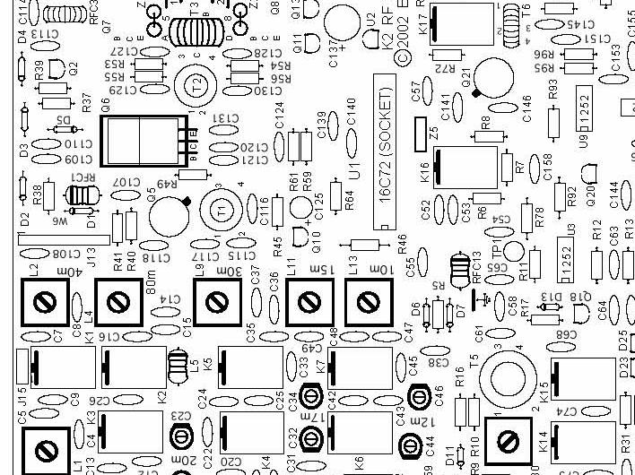
1 Elecraft K Preselector Mod The elecraft K is an excellent transceiver, but in Europe its receiver benefets significantly, especially on 0m, from an external Preselector. Although most Preselectors are designed with an internal T/R relay, theoretically enabling direct insertion between the transceiver and the antenna, there is a problem when running W, especially when running full QSK. The switching time of the internal relay is too slow to follow full QSK. The best way to avoid this problem altogether is to insert the Preselector directly into the transceiver s RX antenna line, thus avoiding entirely the need to switch the Preselector in and out. This feature has emerging as standard on a few of the more recent transceivers (e.g., Yaesu FT-000, Ten-Tec OMNI-VII), but for older rigs, a very simple modification is necessary. The following is a step-by-step description of how to install this mod:. Install RA Phono (inch) jacks on the back panel of the K. These should be installed in the existing holes for XVTR OUT and XVTR IN. If your radio is an older version, you will have to << AREFULLY >> drill two small holes for this. You can identify the position for the holes from current pictures posted on the elecraft web site.. The preselector must be inserted just before the antenna is applied to the first RF stage of the RX. This is easiest accomplished (physically) by interrupting the RX antenna line just BEFORE K (Attenuator Relay) on the main printed circuit board. The antenna signal is normally applied to this relay through.. Unsolder and lift the leg of which is closest to the relay K.. extend this leg vertically upwards, and use this leg to solder the inner conductor of a short piece of RG-U. Trim the braid (shield) of the coax at this point and insulate it with a small piece of heat-shrink tubing.. Solder the inner conductor of a second short piece of RG-U into the hole from which you removed the one leg of. Trim away the braid and insulate as in above.. Solder the cable from to the jack marked OUT. onnect the cable s shield to chassis ground.. Solder the cable from the printed circuit board (K) to the jack marked IN and also connect its shield to chassis ground. Unless your preselector is a passive device and fully bi-directional, you must pay attention to cable connection: onnect the K s OUT to the Preselector s IN onnect the Preselector s OUT to the K s IN NOTE: When there is no external Preselector connected to the K, you must insert a small coaxial jumper (RG- or RG-) between new IN and OUT jacks. Secondary Benefit of this Mod: You may also insert Noise anselors (e.g., S.E.M. QRM Eliminator, TimeWave AN-, etc.) into these jacks to help reduce the effects of heavy QRN. By Rick Westerman, NJ0IP
2 OUT IN
3 RF 00µH D N00 D N00 RF 00µH.0.0 TX VFO T.0 R.K R9 Q0 N000 T BPF (Sh. ) 0. R Xmit Mixer Attenuator -0dB Buffer.0 U9 LT V -.0 R9 0 V- 00pF K R R U0 NE0 R 00 R9 R9.K R9.K.0 R 0 K W R 0 R 0 V XFIL In T D9 S S B 0 R Q N09 RF Preamp db.0.k.0.0 RP, RP: 00K A d a p t e r.0 R0 0K RX VFO V BIAS-XFIL RP RP RP RP RP J9 9 R X X X9 X0 D0 D D D J V Z TUF- Rcv. Mixer RP X R dbm.0 D J MHz Variable-Bandwidth rystal Filter AUXBUS T /DOT-PTT MI AF SSB ontrol V RFDET D9-D: SV9 A EXT AL (NOTE ) V XFIL W XFIL Out NOTE : Remove when SSB Adapter is installed. R0 0 T.0 R.K V RF 00µH Q N09 Post-Mixer Amp. R9.K (NOTE ) R.9K N NOTE : D0 and D were added to improve handling of extremely D0 strong signals (from nearby transmitters). These diodes must be soldered on the back of the P board (see text). D.0 AG R.Ω IF Amp.0 V AL R 0. V AG.0 R R 0.K R 0 R 9 00 R9 0 R U M0 D L.uH 0-0 BFO Buffer/Attenuator N o i s e B l a n k e r I.F. OUT W NB Bypass.0 D9 MV09 nd Xtal Filter.0 TP Q N000 Q PNA X V HI IP D S V XFIL Q J R0 00K G X AUXBUS A 0. X.9MHz BFO Elecraft J 0.0 R 0 Product Det. µh D SV9 00K R00 0 V- R9 00 -db, Z= 0Ω X L V By W. Burdick Rev. E.Swartz F 0. U NE0.0 0 R90 0 NOTE: If Noise Blanker is installed, R and R90 must be removed, and R9 replaced with a jumper. R0.K 00K D SV9 00K K RF Board J Date Sht. //0 of Appendix B Aux. AF PD PD V BFO 00K.0
4
5 9 90 R L 9 Q L J L K K L J D R J 0 J RF Q Q 0 W 9 0 R B R0 E L0 R Z 0m Q 99 K K9 A L9 L P L L B E AUX L9 T T K B RF L T D K0 L 9 9 B Z T K 0 R E Q L K 0 Q Q L0 L R9 L K Q L 0 K U U K (SOKET) L K RF Rev. B L 00 ELERAFT D9 Q Q D Q K K R Q 9 Z D - P R D Q R9 R0 T RF 9 R R TP R AUX V 0 W R R J 0 R T R9 L0 R0 K K K R Z R9 R J9 F R R9 W U R9 RP D9 U9 00K Q0 R9 R90 R X 0 D0 D R D D R X D9 D R R0 R R X9 9 R U R TP D X0 D D0 D D R0 R9 Q 9 J 00K R0 D X 00 R 9 Q R SSB RP 9 T RP 0K 9 R 00K 9 D D W D X J0 P 0 D D U 9 Q9 RF X R TP U X X J RP 0K SPKR X D9 RF U X J R LIFT L R S R0 J J S S D R R X 0 0 R J J R ONTROL BOARD BEVELED ORNER D R NA FRONT PANEL BOARD.M R9 RF Probe Elecraft R P EXT INT Q Q Q D RP K U U0 V Q 0 0 MAX P LM0 OUNTER P U RP.9K Q P 0 RP RP Q INSTALL SOKET FIRST K K 0 U Q R R R9 R0 U PI 9 Q9.K L 9 R0 9 D 9 0 V R 0 U X P Q P Q0 R U V RP RP P J J 0 K U 0 Q K ONTROL Rev. B 00 ELERAFT S S RP 0 DS R E E TIP L.0 R U AND ITS SOKET ARE MOUNTED ON THE OTHER SIDE D D DS R R0 D R D R9 R Q D 9 K Q Q R J R R S S9 S0 S S S 9 Appendix F Parts Placement Drawing, Top S S LINEAR LINEAR D R Q D U RP 0K Z S S S S D J AUDIO LINEAR LINEAR R R R 0 0 R K FP Rev. B 00 ELERAFT
V7 6AG7 DRIVER DRIVER TUNE ALC RECT VFO TANK V3 12SK7 TONE OSC V10 12SK MHz
 V PA* V SK IF AMP 9 V SNGT MIXER MIXER 0 0 V AG 0 0 PA 0 0 RF TUNE RECT PA* *V AND ARE WITH HEATERS IN SERIES OR WITH HEATERS IN PARALLEL.0-. 0 INRAD XTAL FILTER DIODE BALANCED MODULATOR V SNGT CARRIER
Racal RA-117 Receiver Section: Notes, Layout, Tube List Page: 1 Dwg. Rev.: 2013 Jan 17
 Notes Early version retains the 0.- setting on RANGE, along with the accompanying L & C, from the RA-. Later version replaces this with the WIDEBAND Ω setting. Early version takes the socket (SK) off SK00
The AN/ARC-54. Module Circuit Diagrams
 The N/R- Module ircuit iagrams. Tone squelch (selective call). Homing. High requency oscillator HO. Low requency Oscilator LO. Variable I amplifier. R mplifier. Mechanical Tuning Unit. Power mplifier.
SERVICE MANUAL VHF/UHF ALL MODE TRANSCEIVER. i910h
 SERVIE MANUAL VHF/UHF ALL MODE TRANSEIVER i0h INTRODUTION This service manual describes the latest service information for the I-0H VHF/UHF ALL MODE TRANSEIVER at the time of publication. DANGER NEVER
HARTING D-Sub Selection Guide
 HARTING D-Sub Selection Guide People Power Partnership D-Sub Selection Guide D-Sub Device Connectivity HARTING Connectivity & Networks generates solutions throughout the triad of Installation Technology,
CA3089. FM IF System. Description. Features. Ordering Information. Pinout. November 1996
 A0 November FM System Features For FM Amplifier Applications in High-Fidelity, Automotive, and ommunications Receivers Includes: Amplifier, Quadrature Detector, AF Preamplifier, and Specific ircuits for
What You Need to Get Started INSTALLATION GUIDE
 INSTALLATION GUIDE SBS-96F SHIELDED BACKSHELL This guide describes how to assemble and install the SBS-96F shielded backshell with low-voltage SCXI modules, VXI-DAQ modules, or low-voltage TBX terminal
For the electronic measurement of current: DC, AC, pulsed..., with galvanic separation between the primary and the secondary circuit.
 Current Transducer LDSR 0.3-TP/SP1 I P R N = 300 ma For the electronic measurement of current: DC, AC, pulsed..., with galvanic separation between the primary and the secondary circuit. Features Closed
For the electronic measurement of current: DC, AC, pulsed..., with galvanic separation between the primary and the secondary circuit.
 Current Transducer HO-NP series I P N = 4, 6, 12, 15 A Ref: HO 4-NP, HO 6-NP, HO 12-NP, HO 15-NP For the electronic measurement of current: DC, AC, pulsed..., with galvanic separation between the primary
IRGB4056DPbF. n-channel Lead Free Package INSULATED GATE BIPOLAR TRANSISTOR WITH ULTRAFAST SOFT RECOVERY DIODE
 1 www.irf.com 4/11/8 PD - 97188A INSULATED GATE BIPOLAR TRANSISTOR WITH ULTRAFAST SOFT RECOVERY DIODE Features Low V CE (ON) Trench IGBT Technology C Low switching losses Maximum Junction temperature 17
IRGP4263PbF IRGP4263-EPbF
 IRGP3PbF IRGP3-EPbF Insulated Gate Bipolar Transistor V CES = 5V I C = 5A, T C =1 C C G G t SC 5.5µs, T J(max) = 175 C V CE(ON) typ. = 1.7V @ IC = A Applications Industrial Motor Drive Inverters UPS Welding
LM35 Precision Centigrade Temperature Sensors
 LM35 Precision Centigrade Temperature Sensors General Description The LM35 series are precision integrated-circuit temperature sensors, whose output voltage is linearly proportional to the Celsius (Centigrade)
Absolute Maximum Ratings Parameter Max. Units
 PD - 97397A INSULATED GATE BIPOLAR TRANSISTOR WITH ULTRAFAST SOFT RECOVERY DIODE Features Low V CE (ON) Trench IGBT Technology Low switching losses 5 µs short circuit SOA Square RBSOA % of the parts tested
IRGS4062DPbF IRGSL4062DPbF
 INSULATED GATE BIPOLAR TRANSISTOR WITH ULTRAFAST SOFT RECOVERY DIODE Features Low V CE (ON) Trench IGBT Technology Low switching losses Maximum Junction temperature 175 C 5 µs short circuit SOA Square
INFORMATION TECHNOLOGY SYSTEMS SPDs FOR 19 TECHNOLOGY. NET Protector Surge Arrester. Protects switches, HUBs and telecommunication
 Surge Arrester Protects switches, HUBs and telecommunication systems Class D according to EN 0 possible (Gigabit Ethernet) Variably equippable patch panels Units available with plug-in inputs and outputs
CAT Connection Cables. between. RF Amplifier ACOM 600S. and. Transceiver
 CAT Connection Cables between RF Amplifier ACOM 600S and Transceiver Document Version: v1.2 Date: January 20, 2015 Author: Nikolay Nenov Table of Contents ACOM 600S to ELECRAFT K3 RS232 CAT Connection
IRGB8B60KPbF IRGS8B60KPbF IRGSL8B60KPbF C
 INSULATED GATE BIPOLAR TRANSISTOR Features Low VCE (on) Non Punch Through IGBT Technology. 1µs Short Circuit Capability. Square RBSOA. Positive VCE (on) Temperature Coefficient. Lead-Free. Benefits Benchmark
IH5341, IH5352. Dual SPST, Quad SPST CMOS RF/Video Switches. Description. Features. Ordering Information. Applications. Pinouts.
 SEMICONDUCTOR IH, IH2 December Features Description Dual SPST, Quad SPST CMOS RF/Video Switches R DS(ON) < Ω Switch Attenuation Varies Less Than db From DC to 00MHz "OFF" Isolation > 0dB Typical at 0MHz
For the electronic measurement of current: DC, AC, pulsed..., with galvanic separation between the primary and the secondary circuit.
 Current Transducer HO-NP/SP33 series I PN = 8, 15, 25 A Ref: HO 8-NP/SP33, HO 15-NP/SP33, HO 25-NP/SP33 For the electronic measurement of current: DC, AC, pulsed..., with galvanic separation between the
Package Lead Code Identification SINGLE 3 SERIES 3 UNCONNECTED PAIR RING QUAD
 Surface Mount RF Schottky Barrier Diodes Technical Data HSMS-28XX Series Features Surface Mount SOT-2/SOT- 4 Package Low Turn-On Voltage (As Low as 4 V at ma) Low FIT (Failure in Time) Rate* Six-sigma
Final Exam. 55:041 Electronic Circuits. The University of Iowa. Fall 2013.
 Final Exam Name: Max: 130 Points Question 1 In the circuit shown, the op-amp is ideal, except for an input bias current I b = 1 na. Further, R F = 10K, R 1 = 100 Ω and C = 1 μf. The switch is opened at
IRGIB15B60KD1P INSULATED GATE BIPOLAR TRANSISTOR WITH ULTRAFAST SOFT RECOVERY DIODE. n-channel. Absolute Maximum Ratings
 INSULATED GATE BIPOLAR TRANSISTOR WITH ULTRAFAST SOFT RECOVERY DIODE Features Low VCE (on) Non Punch Through IGBT Technology. Low Diode VF. µs Short Circuit Capability. Square RBSOA. Ultrasoft Diode Reverse
IRGP30B60KD-EP V CES = 600V I C = 30A, T C =100 C. t sc > 10µs, T J =150 C. V CE(on) typ. = 1.95V. Absolute Maximum Ratings. Thermal Resistance
 typ. = 1.95V. Absolute Maximum Ratings. Thermal Resistance") INSULATED GATE BIPOLAR TRANSISTOR WITH ULTRAFAST SOFT RECOVERY DIODE Features Low V CE (on) Non Punch Through IGBT Technology. Low Diode V F. 1µs Short Circuit Capability. Square RBSOA. Ultrasoft Diode
INSULATED GATE BIPOLAR TRANSISTOR WITH ULTRAFAST SOFT RECOVERY DIODE Features Low V CE (on) Non Punch Through IGBT Technology. Low Diode V F. 1µs Short Circuit Capability. Square RBSOA. Ultrasoft Diode
Package Lead Code Identification SINGLE 3 SERIES 3 UNCONNECTED PAIR RING QUAD
 Surface Mount RF Schottky Barrier Diodes Technical Data HSMS-28XX Series Features Surface Mount SOT-2/SOT- 4 Package Low Turn-On Voltage (As Low as 4 V at ma) Low FIT (Failure in Time) Rate* Six-sigma
n-channel Standard Pack Orderable part number Form Quantity IRG7PH35UD1MPbF TO-247AD Tube 25 IRG7PH35UD1MPbF
 IRG7PH3UDMPbF INSULATED GATE BIPOLAR TRANSISTOR WITH ULTRA-LOW VF DIODE FOR INDUCTION HEATING AND SOFT SWITCHING APPLICATIONS Features C Low V CE (ON) trench IGBT Technology Low Switching Losses Square
IRGB4B60K IRGS4B60K IRGSL4B60K
 INSULATED GATE BIPOLAR TRANSISTOR PD - 9633A IRGBB6K IRGSB6K IRGSLB6K Features Low VCE (on) Non Punch Through IGBT Technology. 1µs Short Circuit Capability. Square RBSOA. Positive VCE (on) Temperature
Capacitor,Disc. Diode,Silicon P o t e n t i o m e t e r, 1 / 4 " s h a f t Transistor,NPN Transistor,PNP. Re sistor,carbon
 AR36 Ouput and Power Parts Page 1 of 1 Sept. 1975 PARTS LIST * AR-36 * OUTPUT CONTROL MODULE- NUMBER QUANTITY DESCRIPTION VALUE AND RATINGS Cl C C3 Dl thru 4 PI Ql,3 Q Rl R,3,4, 5 R6 R7,13,14 R8 R9,10
Assembly Manual for the Brevard Astronomical Society 16 inch F4.5 Dobsonian Telescope Brevard Astronomical Society P.O. Box 1084 Cocoa, FL 32922
 BAS 16 Telescope Manual Rev 1 Assembly Manual for the Brevard Astronomical Society 16 inch F4.5 Dobsonian Telescope Brevard Astronomical Society P.O. Box 1084 Cocoa, FL 32922 TABLE OF CONTENTS SECTION
IRGB30B60KPbF IRGS30B60KPbF IRGSL30B60KPbF
 PD - 973 INSULATED GATE BIPOLAR TRANSISTOR Features Low VCE (on) Non Punch Through IGBT Technology 1µs Short Circuit Capability Square RBSOA G Positive VCE (on) Temperature Coefficient Maximum Junction
Ceramic Chip Capacitors
 Introduction RGA Multilayer Ceramic Capacitors are constructed by screen printing alternative layers of internal metallic electrodes onto ceramic dielectric materials and firing into a concrete monolithic
Parameter Max. Units V CES Collector-to-Emitter Breakdown Voltage 600 I T C = 25 C Continuous Collector Current
 INSULATED GATE BIPOLAR TRANSISTOR WITH ULTRAFAST SOFT RECOVERY DIODE Features Low V CE (on) Trench IGBT Technology Low Switching Losses 5μs SCSOA Square RBSOA % of The Parts Tested for I LM Positive V
IRGR3B60KD2PbF INSULATED GATE BIPOLAR TRANSISTOR WITH ULTRAFAST SOFT RECOVERY DIODE. n-channel. Absolute Maximum Ratings Parameter Max.
 INSULATED GATE BIPOLAR TRANSISTOR WITH ULTRAFAST SOFT RECOVERY DIODE Features Low VCE (on) Non Punch Through IGBT Technology. Low Diode VF. µs Short Circuit Capability. Square RBSOA. Ultrasoft Diode Reverse
For the electronic measurement of current: DC, AC, pulsed..., with galvanic separation between the primary and the secondary circuit.
 Current Transducer HO-NSM series I PN = 8, 15, 25 A Ref: HO 8-NSM, HO 15-NSM, HO 25-NSM For the electronic measurement of current: DC, AC, pulsed..., with galvanic separation between the primary and the
Observation of neutral hydrogen using FFT spectrometer Argos on a 5m telescope
 Research Collection Report Observation of neutral hydrogen using FFT spectrometer Argos on a 5m telescope Author(s): Monstein, Christian; Meyer, Hansueli Publication Date: 2006 Permanent Link: https://doi.org/10.3929/ethz-a-005228693
Ref: HLSR 16-PW; HLSR 32-PW; HLSR 40-PW-000; HLSR 50-PW-000,
 Digital Current Transducer HLSR-PW series I P N = 16... 50 A Ref: HLSR 16-PW; HLSR 32-PW; HLSR 40-PW-000; HLSR 50-PW-000, Bitstream output from on onboard Sigma Delta modulator. For the electronic measurement
Physical Noise Sources
 AppendixA Physical Noise Sources Contents A.1 Physical Noise Sources................ A-2 A.1.1 Thermal Noise................ A-3 A.1.2 Nyquist s Formula.............. A-5 A.1.3 Shot Noise..................
ECE 6340 Intermediate EM Waves. Fall 2016 Prof. David R. Jackson Dept. of ECE. Notes 15
 ECE 634 Intermediate EM Waves Fall 6 Prof. David R. Jackson Dept. of ECE Notes 5 Attenuation Formula Waveguiding system (WG or TL): S z Waveguiding system Exyz (,, ) = E( xye, ) = E( xye, ) e γz jβz αz
UNIVERSITY OF CALIFORNIA College of Engineering Department of Electrical Engineering and Computer Sciences
 UNIVERSITY OF CALIFORNIA College of Engineering Department of Electrical Engineering and Computer Sciences E. Alon Final EECS 240 Monday, May 19, 2008 SPRING 2008 You should write your results on the exam
LaserTrim Ceramic Chip Capacitor
 DESCRIPTION Laser adjustable monolithic ceramic Rated voltage - 50V Porcelain Capacitors Excellent post-trim Q and ESR No capacitance drift APPLICATIONS Pagers, RF Modems Cellular Communications Remote
Calculation of RF-Interference from Coupled Shielded Hybrid Cables Utilizing Current Probe Measurements
 Calculation of RF-Interference from Coupled Shielded Hybrid Cables Utilizing Current Probe Measurements Dr. Peter Hahne, Ingenieurbüro Dr. Peter Hahne Dr. Martin Aidam, Daimler AG, Andreas Ludwig, Daimler
Low-Sensitivity, Highpass Filter Design with Parasitic Compensation
 Low-Sensitivity, Highpass Filter Design with Parasitic Compensation Introduction This Application Note covers the design of a Sallen-Key highpass biquad. This design gives low component and op amp sensitivities.
Introduction to Electronics and Semiconductor
 Introduction to Electronics and Semiconductor 1 Chapter Objectives To study and understand basic electronics. To study and understand semiconductor principles. 2 Definition Electronics is the branch of
DATA SHEET. BGY115A; BGY115B; BGY115C/P; BGY115D UHF amplifier modules DISCRETE SEMICONDUCTORS May 13
 DISCRETE SEMICONDUCTORS DATA SHEET Supersedes data of May 994 File under Discrete Semiconductors, SC9 996 May 3 FEATURES 6 V nominal supply voltage996 May 3. W output power (BGY5A, BGY5B and BGY5D).4 W
FOCUS: Water Pollkon Prevention and Control
 FOCUS: Water Pollkon Prevention and Control Many industrial processes, such as wastewater treatment, require careful control of ph/orp... By THOMAS H. MARTIN Consulting Chemist Delta Chemicals & Equipment,
20MT120UF "FULL-BRIDGE" IGBT MTP. UltraFast NPT IGBT V CES = 1200V I C = 40A T C = 25 C. 5/ I27124 rev. D 02/03. Features.
 5/ I27124 rev. D 2/3 "FULL-BRIDGE" IGBT MTP 2MT12UF UltraFast NPT IGBT Features UltraFast Non Punch Through (NPT) Technology Positive V CE(ON) Temperature Coefficient 1µs Short Circuit Capability HEXFRED
Power supply, reset circuit, reference voltage and power indicator. Analogue and digital inputs with options for FET outputs
 VR core and power 00v.0 Power supply, reset circuit, reference voltage and power indicator. Port 00v.0 nalogue and digital inputs with options for FET outputs Port 00v.0 igital inputs with optional FET
RF (Radio Frequency) C R 20 Type
 C R 20 Type") RF (Radio Frequency) C R Type (by) PhotoMOS RELAYS.±..69±.8.±..7±.8.±..8±.8 mm inch FEATURES. Low output capacitance between output terminals and low ON-resistance capacitance(c):.pf (typ.) ON resistance(r):
RF (Radio Frequency) C R Type (by) PhotoMOS RELAYS.±..69±.8.±..7±.8.±..8±.8 mm inch FEATURES. Low output capacitance between output terminals and low ON-resistance capacitance(c):.pf (typ.) ON resistance(r):
Radio Frequency Electronics
 Radio Frequency Electronics Preliminaries I Invented Regenerative circuit while an undergraduate (1914) Superheterodyne receiver (1918) Super-regenerative circuit (1922) Frequency modulation (FM) radio
IRGB30B60K IRGS30B60K IRGSL30B60K
 INSULATED GATE BIPOLAR TRANSISTOR Features Low VCE on) Non Punch Through IGBT Technology. µs Short Circuit Capability. Square RBSOA. Positive VCE on) Temperature Coefficient. Maximum Junction Temperature
=25 C Avalanche Energy, single pulse 65 I C. C Soldering Temperature, for 10 seconds 300, (0.063 in. (1.6mm) from case)
 from case)") PD- 94117 IRGP2B12U-E INSULATED GATE BIPOLAR TRANSISTOR Features UltraFast IGBT UltraFast Non Punch Through (NPT) Technology 1 µs Short Circuit capability Square RBSOA Positive V CE (on) Temperature Coefficient
PD- 94117 IRGP2B12U-E INSULATED GATE BIPOLAR TRANSISTOR Features UltraFast IGBT UltraFast Non Punch Through (NPT) Technology 1 µs Short Circuit capability Square RBSOA Positive V CE (on) Temperature Coefficient
2Ω, Quad, SPST, CMOS Analog Switches
 9-73; Rev ; 4/ 2Ω, Quad, SPST, CMOS Analog Switches General Description The // quad analog switches feature.6ω max on-resistance (R ) when operating from a dual ±5V supply. R is matched between channels
N-Channel Enhancement-Mode Vertical DMOS FET
 N-Channel Enhancement-Mode Vertical DMOS FET Features Free from secondary breakdown Low power drive requirement Ease of paralleling Low C ISS and fast switching speeds Excellent thermal stability Integral
IRGB4062DPbF IRGP4062DPbF
 INSULATED GATE BIPOLAR TRANSISTOR WITH ULTRAFAST SOFT RECOVERY DIODE Features Low V CE (ON) Trench IGBT Technology Low switching losses Maximum Junction temperature 75 C 5 µs short circuit SOA Square RBSOA
SGM nA, Non-Unity Gain, Quad Rail-to-Rail Input/Output Operational Amplifier
 PRODUCT DESCRIPTION The SGM8048 operates with a single supply voltage as low as 1.4V, while drawing less than 690nA (TYP) of quiescent current per amplifier. This device is also designed to support rail-to-rail
n-channel Solar Inverter Induction Heating G C E Gate Collector Emitter
 INSULATED GATE BIPOLAR TRANSISTOR WITH ULTRAFAST SOFT RECOVERY DIODE Features C Low V CE (ON) trench IGBT technology Low switching losses Square RBSOA 1% of the parts tested for I LM Positive V CE (ON)
SGM nA, Non-Unity Gain, Dual Rail-to-Rail Input/Output Operational Amplifier
 PRODUCT DESCRIPTION The SGM8046 operates with a single supply voltage as low as 1.4V, while drawing less than 670nA (TYP) of quiescent current per amplifier. This device is also designed to support rail-to-rail
100K SLQ1 OP2 R207. Future option SLQ2 OP2 R307. Future option
 ON N/S E/W NTENN 00 XnF 00 XnF 0 XnF 0 XnF 0 XnF 0 XnF R00 Not Used (*) 0 0nF 0 0nF R0 K 0 nf (*) See "revision level." here below R00 Not Used (*) R0 K 0 nf!!! IMPORTNT!!! 00-0-0 & 00-0-0 Must be determined
Resistivity vs. Temperature of a Superconductor WARNING
 Resistivity vs. Temperature of a Superconductor 1.0 Expected Learning Outcomes Calibrate a transducer (silicon diode) for low-temperature measurements and measure temperatures down to that of boiling liquid
IRGPS40B120UP INSULATED GATE BIPOLAR TRANSISTOR UltraFast IGBT
 PD- 95899A IRGPS4B12UP INSULATED GATE BIPOLAR TRANSISTOR UltraFast IGBT Features Non Punch Through IGBT Technology. 1µs Short Circuit Capability. Square RBSOA. Positive VCE (on) Temperature Coefficient.
PDM-10. Stereo Preamp Mixer CONTENT S: Connections & Operations:...Page 2-5. Specifications:...Page 5. Parts Lists:...Page 5-6. PCBs:...
 SERVICE MANUAL PDM- Stereo Preamp Mixer CONTENT S: Connections & Operations:...Page - Specifications:...Page Parts Lists:...Page - PCBs:...Page - Schematics:...Page - Gemini Sound Products Corp. 0 Clover
D. Gillespie Designs. SCA-35 Capacitor Board. PC Board Assembly. D. Gillespie Designs with EFB TM
 SCA- Capacitor Board with EFB TM PC Board Assembly www.tronola.com Thank you for purchasing our SCA- Capacitor Board with *EFB. We feel it is the single most significant upgrade you can make to your SCA-.
SHM-14 Ultra-Fast, 14-Bit Linear Monolithic Sample-Hold Amplifiers
 INNOVATION and EX C ELL E N C E Ultra-Fast, 1-Bit Linear Monolithic Sample-Hold Amplifiers FEATURES Fast acquisition time: 10ns to ±0.1% 0ns to ±0.0% ns to ±0.01% ±0.001% Nonlinearity 6µV rms output noise
HF SuperPacker Pro 100W Amp Version 3
 HF SuperPacker Pro 00W mp Version Revised 0 0 V Stamps KOOR This is the third generation HF SuperPacker Pro 00W Version home construction project offered by HF Projects. This is a group construction project
A Low-Power Radar Imaging System
 EM Group A Low-Power Radar Imaging System BY GREGORY L. CHARVAT Introduction Through lossy dielectric slab imaging has been receiving much attention recently Current research is very diverse; using various
RX-62N Multi-Breakout Board Options
 RX-N Multi-Breakout Board Options The RX-N Multi-Breakout Board is designed to be a low-cost prototyping tool designed for hand-assembly. Using this document and the related drawings, the board can be
SGM nA, Single Rail-to-Rail I/O Operational Amplifier
 GENERAL DESCRIPTION The SGM8041 is guaranteed to operate with a single supply voltage as low as 1.4V, while drawing less than 710nA (TYP) of quiescent current. This device is also designed to support rail-to-rail
Instruction Manual. DTP Series DC Termination Panels
 Instruction Manual DTP Series DC Termination Panels Rev. B /00 DTP Series manual.p CPI Communications, Inc. Hensley Lane Wylie, TX 00 Phone () 0 WATS (00) FAX () 0 or () General Information The CPI Communications
100K SLQ1 OP2 R207. Future option SLQ2 OP2 R307. Future option
 ON N/S E/W NTENN 00 XnF 00 XnF 0 XnF 0 XnF 0 XnF 0 XnF R00 Not Used (*) 0 0nF 0 0nF R0 K 0 nf (*) See "revision level." here below R00 Not Used (*) R0 K 0 nf!!! IMPORTNT!!! 00-0-0 & 00-0-0 Must be determined
DISCRETE SEMICONDUCTORS DATA SHEET. BLF145 HF power MOS transistor
 DISCRETE SEMICONDUCTORS DATA SHEET September 1992 FEATURES High power gain Low noise figure Good thermal stability Withstands full load mismatch. DESCRIPTION Silicon N-channel enhancement mode vertical
250 P C = 25 C Power Dissipation 160 P C = 100 C Power Dissipation Linear Derating Factor
 PDP TRENCH IGBT PD - 9634 IRG6B33UDPbF Features l Advanced Trench IGBT Technology l Optimized for Sustain and Energy Recovery Circuits in PDP Applications l Low V CE(on) and Energy per Pulse (E PULSE TM
IRG7PH35UDPbF IRG7PH35UD-EP
 INSULATED GATE BIPOLAR TRANSISTOR WITH ULTRAFAST SOFT RECOVERY DIODE Features Low V CE (ON) trench IGBT technology Low switching losses Square RBSOA % of the parts tested for I LM Positive V CE (ON) temperature
EMBEDDED-PROBE FLOATING POTENTIAL CHARGE-DISCHARGE MONITOR
 EMBEDDED-PROBE FLOATING POTENTIAL CHARGE-DISCHARGE MONITOR Keith G. Balmain University of Toronto Department of Electrical and Computer Engineering 10 King s College Rd Toronto, Ontario M5S 3G4, Canada
AUTOMOTIVE CURRENT TRANSDUCER OPEN LOOP TECHNOLOGY HAH1BVW S/08
 AUTOMOTIVE CURRENT TRANSDUCER OPEN LOOP TECHNOLOGY HAH1BVW S/08 Introduction The HAH1BVW family is for the electronic measurement of DC, AC or pulsed currents in high power and low voltage automotive applications
KH600. 1GHz, Differential Input/Output Amplifier. Features. Description. Applications. Typical Application
 KH 1GHz, Differential Input/Output Amplifier www.cadeka.com Features DC - 1GHz bandwidth Fixed 1dB (V/V) gain 1Ω (differential) inputs and outputs -7/-dBc nd/3rd HD at MHz ma output current 9V pp into
Microwave Network Analysis
 Prof. Dr. Mohammad Tariqul Islam titareq@gmail.my tariqul@ukm.edu.my Microwave Network Analysis 1 Text Book D.M. Pozar, Microwave engineering, 3 rd edition, 2005 by John-Wiley & Sons. Fawwaz T. ILABY,
INSTRUCTIONS FOR ASSEMBLY AND OPERATION
 diytube Poseidon Driver for the Dynaco Mark III, IV and DIY INSTRUCTIONS FOR ASSEMBLY AND OPERATION Price $0.00 C Star Ground 0VDC J R6 00K 0VDC K R6 K C.uF G KT: blu/wht & grn/wht V AU 6 a a'' R0 6K,
Digital Current Transducer HO-SW series I P N = A. Ref: HO 100-SW; HO 150-SW; HO 200-SW; HO 250-SW
 Digital Current Transducer HO-SW series I P N = 100... 250 A Ref: HO 100-SW; HO 150-SW; HO 200-SW; HO 250-SW Bitstream output from on onboard Sigma Delta modulator. For the electronic measurement of current:
Electric Field Mapping
 Electric Field Mapping Equipment: mapping board, U-probe, 5 resistive boards, templates, knob adjustable DC voltmeter, 4 long leads, 16 V DC for wall strip, 8 1/2 X 11 sheets of paper Reading: Topics of
LM34 Precision Fahrenheit Temperature Sensors
 1 Precision Fahrenheit Temperature Sensors 1 Features 3 Description 1 Calibrated Directly in Degrees Fahrenheit The series devices are precision integratedcircuit temperature sensors, whose output voltage
Evaluation Board for 8-/10-/12-Bit, Parallel Input, Dual-Channel, Current Output DAC EVAL-AD5428/AD5440/AD5447EB
 Evaluation Board for 8-/0-/-Bit, Parallel Input, Dual-Channel, Current Output DAC EVAL-AD58/AD50/AD5EB FEATURES Operates from dual ± V and 5 V supplies On-board reference and output amplifiers Direct hookup
PERFORMANCE SPECIFICATION SHEET
 INCH-POUND MIL-PRF-22885/77F 2 August 2018 SUPERSEDING MIL-PRF-22885/77E 25 April 2013 PERFORMANCE SPECIFICATION SHEET SWITCHES, PUSH BUTTON, ILLUMINATED, 4-LAMP, 0.75 SQUARE, 7.5 AMPERES, AND LOW LEVEL
Determining Characteristic Impedance and Velocity of Propagation by Measuring the Distributed Capacitance and Inductance of a Line
 Exercise 2-1 Determining Characteristic Impedance and Velocity EXERCISE OBJECTIVES Upon completion of this exercise, you will know how to measure the distributed capacitance and distributed inductance
Characteristic Symbol Value Unit Output Current I out 150 ma
 LBNB ma LOAD SWITH FEATURING OMPLEMENTARY BIPOLAR TRANSISTORS NEW PRODUT General Description LMNB is best suited for applications where the load needs to be turned on and off using control circuits like
Distributing Tomorrow s Technologies For Today s Designs Toll-Free:
 2W, Ultra-High Isolation DIP, Single & DC/DC s Key Features Low Cost 6 Isolation MTBF > 6, Hours Short Circuit Protection Input, and 24 Output,, 1, {, { and {1 Regulated Outputs Low Isolation Capacitance
Resonant Matching Networks
 Chapter 1 Resonant Matching Networks 1.1 Introduction Frequently power from a linear source has to be transferred into a load. If the load impedance may be adjusted, the maximum power theorem states that
This section reviews the basic theory of accuracy enhancement for one-port networks.
 Vector measurements require both magnitude and phase data. Some typical examples are the complex reflection coefficient, the magnitude and phase of the transfer function, and the group delay. The seminar
General Purpose Transistors
 General Purpose Transistors NPN and PNP Silicon These transistors are designed for general purpose amplifier applications. They are housed in the SOT 33/SC which is designed for low power surface mount
Surface Mount RF Schottky Barrier Diodes. Technical Data. GUx. HSMS-281x Series
 Surface Mount RF Schottky Barrier Diodes Technical Data HSMS-28x Series Features Surface Mount Packages Low Flicker Noise Low FIT (Failure in Time) Rate* Six-sigma Quality Level Single, Dual and Quad Versions
DATA SHEET. BGY116D; BGY116E UHF amplifier modules DISCRETE SEMICONDUCTORS May 08
 DISCRETE SEMICONDUCTORS DATA SHEET Supersedes data of April 199 File under Discrete Semiconductors, SC9 199 May FEATURES.5 V nominal supply voltage W output power Easy control of output power by DC voltage.
Feedback Control G 1+FG A
 Introduction to Operational Amplifiers Circuit Functionality So far, only passive circuits (C, L and LC) have been analyzed in terms of the time-domain operator T and the frequency-domain operator A(ω),
Retract. Press down D RG MG LG S. Recess. I-V Converter VNA. Gate ADC. DC Bias. 20 mk. Amplifier. Attenuators. 0.
 a Press down b Retract D RG S c d 2 µm Recess 2 µm.5 µm Supplementary Figure 1 CNT mechanical transfer (a) Schematics showing steps of pressing down and retracting during the transfer of the CNT from the
Electric Field Mapping Lab 2. Precautions
 TS 2-12-12 Electric Field Mapping Lab 2 1 Electric Field Mapping Lab 2 Equipment: mapping board, U-probe, resistive boards, templates, dc voltmeter (431B), 4 long leads, 16 V dc for wall strip Reading:
SGM7227 High Speed USB 2.0 (480Mbps) DPDT Analog Switch
 DPDT Analog Switch") GENERAL DECRIPTION The GM7227 is a high-speed, low-power double-pole/ double-throw (DPDT) analog switch that operates from a single 1.8V to 4.3V power supply. GM7227 is designed for the switching of high-speed
GENERAL DECRIPTION The GM7227 is a high-speed, low-power double-pole/ double-throw (DPDT) analog switch that operates from a single 1.8V to 4.3V power supply. GM7227 is designed for the switching of high-speed
TABLE OF CONTENTS. IC Recorder. Model No. RR-US300E. Colour (S)...Silver Type
...Silver Type") ORDER NO. AD1107003CE IC Recorder Model No. RR-US300E Colour (S)...Silver Type TABLE OF CONTENTS PAGE 1 Warning-------------------------------------------------------------- 2 1.1. Prevention of Electrostatic
ORDER NO. AD1107003CE IC Recorder Model No. RR-US300E Colour (S)...Silver Type TABLE OF CONTENTS PAGE 1 Warning-------------------------------------------------------------- 2 1.1. Prevention of Electrostatic
For the electronic measurement of current: DC, AC, pulsed..., with galvanic separation between the primary and the secondary circuit.
 Current Transducer GO-SMS/SP3 series I P N = 10... 30 A Ref: GO 10-SMS/SP3, GO 20-SMS/SP3, GO 30-SMS/SP3 For the electronic measurement of current: DC, AC, pulsed..., with galvanic separation between the
Parameter Test Conditions Symbol Value Unit Junction ambient on glass fibre printed board (40 x 25 x 1.5) mm 3 plated with 35m Cu
 mm 3 plated with 35m Cu") Silicon NPN Planar RF Transistor BFR96TS Electrostatic sensitive device. Observe precautions for handling. Applications RF amplifier up to GHz range specially for wide band antenna amplifier. Features
Silicon NPN Planar RF Transistor BFR96TS Electrostatic sensitive device. Observe precautions for handling. Applications RF amplifier up to GHz range specially for wide band antenna amplifier. Features
ELECTROMANETIC PULSE PROPAGATION IN A COAXIAL CABLE
 ELECTROMANETIC PULSE PROPAGATION IN A COAXIAL CABLE The mechanical waves on a stretched string are easily generated and observed but not easily studied in quantitative detail. The propagating waves in
CMOS ±5 V/+5 V/+3 V Triple SPDT Switch ADG633
 CMOS ±5 V/+5 V/+3 V Triple SPT Switch AG633 FEATURES ±2 V to ±6 V ual Supply 2 V to 12 ingle Supply Automotive Temperature Range 4 o C to +125 o C
For the electronic measurement of current: DC, AC, pulsed..., with galvanic separation between the primary and the secondary circuit.
 Current Transducer GO-SMS series I P N = 10... 30 A Ref: GO 10-SMS, GO 20-SMS, GO 30-SMS For the electronic measurement of current: DC, AC, pulsed..., with galvanic separation between the primary and the
Series CCR-39S Multi-Throw DC-12 GHz, SP9T & SP10T Latching Coaxial Switch
 COAX SWITCHES Series CCR-39S PART NUMBER CCR-39S DESCRIPTION Commercial Latching Multi-throw, DC-12GHz The CCR-39Sis a broadband, multi-throw, electromechanical coaxial switch designed to switch a microwave