Calculation of RF-Interference from Coupled Shielded Hybrid Cables Utilizing Current Probe Measurements
|
|
|
- Allan Curtis
- 5 years ago
- Views:
Transcription
1 Calculation of RF-Interference from Coupled Shielded Hybrid Cables Utilizing Current Probe Measurements Dr. Peter Hahne, Ingenieurbüro Dr. Peter Hahne Dr. Martin Aidam, Daimler AG, Andreas Ludwig, Daimler AG, Xiaofeng Pan, Daimler AG, Dr. Markus Schick, Altair GmbH
 Simulation of shielded cables in FEKO: Restriction to decoupled inner conductors")

2 Overview EMC of hybrid vehicle electric drive (hybrid system) Hybrid system coaxial power lines Simplified hybrid system: Standard interference device (SID) Simulation of shielded cables in FEKO: Restriction to decoupled inner conductors Solution method for calculation of multiple single-shielded cable systems: Superposition procedure Determination of current spectrum, acting as excitation Measurement SID Comparison of measurement and simulation Utilization of measured currents Summary 2


3 Hybrid system HV-power lines E-Motor Battery Inverter Radio/TV window antennas 3

4 EMC Sketch of Hybrid System Interference into vehicle antennas High voltage battery DC/AC Inverter Electric engine Engine ground strap Antenna amplifier Cause of interference PWM-conversion generates high frequency current and voltage pulses A small fraction of the accompanying electromagnetic fields pass through the cable shields, radiate into the antennas and cause an interference voltage there 4


5 Shielded High Voltage Lines 1 inner conductor 2 Isolator 3 braided shield, 3a foil shield 4 outer insulation The cable properties, especially the braid geometry determines the transfer impedance of the cable. Alternative: measurement Not so simple, unfortunately! Measurement vs Kley formula, optimized, large diameter 5

6 Transfer Impedance According to Various Formulas Transfer impedance Coroplast FLR2GCB2G 16 mm² according to various formulas Frequency [MHz] 6
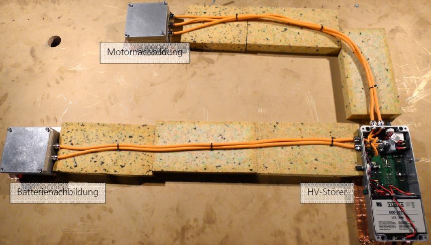
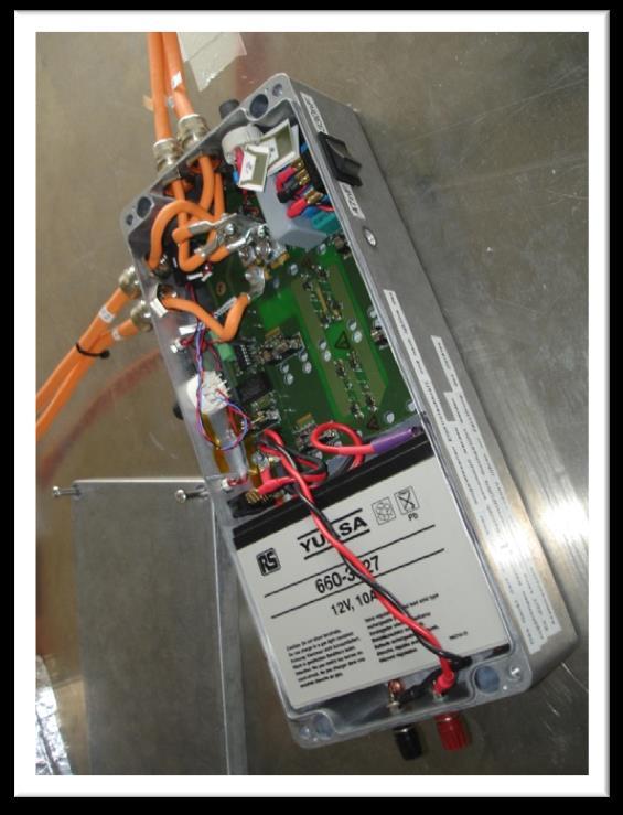
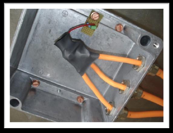
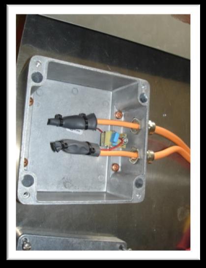
7 Simplified hybrid system: Standard interference device (SID) 7 7


8 Simulation of shielded cables in FEKO Uses the concept of transfer impedance: Coupling of inside and outside by transfer impedance and transfer admittance only Adjustments FEKO Option MOM, radiating. transfer impedance: predefined Kley for braided shields Schekulnoff for massive shields ~ ~ ~ ~ ~ Restrictions für braided shields, option MOM Coaxial cables allowed only It is not enabled to calculate a system of coaxial lines directly, whose inner conductors are electrically coupled 8
:")


9 Indirect FEKO Calculation of the Hybrid System / SID Problem FEKO (Option MOM): Only independent coaxial cables allowed Hybrid system / SID: has coaxial cables with coupled inner conductors One possible solution Excitation of inner conductors by equivalent currents Superposition principle Transfer impedance concept 9
10 Steps towards a Solution I 1. Equivalent current excitation I 1 Z,l I 2 I 1 Z 1 Z 2 Z,l I 2 ~ U 1 U 2 U 1 U 2 State (U(x), I(x)) of conductor is the same for both excitations Voltages result uniquely 2. Superposition principle I 1 Z,l I 2 I 1 Z,l Z,l I
11 Steps towards a Solution II 3. Transfer function, Transfer impedance I 1 U s = I 1 Z s1 ~ U S 4. Superposition principle again I 1 I 2 U s = I 1 Z s1 + I 2 Z s2 ~ U S 11
12 Steps towards a Solution III 5. A shield changes the transfer function, but the linear dependence remains valid I 1 I 2 U s = I 1 Z s1 + I 2 Z s2 ~ U S 6. Application to a multi conductor system I 1 I 2 U s = 4 i=1 I i Z si I 3 I 4 ~ U S Core crosstalk neglected Coupling of originally coupled sources is comprised within complex amplitudes of current excitation 12

13 Summary of Superposition procedure Superposition procedure (SP) 1. Calculation of all transfer functions Z from inner conductor currents at cable ends to a sink by simulation 2. Weighting of transfer functions with complex current spectra at cable ends and summation U s = m i=1 I i Z si 3. Result is a voltage U s (or current, electrical field strength, ) at the sink (antenna, current clamp, field sensor, ) For all sinks the weighting process can be expressed as U = Z I, with vector U (mx1) containing all requested quantities, matrix Z (nxm) containing all transfer functions and vector I (mx1) containing all exciting currents, where m is the number of exciting currents and n is the number of sinks. 13

14 How to Obtain Complex Current Spectra How are complex current spectra obtained? Approach here: Modelling of the inner conductor system in SPICE, simulation in time domain Adjustment of model to measurements of the inner conductor system, i.e. by adding and dimensioning parasitic elements Complex current spectra obtained by simulation in time domain and subsequent Fourier transformation The accuracy of the final result depends linearily of the accuracy of the complex current spectra! 14


, battery lines, coaxial lines")
15 Modelling of the inner conductor system in SPICE Parasitic Elements EC SID Part of equivalent circuit Parasitic elements dominate the frequency spectrum of the lines up from 15 MHz Modelling for higher frequency is troublesome therefore Not shown EC s of: motor imitation (MI), battery imitation (BI), battery lines, coaxial lines EC motor power lines 15
![Voltage [dbv] Voltage [dbv] Comparison of Results of Measurement and Spice Model](/docs-images/88/115850664/images/16-1.jpg "Obtained by FFT measurement data and simulation data Dynamic range of measurement")


16 Voltage [dbv] Voltage [dbv] Comparison of Results of Measurement and Spice Model Obtained by FFT measurement data and simulation data Dynamic range of measurement unsatisfactory Satifactory agreement up to 15 MHz Above 15 MHz no statement possible about validity of SPICE model Motor side modelled better than battery side Voltage spectrum of a line at MI end Voltage spectrum of a line at BI end Simulation Measurement Noise Noise Simulation Measurement Frequency [Hz] Frequency [Hz] 16


17 Measurement SID on Table F-51 SID MI BI F-51 Measurement with 4-channel scope, bandwidth 2.5 GHz Current clamp F-51, 3 positions Antenna R&S HFH2-Z2 150kHz bis 30MHz, distance 1m Antenna R&S HL kHz -1GHz, distance 3m 17

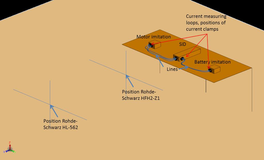
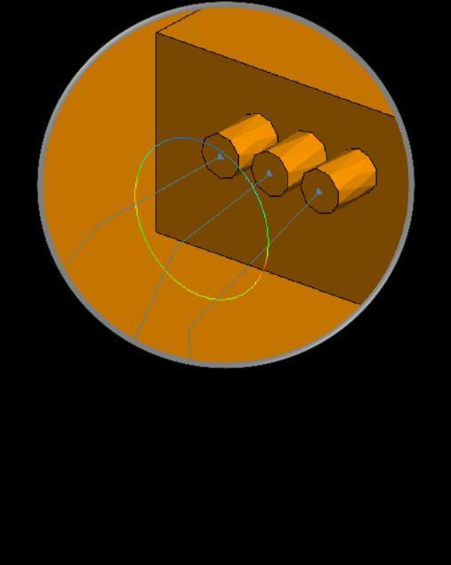
18 Model SID on table 18

19 Results: Total Current Battery Line at SID Total Current Battery Line at SID Simulation Measurement Noise 19

20 Results: Total Current at Motor Imitation Total Current at Motor Imitation Simulation Measurement Noise 20
21 Results: Voltage at Antenna HFH2-Z1 Voltage at Antenna HFH2-Z1 Measurement Simulation 21
 No general rule known for the applicability of the various formulas (Kley, Vance, Tyni, Demoulin) for the")
22 Summary up to here + Superposition procedure (SP) works fine + Acceptable results up to 15 MHz Inaccurate results up from15 MHz Reason: a) SPICE modelling of inner conductor system to obtain current spectra troublesome due to parasitic elements -> fair approximation only up to 15MHz b) No general rule known for the applicability of the various formulas (Kley, Vance, Tyni, Demoulin) for the prediction of shield transfer impedance 22
, a special kind of Z, couples m currents I to m sheath currents J measureable outside the cable. Coefficients T ij, Z ij are determined by simulation.")
23 Utilizing Current Probe Measurements Z (nxm) couples m currents I at inner conductor line ends to n thereof linear dependent quantities U (e.g. U 3 ). T (mxm), a special kind of Z, couples m currents I to m sheath currents J measureable outside the cable. Coefficients T ij, Z ij are determined by simulation. Calculation of currents J i J 1 = T 11 I 1 + T 12 I 2 J 2 = T 21 I 1 + T 22 I 2 Can be written as J = T I I = T 1 J Excitation I can be calculated from measured sheath currents J Current clamp i measures J i J 1 J 2 I 1 I 2 Calculation of voltage U i U i = Z i1 I 1 + Z i2 I 2 = Z i1 Z i2 I 1 I2 = Z i T 1 J Z i : i-th row of Z = Z i I U i ~ Voltage U i (and any other linear dependent quantity) can be calculated from measured sheath currents J 23

24 Shields don t matter A transfer function can be separated into a shield dependent part and a part depending on all other factors (mainly geometrical ones). For a transfer function Z ij acting on current I i this can be written as Z ij = Z ij Z t,i For all transfer functions Z this can be expressed by a diagonal matrix D t, containing the transfer impedances Z t,i at the m cable ends associated to the m exciting currents I i. Z = Z D t Analog for matrix T, that couples the measured currents to the exciting currents T ij = T ij Z t,i T = T D t T 1 = D t 1 T 1 The dependent quantities U are calculated by U = Z I = Z T 1 J = Z 1 D t D t T 1 J = Z T 1 J This shows: The calculation of dependent quantities U by measured sheath currents J does not depend on the transfer impedance of the shields. 24
 Transfer impedance (obtained by formula) Geometry of SID setup Decoupled inner conductors, computational requirement (accomplished by")
25 Summary Intention: EMC simulation of hybrid vehicle electric drive system Simplified model: SID and battery/motor imitations Inner and outer system: coupled by transfer impedance of cables Simulation needs: Sources (obtained by measurement + SPICE modelling) Transfer impedance (obtained by formula) Geometry of SID setup Decoupled inner conductors, computational requirement (accomplished by superposition procedure) Comparison with measurement: Results ok up to 15 MHz, inaccurate above. Reason: Inaccurate SPICE modeling of sources due to parasitic elements Remedy: Calculate source currents by measured sheath currents using the superposition procedure Replaces SPICE modelling Transfer impedances do not contribute Not measured yet 25
SPICE MODELS FOR RADIATED AND CONDUCTED SUSCEPTIBILITY ANALYSES OF MULTICONDUCTOR SHIELDED CABLES
 Progress In Electromagnetics Research, PIER 103, 241 257, 2010 SPICE MODELS FOR RADIATED AND CONDUCTED SUSCEPTIBILITY ANALYSES OF MULTICONDUCTOR SHIELDED CABLES H. Xie, J. Wang, R. Fan, and Y. Liu Department
user's manual nx frequency converters resolver option board opt-bc
 user's manual nx frequency converters resolver option board opt-bc INDEX Document code: ud01039d Date: 18.2.2011 1. Resolver option board OPT-BC... 3 1.1 Resolver basics... 3 1.2 Resolver board features...
A CAD tool for the electromagnetic modeling of braided wire shields
 A CAD tool for the electromagnetic modeling of braided wire shields Ruben Otin and Roger Isanta CIMNE - International Center For Numerical Methods in Engineering Parque Mediterráneo de la Tecnología (PMT)
Electromagnetics in COMSOL Multiphysics is extended by add-on Modules
 AC/DC Module Electromagnetics in COMSOL Multiphysics is extended by add-on Modules 1) Start Here 2) Add Modules based upon your needs 3) Additional Modules extend the physics you can address 4) Interface
ELECTROMANETIC PULSE PROPAGATION IN A COAXIAL CABLE
 ELECTROMANETIC PULSE PROPAGATION IN A COAXIAL CABLE The mechanical waves on a stretched string are easily generated and observed but not easily studied in quantitative detail. The propagating waves in
Determining Characteristic Impedance and Velocity of Propagation by Measuring the Distributed Capacitance and Inductance of a Line
 Exercise 2-1 Determining Characteristic Impedance and Velocity EXERCISE OBJECTIVES Upon completion of this exercise, you will know how to measure the distributed capacitance and distributed inductance
Graduate Diploma in Engineering Circuits and waves
 9210-112 Graduate Diploma in Engineering Circuits and waves You should have the following for this examination one answer book non-programmable calculator pen, pencil, ruler No additional data is attached
Ring Cores General Information
 Ring s General Information Our product line includes a wide range of ring cores with finely graded diameters ranging from 2,5 to 200 mm (see overview of available types). Other core heights can be supplied
Homework Assignment 09
 Homework Assignment 09 Question 1 (Short Takes) Two points each unless otherwise indicated. 1. What is the 3-dB bandwidth of the amplifier shown below if r π = 2.5K, r o = 100K, g m = 40 ms, and C L =
Understanding EMC Basics
 1of 7 series Webinar #1 of 3, February 27, 2013 EM field theory, and 3 types of EM analysis Webinar Sponsored by: EurIng CEng, FIET, Senior MIEEE, ACGI AR provides EMC solutions with our high power RF/Microwave
NR/RR. Set No. 2 CODE NO: NR/RR210204
 Set No. 2 II B.Tech I Semester Examinations,May 2011 ELECTROMAGNETIC FIELDS Electrical And Electronics Engineering Time: 3 hours Max Marks: 80 Answer any FIVE Questions All Questions carry equal marks
Electromagnetic Modelling Process to Improve Cabling of Power Electronic Structures
 Electromagnetic Modelling Process to Improve Cabling of Power Electronic Structures J. Aimé (1, 2), E. Clavel (1), J. Roudet (1), G. Meunier (1), P. Loizelet (2) (1) G2Elab, Electrical Engineering laboratory
Transient Response of Transmission Lines and TDR/TDT
 Transient Response of Transmission Lines and TDR/TDT Tzong-Lin Wu, Ph.D. EMC Lab. Department of Electrical Engineering National Sun Yat-sen University Outlines Why do we learn the transient response of
and Ee = E ; 0 they are separated by a dielectric material having u = io-s S/m, µ, = µ, 0
 602 CHAPTER 11 TRANSMISSION LINES 11.10 Two identical pulses each of magnitude 12 V and width 2 µs are incident at t = 0 on a lossless transmission line of length 400 m terminated with a load. If the two
Progress In Electromagnetics Research, Vol. 106, 1 16, 2010
 Progress In Electromagnetics Research, Vol. 106, 1 16, 2010 TRANSIENT RESPONSES OF COAXIAL CABLES IN AN ELECTRICALLY LARGE CABIN WITH SLOTS AND WINDOWNS ILLUMINATED BY AN ELECTROMAG- NETIC PULSE J. Wang
PRACTICE NO. PD-AP-1309 PREFERRED PAGE 1 OF 5 RELIABILITY PRACTICES ANALYSIS OF RADIATED EMI FROM ESD EVENTS CAUSED BY SPACE CHARGING
 PREFERRED PAGE 1 OF 5 RELIABILITY PRACTICES ANALYSIS OF RADIATED EMI FROM ESD EVENTS Practice: Modeling is utilized for the analysis of conducted and radiated electromagnetic interference (EMI) caused
Homework Assignment 08
 Homework Assignment 08 Question 1 (Short Takes) Two points each unless otherwise indicated. 1. Give one phrase/sentence that describes the primary advantage of an active load. Answer: Large effective resistance
FREQUENTLY ASKED QUESTIONS RF & MICROWAVE PRODUCTS
 FREQUENTLY ASKED QUESTIONS RF & MICROWAVE PRODUCTS WHAT IS RF? RF stands for Radio Frequency, which has a frequency range of 30KHz - 300GHz. RF capacitors help tune antenna to the correct frequency. The
EM Simulations using the PEEC Method - Case Studies in Power Electronics
 EM Simulations using the PEEC Method - Case Studies in Power Electronics Andreas Müsing Swiss Federal Institute of Technology (ETH) Zürich Power Electronic Systems www.pes.ee.ethz.ch 1 Outline Motivation:
Chapter 24 Capacitance and Dielectrics
 Chapter 24 Capacitance and Dielectrics 1 Capacitors and Capacitance A capacitor is a device that stores electric potential energy and electric charge. The simplest construction of a capacitor is two parallel
INVERSION OF TRANSIENT EDDY-CURRENT SIGNALS FOR THE DETERMINATION OF CONDUCTING PLATE PARAMETERS
 INVERSION OF TRANSIENT EDDY-CURRENT SIGNALS FOR THE DETERMINATION OF CONDUCTING PLATE PARAMETERS M. J. Johnson and J. R. Bowler Department Of Physics University Of Surrey Guildford Surrey GU25XH United
Core Technology Group Application Note 3 AN-3
 Measuring Capacitor Impedance and ESR. John F. Iannuzzi Introduction In power system design, capacitors are used extensively for improving noise rejection, lowering power system impedance and power supply
Numerical Field Simulation for EMC
 Numerical Field Simulation for EMC Dr. Franz Schlagenhaufer IEEE EMC-S Distinguished Lecturer 2007/2008 franz-s@watri.org.au http://www.watri.org.au The University of Western Australia Western Australian
Simulation of cable coupling. David W. P. Thomas
 Simulation of cable coupling David W. P. Thomas November, 2008 Abstract This is the first report on the study of cable coupling. The work to date has involved developing models of the cable coupling phenomenon.
Capacitive Pick-Up Type DB 040
 Capacitive Pick-Up Type DB 040 Tel: (609) 924-3011 Fax (609) 924-3018 www.princetonscientific.com Email: info@princetonscientific.com CAPACITIVE PICK-UP PROBE TYPE DB 040 Application: The capacitive pick-up
Non-Sinusoidal Waves on (Mostly Lossless)Transmission Lines
Transmission Lines") Non-Sinusoidal Waves on (Mostly Lossless)Transmission Lines Don Estreich Salazar 21C Adjunct Professor Engineering Science October 212 https://www.iol.unh.edu/services/testing/sas/tools.php 1 Outline of
Non-Sinusoidal Waves on (Mostly Lossless)Transmission Lines Don Estreich Salazar 21C Adjunct Professor Engineering Science October 212 https://www.iol.unh.edu/services/testing/sas/tools.php 1 Outline of
ECE-343 Test 1: Feb 10, :00-8:00pm, Closed Book. Name : SOLUTION
 ECE-343 Test : Feb 0, 00 6:00-8:00pm, Closed Book Name : SOLUTION C Depl = C J0 + V R /V o ) m C Diff = τ F g m ω T = g m C µ + C π ω T = g m I / D C GD + C or V OV GS b = τ i τ i = R i C i ω H b Z = Z
CHAPTER 4 ANALYSIS AND DESIGN OF THE DUAL INVERTED-F ANTENNA
 CHAPTER 4 ANALYSIS AND DESIGN OF THE DUAL INVERTED-F ANTENNA 4.1. Introduction The previous chapter presented the Inverted-F Antenna (IFA) and its variations as antenna designs suitable for use in hand-held
ECE 497 JS Lecture - 13 Projects
 ECE 497 JS Lecture - 13 Projects Spring 2004 Jose E. Schutt-Aine Electrical & Computer Engineering University of Illinois jose@emlab.uiuc.edu 1 ECE 497 JS - Projects All projects should be accompanied
Todd H. Hubing. Michelin Professor of Vehicle Electronics Clemson University
 Todd H. Hubing Michelin Professor of Vehicle Electronics Clemson University August 4, 2014 IEEE EMC Symposium Fundamentals Workshop 2 August 4, 2014 IEEE EMC Symposium Fundamentals Workshop 3 August 4,
Physical Noise Sources
 AppendixA Physical Noise Sources Contents A.1 Physical Noise Sources................ A-2 A.1.1 Thermal Noise................ A-3 A.1.2 Nyquist s Formula.............. A-5 A.1.3 Shot Noise..................
AC Circuits. The Capacitor
 The Capacitor Two conductors in close proximity (and electrically isolated from one another) form a capacitor. An electric field is produced by charge differences between the conductors. The capacitance
Contents. Transmission Lines The Smith Chart Vector Network Analyser (VNA) ü structure ü calibration ü operation. Measurements
 ü structure ü calibration ü operation. Measurements") Contents Transmission Lines The Smith Chart Vector Network Analyser (VNA) ü structure ü calibration ü operation Measurements Göran Jönsson, EIT 2015-04-27 Vector Network Analysis 2 Waves on Lines If the
Contents Transmission Lines The Smith Chart Vector Network Analyser (VNA) ü structure ü calibration ü operation Measurements Göran Jönsson, EIT 2015-04-27 Vector Network Analysis 2 Waves on Lines If the
User Manual VX4750 Function Generator Module
 User Manual VX4750 Function Generator Module 070-9151-05 This document applies for firmware version 2.60 and above. Copyright Tektronix, Inc. All rights reserved. Tektronix products are covered by U.S.
ECE357H1S ELECTROMAGNETIC FIELDS TERM TEST March 2016, 18:00 19:00. Examiner: Prof. Sean V. Hum
 UNIVERSITY OF TORONTO FACULTY OF APPLIED SCIENCE AND ENGINEERING The Edward S. Rogers Sr. Department of Electrical and Computer Engineering ECE357H1S ELECTROMAGNETIC FIELDS TERM TEST 2 21 March 2016, 18:00
MAS.836 PROBLEM SET THREE
 MAS.836 PROBLEM SET THREE FSR, Strain Gauge, and Piezo Circuits: The purpose of this problem set is to familiarize yourself with the most common forms of pressure and force measurement. The circuits you
Demystifying Transmission Lines: What are They? Why are They Useful?
 Demystifying Transmission Lines: What are They? Why are They Useful? Purpose of This Note This application note discusses theory and practice of transmission lines. It outlines the necessity of transmission
Partial discharge (PD) is well established as a diagnostic
 is well established as a diagnostic") F E A T U R E A R T I C L E Application of Maxwell Solvers to PD Propagation Part I: Concepts and Codes Key Words: Partial discharge propagation, electromagnetic field analysis, Maxwell solvers, boundary
F E A T U R E A R T I C L E Application of Maxwell Solvers to PD Propagation Part I: Concepts and Codes Key Words: Partial discharge propagation, electromagnetic field analysis, Maxwell solvers, boundary
ECE414/514 Electronics Packaging Spring 2012 Lecture 6 Electrical D: Transmission lines (Crosstalk) Lecture topics
 Lecture topics") ECE414/514 Electronics Packaging Spring 2012 Lecture 6 Electrical D: Transmission lines (Crosstalk) James E. Morris Dept of Electrical & Computer Engineering Portland State University 1 Lecture topics
ECE414/514 Electronics Packaging Spring 2012 Lecture 6 Electrical D: Transmission lines (Crosstalk) James E. Morris Dept of Electrical & Computer Engineering Portland State University 1 Lecture topics
Electromagnetic Compatibility!
 Electromagnetic Compatibility! Space System Design, MAE 342, Princeton University! Robert Stengel!! Problems, Analysis, and Testing!! Specifications!! Fundamentals!! Systems Approach!! Categories!! Spacecraft
Provläsningsexemplar / Preview TECHNICAL REPORT INTERNATIONAL SPECIAL COMMITTEE ON RADIO INTERFERENCE
 TECHNICAL REPORT CISPR 16-4-1 2003 AMENDMENT 1 2004-12 INTERNATIONAL SPECIAL COMMITTEE ON RADIO INTERFERENCE Amendment 1 Specification for radio disturbance and immunity measuring apparatus and methods
NAME SID EE42/100 Spring 2013 Final Exam 1
 NAME SID EE42/100 Spring 2013 Final Exam 1 1. Short answer questions a. There are approximately 36x10 50 nucleons (protons and neutrons) in the earth. If we wanted to give each one a unique n-bit address,
Conventional Paper I-2010
 Conventional Paper I-010 1. (a) Sketch the covalent bonding of Si atoms in a intrinsic Si crystal Illustrate with sketches the formation of bonding in presence of donor and acceptor atoms. Sketch the energy
EMBEDDED-PROBE FLOATING POTENTIAL CHARGE-DISCHARGE MONITOR
 EMBEDDED-PROBE FLOATING POTENTIAL CHARGE-DISCHARGE MONITOR Keith G. Balmain University of Toronto Department of Electrical and Computer Engineering 10 King s College Rd Toronto, Ontario M5S 3G4, Canada
Technical specification FLUXUS F502TE
 Technical specification FLUXUS F502TE Permanently installed and non-invasive ultrasonic flowmeter for the measurement of thermal energy and volumetric flow rate Precise and intelligent energy measuring
Bridge Measurement 2.1 INTRODUCTION Advantages of Bridge Circuit
 2 Bridge Measurement 2.1 INTRODUCTION Bridges are often used for the precision measurement of component values, like resistance, inductance, capacitance, etc. The simplest form of a bridge circuit consists
The Co-Conical Field Generation System A 40 GHz Antenna Test Cell
 A 40 GHz Antenna Test Cell David R. Novotny and Robert T. Johnk RF Technology Division 325 Broadway Boulder, Colorado 80303-3328 http://www.boulder.nist.gov/div813/rffields/emc_emi/co_con.html An Effort
Technique for the electric and magnetic parameter measurement of powdered materials
 Computational Methods and Experimental Measurements XIV 41 Technique for the electric and magnetic parameter measurement of powdered materials R. Kubacki,. Nowosielski & R. Przesmycki Faculty of Electronics,
Basic Electronics. Introductory Lecture Course for. Technology and Instrumentation in Particle Physics Chicago, Illinois June 9-14, 2011
 Basic Electronics Introductory Lecture Course for Technology and Instrumentation in Particle Physics 2011 Chicago, Illinois June 9-14, 2011 Presented By Gary Drake Argonne National Laboratory Session 2
AUTOMOTIVE CURRENT TRANSDUCER OPEN LOOP TECHNOLOGY HC6H 400-S/SP1
 AUTOMOTIVE CURRENT TRANSDUCER OPEN LOOP TECHNOLOGY HC6H 400-S/SP1 Picture of product with pencil Introduction The HC6H family is for the electronic measurement of DC, AC or pulsed currents in high power
Possibilities of Using COMSOL Software in Physics
 ALEKSANDRAS STULGINSKIS UNIVERSITY Possibilities of Using COMSOL Software in Physics Jolita Sakaliūnienė 1 Overview Requirement of study quality Student motivation COMSOL software Composition of COMSOL
STUDY OF LOSS EFFECT OF TRANSMISSION LINES AND VALIDITY OF A SPICE MODEL IN ELECTROMAG- NETIC TOPOLOGY
 Progress In Electromagnetics Research, PIER 90, 89 103, 2009 STUDY OF LOSS EFFECT OF TRANSMISSION LINES AND VALIDITY OF A SPICE MODEL IN ELECTROMAG- NETIC TOPOLOGY H. Xie, J. Wang, R. Fan, andy. Liu Department
EE Branch GATE Paper 2010
 Q.1 Q.25 carry one mark each 1. The value of the quantity P, where, is equal to 0 1 e 1/e 2. Divergence of the three-dimensional radial vector field is 3 1/r 3. The period of the signal x(t) = 8 is 0.4
System design of 60K Stirling-type co-axial pulse tube coolers for HTS RF filters
 System design of 60K Stirling-type co-axial pulse tube coolers for HTS RF filters Y. L. Ju, K. Yuan, Y. K. Hou, W. Jing, J. T. Liang and Y. Zhou Cryogenic Laboratory, Technical Institute of Physics and
ELECTRICAL AND THERMAL DESIGN OF UMBILICAL CABLE
 ELECTRICAL AND THERMAL DESIGN OF UMBILICAL CABLE Derek SHACKLETON, Oceaneering Multiflex UK, (Scotland), DShackleton@oceaneering.com Luciana ABIB, Marine Production Systems do Brasil, (Brazil), LAbib@oceaneering.com
Effects from the Thin Metallic Substrate Sandwiched in Planar Multilayer Microstrip Lines
 Progress In Electromagnetics Research Symposium 2006, Cambridge, USA, March 26-29 115 Effects from the Thin Metallic Substrate Sandwiched in Planar Multilayer Microstrip Lines L. Zhang and J. M. Song Iowa
INSTRUMENTAL ENGINEERING
 INSTRUMENTAL ENGINEERING Subject Code: IN Course Structure Sections/Units Section A Unit 1 Unit 2 Unit 3 Unit 4 Unit 5 Unit 6 Section B Section C Section D Section E Section F Section G Section H Section
A SIMPLIFIED RELATIONSHIP BETWEEN SURFACE TRANSFER IMPEDANCE AND MODE STIRRED CHAMBER SHIELDING EFFECTIVENESS OF CABLES AND CONNECTORS
 Record of the EMC Europe 22 International Symposium on Electromagnetic Compatibility, Sorrento, Italy, September 22, pp 441-4461 A SIMPLIFIED RELATIONSHIP BETWEEN SURFACE TRANSFER IMPEDANCE AND MODE STIRRED
4.4 Microstrip dipole
 4.4 Microstrip dipole Basic theory Microstrip antennas are frequently used in today's wireless communication systems. Thanks to their low profile, they can be mounted to the walls of buildings, to the
Output intensity measurement on a diagnostic ultrasound machine using a calibrated thermoacoustic sensor
 Institute of Physics Publishing Journal of Physics: Conference Series 1 (2004) 140 145 doi:10.1088/1742-6596/1/1/032 Advanced Metrology for Ultrasound in Medicine Output intensity measurement on a diagnostic
Numerical and Experimental Radar Cross Section Analysis of the Quadrocopter DJI Phantom 2
 Numerical and Experimental Radar Cross Section Analysis of the Quadrocopter DJI Phantom 2 Arne Schröder 1, Matthias Renker 2, Uwe Aulenbacher 3, Axel Murk 1, Urs Böniger 2, Roland Oechslin 2, and Peter
Chapter 30. Inductance
 Chapter 30 Inductance Self Inductance When a time dependent current passes through a coil, a changing magnetic flux is produced inside the coil and this in turn induces an emf in that same coil. This induced
Adaptives Energy Harvesting für Condition Monitoring Anwendungen im maritimen Umfeld
 Adaptives Energy Harvesting für Condition Monitoring Anwendungen im maritimen Umfeld Daniel Hoffmann 1, Alexander Willmann 1, Thorsten Hehn 1, Yiannos Manoli 1,2 1 Hahn-Schickard, Wilhelm-Schickard-Str.
Observation of neutral hydrogen using FFT spectrometer Argos on a 5m telescope
 Research Collection Report Observation of neutral hydrogen using FFT spectrometer Argos on a 5m telescope Author(s): Monstein, Christian; Meyer, Hansueli Publication Date: 2006 Permanent Link: https://doi.org/10.3929/ethz-a-005228693
BTE5000 / PTE5000 / PTU5000 Series Precision differential pressure transmitters
 FEATURES 5 mbar to 0 bar, 0. to 50 psi differential pressure...6 or...0 ma Precision temperature compensated and calibrated Rugged aluminium housing Female /8" BSP and /8" NPT fittings MEDIA COMPATIBILITY
Chapter 24 Capacitance and Dielectrics
 Chapter 24 Capacitance and Dielectrics 1 Capacitors and Capacitance A capacitor is a device that stores electric potential energy and electric charge. The simplest construction of a capacitor is two parallel
EMC 2016: International Symposium on Electromagnetic Compatibility and EMC Europe
 EMC 2016: International Symposium on Electromagnetic Compatibility and EMC Europe September 09 th, 2016, Wroclaw Dr. Jean-Roger K. Kuvedu-Libla Delphi Electronics & Safety Bascharage, Luxembourg roger.kuvedu.libla@delphi.com
Problem 2: 25 points The space between the conductors of a long coaxial cable used to transmit television signals has an inner radius r 1 =0:15 mm and
 Physics 272. Practice Final Exam On the nal exam there will be 8 problems. The nal exam is Thursday May 12th, 9:45-11:45 a.m. in WAT 112 Problem 1: 25 points A sphere has a volume charge density (r) =
Design Engineering MEng EXAMINATIONS 2016
 IMPERIAL COLLEGE LONDON Design Engineering MEng EXAMINATIONS 2016 For Internal Students of the Imperial College of Science, Technology and Medicine This paper is also taken for the relevant examination
Homework 4 Part One Due 14 October at 6:00 pm
 1. Coaxial Cable Electric Field Homework 4 Part One Due 14 October at 6:00 pm r a. Using the solution to problem 2 of HW3, write the electric field Er () of the CATV coaxial cable in full vector form (with
Modeling of Overhead Power Lines for Broadband PLC Applications.
 Modeling of Overhead Power Lines for Broadband PLC Applications. T. A. Papadopoulos, G. K. Papagiannis, D. P. Labridis Power Systems Laboratory Dept. of Electrical & Computer Engineering Aristotle University
Contents. Transmission Lines The Smith Chart Vector Network Analyser (VNA) ü structure ü calibration ü operation. Measurements
 ü structure ü calibration ü operation. Measurements") Contents Transmission Lines The Smith Chart Vector Network Analyser (VNA) ü structure ü calibration ü operation Measurements Göran Jönsson, EIT 2017-05-12 Vector Network Analysis 2 Waves on Lines If the
Contents Transmission Lines The Smith Chart Vector Network Analyser (VNA) ü structure ü calibration ü operation Measurements Göran Jönsson, EIT 2017-05-12 Vector Network Analysis 2 Waves on Lines If the
Status Report: Charge Cloud Explosion
 Status Report: Charge Cloud Explosion J. Becker, D. Eckstein, R. Klanner, G. Steinbrück University of Hamburg Detector laboratory 1. Introduction and Motivation. Set-up available for measurement 3. Measurements
Effects of Noise in Time Dependent RWM Feedback Simulations
 Effects of Noise in Time Dependent RWM Feedback Simulations O. Katsuro-Hopkins, J. Bialek, G. Navratil (Department of Applied Physics and Applied Mathematics, Columbia University, New York, NY USA) Building
MCE603: Interfacing and Control of Mechatronic Systems. Chapter 1: Impedance Analysis for Electromechanical Interfacing
 MCE63: Interfacing and Control of Mechatronic Systems Chapter 1: Impedance Analysis for Electromechanical Interfacing Part B: Input and Output Impedance Cleveland State University Mechanical Engineering
An Optimised High Current Impulse Source
 An Optimised High Current Impulse Source S. Kempen, D. Peier Institute of High Voltage Engineering, University of Dortmund, Germany Abstract Starting from a predefined 8/0 µs impulse current, the design
Wave Phenomena Physics 15c. Lecture 8 LC Transmission Line Wave Reflection
 Wave Phenomena Physics 15c Lecture 8 LC Transmission Line Wave Reflection Midterm Exam #1 Midterm #1 has been graded Class average = 80.4 Standard deviation = 14.6 Your exam will be returned in the section
Accurate Fourier Analysis for Circuit Simulators
 Accurate Fourier Analysis for Circuit Simulators Kenneth S. Kundert Cadence Design Systems (Based on Presentation to CICC 94) Abstract A new approach to Fourier analysis within the context of circuit simulation
(1) The open and short circuit required for the Z and Y parameters cannot usually be
 The open and short circuit required for the Z and Y parameters cannot usually be") ECE 580 Network Theory Scattering Matrix 76 The Scattering Matrix Motivation for introducing the SM: () The open and short circuit required for the Z and Y parameters cannot usually be implemented in actual
ECE 580 Network Theory Scattering Matrix 76 The Scattering Matrix Motivation for introducing the SM: () The open and short circuit required for the Z and Y parameters cannot usually be implemented in actual
Experiment 1: Laboratory Experiments on Ferroelectricity
 Experiment 1: Laboratory Experiments on Ferroelectricity 1. Task: 1. Set up a Sawyer-Tower circuit to measure ferroelectric hysteresis curves. 2. Check the D(E) curves for a capacitor, a resistor and an
Hong Young Chang Department of Physics, Korea Advanced Institute of Science and Technology (KAIST), Republic of Korea
, Republic of Korea") Hong Young Chang Department of Physics, Korea Advanced Institute of Science and Technology (KAIST), Republic of Korea Index 1. Introduction 2. Some plasma sources 3. Related issues 4. Summary -2 Why is
Hong Young Chang Department of Physics, Korea Advanced Institute of Science and Technology (KAIST), Republic of Korea Index 1. Introduction 2. Some plasma sources 3. Related issues 4. Summary -2 Why is
farads or 10 µf. The letter indicates the part tolerance (how close should the actual value be to the marking).
.") p1 EE1050/60 Capacitors Lab University of Utah Electrical Engineering Department EE1050/1060 Capacitors A. Stolp, 10/4/99 rev 3/17/01 Objectives 1.) Observe charging and discharging of a capacitor. 2.)
p1 EE1050/60 Capacitors Lab University of Utah Electrical Engineering Department EE1050/1060 Capacitors A. Stolp, 10/4/99 rev 3/17/01 Objectives 1.) Observe charging and discharging of a capacitor. 2.)
ANTENNAS and MICROWAVES ENGINEERING (650427)
") Philadelphia University Faculty of Engineering Communication and Electronics Engineering ANTENNAS and MICROWAVES ENGINEERING (65427) Part 2 Dr. Omar R Daoud 1 General Considerations It is a two-port network
Philadelphia University Faculty of Engineering Communication and Electronics Engineering ANTENNAS and MICROWAVES ENGINEERING (65427) Part 2 Dr. Omar R Daoud 1 General Considerations It is a two-port network
Lecture 12. Microwave Networks and Scattering Parameters
 Lecture Microwave Networs and cattering Parameters Optional Reading: teer ection 6.3 to 6.6 Pozar ection 4.3 ElecEng4FJ4 LECTURE : MICROWAE NETWORK AND -PARAMETER Microwave Networs: oltages and Currents
LM34 Precision Fahrenheit Temperature Sensors
 1 Precision Fahrenheit Temperature Sensors 1 Features 3 Description 1 Calibrated Directly in Degrees Fahrenheit The series devices are precision integratedcircuit temperature sensors, whose output voltage
INTRODUCTION TO TRANSMISSION LINES DR. FARID FARAHMAND FALL 2012
 INTRODUCTION TO TRANSMISSION LINES DR. FARID FARAHMAND FALL 2012 http://www.empowermentresources.com/stop_cointelpro/electromagnetic_warfare.htm RF Design In RF circuits RF energy has to be transported
Simulation of cable coupling Final Report. David W. P. Thomas
 Simulation of cable coupling Final Report David W. P. Thomas January, 2009 Abstract This is the final report conducted during my study period in Thales, Nederland form September 2008 to January 2009. The
Digital Current Transducer HO-SW series I P N = A. Ref: HO 100-SW; HO 150-SW; HO 200-SW; HO 250-SW
 Digital Current Transducer HO-SW series I P N = 100... 250 A Ref: HO 100-SW; HO 150-SW; HO 200-SW; HO 250-SW Bitstream output from on onboard Sigma Delta modulator. For the electronic measurement of current:
Q. 1 Q. 25 carry one mark each.
 GATE 5 SET- ELECTRONICS AND COMMUNICATION ENGINEERING - EC Q. Q. 5 carry one mark each. Q. The bilateral Laplace transform of a function is if a t b f() t = otherwise (A) a b s (B) s e ( a b) s (C) e as
How to Analyze the EMC of a Complete Server System?
 How to Analyze the EMC of a Complete Server System? Christian Schuster and Xiaomin Duan Institut für Hamburg, Germany Workshop on Hybrid Computational Electromagnetic Methods for EMC/EMI (WS10) EMC Europe,
First Principles Model of Electric Cable Braid Penetration with Dielectrics
 Progress In Electromagnetics Research C, Vol. 82,, 208 First Principles Model of Electric Cable Braid Penetration with Dielectrics Salvatore Campione *, Larry K. Warne, William L. Langston, and Lorena
On the Influence of Earth Conduction Effects on the Propagation Characteristics of Aerial and Buried Conductors
 On the Influence of Earth Conduction Effects on the Propagation Characteristics of Aerial and Buried Conductors T. A. Papadopoulos, A. I. Chrysochos, G. K. Papagiannis Abstract-- In this paper, the propagation
Current EMC Research at NIST
 Current EMC Research at NIST Perry Wilson Electromagnetics Division National Institute of Standards and Technology B O U L D E R, C O L O R A D O 1 NIST Organizational Structure B O U L D E R, C O L O
Copyright 2008, University of Chicago, Department of Physics. Experiment VI. Gamma Ray Spectroscopy
 Experiment VI Gamma Ray Spectroscopy 1. GAMMA RAY INTERACTIONS WITH MATTER In order for gammas to be detected, they must lose energy in the detector. Since gammas are electromagnetic radiation, we must
Retract. Press down D RG MG LG S. Recess. I-V Converter VNA. Gate ADC. DC Bias. 20 mk. Amplifier. Attenuators. 0.
 a Press down b Retract D RG S c d 2 µm Recess 2 µm.5 µm Supplementary Figure 1 CNT mechanical transfer (a) Schematics showing steps of pressing down and retracting during the transfer of the CNT from the
Prepare for this experiment!
 Notes on Experiment #8 Theorems of Linear Networks Prepare for this experiment! If you prepare, you can finish in 90 minutes. If you do not prepare, you will not finish even half of this experiment. So,
Coherent Synchrotron Radiation and Short Bunches in Electron Storage Rings. G. Wüstefeld, BESSY, Berlin (Germany)
") Coherent Synchrotron Radiation and Short Bunches in Electron Storage Rings G. Wüstefeld, BESSY, Berlin (Germany) Content content 1. Introduction 2. Low alpha optics for short bunches 3. Coherent radiation
Coherent Synchrotron Radiation and Short Bunches in Electron Storage Rings G. Wüstefeld, BESSY, Berlin (Germany) Content content 1. Introduction 2. Low alpha optics for short bunches 3. Coherent radiation
Physics 3150, Laboratory X January 22, 2014 Ann Onymous (lab partner: John Doe)
") A. Procedure and Results Physics 150, Laboratory X January, 01 Ann Onymous (lab partner: John Doe) A.1. Voltage and current for a resistor bridge We constructed a resistor bridge circuit as indicated in
A. Procedure and Results Physics 150, Laboratory X January, 01 Ann Onymous (lab partner: John Doe) A.1. Voltage and current for a resistor bridge We constructed a resistor bridge circuit as indicated in
Grasping The Deep Sub-Micron Challenge in POWERFUL Integrated Circuits
 E = B; H = J + D D = ρ ; B = 0 D = ρ ; B = 0 Yehia Massoud ECE Department Rice University Grasping The Deep Sub-Micron Challenge in POWERFUL Integrated Circuits ECE Affiliates 10/8/2003 Background: Integrated
Shielding Tutorial Gentex EME Lab
 Shielding Tutorial Gentex EME Lab Shielding Course Outline: I. Why do we need shields? II. III. IV. Introduction to the Basic Shield Design Process A. Apertures B. Materials Corrosion Summations and Conclusions