Water Pumps and Pumping Systems
|
|
|
- Adele Pitts
- 6 years ago
- Views:
Transcription
1 Water Pumps and Pumping Systems By Dr. Mohammed med Haggag Lecture 1
2 Course Content
3 Course Outlines 1. Introduction and objectives of the course.. Hydraulics of pumping systems: - Definitions - Estimation of the pumping head and efficiencies. - Pump characteristics and system curve - Pump selection and operating points. 3. Economics of pumping systems
4 Course Outlines (Cont.) 4. Cavitation and pump setting. 5. Applications of pumping systems: - Single pump with pipeline. - Equal pumps connected in parallel and in series - Unequal pumps in complex systems. 6. Unsteady flow in pumping systems
5 Course Objectives To understand the hydraulics of a pumping system and to be able to design/analyze a pumping system.
6 Course Outcomes - Student will be able to make a preliminary design of a pipeline (diameter, material, pressure rating ). - Student will be able to estimate the required head of a given system. - Student will be able to select the suitable pump from the economic point of view - Student will be able to carry out hydraulic analysis via spread sheet program (like Excel) - Student will be able to get the performance curves of a given pump in the laboratory. -Student will be able to carry out simple unsteady
7 Course Applications Covers

8 Toshka Pump Station 8
9 The beginning of Toshka canal 7-Stores Pump Station 6 Delivery Tunnels Underwater stories Lake Toshka Pump Station 9

10 Offices Delivery Tunnels Underwater floors Inlet X- Section in Toshka Pump Station 10

11 Single pump installation in Toshka Pump Station

12 Lab Works 1
13 Assignments 13
14 Exams 14

15 And Project with a Report 15


16 Finally Assignments Computer works Report Lab works 16
17 Course Web Site Engineering Hydraulics Enrolment Key: 17
18 Lecture 1 Introduction
19 Hydraulic Pump (Definition) Water (oil) pump is a hydraulic machine. It is used to increase the total energy of the flowing water (oil) 19
20 Why do we need them? Why do we need to increase T.E.? - To left water from lower elevation to a higher one. 0
21 Why do we need them? Why do we need to increase T.E.? - To increase the flowing A discharge of a B given system. A Q B1
22 Question State three different applications in which Hydraulic pumps could be used?
23 3 cases for using a pump in the system: To raise water from a lower level to a higher one. To increase the discharge between two tanks, And to decrease the diameter of the pipe connected between two tanks. 3
24 Pump Classifications 4
25 Types of Pumps (w.r.t. Pumping Methodology) Positive displacement piston pump Diaphragm pump Rotary pumps gear pump two-lobe rotary pump screw pump Jet pumps Roto-dynamic axial-flow (propeller pump) radial-flow (centrifugal pump) mixed-flow (both axial and radial flow)


26 wrt Pumping Methodology Roto Dynamic Pumps Displacement Pump 6


27 Reciprocating action pumps Piston pump can produce very high pressures hydraulic fluid pump high pressure water washers diaphragm pump
28 Rotary Pumps Gear Pump fluid is trapped between gear teeth and the housing Two-lobe Rotary Pump (gear pump with two teeth on each gear) same principle as gear pump fewer chambers - more extreme pulsation trapped fluid
29 Rotary Pumps Disadvantages precise machining abrasives wear surfaces rapidly pulsating output Uses vacuum pumps air compressors hydraulic fluid pumps

30 Screw Pump Can handle debris Used to raise the level of wastewater Abrasive material will damage the seal between screw and the housing Grain augers use the same principle


31 Gear and Screw Pumps They are commonly used for - machinery lubrication - hydraulic elevators - - fuel oil transport and burner service -powering hydraulic machinery - for high temperature viscous products such as asphalt
32 Jet Pump eductor A high pressure, high velocity jet discharge is used to pump a larger volume of fluid. Advantages no moving parts self priming handles solids easily Disadvantage inefficient Uses deep well pumping pumping water mixed with solids

33 We have known that we have two main pump-types: - Displacement pumps and - Roto-dynamic Pumps 33
 When Temperature is")
34 When Should I use Displacement Pumps? When Viscosity is high (over over 400 cstock) When Temperature is high When Having High Solids 34
35 Roto Dynamic Pumps 35
36 Turbomachines Demour s centrifugal pump Theory conservation of angular momentum conversion of kinetic energy to potential energy in flow expansion Pump components impeller rotating element - encloses the rotating element and seals the pressurized liquid inside - casing or housing
37 Pressure Developed by Centrifugal Pumps Centrifugal pumps accelerate a liquid The maximum velocity reached is the velocity of the periphery of the impeller The kinetic energy is converted into potential energy as the fluid leaves the pump The potential energy developed is approximately equal to the velocity head at the periphery of the impeller A given pump with a given impeller diameter and speed will raise a fluid to a certain height regardless of the fluid density h p = V g

38 Radial Pumps also called centrifugal pumps broad range of applicable flows and heads higher heads can be achieved by increasing the diameteror the rotational speed of the impeller Discharge Suction Eye Flow Expansion Casing Impeller Impeller Vanes h p V = g
 high flows (above 0")
39 Axial Flow also known as propeller pumps low head (less than 1 m) high flows (above 0 L/s)
 Mixed flow Pump Q H Examples Q H")
40 WRT Flow Direction (inside the Blades) Radial flow Axial flow Pump Pump (propeller) Mixed flow Pump Q H Examples Q H 40
41 wrt Pump Position Relative to Water Surface Non-Submersible Pump Submersible Pump 41
42 Electric energy Motor Mechanical energy Pump Water energy Motor efficiency x Pump efficiency = Overall efficiency η 1 x η = η t 4

43 TEL Concept Before Talking about How to Calculate The Pump Head, Let s First Review the TEL Concept
44 Energy Concept Nozzle losses
45 Energy Losses Darcy-Weisbach Formula Hazen-Williams Manning Equation
46 Comparison of Energy Losses Formula Aspect Darcy Weisbach Hazen William Manning Theoretical Basis Physically Based Empirically Based Semi- Empirically Based Range of Applications Place of application As Pipe gets rougher Laminar and Turbulent Turbulent Turbulent US Europe Australia f C n
47 Energy Losses Darcy-Weisbach Formula This is the most general formula for the pipe flow applications It was obtained experimentally (1845) Chezy`s equation derived from balancing the motivating and drag forces on the flow, can be reduced to the Darcy-Weisbach equation V S R C = = = = C h f L d 4 8 g f RS Reduces to fl V h = f d g h f : Loss of head due to friction (m) f: Friction factor (dimensionless) L: Length of pipe (m) d: Internal diameter of pipe (m) V: Mean velocity of flow in pipe (m/sec)
48 Friction Factor for Darcy-Weisbach Formula Friction factor depends on the state of the flow, which is classified according to the Reynolds number. R e = Vd ν d: Internal diameter of pipe (m) V: Mean velocity of flow in pipe (m/sec) ν: kinematic viscosity of fluid (m /sec) Laminar <000 Transition to turbulent Turbulent >4000
49 Smooth, Transition, Rough Turbulent Flow h f = f L V D g Hydraulically smooth pipe law (von Karman, 1930) Rough pipe law (von Karman, 1930) Transition function for both smooth and rough pipe laws (Colebrook) 1 R e f = lo g f D = lo g f ε 1 ε D.5 1 = lo g + f 3.7 R e f (used to draw the Moody diagram)
50 Moody Diagram 0.1 f = C p friction factor D l laminar ε D E+03 1E+04 1E+05 1E+06 1E+07 1E+08 Re smooth
51 Pipe Roughness pipe material glass, drawn brass, copper commercial steel or wrought iron asphalted cast iron 0.1 galvanized iron 0.15 cast iron 0.6 pipe roughness ε (mm) concrete rivet steel corrugated metal 45 PVC 0.1
52 Water Pumps and Pumping Systems By Dr. Mohammed med Haggag Lecture
53 Applications of the Darcy-Weisbach Equ. Type I: To Determine Head Loss Given (d, v or Q, material) Direct application Type II: To Determine Velocity or Flow Rate Given (d, h f, material) Since V or (Q) is not known, R e and f can not be determined directly. Iterative application Type III: To Determine Diameter Given (Q, limit of h f ) Since V or (Q) is not known, Re and f can not be determined directly. Iterative application
54 Head Loss: Minor Losses In addition to the continuous head loss along the pipe length due to friction, local head losses occur at changes in pipe section, bends, valves and fittings. Head loss due to outlet, inlet, bends, elbows, valves, pipe size changes Can be disregarded in long pipes But significant for short lengths (< 50 m) Most minor losses can not be obtained analytically, so they must be measured
55 Head Loss: Minor Losses Equivalent Length Technique A fictions length of pipe is estimated that will cause the same pressure drop as any fitting or change in pipe cross section. This length is added to the actual pipe length Proportional to Kinetic energy technique The loss is considered proportional to kinetic energy head given by the following formula


56 Head Loss: Minor Losses
57 Head Loss: Minor Losses Flow expansions have high losses Kinetic energy decreases across expansion Kinetic energy potential and thermal energy Examples Hydraulic jump Vena contracta Losses can be minimized by gradual transitions
58 Head Loss due to Sudden Expansion: Conservation of Momentum M M = W + F p + F 1 p M 1 x + M x = F p + F 1 x p x M x ρ V A = 1 A1 M x = ρ V A ρ V ρ 1 A1 + V A = p 1 A p A x A1 V V 1 p 1 p A = γ g F ss A Apply in direction of flow Neglect surface shear Pressure is applied over all of section 1. Momentum is transferred over area corresponding to upstream pipe diameter. V 1 is velocity upstream. Divide by (A γ)
59 Head Loss due to Sudden Expansion: Conservation of Energy 1 l t p h g V z p g V z p = γ γ h l g V V p p + = 1 1 γ g V V p p h l = γ z 1 = z What is p 1 - p?
60 Energy Head Loss due to Sudden Expansion g V V p p h l = γ g A A V V p p = γ 1 1 V V A A = g V V g V V V V h l = g V V V V h l = ( ) g V V h l 1 = = A A g V h l 1 1 = A A K Momentum Mass
61 Contraction EGL HGL h c = K c V g Expansion!!! V 1 V vena contracta losses are reduced with a gradual contraction
62 Entrance Losses Losses can be reduced by accelerating the flow gradually and eliminating the vena contracta K e 1.0 K e 0.5 K e 0.04 reentrant h e = K e V g
63 Head Loss in Valves Function of valve type and valve position The complex flow path through valves often results in high head loss What is the maximum value that K v can have? h v =K v V How can K be greater than 1? g
64 Minor/Local Losses
65 Questions EGL HGL What is the head loss when a pipe enters a reservoir? V V g Draw the EGL and HGL K = A1 1 A
66 Questions Can the Darcy-Weisbach equation and Moody Diagram be used for fluids other than water? Yes ä Does a perfectly smooth pipe have head loss? Yes ä Is it possible to decrease the head loss in a pipe by installing a smooth liner? Yes
67 p γ z 1 + V 1 g = p γ + z + V g + h l cs 1 valve 100 m cs D=40 cm D=0 cm L=1000 m L=500 m Find the discharge, Q. What additional information do you need? V Apply energy equation m g How could you get a quick estimate? Or spreadsheet solution: find head loss as function of Q. = + h l
68 Quiz In the rough pipe law region if the flow rate is doubled (be as specific as possible) What happens to the major head loss? What happens to the minor head loss? Why do contractions have energy loss?
69 Can you draw TEL and HGL? V /g h i h f h e H s H s =h i +h f +h e
70 Thus H s =h i +h f +h e Exit head loss Static head Inlet head loss Friction head loss Hs = ΣLosses
71 Can you get the required d to pass a given flow in the system? H s =h i +h f +h e Hs = Ki v g + f. L d v g + Ke v g Hs n = ( K + f. L ) d i= 1 v g 71
72 Can you get the required d to pass a given flow in the system? H s f. l Q ) d g( π. d n ( kmin or i= 1 + / 4) = n Hs = ( K + f. L ) d i= 1 v g ) d A V=Q/A Rn f Q(eq. ) Q Required d d 7
73 What if d > available pipe diameters in the market 73
74 In this case, One could think of using a pump 74
75 Can you draw TEL and HGL? H s H p H p =H s +h i +h fs +h fd +h e 75
76 76 Can you get now Hp? H p =H s +h i +h fs +h fd +h e g v d L f d L f K H H d d d s s s n i s p ).. ( = =
77 Can you draw TEL and HGL? H s H p 77
78 TEL Concept Note that: Note also that: For the shown Transmission 1-the TEL slope - Line TEL is Profile, constant Slope becomes Draw as long the steeper as TEL D, f and Q HGL are the as: same; What if we used a more powerful pump? Q gets Bigger; D gets Smaller; Pipe gets Rougher.
79 Answer the Following Identify the flow direction for the given pipe: P A =48 psi P A =6 psi Z B = 11 m Z A = 100 m
80 Answer the Following Can you help me to identify the leakage location (if any)? Note that d,f are const. For the given TEL of the shown transmission line: Q
81 Determination of Pumping Head Calculation of Hp, A numerical Example 81
82 Calculation of H req & Electric Power Example 60 o, r/d= Q=100 l/s d= 300 mm L = 4.8 km G.Steel pipe (0.50) a) Calculate the required pumping head (11.40) b) Electric motor power (η t =0.78) c) Monthly and annual cost of working electrical power if: - Daily working hours = 1 hrs - Cost of 1kw-hour=0.18 L.E. 8
83 H p n = H s + ( i= 1 K + f. L d ) v g H s = =9.1 m.(0.3) A = π = m 4 Q 0.1 V = = = 1.415m / s A A V = m g Pipe material Galvanized S. ε = 0.15 mm ε/d =
84 V. d Rn = = x0.3 4.x x10 6 = υ From Moody Diagram get f f
85 Determination of Local Losses Type of local losses Inlet Exit Bend Valves Others ΣKi Ki x
86 H p n = H s + ( i= 1 K + f. L d ) v g H H p p = 9.1+ = *4800 ( )* ( ) = 37.6m 86
87 Efficiencies t p Electric energy W. H. P η p = M. H. P M. H. P ηm = E. H. P W. H. P ηt = E. H. P η = η xη m Motor Mechanical energy Pump Water energy 87
88 Calculation of EHP Cost WHP = WHP = γ. Q. H γ=1000 kg/m 3, p Q = 0.1 m 3 /s, 75 EHP= 49.48/0.78 = EMP = EHPx0.746=48 KWatt Monthly cost of E.P.=E.M.PxTxCost H p =37.6m Monthly cost of E.P.=48x1(hrs)x30(day)x0.18 = 3100 L.E. (η t =0.78) Annual Cost of E.P.= 3100x1(month)=37000 L.E. 88
89 Any Questions? 89
90 How to get f? Moody Diagram (Chart) Friction Coefficient Roughness Ratio 0.05 (k/d) f / ε d V.d υ Reynolds Number
91 PVC Pipe Material Roughness Height ε(mm) Glass fiber Reinforced Plastic (GRP) Galvanized Steel Cast Iron Reinforced Concrete
92 Inlet losses K i = 0.5 K i = 1.0 9
93 Exit losses K e =
94 Bend/Elbow losses r θ o, r/d Bend θ r/d θ o θ K elbow Elbow 94
95 Valve Losses Fully Open Partially Open Gate Valve Check valve (Non Return Valve) K gate = 0.5 K check = 3 Check valve Gate valve 95
96 Radial Flow Centrifugal Pump Settings Delivery level Delivery pipe, ld Suction pipe, ls hs Suction level 96
97 Axial Flow Propeller Pump Settings Delivery level Delivery pipe, ld Motor 97
98 Water Pumps and Pumping Systems By Dr. Mohammed med Haggag Lecture3: : Pumping Cost Two Types of Problems Existing Systems To Analyze the existing system New Systems So what do you mean by design?! To Design the system from scratch
99 We mean by designing a pumping system, To do the following... Design pipeline Pipe size, number Pipe material Pressure rating and Pipe thickness Pipe layout and profile Locations of valves Design pumping units Q, H EHP Pump type and model Number of pumps, arrangement and setting Working hours and control Water hammer analysis if necessary Cost of the whole system Cavitation check (if any) Pump protection 3 We mean by designing a pumping system, To do the following... Different Alternatives Should be proposed and select the optimum alternative Based on Design pipeline Pipe size, number Pipe material Pressure rating and Pipe thickness Pipe layout and profile Locations of valves Water hammer analysis if necessary Cost of the whole system Design pumping units Q, H EHP Pump type and model Number of pumps, arrangement and setting Working hours and control The Minimum Total Annual Cost Cavitation check (if any) Pump protection 4
100 Pumping Cost 5 Pumps and Pipeline Economics The annual cost includes: Pipeline cost C 1 Pump and motor cost. C Cost of power. C 3 Cost of Fittings. Operation & Maintenance Cost. 6
101 Pumps and Pipeline Economics Capital Cost of Fitting =15% Capital Cost of Pipeline O&M of Pipeline = 1% of Capital cost of pipeline O&M of Pump and Motor = 5% of Capital cost of pump & motor 7 Pumps and Pipeline Economics (Cont.) We need to: Set The Annual Cost (C 1 +C +C 3 ) To a minimum value 8
102 Significance of changing pipe size What do you expect if we select bigger pipe sizes? Cost of pipeline (C 1 ) Hp required Cost of pump (C ) Cost of power (C 3 ) d1 C 1 d1 Hp1 C d1 C 3 d1 < < > > > d C 1 d Hp C d C 3 d 9 Significance of changing pipe size (Cont.) Cost (C 1 +C +C 3 ) C 1 C C 3 d 10
103 Annual Cost of pipeline (C 1 ) Capital Cost of pipeline =L x Cost of 1m Annual Cost of pipeline (C 1 ) =Capital cost x Recovery factor 11 Annual Cost of pipeline (C1) (Cont.) n I(1 + I) Recovery Factor = n (1 + I) 1 Where: I = inflation rate or interest rate, n = Life time (yrs) 1
104 Annual Cost of pipeline (C1) (Cont.) C 1 = n I(1 + I) C. *. n (1 + I) 1 Capital cost Recovery factor 13 Annual Cost of pump and motor (C ) Calculate Electric MHP Capital Cost of Motor and Pump Electric MHP 14
105 Annual Cost of pump and motor (C) (Cont.) C = n I(1 + I) C. *. n (1 + I) 1 Capital cost Of Pump and Motor Recovery factor 15 Annual Cost of Power (C3) C 3 = γ. Q. H η t p / 75 x(0.746) x( daily. working. hrs) x365 xcost. of 1kw _ hr 16
 pipe size (mm) 300 400 500 600 A(m) V=Q/A (m/s).894 1.59155 1.01859 0.70736 ks/d Rn=V.d/ν f (moody) Hf=fl/d.v/g Hp required WHS=γ.Q.Hp/75 Motor power Cost of pipe/m Capital Cost of pipe Capital Cost of pump C1 (n=30yrs, I=.")
106 Example (1.5) (.5) Plan Q=00 l/s L=8. km G.S. I = 8% n= 30, 15 Yrs Compute: V for (d=300:600 mm) Hp, C 1,C,C 3 Plot the total annual cost versus d. 17 Example (Cont.) pipe size (mm) A(m) V=Q/A (m/s) ks/d Rn=V.d/ν f (moody) Hf=fl/d.v/g Hp required WHS=γ.Q.Hp/75 Motor power Cost of pipe/m Capital Cost of pipe Capital Cost of pump C1 (n=30yrs, I=.08) C (n=15yrs, I=.08) C3 Total (C1+C+C3)(LE)
107 Example (Cont.) Cost(LE) V(m/s) d(mm) 19 OK To get the pipe size, Take V=1.5m/s get d min Choose d (from the market) d min Calculate V act =Q/(π.d /4) Make sure that: 1.0 V act 1.5 V=1.5m/s Total Cost V=1 m/s d min d 0
108 Mark the following statements ( or X): The main objective of a water pump is to increase the kinetic energy of the pumped water. Priming is necessary for all pump types. Local losses can be neglected in all the pumping system. Friction losses are always higher than local losses. For a given motor power and constant efficiency, it is expected that Q will decrease when the pipeline gets older. 1 Any Questions?
109 Radial Flow Centrifugal Pump Settings Delivery pipe, ld Delivery level Suction pipe, ls hs Suction level 3 Axial Flow Propeller Pump Settings Delivery pipe, ld Delivery level Motor 4

110 Pressure Rating and Pipe Thickness
111 Water Pumps and Pumping Systems By Dr. Mohammed med Haggag Lectures 4: Operating Point
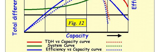
112 Operating Point It is the point of intersection for the system head curve and the pump s characteristic curve. Why we are interested in getting the Operating Point?! To get Q act. for the existing systems. To Select the relevant pump for the new systems
113 How to Get the Operating Point? System head Curve Representing the behavior of the piping system Pump characteristic Curve Representing the behavior of the pump system 3
114 How to get the System Curve H p n = H s + ( i= 1 K + fs. L d s s + fd. L d d d ) v g H. L. L n s s d d p = H s + ( K + + ) i= 1 ds dd f f Q ga Q V R n f H f H p H p H p 0 H s H p1 Q 1 H p1 H s Q H p Q 4 Q 1 Q
115 Special System Curves H s s d d s H p H s + ( K + + ) n = f. L. L i= 1 ds dd f Q ga a) Short pipe or smooth pipe (ideal flow) b) No Static Head (real flow) H s 5
116 System Curve (Cont.) Dynamic Head Static Head Dynamic Head H s >> L p >> 6
117 Factors Affecting System Curve H. L. L n s s d d p = H s + ( K + + ) i= 1 ds dd f f Q ga f H K d p Q 7
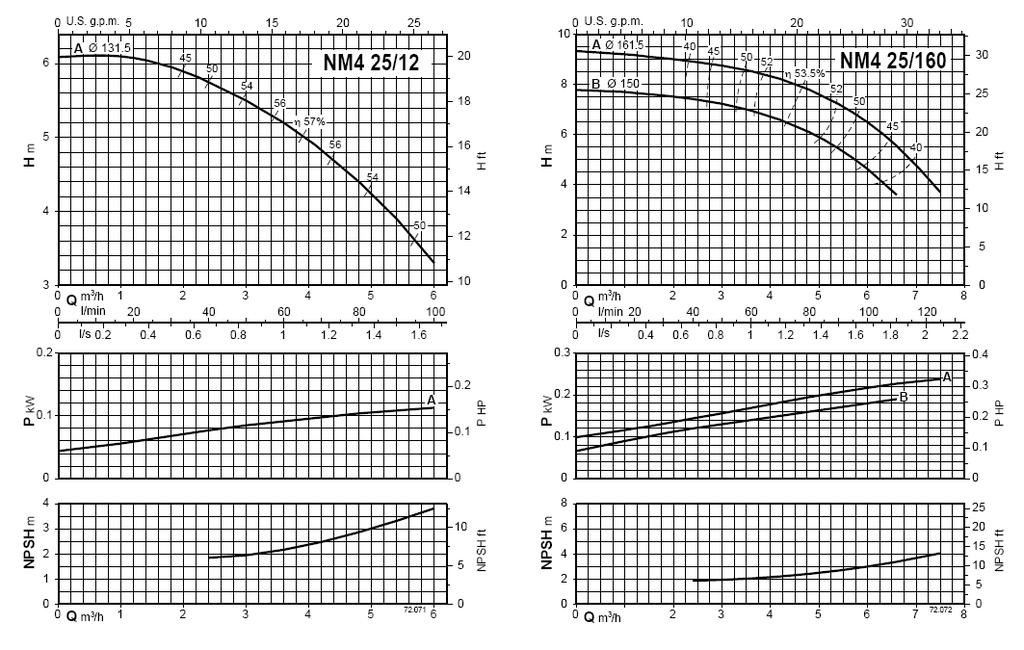
118 Pump (Characteristic) Performance Curves What are the pump performance curves? Hp Power η Q Q Q Pumping head versus discharge Brake horsepower versus discharge Efficiency versus discharge These relations are derived from actual tests on a given pump 8
119 How to Measure Pump Performance Curves? Hp h md Manometric head: H m = h md -h ms Q h ms Sluice valve H p =H m +V d /g-v s /g Orifice meter 9


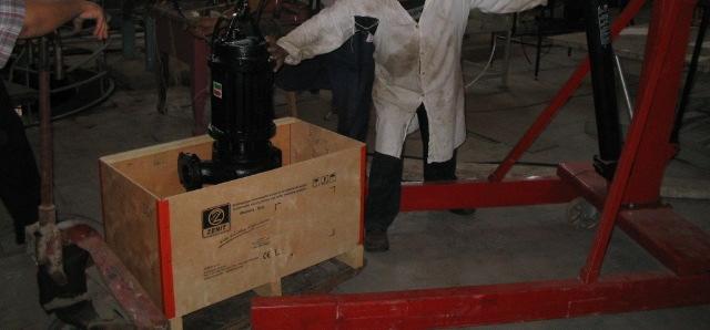
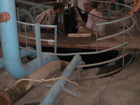
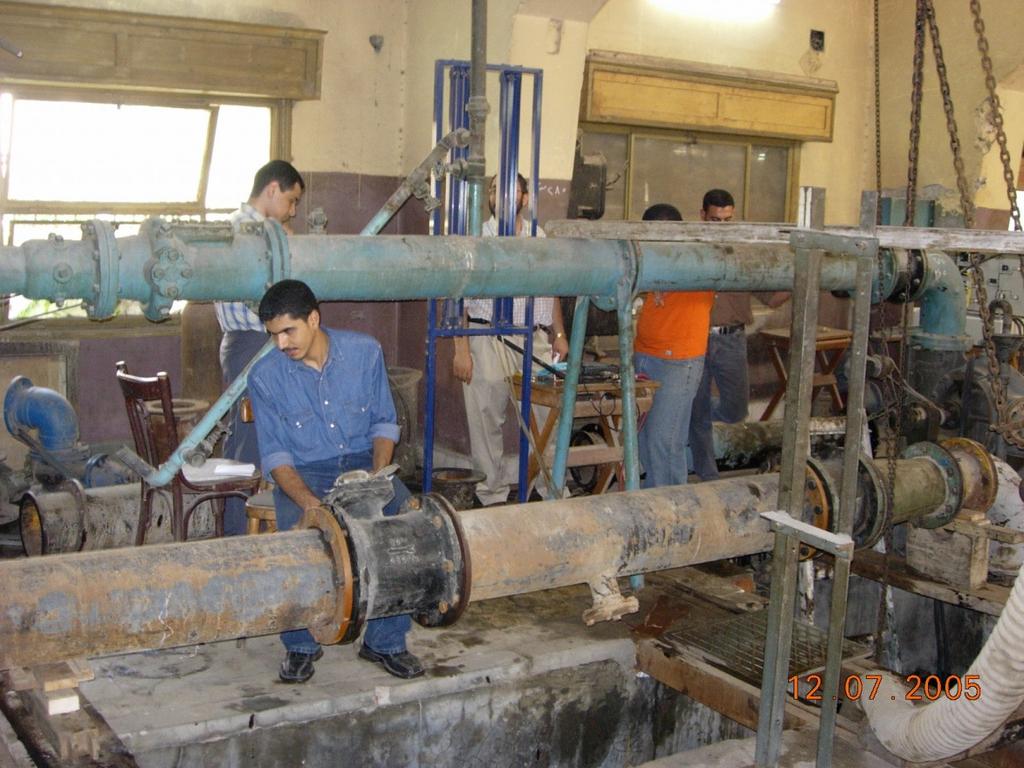
120 Photo Gallery of Actual Pump Performance Test Delivery pipe 10


121 Photo Gallery of Actual Pump Performance Test 11
122 Photo Gallery of Actual Pump Performance Test H H(m) = Q Q R = Q(l/s) 1
123 Three important points on the pump characteristic curve
124 Types of Curves
125 Example of Pumps with Dropping Curves
126 Three important points on the pump characteristic curve The shut-off head, this is the maximum head that the pump can achieve and occurs at zero flow. The pump will be noisy and vibrate excessively at this point. The pump will consume the least amount of power at this point. The best efficiency point B.E.P. this is the point at which the pump is the most efficient and operates with the least vibration and noise. This is often the point for which pumps are rated and which is indicated on the nameplate. The pump will consume the power corresponding to its B.E.P. rating at this point. The maximum flow point, the pump may not operate past this point. The pump will be noisy and vibrate excessively at this point. The pump will consume the maximum amount of power at this point.
127 Factors Affecting Pump Curve Motor Speed N 17
128 Factors Affecting Pump Curve Impeller Size 18
129 Factors Affecting Pump Curve Pump Type From the consistency point of view, which pump type is more preferred? 19
130 Factors Affecting Pump Curve Pump Type (Cont.) Best Efficiency Point (BEP) BEZ = -0%Q bep to +10%Q bep 0
131 Effect of Operation Outside BEZ Radial Forces Significantly Increases
132 Effect of Operation Outside BEZ Vibration Significantly Increases
133 How to Select the Relevant Pump Type? We can easily answer this question if we know the differences between pump types Pump Specific Speed (Ns) N s can be used to differentiate between pumps N s = N.Q 0.5 /H 3/4 Where: N in rpm, Q in m3/s, H in m Kindly Note that: N s is calculated only at the BEP
134 Major Differences in Three Classes of Centrifugal Pumps
135 Example How to Identify Relevant Pump Type A designer needs to select a pump type for pumping of raw wastewater for a local head of 30m and the maximum design capacity is of 0.5 m3/s at an operating speed of 100 rpm. Identify the relevant pump type. Type: Radial (N s <80), Francis Vane Type


136 Example: How to Identify Relevant Pump Type
137 Constant Versus Variable Speed Pumps Item Constant Speed Variable Speed Capability N is constant N could be variable Cost Less expensive More expensive Reliability Most reliable Less reliable Applications Suits mainly the Suits mainly the case of non case of continuous continuous flow flow No. of Required Pumping Units Water Hammer Generally Higher Generally Lower Less harmful in some cases Pumping stations having large variations in flow rates might require more pumping units under constant speed system than those under variable speed system
138 Any Questions?
139 Water Pumps and Pumping Systems By Dr. Mohammed med Haggag Lecture 5: : Pumps Configuration
140 Pump Configuration Pump configuration means how many pumping units are required to satisfy the design requirements (Discharge and Head). The pumping units can be arranged in any of the following configuration: 1- Single Pump. Pumps in Parallel 3. Pumps in Series 4. Pumps in Parallel-Series
141 Single Pump 3
142 How to Select the Relevant Pump? Step#1: Calculate H req and identify pump type via Ns Step#: Get the relevant pump from the pump group chart H H req P I P II P III P V P IV P VI Given: Hs = 0m, Q req = 700 m 3 /hr, L p = d p = Q req Q 4
143 How to Select the Relevant Pump? (Cont.) PII- Curves If PII Type is a Variable Speed Pump Alternative # Step#3: Draw system curve Step#4: Set the point (Q req,h req ) on the system curve. Step#5: Check the possible alternatives. Alternative # 5
144 How to Select the Relevant Pump? (Cont.) If PII Type is a Constant Speed Pump 6
145 Recirculation Line Most centrifugal pumps should not be used at a flow rate less than 50% of the B.E.P. (best efficiency point) flow rate without a recirculation line. (What is the B.E.P.?) If your system requires a flow rate of 50% or less, then use a recirculation line to increase the flow through the pump keeping the flow low in the system, or install a variable speed drive.

146 8

147 9
148 10
149 Pumps in Parallel 11
150 Set of Pumps in Parallel Why? P III H H req P II P VI P I P IV P V Q Q req 1
151 Set of Pumps in Parallel Why? Q t Demand is not constant 13
152 Situations Require Using Pumps in Parallel (summary) 1- If Q des is significantly larger than the available pumps in the market. - If the demand is significantly variable with time. 3- For emergency cases (fire fighting). 4- For pump station upgrade to fulfill future increased demand. 14
153 Operating Point for Pumps in Parallel The main idea is as follow: -convert the set of parallel pumps into one single (virtual) pump. - generate the pump curve of the virtual pump knowing that: H const & Q is added up. - get the operating point (virtual pump curve with the system curve) p 1& p // Q p1 Q tot =Q p1+ Q p Q p p 1 p 15
154 Operating Point for Pumps in Parallel P III H H req P II P VI P I P IV P V Q req / Q Q req 16
155 Operating Point for Pumps in Parallel PIV- Curves Q p 1pw,H,H p 1pw Q tot Q1pw (Q p, H p ) (Q tot, H tot ) (Q 1pw,H 1pw ) (Q req, H req ) (Q req /,H req ) 17
156 General Comments (Q 1p, H 1p ) (Q p, H p ) (Q 3p, H 3p ) 18
157 the capacity of three pumps running will not be much greater than that of two pumps.running 19
158 Important Comment Can I use this pump? H Area prone to cavitations Q 0
159 Important Comment Assume we have two pumps operating in parallel H pumps in // single pump If the pump runs individually, it will experience cavitations Q 1
160 Variation of Operating Point with Time H pumps in // Pump# Pump#1
161 Variation of Operating Point with Time
162 Variation of Operating Point with Time
163 Variation of Operating Point with Time Pumps with such characteristic Curves should be avoided
164 Necessary Fittings of parallel pumps 6
165 Pumps in Series 7
166 Set of Pumps in Series Why? H H req P I P II P V P III P IV P VI Q req Q 8
167 Operating Point for Pumps in Series The main idea is as follow: -convert the set of series pumps into one single (virtual) pump. - generate the pump curve of the virtual pump knowing that: Q const & H is added up. - get the operating point (virtual pump curve with the system curve) Q tot =Q p1 =Q p Q p Q p H tot =H p1 +H p p 1& p H p1 H p p p 1 9
168 Operating Point Adjustment H Suppose that the required discharge is different from the existing actual operating point what can we do? Operating point Required Design Point Q 30
169 Operating Point Adjustment Four solutions are available: H New Operating point after throttling Operating point 1- Use shorter pumping time with Q op instead of Q des. - Use throttle valve/not gate valve to decrease Qop new to Q des 3- Adjust pump speed if possible based on Affinity Laws. 4- Use smaller impeller d (if possible). Required Design Point Q des Q op Q 31
170 Affinity Laws H Equal Efficiency Curve Operating point Required Design Point Q des Q op Q 3
171 Any Questions?
172 Water Pumps and Pumping Systems By Dr. Mohammed med Haggag Lecture 6: Pump Cavitation
173 What is Cavitation? The Heart Attack of a Pump Cavitation comes from the Latin word, Cavus which means cavity. Cavitations take place when negative pressure decreases below a certain value called vapor pressure.
. Another way: Decrease pressure (while T=constant).")
174 Vapor Pressure Two ways to boil water: One way: Increase temperature (while P=constant). Another way: Decrease pressure (while T=constant). 3
175 Cavitation in Water Pumps water vapor bubbles form when the pressure is less than the vapor pressure of water very high pressures (800 MPa or 115,000 psi) develop when the vapor bubbles collapse Vapor pressure e (Pa) Temperature (C)
176 What Happens when Cavitation Takes place? Formation of vapor bubbles at the eye of the impeller (the lowest pressure point). Vapor bubbles are rapidly collapsed. The rapid collapse will cause small shock waves that impact the impeller surface leading to impeller pitting and erosion. 5


177 Locations of Low Pressure Areas inside the Impeller of a Centrifugal Pump So What can we get from that profile?! 6
178 We Can get the following The pressure might be considerably less inside the impeller. i.e. local pressure drop takes place inside the impeller Not at the suction pipe. 7

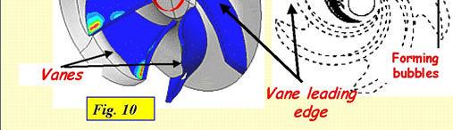
179 Impeller Cavitations Region 8

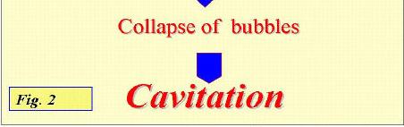
180 Steps of Cavitation 9

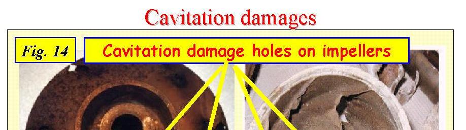
181 Collapse of Bubbles and Pitting Formation 10
182 Symptoms of Cavitations Abnormal sound, noise and vibration; General reduction in pump efficiency; Physical damage of impeller, volute casing. Reduction in the pumped flow, might reach to zero. 11

183 Reduction of Pump Efficiency 1
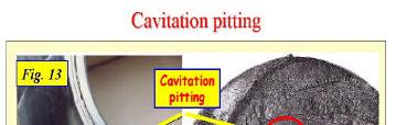
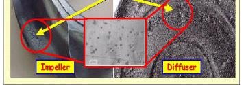
184 Photographic Evidence of Cavitation 13
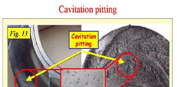
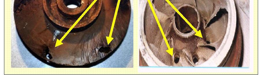
185 Photographic Evidence of Cavitation 14
186 Net Positive Suction Head NPSH R - absolute pressure in excess of vapor pressure required at pump inlet to prevent cavitation given by pump manufacturer determined by the water velocity at the entrance to the pump impeller NPSH A - pressure in excess of vapor pressure available at pump inlet determined by pump installation (elevation above reservoir, frictional losses, water temperature) If NPSH A is less than NPSH R cavitation will occur
187 Cavitation Check h s h ms H atm NPSHA h vap 16
188 Criteria for Checking Cavitations NPSHA = H atm -h ms -h vap NPSHA NPSHR 17
189 NPSH Problem Determine the maximum h s (or the minimum reservoir level) Knowing that T =18 o C, Q=15 l/s, ds = 150 mm, for the given pump type. NPSHA = H atm -h ms -h vap NPSHA = NPSHR NPSHR = H atm -h ms -h vap h ms_max = H atm -h vap - NPSHR 18 C hs=? h ms_max = / =7.6 m h s_max = h ms_max -Sum Losses h s_max < 7.6 m Pvap =000 pa
190 Important Comments Can I use this pump? H Area prone to cavitations Q 19
191 Pump Diagnostic Investigation Problem Statement: A Pump station has two identical pumping units setting in parallel. During the high flow event, no problems have been identified. During the low flow event, significant reduction in the efficiency and increase in the power consumption with some vibrations and noise have been noted. Can you justify with neat sketches what might cause this problem? 0
192 Important Comment Assume we have two pumps operating in parallel H pumps in // single pump If the pump runs individually, it will experience cavitations Q 1


193 Mitigations for No Cavitations Do not use valves Do not use Concentric reducer Use Eccentric one In suction side Avoid high static suction (h s ) Long pipe should be avoided Do not use undersized diameter
194 Concentric Versus Eccentric Reducer 3
195 4
CHAPTER EIGHT P U M P I N G O F L I Q U I D S
 CHAPTER EIGHT P U M P I N G O F L I Q U I D S Pupmps are devices for supplying energy or head to a flowing liquid in order to overcome head losses due to friction and also if necessary, to raise liquid
Pumping Stations Design For Infrastructure Master Program Engineering Faculty-IUG
 umping Stations Design For Infrastructure Master rogram Engineering Faculty-IUG Lecture : umping Hydraulics Dr. Fahid Rabah Water and environment Engineering frabah@iugaza.edu The main items that will
Pressure and Flow Characteristics
 Pressure and Flow Characteristics Continuing Education from the American Society of Plumbing Engineers August 2015 ASPE.ORG/ReadLearnEarn CEU 226 READ, LEARN, EARN Note: In determining your answers to
Hydraulics and hydrology
 Hydraulics and hydrology - project exercises - Class 4 and 5 Pipe flow Discharge (Q) (called also as the volume flow rate) is the volume of fluid that passes through an area per unit time. The discharge
Chapter Four Hydraulic Machines
 Contents 1- Introduction. - Pumps. Chapter Four Hydraulic Machines (لفرع الميكانيك العام فقط ( Turbines. -3 4- Cavitation in hydraulic machines. 5- Examples. 6- Problems; sheet No. 4 (Pumps) 7- Problems;
Chapter Four Hydraulic Machines
 Contents 1- Introduction. 2- Pumps. Chapter Four Hydraulic Machines (لفرع الميكانيك العام فقط ( Turbines. -3 4- Cavitation in hydraulic machines. 5- Examples. 6- Problems; sheet No. 4 (Pumps) 7- Problems;
CIVE HYDRAULIC ENGINEERING PART II Pierre Julien Colorado State University
 1 CIVE 401 - HYDRAULIC ENGINEERING PART II Pierre Julien Colorado State University Problems with and are considered moderate and those with are the longest and most difficult. In 2018 solve the problems
Hydraulics. B.E. (Civil), Year/Part: II/II. Tutorial solutions: Pipe flow. Tutorial 1
, Year/Part: II/II. Tutorial solutions: Pipe flow. Tutorial 1") Hydraulics B.E. (Civil), Year/Part: II/II Tutorial solutions: Pipe flow Tutorial 1 -by Dr. K.N. Dulal Laminar flow 1. A pipe 200mm in diameter and 20km long conveys oil of density 900 kg/m 3 and viscosity
Hydraulics B.E. (Civil), Year/Part: II/II Tutorial solutions: Pipe flow Tutorial 1 -by Dr. K.N. Dulal Laminar flow 1. A pipe 200mm in diameter and 20km long conveys oil of density 900 kg/m 3 and viscosity
COURSE CODE : 3072 COURSE CATEGORY : B PERIODS/ WEEK : 5 PERIODS/ SEMESTER : 75 CREDIT : 5 TIME SCHEDULE
 COURSE TITLE : FLUID MECHANICS COURSE CODE : 307 COURSE CATEGORY : B PERIODS/ WEEK : 5 PERIODS/ SEMESTER : 75 CREDIT : 5 TIME SCHEDULE MODULE TOPIC PERIOD 1 Properties of Fluids 0 Fluid Friction and Flow
9. Pumps (compressors & turbines) Partly based on Chapter 10 of the De Nevers textbook.
 Partly based on Chapter 10 of the De Nevers textbook.") Lecture Notes CHE 31 Fluid Mechanics (Fall 010) 9. Pumps (compressors & turbines) Partly based on Chapter 10 of the De Nevers textbook. Basics (pressure head, efficiency, working point, stability) Pumps
Lecture Notes CHE 31 Fluid Mechanics (Fall 010) 9. Pumps (compressors & turbines) Partly based on Chapter 10 of the De Nevers textbook. Basics (pressure head, efficiency, working point, stability) Pumps
Lesson 37 Transmission Of Air In Air Conditioning Ducts
 Lesson 37 Transmission Of Air In Air Conditioning Ducts Version 1 ME, IIT Kharagpur 1 The specific objectives of this chapter are to: 1. Describe an Air Handling Unit (AHU) and its functions (Section 37.1).
1-Reynold s Experiment
 Lect.No.8 2 nd Semester Flow Dynamics in Closed Conduit (Pipe Flow) 1 of 21 The flow in closed conduit ( flow in pipe ) is differ from this occur in open channel where the flow in pipe is at a pressure
Pipe Flow. Lecture 17
 Pipe Flow Lecture 7 Pipe Flow and the Energy Equation For pipe flow, the Bernoulli equation alone is not sufficient. Friction loss along the pipe, and momentum loss through diameter changes and corners
Applied Fluid Mechanics
 Applied Fluid Mechanics 1. The Nature of Fluid and the Study of Fluid Mechanics 2. Viscosity of Fluid 3. Pressure Measurement 4. Forces Due to Static Fluid 5. Buoyancy and Stability 6. Flow of Fluid and
CENTRIFUGAL PUMP SELECTION, SIZING, AND INTERPRETATION OF PERFORMANCE CURVES
 CENTRIFUGAL PUMP SELECTION, SIZING, AND INTERPRETATION OF PERFORMANCE CURVES 4.0 PUMP CLASSES Pumps may be classified in two general types, dynamic and positive displacement. Positive displacement pumps
EXPERIMENT No.1 FLOW MEASUREMENT BY ORIFICEMETER
 EXPERIMENT No.1 FLOW MEASUREMENT BY ORIFICEMETER 1.1 AIM: To determine the co-efficient of discharge of the orifice meter 1.2 EQUIPMENTS REQUIRED: Orifice meter test rig, Stopwatch 1.3 PREPARATION 1.3.1
Reynolds, an engineering professor in early 1880 demonstrated two different types of flow through an experiment:
 7 STEADY FLOW IN PIPES 7.1 Reynolds Number Reynolds, an engineering professor in early 1880 demonstrated two different types of flow through an experiment: Laminar flow Turbulent flow Reynolds apparatus
Department of Civil and Environmental Engineering CVNG 1001: Mechanics of Fluids
 INTRODUCTION Hydrodynamic Machines A hydromachine is a device used either for extracting energy from a fluid or to add energy to a fluid. There are many types of hydromachines and Figure 1 below illustrates
ME 305 Fluid Mechanics I. Part 8 Viscous Flow in Pipes and Ducts. Flow in Pipes and Ducts. Flow in Pipes and Ducts (cont d)
") ME 305 Fluid Mechanics I Flow in Pipes and Ducts Flow in closed conduits (circular pipes and non-circular ducts) are very common. Part 8 Viscous Flow in Pipes and Ducts These presentations are prepared
ME 305 Fluid Mechanics I Flow in Pipes and Ducts Flow in closed conduits (circular pipes and non-circular ducts) are very common. Part 8 Viscous Flow in Pipes and Ducts These presentations are prepared
CVE 372 HYDROMECHANICS EXERCISE PROBLEMS
 VE 37 HYDROMEHNIS EXERISE PROLEMS 1. pump that has the characteristic curve shown in the accompanying graph is to be installed in the system shown. What will be the discharge of water in the system? Take
REE 307 Fluid Mechanics II. Lecture 1. Sep 27, Dr./ Ahmed Mohamed Nagib Elmekawy. Zewail City for Science and Technology
 REE 307 Fluid Mechanics II Lecture 1 Sep 27, 2017 Dr./ Ahmed Mohamed Nagib Elmekawy Zewail City for Science and Technology Course Materials drahmednagib.com 2 COURSE OUTLINE Fundamental of Flow in pipes
ME 305 Fluid Mechanics I. Chapter 8 Viscous Flow in Pipes and Ducts
 ME 305 Fluid Mechanics I Chapter 8 Viscous Flow in Pipes and Ducts These presentations are prepared by Dr. Cüneyt Sert Department of Mechanical Engineering Middle East Technical University Ankara, Turkey
FE Exam Fluids Review October 23, Important Concepts
 FE Exam Fluids Review October 3, 013 mportant Concepts Density, specific volume, specific weight, specific gravity (Water 1000 kg/m^3, Air 1. kg/m^3) Meaning & Symbols? Stress, Pressure, Viscosity; Meaning
HEADLOSS ESTIMATION. Mekanika Fluida 1 HST
 HEADLOSS ESTIMATION Mekanika Fluida HST Friction Factor : Major losses Laminar low Hagen-Poiseuille Turbulent (Smoot, Transition, Roug) Colebrook Formula Moody diagram Swamee-Jain 3 Laminar Flow Friction
Hydraulic (Piezometric) Grade Lines (HGL) and
 Grade Lines (HGL) and") Hydraulic (Piezometric) Grade Lines (HGL) and Energy Grade Lines (EGL) When the energy equation is written between two points it is expresses as in the form of: Each term has a name and all terms have
Hydraulic (Piezometric) Grade Lines (HGL) and Energy Grade Lines (EGL) When the energy equation is written between two points it is expresses as in the form of: Each term has a name and all terms have
Hydraulics for Urban Storm Drainage
 Urban Hydraulics Hydraulics for Urban Storm Drainage Learning objectives: understanding of basic concepts of fluid flow and how to analyze conduit flows, free surface flows. to analyze, hydrostatic pressure
Chapter 3 Water Flow in Pipes
 The Islamic University o Gaza Faculty o Engineering Civil Engineering Department Hydraulics - ECI 33 Chapter 3 Water Flow in Pipes 3. Description o A Pipe Flow Water pipes in our homes and the distribution
Experiment- To determine the coefficient of impact for vanes. Experiment To determine the coefficient of discharge of an orifice meter.
 SUBJECT: FLUID MECHANICS VIVA QUESTIONS (M.E 4 th SEM) Experiment- To determine the coefficient of impact for vanes. Q1. Explain impulse momentum principal. Ans1. Momentum equation is based on Newton s
FLUID MECHANICS D203 SAE SOLUTIONS TUTORIAL 2 APPLICATIONS OF BERNOULLI SELF ASSESSMENT EXERCISE 1
 FLUID MECHANICS D203 SAE SOLUTIONS TUTORIAL 2 APPLICATIONS OF BERNOULLI SELF ASSESSMENT EXERCISE 1 1. A pipe 100 mm bore diameter carries oil of density 900 kg/m3 at a rate of 4 kg/s. The pipe reduces
Lesson 6 Review of fundamentals: Fluid flow
 Lesson 6 Review of fundamentals: Fluid flow The specific objective of this lesson is to conduct a brief review of the fundamentals of fluid flow and present: A general equation for conservation of mass
Piping Systems and Flow Analysis (Chapter 3)
") Piping Systems and Flow Analysis (Chapter 3) 2 Learning Outcomes (Chapter 3) Losses in Piping Systems Major losses Minor losses Pipe Networks Pipes in series Pipes in parallel Manifolds and Distribution
Piping Systems and Flow Analysis (Chapter 3) 2 Learning Outcomes (Chapter 3) Losses in Piping Systems Major losses Minor losses Pipe Networks Pipes in series Pipes in parallel Manifolds and Distribution
CHAPTER THREE FLUID MECHANICS
 CHAPTER THREE FLUID MECHANICS 3.1. Measurement of Pressure Drop for Flow through Different Geometries 3.. Determination of Operating Characteristics of a Centrifugal Pump 3.3. Energy Losses in Pipes under
M E 320 Professor John M. Cimbala Lecture 23
 M E 320 Professor John M. Cimbala Lecture 23 Today, we will: Discuss diffusers and do an example problem Begin discussing pumps, and how they are analyzed in pipe flow systems D. Diffusers 1. Introduction.
Hydraulic Design Of Polyethylene Pipes
 Hydraulic Design Of Polyethylene Pipes Waters & Farr polyethylene pipes offer a hydraulically smooth bore that provides excellent flow characteristics. Other advantages of Waters & Farr polyethylene pipes,
SUMMER 14 EXAMINATION
 Important Instructions to examiners: 1) The answers should be examined by key words and not as word-to-word as given in the model answer scheme. 2) The model answer and the answer written by candidate
FLOW FRICTION CHARACTERISTICS OF CONCRETE PRESSURE PIPE
 11 ACPPA TECHNICAL SERIES FLOW FRICTION CHARACTERISTICS OF CONCRETE PRESSURE PIPE This paper presents formulas to assist in hydraulic design of concrete pressure pipe. There are many formulas to calculate
Centrifugal Machines Table of Contents
 NLNG Course 017 Table of Contents 1 Introduction and Basic Principles... 1.1 Hydraulic Machines... 1.... 1.3 Pump Geometry... 1.4 Pump Blade Geometry...3 1.5 Diffusers...5 1.6 Pump Losses...6 1.7 Example
AEROSPACE ENGINEERING DEPARTMENT. Second Year - Second Term ( ) Fluid Mechanics & Gas Dynamics
 Fluid Mechanics & Gas Dynamics") AEROSPACE ENGINEERING DEPARTMENT Second Year - Second Term (2008-2009) Fluid Mechanics & Gas Dynamics Similitude,Dimensional Analysis &Modeling (1) [7.2R*] Some common variables in fluid mechanics include:
AEROSPACE ENGINEERING DEPARTMENT Second Year - Second Term (2008-2009) Fluid Mechanics & Gas Dynamics Similitude,Dimensional Analysis &Modeling (1) [7.2R*] Some common variables in fluid mechanics include:
Chapter 6. Losses due to Fluid Friction
 Chapter 6 Losses due to Fluid Friction 1 Objectives ä To measure the pressure drop in the straight section of smooth, rough, and packed pipes as a function of flow rate. ä To correlate this in terms of
Viscous Flow in Ducts
 Dr. M. Siavashi Iran University of Science and Technology Spring 2014 Objectives 1. Have a deeper understanding of laminar and turbulent flow in pipes and the analysis of fully developed flow 2. Calculate
by Dr. Shibayan Sarkar Department of Mechanical Engineering
 Lecture on Pump by Dr. Shibayan Sarkar Department of Mechanical Engineering Indian School of Mines Dhanbad WHAT IS PUMP? A hydrodynamic pump machine is a device which converts the mechanical energy held
Chapter (3) Water Flow in Pipes
 Water Flow in Pipes") Chapter (3) Water Flow in Pipes Water Flow in Pipes Bernoulli Equation Recall fluid mechanics course, the Bernoulli equation is: P 1 ρg + v 1 g + z 1 = P ρg + v g + z h P + h T + h L Here, we want to study
Chapter (3) Water Flow in Pipes Water Flow in Pipes Bernoulli Equation Recall fluid mechanics course, the Bernoulli equation is: P 1 ρg + v 1 g + z 1 = P ρg + v g + z h P + h T + h L Here, we want to study
TOTAL HEAD, N.P.S.H. AND OTHER CALCULATION EXAMPLES Jacques Chaurette p. eng., June 2003
 TOTAL HEAD, N.P.S.H. AND OTHER CALCULATION EXAMPLES Jacques Chaurette p. eng., www.lightmypump.com June 2003 Figure 1 Calculation example flow schematic. Situation Water at 150 F is to be pumped from a
Water Circuit Lab. The pressure drop along a straight pipe segment can be calculated using the following set of equations:
 Water Circuit Lab When a fluid flows in a conduit, there is friction between the flowing fluid and the pipe walls. The result of this friction is a net loss of energy in the flowing fluid. The fluid pressure
LECTURE 6- ENERGY LOSSES IN HYDRAULIC SYSTEMS SELF EVALUATION QUESTIONS AND ANSWERS
 LECTURE 6- ENERGY LOSSES IN HYDRAULIC SYSTEMS SELF EVALUATION QUESTIONS AND ANSWERS 1. What is the head loss ( in units of bars) across a 30mm wide open gate valve when oil ( SG=0.9) flow through at a
Properties and Definitions Useful constants, properties, and conversions
 Properties and Definitions Useful constants, properties, and conversions gc = 32.2 ft/sec 2 [lbm-ft/lbf-sec 2 ] ρwater = 1.96 slugs/ft 3 γwater = 62.4 lb/ft 3 1 ft 3 /sec = 449 gpm 1 mgd = 1.547 ft 3 /sec
2 Internal Fluid Flow
 Internal Fluid Flow.1 Definitions Fluid Dynamics The study of fluids in motion. Static Pressure The pressure at a given point exerted by the static head of the fluid present directly above that point.
When water (fluid) flows in a pipe, for example from point A to point B, pressure drop will occur due to the energy losses (major and minor losses).
 flows in a pipe, for example from point A to point B, pressure drop will occur due to the energy losses (major and minor losses).") PRESSURE DROP AND OSSES IN PIPE When water (luid) lows in a pipe, or example rom point A to point B, pressure drop will occur due to the energy losses (major and minor losses). A B Bernoulli equation:
PRESSURE DROP AND OSSES IN PIPE When water (luid) lows in a pipe, or example rom point A to point B, pressure drop will occur due to the energy losses (major and minor losses). A B Bernoulli equation:
Chapter 7 The Energy Equation
 Chapter 7 The Energy Equation 7.1 Energy, Work, and Power When matter has energy, the matter can be used to do work. A fluid can have several forms of energy. For example a fluid jet has kinetic energy,
Chapter (3) Water Flow in Pipes
 Water Flow in Pipes") Chapter (3) Water Flow in Pipes Water Flow in Pipes Bernoulli Equation Recall fluid mechanics course, the Bernoulli equation is: P 1 ρg + v 1 g + z 1 = P ρg + v g + z h P + h T + h L Here, we want to study
Chapter (3) Water Flow in Pipes Water Flow in Pipes Bernoulli Equation Recall fluid mechanics course, the Bernoulli equation is: P 1 ρg + v 1 g + z 1 = P ρg + v g + z h P + h T + h L Here, we want to study
FE Fluids Review March 23, 2012 Steve Burian (Civil & Environmental Engineering)
") Topic: Fluid Properties 1. If 6 m 3 of oil weighs 47 kn, calculate its specific weight, density, and specific gravity. 2. 10.0 L of an incompressible liquid exert a force of 20 N at the earth s surface.
Topic: Fluid Properties 1. If 6 m 3 of oil weighs 47 kn, calculate its specific weight, density, and specific gravity. 2. 10.0 L of an incompressible liquid exert a force of 20 N at the earth s surface.
UNIT I FLUID PROPERTIES AND STATICS
 SIDDHARTH GROUP OF INSTITUTIONS :: PUTTUR Siddharth Nagar, Narayanavanam Road 517583 QUESTION BANK (DESCRIPTIVE) Subject with Code : Fluid Mechanics (16CE106) Year & Sem: II-B.Tech & I-Sem Course & Branch:
Introduction to Fluid Machines, and Compressible Flow Prof. S. K. Som Department of Mechanical Engineering Indian Institute of Technology, Kharagpur
 Introduction to Fluid Machines, and Compressible Flow Prof. S. K. Som Department of Mechanical Engineering Indian Institute of Technology, Kharagpur Lecture - 09 Introduction to Reaction Type of Hydraulic
WATER DISTRIBUTION NETWORKS
 WATER DISTRIBUTION NETWORKS CE 370 1 Components of Water Supply System 2 1 Water Distribution System Water distribution systems are designed to adequately satisfy the water requirements for a combinations
Contents. 2 Basic Components Aerofoils Force Generation Performance Parameters xvii
 Contents 1 Working Principles... 1 1.1 Definition of a Turbomachine... 1 1.2 Examples of Axial Turbomachines... 2 1.2.1 Axial Hydraulic Turbine... 2 1.2.2 Axial Pump... 4 1.3 Mean Line Analysis... 5 1.4
ENGINEERING FLUID MECHANICS. CHAPTER 1 Properties of Fluids
 CHAPTER 1 Properties of Fluids ENGINEERING FLUID MECHANICS 1.1 Introduction 1.2 Development of Fluid Mechanics 1.3 Units of Measurement (SI units) 1.4 Mass, Density, Specific Weight, Specific Volume, Specific
PUMP SYSTEM ANALYSIS AND SIZING. BY JACQUES CHAURETTE p. eng.
 PUMP SYSTEM ANALYSIS AND SIZING BY JACQUES CHAURETTE p. eng. 5 th Edition February 2003 Published by Fluide Design Inc. www.fluidedesign.com Copyright 1994 I TABLE OF CONTENTS Introduction Symbols Chapter
where = rate of change of total energy of the system, = rate of heat added to the system, = rate of work done by the system
 The Energy Equation for Control Volumes Recall, the First Law of Thermodynamics: where = rate of change of total energy of the system, = rate of heat added to the system, = rate of work done by the system
PROPERTIES OF FLUIDS
 Unit - I Chapter - PROPERTIES OF FLUIDS Solutions of Examples for Practice Example.9 : Given data : u = y y, = 8 Poise = 0.8 Pa-s To find : Shear stress. Step - : Calculate the shear stress at various
Experiment (4): Flow measurement
: Flow measurement") Experiment (4): Flow measurement Introduction: The flow measuring apparatus is used to familiarize the students with typical methods of flow measurement of an incompressible fluid and, at the same time
Experiment (4): Flow measurement Introduction: The flow measuring apparatus is used to familiarize the students with typical methods of flow measurement of an incompressible fluid and, at the same time
 CE 6303 MECHANICS OF FLUIDS L T P C QUESTION BANK 3 0 0 3 UNIT I FLUID PROPERTIES AND FLUID STATICS PART - A 1. Define fluid and fluid mechanics. 2. Define real and ideal fluids. 3. Define mass density
Chapter 10 Flow in Conduits
 Chapter 10 Flow in Conduits 10.1 Classifying Flow Laminar Flow and Turbulent Flow Laminar flow Unpredictable Turbulent flow Near entrance: undeveloped developing flow In developing flow, the wall shear
P & I Design Limited. 2 Reed Street, Gladstone Industrial Estate, Thornaby, TS17 7AF. Tel: +44 (0) Fax: +44 (0)
 Fax: +44 (0)") ump Sizing & Rating USER MANUAL & I Design Limited Reed Street, Gladstone Industrial Estate, Thornaby, TS7 7AF. Tel: +44 (0) 64 67444 Fax: +44 (0) 64 66447 www.pidesign.co.uk Support: sales@pidesign.co.uk
ump Sizing & Rating USER MANUAL & I Design Limited Reed Street, Gladstone Industrial Estate, Thornaby, TS7 7AF. Tel: +44 (0) 64 67444 Fax: +44 (0) 64 66447 www.pidesign.co.uk Support: sales@pidesign.co.uk
Lecture 4. Lab this week: Cartridge valves Flow divider Properties of Hydraulic Fluids. Lab 8 Sequencing circuit Lab 9 Flow divider
 91 Lecture 4 Lab this week: Lab 8 Sequencing circuit Lab 9 Flow divider Cartridge valves Flow divider Properties of Hydraulic Fluids Viscosity friction and leakage Bulk modulus Inertance Cartridge Valves
A Model Answer for. Problem Set #7
 A Model Answer for Problem Set #7 Pipe Flow and Applications Problem.1 A pipeline 70 m long connects two reservoirs having a difference in water level of 6.0 m. The pipe rises to a height of 3.0 m above
Department of Energy Fundamentals Handbook. THERMODYNAMICS, HEAT TRANSFER, AND FLUID FLOW, Module 3 Fluid Flow
 Department of Energy Fundamentals Handbook THERMODYNAMICS, HEAT TRANSFER, AND FLUID FLOW, Module 3 REFERENCES REFERENCES Streeter, Victor L., Fluid Mechanics, 5th Edition, McGraw-Hill, New York, ISBN 07-062191-9.
Chapter (6) Energy Equation and Its Applications
 Energy Equation and Its Applications") Chapter (6) Energy Equation and Its Applications Bernoulli Equation Bernoulli equation is one of the most useful equations in fluid mechanics and hydraulics. And it s a statement of the principle of conservation
Chapter (6) Energy Equation and Its Applications Bernoulli Equation Bernoulli equation is one of the most useful equations in fluid mechanics and hydraulics. And it s a statement of the principle of conservation
Chapter 6. Losses due to Fluid Friction
 Chapter 6 Losses due to Fluid Friction 1 Objectives To measure the pressure drop in the straight section of smooth, rough, and packed pipes as a function of flow rate. To correlate this in terms of the
Design of Monoblock Centrifugal Pump Impeller
 Design of Monoblock Centrifugal Pump Impeller Authors Mr. Chetan Kallappa Tambake 1, Prof. P. V. Salunke 1 Department of Mechanical Engineering, Walchand Institute of Technology, Ashok Chowk, Solapur-413006,
1) Specific Gravity It is the ratio of specific weight of fluid to the specific weight of water.
 Specific Gravity It is the ratio of specific weight of fluid to the specific weight of water.") Important Instructions to examiners: 1) The answers should be examined by key words and not as word-to-word as given in the model answer scheme. 2) The model answer and the answer written by candidate
Important Instructions to examiners: 1) The answers should be examined by key words and not as word-to-word as given in the model answer scheme. 2) The model answer and the answer written by candidate
An overview of the Hydraulics of Water Distribution Networks
 An overview of the Hydraulics of Water Distribution Networks June 21, 2017 by, P.E. Senior Water Resources Specialist, Santa Clara Valley Water District Adjunct Faculty, San José State University 1 Outline
Determining Liquid Capacity 4 th Annual Pipeline Knowledge Retention Chris Sonneborn November 7, 2013
 Determining Liquid Capacity 4 th Annual Pipeline Knowledge Retention Chris Sonneborn November 7, 2013 Outline What is important? Liquid Properties Thermal Conditions Hydraulic Gradient Flow Regime in Liquids
F L U I D S Y S T E M D Y N A M I C S
 F L U I D S Y S T E M D Y N A M I C S T he proper design, construction, operation, and maintenance of fluid systems requires understanding of the principles which govern them. These principles include
Chapter 8: Flow in Pipes
 Objectives 1. Have a deeper understanding of laminar and turbulent flow in pipes and the analysis of fully developed flow 2. Calculate the major and minor losses associated with pipe flow in piping networks
R09. d water surface. Prove that the depth of pressure is equal to p +.
 Code No:A109210105 R09 SET-1 B.Tech II Year - I Semester Examinations, December 2011 FLUID MECHANICS (CIVIL ENGINEERING) Time: 3 hours Max. Marks: 75 Answer any five questions All questions carry equal
Review of pipe flow: Friction & Minor Losses
 ENVE 204 Lecture -1 Review of pipe flow: Friction & Minor Losses Assist. Prof. Neslihan SEMERCİ Marmara University Department of Environmental Engineering Important Definitions Pressure Pipe Flow: Refers
IJREAS Volume 2, Issue 2 (February 2012) ISSN:
 ISSN:") DESIGN AND CFD ANALYSIS OF SINGLE STAGE, END SUCTION, RADIAL FLOW CENTRIFUGAL PUMP FOR MINE DEWATERING APPLICATION Swapnil Urankar * Dr. H S Shivashankar ** Sourabh Gupta *** ABSTRACT Heavy centrifugal
DESIGN AND CFD ANALYSIS OF SINGLE STAGE, END SUCTION, RADIAL FLOW CENTRIFUGAL PUMP FOR MINE DEWATERING APPLICATION Swapnil Urankar * Dr. H S Shivashankar ** Sourabh Gupta *** ABSTRACT Heavy centrifugal
mywbut.com Hydraulic Turbines
 Hydraulic Turbines Hydro-electric power accounts for up to 0% of the world s electrical generation. Hydraulic turbines come in a variety of shapes determined by the available head and a number of sizes
Experimental and Numerical Investigations of the Effect of Net Positive Suction Head on Water Hammer In Pipeline Systems
 International Journal of Engineering and Advanced Technology (IJEAT) ISSN: 2249 8958, Volume-3, Issue-1, October 2013 Experimental and Numerical Investigations of the Effect of Net Positive Suction Head
Lecture 13 Flow Measurement in Pipes. I. Introduction
 Lecture 13 Flow Measurement in Pipes I. Introduction There are a wide variety of methods for measuring discharge and velocity in pipes, or closed conduits Many of these methods can provide very accurate
FLOW IN PIPES. Mark J McCready University of Notre Dame July 24, chemeprof.com
 FLOW IN PIPES Mark J McCready University of Notre Dame July 24, 2017 OVERVIEW This lecture will provide the simplest framework to explain The three forces at that are important to fluid flow in pipes The
HYDRAULIC TURBINES. Hydraulics and Hydraulic Machines
 HYDRAULIC TURBINES Introduction: The device which converts h ydraulic energy into mechanical energy or vice versa is known as Hydraulic Machines. The h ydraulic machines which convert h ydraulic energy
ME3560 Tentative Schedule Spring 2019
 ME3560 Tentative Schedule Spring 2019 Week Number Date Lecture Topics Covered Prior to Lecture Read Section Assignment Prep Problems for Prep Probs. Must be Solved by 1 Monday 1/7/2019 1 Introduction to
MAHARASHTRA STATE BOARD OF TECHNICAL EDUCATION
 Important Instructions to examiners: 1) The answers should be examined by key words and not as word-to-word as given in the model answer scheme. 2) The model answer and the answer written by candidate
CHAPTER TWO CENTRIFUGAL PUMPS 2.1 Energy Transfer In Turbo Machines
 7 CHAPTER TWO CENTRIFUGAL PUMPS 21 Energy Transfer In Turbo Machines Fig21 Now consider a turbomachine (pump or turbine) the total head (H) supplied by it is The power delivered to/by the fluid simply
10.52 Mechanics of Fluids Spring 2006 Problem Set 3
 10.52 Mechanics of Fluids Spring 2006 Problem Set 3 Problem 1 Mass transfer studies involving the transport of a solute from a gas to a liquid often involve the use of a laminar jet of liquid. The situation
ME3560 Tentative Schedule Fall 2018
 ME3560 Tentative Schedule Fall 2018 Week Number 1 Wednesday 8/29/2018 1 Date Lecture Topics Covered Introduction to course, syllabus and class policies. Math Review. Differentiation. Prior to Lecture Read
Fluid Statics, Hydrodynamics and Hydraulic Machines
 Fluid Statics, Hydrodynamics and Hydraulic Machines Bobby Rauf 1 Fluid Facts 1) Liquids and gases can both be categorized as fluids. 2) Liquid fluids are assumed be incompressible. 3) Gaseous fluids are
FLUID MECHANICS AND MACHINERY LABORATORY
 FLUID MECHANICS AND MACHINERY LABORATORY STUDENTS REFERENCE MANUAL K.L.UNIVERSITY DEPARTMENT OF CIVIL ENGINEERING Compiled By P.SUNDARA KUMAR, M.Tech (PhD) Associate Professor 1 Preface In most of the
Pipe Flow Design 1. Results Data
 Pipe Flow Design 1 Results Data Color of Pipe: Velocity in m/sec 1.9 2.2 2.4 2.7 2.9 3.2 Pipe Flow Expert Results Key f = flow in Modelling a 'Tee' fitting: The flow rate through the 'Tee' w ill be different
FACULTY OF CHEMICAL & ENERGY ENGINEERING FLUID MECHANICS LABORATORY TITLE OF EXPERIMENT: MINOR LOSSES IN PIPE (E4)
") FACULTY OF CHEMICAL & ENERGY ENGINEERING FLUID MECHANICS LABORATORY TITLE OF EXPERIMENT: MINOR LOSSES IN PIPE (E4) 1 1.0 Objectives The objective of this experiment is to calculate loss coefficient (K
FACULTY OF CHEMICAL & ENERGY ENGINEERING FLUID MECHANICS LABORATORY TITLE OF EXPERIMENT: MINOR LOSSES IN PIPE (E4) 1 1.0 Objectives The objective of this experiment is to calculate loss coefficient (K
INSTITUTE OF AERONAUTICAL ENGINEERING Dundigal, Hyderabad AERONAUTICAL ENGINEERING QUESTION BANK : AERONAUTICAL ENGINEERING.
 Course Name Course Code Class Branch INSTITUTE OF AERONAUTICAL ENGINEERING Dundigal, Hyderabad - 00 0 AERONAUTICAL ENGINEERING : Mechanics of Fluids : A00 : II-I- B. Tech Year : 0 0 Course Coordinator
Chapter 8: Flow in Pipes
 8-1 Introduction 8-2 Laminar and Turbulent Flows 8-3 The Entrance Region 8-4 Laminar Flow in Pipes 8-5 Turbulent Flow in Pipes 8-6 Fully Developed Pipe Flow 8-7 Minor Losses 8-8 Piping Networks and Pump
Major and Minor Losses
 Abstract Major and Minor Losses Caitlyn Collazo, Team 2 (1:00 pm) A Technovate fluid circuit system was used to determine the pressure drop across a pipe section and across an orifice. These pressure drops
STEADY FLOW THROUGH PIPES DARCY WEISBACH EQUATION FOR FLOW IN PIPES. HAZEN WILLIAM S FORMULA, LOSSES IN PIPELINES, HYDRAULIC GRADE LINES AND ENERGY
 STEADY FLOW THROUGH PIPES DARCY WEISBACH EQUATION FOR FLOW IN PIPES. HAZEN WILLIAM S FORMULA, LOSSES IN PIPELINES, HYDRAULIC GRADE LINES AND ENERGY LINES 1 SIGNIFICANCE OF CONDUITS In considering the convenience
Trial dredging by a new ejector-pump system for the reservoir sedimentation
 Trial dredging by a new ejector-pump system for the reservoir sedimentation T. Temmyo, N. Miura & T. Okabe Hazama Corporation, Tokyo, Japan M. Kaku, T. Kammera, & Y. Yamagami Kyushu Electric Power Co.,
Chapter Four fluid flow mass, energy, Bernoulli and momentum
 4-1Conservation of Mass Principle Consider a control volume of arbitrary shape, as shown in Fig (4-1). Figure (4-1): the differential control volume and differential control volume (Total mass entering
CALIFORNIA POLYTECHNIC STATE UNIVERSITY Mechanical Engineering Department ME 347, Fluid Mechanics II, Winter 2018
 CALIFORNIA POLYTECHNIC STATE UNIVERSITY Mechanical Engineering Department ME 347, Fluid Mechanics II, Winter 2018 Date Day Subject Read HW Sept. 21 F Introduction 1, 2 24 M Finite control volume analysis
Mechanical Engineering Programme of Study
 Mechanical Engineering Programme of Study Fluid Mechanics Instructor: Marios M. Fyrillas Email: eng.fm@fit.ac.cy SOLVED EXAMPLES ON VISCOUS FLOW 1. Consider steady, laminar flow between two fixed parallel
V/ t = 0 p/ t = 0 ρ/ t = 0. V/ s = 0 p/ s = 0 ρ/ s = 0
 UNIT III FLOW THROUGH PIPES 1. List the types of fluid flow. Steady and unsteady flow Uniform and non-uniform flow Laminar and Turbulent flow Compressible and incompressible flow Rotational and ir-rotational