Hydraulics for Urban Storm Drainage
|
|
|
- Grant Cameron
- 6 years ago
- Views:
Transcription
1 Urban Hydraulics
2 Hydraulics for Urban Storm Drainage Learning objectives: understanding of basic concepts of fluid flow and how to analyze conduit flows, free surface flows. to analyze, hydrostatic pressure force on a surface steady pressurized flows through conduits force exerted by steady fluid flows steady open channel flows to derive mathematical formulation for estimation of flood water levels and inundation areas due to floods.
3 What is Fluid? Fluid Deforms continuously under the action of an applied shear stress. Both liquids and gases Conforms to the shape of its container. Liquid retains its own volume, gas takes the full volume of the container Solid When subjected to a shear stress deforms depending on the force and attains a final equilibrium position.
4 Continuum concept Fluid is considered as continuous substance The conditions at a point is the average of a very large number of molecules surrounding the point within a radius large compared to the intermolecular distance The variation of fluid and flow properties from point to point is considered to be smooth Any property at a point (x,y,z) at time t can be expressed as φ(x,y,z,t).
5 Properties of Fluids Density ρ Mass per unit volume [M/L 3 ] Bulk Modulus K Ratio between volumetric stress and volumetric strain [ ML 1 T ] Viscosity μ Property of a fluid that enables it to develop resistance to deformation [ML 1 T 1 ] Surface tension Measured as the force acting across a unit length of line drawn in the surface [MT ]
6 Fluid statics All the particles of the fluid are motionless. No Shear stresses Pressure at a point is the same in all directions Pressures at the same level in a continuous expanse of a static fluid are same e.g. two points at the same elevation in a U tube manometer.

7 Hydrostatic forces Hydrostatic pressure on the surface increases linearly with depth
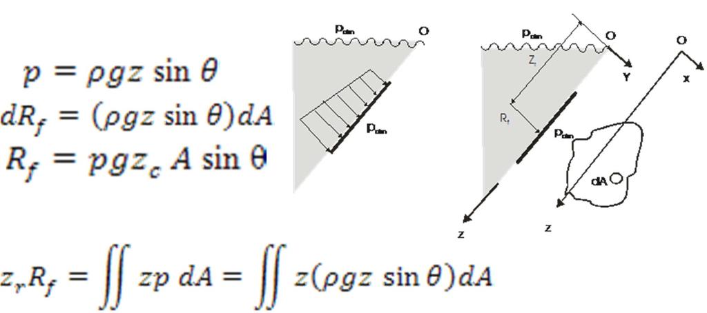
8 Hydrostatic forces
9 Steady flow Types of fluid flows Properties at a point do not change with time. (at a point (x,y,z) at time t any property is φ(x,y,z,t) = φ(x,y,z) only) Uniform flow Properties at a given instant are same in magnitude and direction at every point in the fluid flow. (at a point (x,y,z) at time t any property is φ(x,y,z,t) = φ(t) only)

10 Types of fluid flows Fluid flows Steady flows Unsteady flows Fluid flows Steady uniform flows Steady nonuniform flows Unsteady uniform flows Unsteady nonuniform flows
11 Control volume Control Volume Concept A definite volume in space with fixed boundaries through which matter is allowed to cross. The effect of fluid flow on its boundaries are of more interest The conservation laws are applied to control volumes to describe changes of flow properties
12 Reynolds Transport Equation N is an extensive property At t, N S, t N C, t At t + Δt, N N C, t t S,, tt dn dt C dn dt S N N in in N N out out System boundary & CV (a) Control volume and system at t System boundary CV Reynolds Transport Equation (b) Control volume and system at t =t +δt
13 Mass Continuity Equation Let N be the mass m. Since the mass in the system is constant, m in dm C dt m out dm S dm dt dt C 0 m in m out For steady flow m m in out

14 Mass Continuity Equation CV Q Unsteady flow continuity equation:
15 Force Momentum Equation Let N be the linear momentum of fluid in X direction, M X. From Newton s Second law M Xin dm XC dt F XS M Xout F XS F XS dm dt dm XC dt XS M X out M X in For Steady flow F XS M X out M X in
16 Steady flow Speed of incoming jet = v 1 Speed of outgoing jet = v Diameter of jet = D Force on the vane? Force Momentum Equation Impact force on a vane Continuity Equation:
17 Application of Force Momentum Equation: In X direction: In Y direction: Force Momentum Equation Impact force on a vane
18 Energy Equation Let N be the total energy (E) de dt des dt E C des E in E dt dqs dw S dt dt m (u + V /+gz) out For steady, adiabatic flow, E in de C dt d E out W dt S no change in Internal Energy
19 Bernoulli s Equation When there is no shaft work, viscous work, shear work, electromagnetic work, change in internal energy Application of Bernoulli s Equation limits to steady, inviscid, incompressible flow along a stream line.
20 Bernoulli s Equation H (Total Head) = p/ρ (pressure head) + V /(velocity head) + gz (elevation head) = constant The total head which is the energy per unit weight of the fluid is constant along a streamline in a steady, incompressible, inviscid fluid flow
21 Bernoulli s Equation H p g V g z Constant p g V g H z Elevation datum
22 Force Momentum Equation Force on a bend Steady incompressible flow through a bend Force on the bend? Continuity equation: Bernoulli equation:
23 Force Momentum Equation Force on a bend In the vertical direction, force is Rz No change in momentum Force Momentum Equation in Z direction,
24 Force Momentum Equation Force on a bend Forces in x direction: Rate of change of Momentum in x direction: Force momentum equation in x direction:
25 Laminar and turbulent flows In laminar flow Fluid particles move in layers, with one layer sliding smoothly over an adjacent layer. Random fluctuations in particle velocities are damped by the viscous forces and orderly flow is maintained.
26 Laminar and turbulent flows In turbulent flow, Fluid particles deviate to move from orderly manner and viscous shear stresses are not sufficient to eliminate the random fluctuations.
27 Laminar and turbulent flows Reynolds Number (Re = ρvl) / µ ) proportional to ratio of forces inertia force/viscous force criterion to determine whether flow is laminar or turbulent when the Reynolds Number is below a critical value of [( ρvd) / µ]= 000, pipe flow is normally laminar.
 results in more even velocity profile")

28 Laminar and turbulent flows In turbulent flows, compared to laminar flow, mixing of fluid (transfer of momentum) results in more even velocity profile at a pipe section Wall shear stress is greater Energy loss rate is higher Pipe roughness is also an important factor Shear stress = du/dy w Laminar w Turbulent
29 Pressurized flow in conduits Flow is driven by the total head difference at the two ends of the conduit Head loss between two sections is equal to difference in total head at the sections
30 Pressurized flow in conduits Total headline or total energy grade line (EGL) referred to the datum Hydraulic grade line (HGL) or piezometric head line referred to the datum
31 Friction losses in pipe flows Friction loss depends on geometric properties, fluid properties and flow properties semi empirical or empirical equations established based on experimental investigations to estimate friction loss Darcy Weisbach equation Hazen Williams equation Manning s equation Chezy s equation.
32 The Darcy Weisbach equation Where, h L = head loss due to friction f = f(re, ε/d) is the friction factor Re = ρvd/µ ε/d = relative roughness ε = equivalent sand grain roughness of the pipe L = pipe length D = pipe diameter V = cross-sectionally averaged velocity of the flow g = gravitational acceleration
33 The Darcy Weisbach equation For Re <,000, where the flow is laminar flow, f depends only on the Re. f = 64/Re For large Re where the flow is fully turbulent f depends only on the relative roughness of the pipe. In the transitional region between laminar and fully turbulent flow, f depends on both Re and relative roughness.
34 The Darcy Weisbach equation Moody diagram 0 Values of (VD) for water at 60 F [Diameter (D) in in., Velocity (V) in ft/sec] , Laminar flow, f = 64 Re 0.05 h L L V D g Friction factor, f = (10 ) e, ft. e, mm. Riveted steel Concrete Wood stave Cast iron Galvanized iron Asphalted cast iron Steel or wrought iron Drawn Tubing Smooth pipes (10 4 ) (10 5 ) (10 6 ) (10 7 ) Relative roughness, e /D Reynolds number, Re = VD n
35 The Hazen Williams Equation Primarily used for water distribution design V = C f C h R 0.63 S f 0.54 Where V = flow velocity C f = a unit conversion factor (0.849 for SI units) C h = Hazen Williams resistance coefficient R = hydraulic radius S f = Energy gradient

36 Minor losses energy losses at fittings in pipelines, entrance and exits of reservoirs/man holes, pipe expansion and contractions, changes in pipe alignment Head loss at a fitting is expressed as V h L K g Where V K = velocity at the downstream = loss coefficient

37 , Loss coefficients Fitting Flanged 90 o elbow K Globe valve fully open Flange T joint Line flow Branch flow Sudden expansion referred to upstream velocity head. D 1 and D : upstream and downstream velocities respectively
38 Pipe Flow 1 75 m 10m Z = 130 m K exit =1 150 m f =.035 Oil density = 9.0 kn/m 3 Oil flows from the upper reservoir to lower reservoir through a pipe with the diameter of 150mm. If the velocity in the pipe is 1.8m/s, find the elevation of the oil surface in the upper reservoir? Loss Coefficients : K bend = 0.19, K entrance = 0.5, K exit = 1
39 Pipe Flow 1 Z 1 =? 75 m 10 m Z = 130 m K exit =1 Datum 150 m Head balance between (1) and (): Z 1 = m m + H minor H minor = K bend V /g + K ent V /g + K out V /g From Loss Coefficients : K bend = 0.19 K entrance = 0.5 K out = 1 H minor = (0.19x ) * (1.8 /*9.8) = 0.31 m
40 Pipe Flow 1 Z 1 =? 75 m 10 m Z = 130 m K out =1 150 m Z 1 = m + H major + H minor Z 1 = m m m Z 1 = meters


41 Types of open channel flows Steady uniform Flow Gradually Varied Flow Open Channel Flow Steady Flow Unsteady Flow Steady nonuniform Flow Unsteady uniform Flow Rapidly Varied Flow Gradually Varied Flow Unsteady nonuniform Flow Rapidly Varied Flow
42 Open channel geometry factors T d A P Hydraulic radius, R = A/P Hydraulic depth, D h = A/T A = cross sectional area P = wetted perimeter T = top width
43 Force Momentum Equation in the direction perpendicular to the flow, Assumption: the acceleration of flow in the direction is negligible. cos 0 cos Pressure Variation in Open Channel Flow In an open channel flow with small bottom slope and no flow acceleration in the direction perpendicular to the flow, the pressure distribution is hydrostatic.
44 Total Head V H Z d cos g Where, Z = channel bottom elevation d = depth of flow normal to the channel bottom θ = channel slope angle, S o = sin θ α = a velocity distribution coefficient defined by A = cross sectional area V = average flow velocity Energy Relationships Z 1 d 1 1V1 cos g Z d V cos g h L
45 Specific Energy Specific energy, E is the energy head relative to channel bottom elevation E y V Q y g ga A T A y Alternate depths y y = y c Critical depth E min = E C E
46 Specific Energy A) Channel width decreases, discharge per unit width q1 q B) Channel bed level decreases E1 E E y q q y gy gy E 1 E z
47 Critical Flow Depth E becomes minimum at the critical flow Critical depth y c de dy 1 Q ga da dy 1 Q T ga 3 0 Q T ga 3 1 Froude No., Fr Q T 3 ga 1/ V gd h ; Fr C 1 E min y c c V g y c D h c
48 Rectangular channel T= B, A = B.y and D h = y At critical flow, q = discharge per unit width gy V ga B Q Fr 1/ g q gb Q y c min c c c c y y g V y E gy q y g V y E
49 Uniform Flow motivating forces = resistive forces S f =S 0 W sinθ = γals 0 τ = γr n S 0 y n = Depth is called normal depth or uniform depth
50 Flow Resistance Constitutive relationships for uniform flow The Manning Equation (for metric units) 1 / 3 1/ V R n S o n V = cross sectional averaged flow velocity n = Manning s roughness coefficient The Chezy Equation V C RS f C = Chezy s Constant (m 0.5 /s)
51 Momentum forces L P 1 Wsin For steady flow F s P 1 Wsin P, R y y 1 W sin R f q(v f v 1 ) v 1 W v R f P sin

52 Hydraulic jump The hydraulic jump is a phenomenon that occurs when the flow in an open channel changes abruptly from supercritical flow to subcritical flow, with a considerable loss of energy
53 Hydraulic jump If y 1 and y are conjugate depths Momentum equation neglecting friction force, 1 1 Continuity equation, Fr 1 1 Head loss at the hydraulic jump, Fr
54 Gradually varied flow occurs in an open channel reach when the motivating force and the resistance forces are not balanced Hydrostatic pressures can be assumed to exist in the flow and uniform flow, H Z E Z y Q ga
55 Gradually varied flow Fr / / 0 1Fr
56 Computation of gradually varied flow profiles The direct-step method a simple method applicable to prismatic channels E 1 and E are specific energy at sections 1 and respectively In the computations S f is calculated for depths y 1 and y and the average of two values are taken in the equation.
57 Classification of Flow Profiles Flow profiles are classified based on the relative position of normal depth, y. Ify y c hydraulically mild channel slope. (M curve) Ify = y c critical slope. (C curve If y y c hydraulically steep slope. (S curve)
58 Flood hydraulics Flood is an unsteady flow phenomenon and is due to unusual discharge Based on different approximations to represent hydrological processes involved Various methods to carry out flood analysis Selection of the method is justified by the objective of the analysis, availability of data and resources. Simple lumped methods, or hydrologic models, based on the principle of conservation of mass fails to consider the influence of downstream flow conditions that control the flow in subcritical flow conditions
59 Hydraulic models Physically based distributed models (or Hydraulic models) are based on the simultaneous solution of continuity equation and approximated momentum equations. Different models of varying complexities developed with different approximations used to simplify the momentum equations
60 Channel routing A flood discharge at moderate floods may be carried within the stream cross section and designated flood plain. In this case, the analysis is carried out to determine the behavior of flood hydrograph
61 River routing Muskingum method Volume stored in channel reach S K[ XI (1 X ) Q] K = proportionality coefficient S = travel time through the reach X = a dimensionless weighting factor ( ) I = inflow discharge into the reach (m 3 /s) Q = outflow discharge from the reach (m 3 /s) Continuity equation to the reach S S 1 I 1 I t Q 1 Q Q C0I C1I1 CQ t C 0 0.5t KX K(1 X ) 0.5t KX 0.5t C1 K(1 X ) 0.5t K(1 C K(1 X ) 0.5t X ) 0.5t
62 River routing Muskingum-Cunge method Muskingum coefficients 0 T = top width, Δx = distance step equal to C. Δt
63 Hydraulics channel routing models Discharge and water levels are calculated simultaneously by the application of laws of mass and momentum conservation One dimensional models Saint Venant equations, Continuity Eqn Q A 0 x t Momentum Eqn Q t x Q A H ga x gas f 0
64 Kinematic wave model St Venant Eqns are approximated to Q A Continuity Eqn 0 x t Momentum Eqn S f S 0 Kinematic wave model is applicable when the slope dominates in the momentum equation The flood peak discharge will move downstream at a velocity c with no attenuation. Velocity c, called kinematic wave celerity, along the channel c dq da. 1 T dq dy
65 Diffusion wave model St Venant Eqns are approximated to Continuity Eqn Q A 0 x t Momentum Eqn H x S f 0 The diffusion wave model is applied when the slopes are not large and when backwater effect is dominant
66 Two dimensional hydraulic models Two dimensional models are based on Continuity equation Two momentum equations Above equations are depth averaged to derive governing equations of D models e.g. Shallow Water Equations
67 Solution of hydraulic models Numerical methods are used to solve the governing equations of hydraulic models as analytic methods are not able to solve them. Numerical methods need to solve the equations for both space and time Equations are discretized in the D domain using finite volume method, finite element method, etc.
Hydraulics and hydrology
 Hydraulics and hydrology - project exercises - Class 4 and 5 Pipe flow Discharge (Q) (called also as the volume flow rate) is the volume of fluid that passes through an area per unit time. The discharge
FE Fluids Review March 23, 2012 Steve Burian (Civil & Environmental Engineering)
") Topic: Fluid Properties 1. If 6 m 3 of oil weighs 47 kn, calculate its specific weight, density, and specific gravity. 2. 10.0 L of an incompressible liquid exert a force of 20 N at the earth s surface.
Topic: Fluid Properties 1. If 6 m 3 of oil weighs 47 kn, calculate its specific weight, density, and specific gravity. 2. 10.0 L of an incompressible liquid exert a force of 20 N at the earth s surface.
UNIFORM FLOW CRITICAL FLOW GRADUALLY VARIED FLOW
 UNIFORM FLOW CRITICAL FLOW GRADUALLY VARIED FLOW Derivation of uniform flow equation Dimensional analysis Computation of normal depth UNIFORM FLOW 1. Uniform flow is the flow condition obtained from a
OPEN CHANNEL FLOW. One-dimensional - neglect vertical and lateral variations in velocity. In other words, Q v = (1) A. Figure 1. One-dimensional Flow
 A. Figure 1. One-dimensional Flow") OPEN CHANNEL FLOW Page 1 OPEN CHANNEL FLOW Open Channel Flow (OCF) is flow with one boundary exposed to atmospheric pressure. The flow is not pressurized and occurs because of gravity. Flow Classification
OPEN CHANNEL FLOW Page 1 OPEN CHANNEL FLOW Open Channel Flow (OCF) is flow with one boundary exposed to atmospheric pressure. The flow is not pressurized and occurs because of gravity. Flow Classification
Lesson 6 Review of fundamentals: Fluid flow
 Lesson 6 Review of fundamentals: Fluid flow The specific objective of this lesson is to conduct a brief review of the fundamentals of fluid flow and present: A general equation for conservation of mass
Closed duct flows are full of fluid, have no free surface within, and are driven by a pressure gradient along the duct axis.
 OPEN CHANNEL FLOW Open channel flow is a flow of liquid, basically water in a conduit with a free surface. The open channel flows are driven by gravity alone, and the pressure gradient at the atmospheric
Chapter 10 Flow in Conduits
 Chapter 10 Flow in Conduits 10.1 Classifying Flow Laminar Flow and Turbulent Flow Laminar flow Unpredictable Turbulent flow Near entrance: undeveloped developing flow In developing flow, the wall shear
NPTEL Quiz Hydraulics
 Introduction NPTEL Quiz Hydraulics 1. An ideal fluid is a. One which obeys Newton s law of viscosity b. Frictionless and incompressible c. Very viscous d. Frictionless and compressible 2. The unit of kinematic
CIE4491 Lecture. Hydraulic design
 CIE4491 Lecture. Hydraulic design Marie-claire ten Veldhuis 19-9-013 Delft University of Technology Challenge the future Hydraulic design of urban stormwater systems Focus on sewer pipes Pressurized and
REE 307 Fluid Mechanics II. Lecture 1. Sep 27, Dr./ Ahmed Mohamed Nagib Elmekawy. Zewail City for Science and Technology
 REE 307 Fluid Mechanics II Lecture 1 Sep 27, 2017 Dr./ Ahmed Mohamed Nagib Elmekawy Zewail City for Science and Technology Course Materials drahmednagib.com 2 COURSE OUTLINE Fundamental of Flow in pipes
Review of pipe flow: Friction & Minor Losses
 ENVE 204 Lecture -1 Review of pipe flow: Friction & Minor Losses Assist. Prof. Neslihan SEMERCİ Marmara University Department of Environmental Engineering Important Definitions Pressure Pipe Flow: Refers
An overview of the Hydraulics of Water Distribution Networks
 An overview of the Hydraulics of Water Distribution Networks June 21, 2017 by, P.E. Senior Water Resources Specialist, Santa Clara Valley Water District Adjunct Faculty, San José State University 1 Outline
Chapter 6. Losses due to Fluid Friction
 Chapter 6 Losses due to Fluid Friction 1 Objectives ä To measure the pressure drop in the straight section of smooth, rough, and packed pipes as a function of flow rate. ä To correlate this in terms of
Reynolds, an engineering professor in early 1880 demonstrated two different types of flow through an experiment:
 7 STEADY FLOW IN PIPES 7.1 Reynolds Number Reynolds, an engineering professor in early 1880 demonstrated two different types of flow through an experiment: Laminar flow Turbulent flow Reynolds apparatus
V/ t = 0 p/ t = 0 ρ/ t = 0. V/ s = 0 p/ s = 0 ρ/ s = 0
 UNIT III FLOW THROUGH PIPES 1. List the types of fluid flow. Steady and unsteady flow Uniform and non-uniform flow Laminar and Turbulent flow Compressible and incompressible flow Rotational and ir-rotational
s and FE X. A. Flow measurement B. properties C. statics D. impulse, and momentum equations E. Pipe and other internal flow 7% of FE Morning Session I
 Fundamentals of Engineering (FE) Exam General Section Steven Burian Civil & Environmental Engineering October 26, 2010 s and FE X. A. Flow measurement B. properties C. statics D. impulse, and momentum
Viscous Flow in Ducts
 Dr. M. Siavashi Iran University of Science and Technology Spring 2014 Objectives 1. Have a deeper understanding of laminar and turbulent flow in pipes and the analysis of fully developed flow 2. Calculate
FLUID MECHANICS. Dynamics of Viscous Fluid Flow in Closed Pipe: Darcy-Weisbach equation for flow in pipes. Major and minor losses in pipe lines.
 FLUID MECHANICS Dynamics of iscous Fluid Flow in Closed Pipe: Darcy-Weisbach equation for flow in pipes. Major and minor losses in pipe lines. Dr. Mohsin Siddique Assistant Professor Steady Flow Through
Closed duct flows are full of fluid, have no free surface within, and are driven by a pressure gradient along the duct axis.
 OPEN CHANNEL FLOW Open channel flow is a flow of liquid, basically water in a conduit with a free surface. The open channel flows are driven by gravity alone, and the pressure gradient at the atmospheric
Lecture Note for Open Channel Hydraulics
 Chapter -one Introduction to Open Channel Hydraulics 1.1 Definitions Simply stated, Open channel flow is a flow of liquid in a conduit with free space. Open channel flow is particularly applied to understand
Fluid Mechanics. du dy
 FLUID MECHANICS Technical English - I 1 th week Fluid Mechanics FLUID STATICS FLUID DYNAMICS Fluid Statics or Hydrostatics is the study of fluids at rest. The main equation required for this is Newton's
Chapter 3 Water Flow in Pipes
 The Islamic University o Gaza Faculty o Engineering Civil Engineering Department Hydraulics - ECI 33 Chapter 3 Water Flow in Pipes 3. Description o A Pipe Flow Water pipes in our homes and the distribution
Open Channel Flow Part 2. Ch 10 Young, notes, handouts
 Open Channel Flow Part 2 Ch 10 Young, notes, handouts Uniform Channel Flow Many situations have a good approximation d(v,y,q)/dx=0 Uniform flow Look at extended Bernoulli equation Friction slope exactly
Pressure Head: Pressure head is the height of a column of water that would exert a unit pressure equal to the pressure of the water.
 Design Manual Chapter - Stormwater D - Storm Sewer Design D- Storm Sewer Sizing A. Introduction The purpose of this section is to outline the basic hydraulic principles in order to determine the storm
2 Internal Fluid Flow
 Internal Fluid Flow.1 Definitions Fluid Dynamics The study of fluids in motion. Static Pressure The pressure at a given point exerted by the static head of the fluid present directly above that point.
Steven Burian Civil & Environmental Engineering September 25, 2013
 Fundamentals of Engineering (FE) Exam Mechanics Steven Burian Civil & Environmental Engineering September 25, 2013 s and FE Morning ( Mechanics) A. Flow measurement 7% of FE Morning B. properties Session
1-Reynold s Experiment
 Lect.No.8 2 nd Semester Flow Dynamics in Closed Conduit (Pipe Flow) 1 of 21 The flow in closed conduit ( flow in pipe ) is differ from this occur in open channel where the flow in pipe is at a pressure
Hydromechanics: Course Summary
 Hydromechanics: Course Summary Hydromechanics VVR090 Material Included; French: Chapters to 9 and 4 + Sample problems Vennard & Street: Chapters 8 + 3, and (part of it) Roberson & Crowe: Chapter Collection
FLOW IN CONDUITS. Shear stress distribution across a pipe section. Chapter 10
 Chapter 10 Shear stress distribution across a pipe section FLOW IN CONDUITS For steady, uniform flow, the momentum balance in s for the fluid cylinder yields Fluid Mechanics, Spring Term 2010 Velocity
STEADY FLOW THROUGH PIPES DARCY WEISBACH EQUATION FOR FLOW IN PIPES. HAZEN WILLIAM S FORMULA, LOSSES IN PIPELINES, HYDRAULIC GRADE LINES AND ENERGY
 STEADY FLOW THROUGH PIPES DARCY WEISBACH EQUATION FOR FLOW IN PIPES. HAZEN WILLIAM S FORMULA, LOSSES IN PIPELINES, HYDRAULIC GRADE LINES AND ENERGY LINES 1 SIGNIFICANCE OF CONDUITS In considering the convenience
ME 305 Fluid Mechanics I. Part 8 Viscous Flow in Pipes and Ducts. Flow in Pipes and Ducts. Flow in Pipes and Ducts (cont d)
") ME 305 Fluid Mechanics I Flow in Pipes and Ducts Flow in closed conduits (circular pipes and non-circular ducts) are very common. Part 8 Viscous Flow in Pipes and Ducts These presentations are prepared
ME 305 Fluid Mechanics I Flow in Pipes and Ducts Flow in closed conduits (circular pipes and non-circular ducts) are very common. Part 8 Viscous Flow in Pipes and Ducts These presentations are prepared
FACULTY OF CHEMICAL & ENERGY ENGINEERING FLUID MECHANICS LABORATORY TITLE OF EXPERIMENT: MINOR LOSSES IN PIPE (E4)
") FACULTY OF CHEMICAL & ENERGY ENGINEERING FLUID MECHANICS LABORATORY TITLE OF EXPERIMENT: MINOR LOSSES IN PIPE (E4) 1 1.0 Objectives The objective of this experiment is to calculate loss coefficient (K
FACULTY OF CHEMICAL & ENERGY ENGINEERING FLUID MECHANICS LABORATORY TITLE OF EXPERIMENT: MINOR LOSSES IN PIPE (E4) 1 1.0 Objectives The objective of this experiment is to calculate loss coefficient (K
Department of Hydro Sciences, Institute for Urban Water Management. Urban Water
 Department of Hydro Sciences, Institute for Urban Water Management Urban Water 1 Global water aspects Introduction to urban water management 3 Basics for systems description 4 Water transport 5 Matter
Pipe Flow. Lecture 17
 Pipe Flow Lecture 7 Pipe Flow and the Energy Equation For pipe flow, the Bernoulli equation alone is not sufficient. Friction loss along the pipe, and momentum loss through diameter changes and corners
Presented by: Civil Engineering Academy
 Presented by: Civil Engineering Academy Open-Channel Flow Uniform Flow (See CERM Ch. 19) Characterized by constant depth volume, and cross section. It can be steady or unsteady Non-uniform Flow *Not on
Hydraulics. B.E. (Civil), Year/Part: II/II. Tutorial solutions: Pipe flow. Tutorial 1
, Year/Part: II/II. Tutorial solutions: Pipe flow. Tutorial 1") Hydraulics B.E. (Civil), Year/Part: II/II Tutorial solutions: Pipe flow Tutorial 1 -by Dr. K.N. Dulal Laminar flow 1. A pipe 200mm in diameter and 20km long conveys oil of density 900 kg/m 3 and viscosity
Hydraulics B.E. (Civil), Year/Part: II/II Tutorial solutions: Pipe flow Tutorial 1 -by Dr. K.N. Dulal Laminar flow 1. A pipe 200mm in diameter and 20km long conveys oil of density 900 kg/m 3 and viscosity
Hydraulics Part: Open Channel Flow
 Hydraulics Part: Open Channel Flow Tutorial solutions -by Dr. K.N. Dulal Uniform flow 1. Show that discharge through a channel with steady flow is given by where A 1 and A 2 are the sectional areas of
Chapter (3) Water Flow in Pipes
 Water Flow in Pipes") Chapter (3) Water Flow in Pipes Water Flow in Pipes Bernoulli Equation Recall fluid mechanics course, the Bernoulli equation is: P 1 ρg + v 1 g + z 1 = P ρg + v g + z h P + h T + h L Here, we want to study
Chapter (3) Water Flow in Pipes Water Flow in Pipes Bernoulli Equation Recall fluid mechanics course, the Bernoulli equation is: P 1 ρg + v 1 g + z 1 = P ρg + v g + z h P + h T + h L Here, we want to study
Experiment- To determine the coefficient of impact for vanes. Experiment To determine the coefficient of discharge of an orifice meter.
 SUBJECT: FLUID MECHANICS VIVA QUESTIONS (M.E 4 th SEM) Experiment- To determine the coefficient of impact for vanes. Q1. Explain impulse momentum principal. Ans1. Momentum equation is based on Newton s
Open Channel Hydraulics I - Uniform Flow
 PDHonline Course H138 (2 PDH) Open Channel Hydraulics I - Uniform Flow Instructor: Harlan H. Bengtson, Ph.D., PE 2012 PDH Online PDH Center 5272 Meadow Estates Drive Fairfax, VA 22030-6658 Phone & Fax:
PROPERTIES OF FLUIDS
 Unit - I Chapter - PROPERTIES OF FLUIDS Solutions of Examples for Practice Example.9 : Given data : u = y y, = 8 Poise = 0.8 Pa-s To find : Shear stress. Step - : Calculate the shear stress at various
Lesson 37 Transmission Of Air In Air Conditioning Ducts
 Lesson 37 Transmission Of Air In Air Conditioning Ducts Version 1 ME, IIT Kharagpur 1 The specific objectives of this chapter are to: 1. Describe an Air Handling Unit (AHU) and its functions (Section 37.1).
LECTURE 9: Open channel flow: Uniform flow, best hydraulic sections, energy principles, Froude number
 LECTURE 9: Open channel flow: Uniform flow, best hydraulic sections, energy principles, Froude number Assist. Prof. Neslihan SEMERCİ Marmara University Department of Environmental Engineering Open channel
MYcsvtu Notes HEAT TRANSFER BY CONVECTION
 www.mycsvtunotes.in HEAT TRANSFER BY CONVECTION CONDUCTION Mechanism of heat transfer through a solid or fluid in the absence any fluid motion. CONVECTION Mechanism of heat transfer through a fluid in
EXPERIMENT No.1 FLOW MEASUREMENT BY ORIFICEMETER
 EXPERIMENT No.1 FLOW MEASUREMENT BY ORIFICEMETER 1.1 AIM: To determine the co-efficient of discharge of the orifice meter 1.2 EQUIPMENTS REQUIRED: Orifice meter test rig, Stopwatch 1.3 PREPARATION 1.3.1
vector H. If O is the point about which moments are desired, the angular moment about O is given:
 The angular momentum A control volume analysis can be applied to the angular momentum, by letting B equal to angularmomentum vector H. If O is the point about which moments are desired, the angular moment
INSTITUTE OF AERONAUTICAL ENGINEERING Dundigal, Hyderabad AERONAUTICAL ENGINEERING QUESTION BANK : AERONAUTICAL ENGINEERING.
 Course Name Course Code Class Branch INSTITUTE OF AERONAUTICAL ENGINEERING Dundigal, Hyderabad - 00 0 AERONAUTICAL ENGINEERING : Mechanics of Fluids : A00 : II-I- B. Tech Year : 0 0 Course Coordinator
VARIED FLOW IN OPEN CHANNELS
 Chapter 15 Open Channels vs. Closed Conduits VARIED FLOW IN OPEN CHANNELS Fluid Mechanics, Spring Term 2011 In a closed conduit there can be a pressure gradient that drives the flow. An open channel has
Uniform Channel Flow Basic Concepts. Definition of Uniform Flow
 Uniform Channel Flow Basic Concepts Hydromechanics VVR090 Uniform occurs when: Definition of Uniform Flow 1. The depth, flow area, and velocity at every cross section is constant 2. The energy grade line,
Basic Hydraulics. Rabi H. Mohtar ABE 325
 Basic Hydraulics Rabi H. Mohtar ABE 35 The river continues on its way to the sea, broken the wheel of the mill or not. Khalil Gibran The forces on moving body of fluid mass are:. Inertial due to mass (ρ
Chapter 8: Flow in Pipes
 8-1 Introduction 8-2 Laminar and Turbulent Flows 8-3 The Entrance Region 8-4 Laminar Flow in Pipes 8-5 Turbulent Flow in Pipes 8-6 Fully Developed Pipe Flow 8-7 Minor Losses 8-8 Piping Networks and Pump
Principles of Convection
 Principles of Convection Point Conduction & convection are similar both require the presence of a material medium. But convection requires the presence of fluid motion. Heat transfer through the: Solid
ME3560 Tentative Schedule Spring 2019
 ME3560 Tentative Schedule Spring 2019 Week Number Date Lecture Topics Covered Prior to Lecture Read Section Assignment Prep Problems for Prep Probs. Must be Solved by 1 Monday 1/7/2019 1 Introduction to
ME 305 Fluid Mechanics I. Chapter 8 Viscous Flow in Pipes and Ducts
 ME 305 Fluid Mechanics I Chapter 8 Viscous Flow in Pipes and Ducts These presentations are prepared by Dr. Cüneyt Sert Department of Mechanical Engineering Middle East Technical University Ankara, Turkey
Chapter 6. Losses due to Fluid Friction
 Chapter 6 Losses due to Fluid Friction 1 Objectives To measure the pressure drop in the straight section of smooth, rough, and packed pipes as a function of flow rate. To correlate this in terms of the
HEAT TRANSFER BY CONVECTION. Dr. Şaziye Balku 1
 HEAT TRANSFER BY CONVECTION Dr. Şaziye Balku 1 CONDUCTION Mechanism of heat transfer through a solid or fluid in the absence any fluid motion. CONVECTION Mechanism of heat transfer through a fluid in the
Chapter 7 The Energy Equation
 Chapter 7 The Energy Equation 7.1 Energy, Work, and Power When matter has energy, the matter can be used to do work. A fluid can have several forms of energy. For example a fluid jet has kinetic energy,
Chapter 8: Flow in Pipes
 Objectives 1. Have a deeper understanding of laminar and turbulent flow in pipes and the analysis of fully developed flow 2. Calculate the major and minor losses associated with pipe flow in piping networks
Fluid Mechanics Prof. S.K. Som Department of Mechanical Engineering Indian Institute of Technology, Kharagpur
 Fluid Mechanics Prof. S.K. Som Department of Mechanical Engineering Indian Institute of Technology, Kharagpur Lecture - 42 Flows with a Free Surface Part II Good morning. I welcome you to this session
Piping Systems and Flow Analysis (Chapter 3)
") Piping Systems and Flow Analysis (Chapter 3) 2 Learning Outcomes (Chapter 3) Losses in Piping Systems Major losses Minor losses Pipe Networks Pipes in series Pipes in parallel Manifolds and Distribution
Piping Systems and Flow Analysis (Chapter 3) 2 Learning Outcomes (Chapter 3) Losses in Piping Systems Major losses Minor losses Pipe Networks Pipes in series Pipes in parallel Manifolds and Distribution
ME3560 Tentative Schedule Fall 2018
 ME3560 Tentative Schedule Fall 2018 Week Number 1 Wednesday 8/29/2018 1 Date Lecture Topics Covered Introduction to course, syllabus and class policies. Math Review. Differentiation. Prior to Lecture Read
STEADY UNIFORM FLOW IN OPEN CHANNEL
 11/4/018 School of Environmental Engineering STEY UNIFORM FLOW IN OEN CHNNEL ZULKRNIN BIN HSSN COURSE OUTCOMES CO1: ble to analyze and design the steady flow in pipeline (O1) CO: ble to analyze and design
Mechanical Engineering Programme of Study
 Mechanical Engineering Programme of Study Fluid Mechanics Instructor: Marios M. Fyrillas Email: eng.fm@fit.ac.cy SOLVED EXAMPLES ON VISCOUS FLOW 1. Consider steady, laminar flow between two fixed parallel
Hydraulic Design Of Polyethylene Pipes
 Hydraulic Design Of Polyethylene Pipes Waters & Farr polyethylene pipes offer a hydraulically smooth bore that provides excellent flow characteristics. Other advantages of Waters & Farr polyethylene pipes,
Open Channel Flow - General. Hydromechanics VVR090
 Open Channel Flow - General Hydromechanics VVR090 ppt by Magnus Larson; revised by Rolf L Jan 2014, Feb 2015 SYNOPSIS 1. Introduction and Applications 2. The History of Open Channel Flow 3. Flow Classification
Water Flow in Open Channels
 The Islamic Universit of Gaza Facult of Engineering Civil Engineering Department Hdraulics - ECIV 33 Chapter 6 Water Flow in Open Channels Introduction An open channel is a duct in which the liquid flows
Basic Fluid Mechanics
 Basic Fluid Mechanics Chapter 6A: Internal Incompressible Viscous Flow 4/16/2018 C6A: Internal Incompressible Viscous Flow 1 6.1 Introduction For the present chapter we will limit our study to incompressible
We will assume straight channels with simple geometries (prismatic channels) and steady state flow (in time).
 and steady state flow (in time).") 56 Review Drag & Lift Laminar vs Turbulent Boundary Layer Turbulent boundary layers stay attached to bodies longer Narrower wake! Lower pressure drag! 8. Open-Channel Flow Pipe/duct flow closed, full,
56 Review Drag & Lift Laminar vs Turbulent Boundary Layer Turbulent boundary layers stay attached to bodies longer Narrower wake! Lower pressure drag! 8. Open-Channel Flow Pipe/duct flow closed, full,
Fluvial Dynamics. M. I. Bursik ublearns.buffalo.edu October 26, Home Page. Title Page. Contents. Page 1 of 18. Go Back. Full Screen. Close.
 Page 1 of 18 Fluvial Dynamics M. I. Bursik ublearns.buffalo.edu October 26, 2008 1. Fluvial Dynamics We want to understand a little of the basic physics of water flow and particle transport, as so much
CHAPTER 3 BASIC EQUATIONS IN FLUID MECHANICS NOOR ALIZA AHMAD
 CHAPTER 3 BASIC EQUATIONS IN FLUID MECHANICS 1 INTRODUCTION Flow often referred as an ideal fluid. We presume that such a fluid has no viscosity. However, this is an idealized situation that does not exist.
Uniform Channel Flow Basic Concepts Hydromechanics VVR090
 Uniform Channel Flow Basic Concepts Hydromechanics VVR090 ppt by Magnus Larson; revised by Rolf L Feb 2014 SYNOPSIS 1. Definition of Uniform Flow 2. Momentum Equation for Uniform Flow 3. Resistance equations
Chapter 1 INTRODUCTION
 Chapter 1 INTRODUCTION 1-1 The Fluid. 1-2 Dimensions. 1-3 Units. 1-4 Fluid Properties. 1 1-1 The Fluid: It is the substance that deforms continuously when subjected to a shear stress. Matter Solid Fluid
Fundamentals of Fluid Mechanics
 Sixth Edition Fundamentals of Fluid Mechanics International Student Version BRUCE R. MUNSON DONALD F. YOUNG Department of Aerospace Engineering and Engineering Mechanics THEODORE H. OKIISHI Department
Open Channel Flow - General. Open Channel Flow
 Open Channel Flow - General Hydromechanics VVR090 Open Channel Flow Open channel: a conduit for flow which has a free surface Free surface: interface between two fluids of different density Characteristics
CEE 3310 Control Volume Analysis, Oct. 10, = dt. sys
 CEE 3310 Control Volume Analysis, Oct. 10, 2018 77 3.16 Review First Law of Thermodynamics ( ) de = dt Q Ẇ sys Sign convention: Work done by the surroundings on the system < 0, example, a pump! Work done
Chapter (3) Water Flow in Pipes
 Water Flow in Pipes") Chapter (3) Water Flow in Pipes Water Flow in Pipes Bernoulli Equation Recall fluid mechanics course, the Bernoulli equation is: P 1 ρg + v 1 g + z 1 = P ρg + v g + z h P + h T + h L Here, we want to study
Chapter (3) Water Flow in Pipes Water Flow in Pipes Bernoulli Equation Recall fluid mechanics course, the Bernoulli equation is: P 1 ρg + v 1 g + z 1 = P ρg + v g + z h P + h T + h L Here, we want to study
1.060 Engineering Mechanics II Spring Problem Set 8
 1.060 Engineering Mechanics II Spring 2006 Due on Monday, May 1st Problem Set 8 Important note: Please start a new sheet of paper for each problem in the problem set. Write the names of the group members
5 ENERGY EQUATION OF FLUID MOTION
 5 ENERGY EQUATION OF FLUID MOTION 5.1 Introduction In order to develop the equations that describe a flow, it is assumed that fluids are subject to certain fundamental laws of physics. The pertinent laws
CEE 3310 Control Volume Analysis, Oct. 7, D Steady State Head Form of the Energy Equation P. P 2g + z h f + h p h s.
 CEE 3310 Control Volume Analysis, Oct. 7, 2015 81 3.21 Review 1-D Steady State Head Form of the Energy Equation ( ) ( ) 2g + z = 2g + z h f + h p h s out where h f is the friction head loss (which combines
Rate of Flow Quantity of fluid passing through any section (area) per unit time
 per unit time") Kinematics of Fluid Flow Kinematics is the science which deals with study of motion of liquids without considering the forces causing the motion. Rate of Flow Quantity of fluid passing through any section
Kinematics of Fluid Flow Kinematics is the science which deals with study of motion of liquids without considering the forces causing the motion. Rate of Flow Quantity of fluid passing through any section
B.E/B.Tech/M.E/M.Tech : Chemical Engineering Regulation: 2016 PG Specialisation : NA Sub. Code / Sub. Name : CH16304 FLUID MECHANICS Unit : I
 Department of Chemical Engineering B.E/B.Tech/M.E/M.Tech : Chemical Engineering Regulation: 2016 PG Specialisation : NA Sub. Code / Sub. Name : CH16304 FLUID MECHANICS Unit : I LP: CH 16304 Rev. No: 00
Chapter 3 Bernoulli Equation
 1 Bernoulli Equation 3.1 Flow Patterns: Streamlines, Pathlines, Streaklines 1) A streamline, is a line that is everywhere tangent to the velocity vector at a given instant. Examples of streamlines around
Visualization of flow pattern over or around immersed objects in open channel flow.
 EXPERIMENT SEVEN: FLOW VISUALIZATION AND ANALYSIS I OBJECTIVE OF THE EXPERIMENT: Visualization of flow pattern over or around immersed objects in open channel flow. II THEORY AND EQUATION: Open channel:
39.1 Gradually Varied Unsteady Flow
 39.1 Gradually Varied Unsteady Flow Gradually varied unsteady low occurs when the low variables such as the low depth and velocity do not change rapidly in time and space. Such lows are very common in
OPEN CHANNEL FLOW. Computer Applications. Numerical Methods and. Roland Jeppson. CRC Press UNIVERSITATSB'BUOTHEK TECHNISCHE. INFORMATlONSBiBUOTHEK
 OPEN CHANNEL FLOW Numerical Methods and Computer Applications Roland Jeppson TECHNISCHE INFORMATlONSBiBUOTHEK UNIVERSITATSB'BUOTHEK HANNOVER Si. i. CRC Press Taylor &.Francis Group Boca Raton London New
UNIT I FLUID PROPERTIES AND STATICS
 SIDDHARTH GROUP OF INSTITUTIONS :: PUTTUR Siddharth Nagar, Narayanavanam Road 517583 QUESTION BANK (DESCRIPTIVE) Subject with Code : Fluid Mechanics (16CE106) Year & Sem: II-B.Tech & I-Sem Course & Branch:
Friction Factors and Drag Coefficients
 Levicky 1 Friction Factors and Drag Coefficients Several equations that we have seen have included terms to represent dissipation of energy due to the viscous nature of fluid flow. For example, in the
Uniform Flow in Open Channels
 1 UNIT 2 Uniform Flow in Open Channels Lecture-01 Introduction & Definition Open-channel flow, a branch of hydraulics, is a type of liquid flow within a conduit with a free surface, known as a channel.
When water (fluid) flows in a pipe, for example from point A to point B, pressure drop will occur due to the energy losses (major and minor losses).
 flows in a pipe, for example from point A to point B, pressure drop will occur due to the energy losses (major and minor losses).") PRESSURE DROP AND OSSES IN PIPE When water (luid) lows in a pipe, or example rom point A to point B, pressure drop will occur due to the energy losses (major and minor losses). A B Bernoulli equation:
PRESSURE DROP AND OSSES IN PIPE When water (luid) lows in a pipe, or example rom point A to point B, pressure drop will occur due to the energy losses (major and minor losses). A B Bernoulli equation:
UNIT II Real fluids. FMM / KRG / MECH / NPRCET Page 78. Laminar and turbulent flow
 UNIT II Real fluids The flow of real fluids exhibits viscous effect that is they tend to "stick" to solid surfaces and have stresses within their body. You might remember from earlier in the course Newtons
Gradually Varied Flow I+II. Hydromechanics VVR090
 Gradually Varied Flow I+II Hydromechanics VVR090 Gradually Varied Flow Depth of flow varies with longitudinal distance. Occurs upstream and downstream control sections. Governing equation: dy dx So Sf
CLASS SCHEDULE 2013 FALL
 CLASS SCHEDULE 2013 FALL Class # or Lab # 1 Date Aug 26 2 28 Important Concepts (Section # in Text Reading, Lecture note) Examples/Lab Activities Definition fluid; continuum hypothesis; fluid properties
Dr. Muhammad Ali Shamim ; Internal 652
 Dr. Muhammad Ali Shamim ali.shamim@uettaxila.edu.pk 051-904765; Internal 65 Channel Tranistions A channel transition is defined as change in channel cross section e.g. change in channel width and/or channel
Numerical Hydraulics
 ETH Zurich, Fall 2017 Numerical Hydraulics Assignment 2 Numerical solution of shallow water wave propagation (www.surfertoday.com) 1 Introduction 1.1 Equations Understanding the propagation of shallow
V (r,t) = i ˆ u( x, y,z,t) + ˆ j v( x, y,z,t) + k ˆ w( x, y, z,t)
 = i ˆ u( x, y,z,t) + ˆ j v( x, y,z,t) + k ˆ w( x, y, z,t)") IV. DIFFERENTIAL RELATIONS FOR A FLUID PARTICLE This chapter presents the development and application of the basic differential equations of fluid motion. Simplifications in the general equations and common
IV. DIFFERENTIAL RELATIONS FOR A FLUID PARTICLE This chapter presents the development and application of the basic differential equations of fluid motion. Simplifications in the general equations and common
ch-01.qxd 8/4/04 2:33 PM Page 1 Part 1 Basic Principles of Open Channel Flows
 ch-01.qxd 8/4/04 2:33 PM Page 1 Part 1 Basic Principles of Open Channel Flows ch-01.qxd 8/4/04 2:33 PM Page 3 Introduction 1 Summary The introduction chapter reviews briefly the basic fluid properties
Chapter 10: Flow Flow in in Conduits Conduits Dr Ali Jawarneh
 Chater 10: Flow in Conduits By Dr Ali Jawarneh Hashemite University 1 Outline In this chater we will: Analyse the shear stress distribution across a ie section. Discuss and analyse the case of laminar
Fluid Dynamics Exercises and questions for the course
 Fluid Dynamics Exercises and questions for the course January 15, 2014 A two dimensional flow field characterised by the following velocity components in polar coordinates is called a free vortex: u r
3.25 Pressure form of Bernoulli Equation
 CEE 3310 Control Volume Analysis, Oct 3, 2012 83 3.24 Review The Energy Equation Q Ẇshaft = d dt CV ) (û + v2 2 + gz ρ d + (û + v2 CS 2 + gz + ) ρ( v n) da ρ where Q is the heat energy transfer rate, Ẇ
CEE 3310 Open Channel Flow, Nov. 26,
 CEE 3310 Open Channel Flow, Nov. 6, 018 175 8.10 Review Open Channel Flow Gravity friction balance. y Uniform Flow x = 0 z = S 0L = h f y Rapidly Varied Flow x 1 y Gradually Varied Flow x 1 In general