Chapter Four Hydraulic Machines
|
|
|
- Rhoda Summers
- 5 years ago
- Views:
Transcription
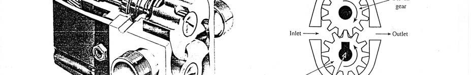
1 Contents 1- Introduction. - Pumps. Chapter Four Hydraulic Machines (لفرع الميكانيك العام فقط ( Turbines Cavitation in hydraulic machines. 5- Examples. 6- Problems; sheet No. 4 (Pumps) 7- Problems; sheet No. 4 (Turbines) 1- Introduction: There are two basic types of hydraulic machines: - Pumps: these machines add energy to fluids. - Turbines: these machines convert the fluid energy into useful mechanical work. - Pumps: Pumps are used to convert mechanical energy to fluid energy. In most of the cases pumps are used for raising fluids from a lower to a higher level. This is achieved by creating a low pressure at the inlet or suction end and high pressure at the outlet or delivery end of the pump. Classification of pumps: a- Positive displacement pumps. (figures (1) through (3)) b- Rotodynamic or (dynamic pressure pumps). (figures (4) and (5)) - Centrifugal pump. - Axial pump. - mixed flow pump.
2
3
4 Centrifugal pump: Consider the impeller of a centrifugal pump shown in figure, friction is neglected and the relative velocity of the fluid is always tangent to the blade. OR Where V absolute fluid velocity. W relative fluid velocity. u peripheral velocity of the impeller. α angle between u and V. β blade angle. For pump, the moment-of-momentum equation is: T ρ Q rv t rv [( ) ( ) ] out where T is the torque acting on the fluid. T ρq( rv cosα r1v 1 cosα1 ) t in
5 The power is: Power ρq u V cosα u1v1 cosα 1 ( ) The theoretical pump head is: uv cosα u1v1 cosα1 H th g The hydraulic (or manometric) efficiency of the pump: H act ηh H where th H act H th H losses The hydraulic losses (H losses ) include shock loss, fluid friction loss, and loss due to circulatory flow. Overall efficiency: γqh η act Tω In addition to hydraulic losses, the efficiency of a pump is reduced by bearing and packing friction and by disk friction as well as by the leakage effect. Head-Flow rate curves for centrifugal pumps: The maximum head produced by a centrifugal pump is called: Pump shutoff head (H o ). The equation for the (Q-H) curve can be written as: H H o -AQ where A costant
6 Operating point of a pump: The actual pump operating head and flow rate are determined by the intersection of the pump and system curves. It is important to select a pump such that the intersection of the pump and system curves is near the BEP.
7 Pumps operating in series and in parallel: The figures show the performance curves for two identical pumps in series and in parallel. - Pumps in series tend to increase the head (H). - Pumps in parallel tend to increase the flow rate (Q).
8 Similarity laws for centrifugal pumps: Flow rate similarity law: Q ND 3 m Q ND 3 p Head similarity law: gh N D m gh N D p Input power similarity law: power 3 5 ρn D m power 3 5 ρn D p Overall efficiency similarity law: η η m p where: p prototype ; m model ; N pump speed ; D impeller dia. Specific speed (N s ): In SI system: where N in (rad/s) Q in (m 3 /s) g in (m/s ) H in (m) N s ( SI) N Q 3 ( gh )4 In the US customary system: where N in (rpm) Q in (gpm) H in (ft) N s ( US) N H Q 3 4 The conversion factor between them is: N ( US) 730N ( SI) s s Also: N ( Eur) s N ( US) s The specific speed of a series is usually defined for the point of best efficiency (BEP).
9 3- Turbines:
10 4- Cavitation in hydraulic machines: When a liquid flows into a region where its pressure is reduced to vapor pressure, it boils and vapor pockets develop in it. The vapor bubbles are carried along with the liquid until a region of higher pressure is reached, where they suddenly collapse. This process is called cavitation. Cavitation parameter (σ): Turbine Pump patm pv γz s γhlosses σ cavitation parameter γh where: p atm atmospheric pressure. p υ absolute vapor pressure. Z s as shown in above figures. H net head across the machine. For cavitation not to occur at (1) the pressure must be greater than the vapor pressure of the liquid. or σ σ c where σ c is the critical cavitation parameter. Net Positive Suction Head (NPSH): patm pv γz s γhlosses ( NPSH ) A γ where (NPSH) A available net positive suction head.
11 Pump manufacturers specify a required value of net positive suction head (NPSH) R. To avoid cavitation: ( NPSH ) ( NPSH ) A R 5- Examples: 1- A centrifugal pump impeller has an outside diameter of 00 mm and rotates at 900 rpm. Determine the actual head generated if the vanes angle at outlet is 5 o and the radial component of flow velocity is constant through out the impeller is 3 m/s. Assume hydraulic efficiency as 75%. Solution: πdn u m/s 60 uv cosα uvt H g g V t u Vr tan β from equation (*) 3.94 m/s H m 9.81 H act ηh H th H m act (*) (Ans) - Solution:
12 University of Technology Sheet No. 4 Mechanical Engineering Dep. Pumps Fluid Mechanics II (3 rd year) 008/ A centrifugal water pump has an impeller with d 1 0. m, d 0.6 m, β 1 0 o, β 10 o, b 1 50 mm, b 19 mm. For 1800 rpm, neglecting losses and blade thickness, determine: a- the discharge for shock less entrance when α 1 90 o. b- α and H th. c- the power required. d- the pressure rise through the impeller. [0.16 m 3 /s ; o ; 19 m ; 73.4 kw ; 1030 kn/m ] - A centrifugal water pump with impeller diameters d 1 10 mm, d 54 mm, and b mm, b 38.1 mm, β 60 o is to pump 0.14 m 3 /s at 19.5 m head. Determine: β 1, the speed, and the power. Neglect losses and assume no shock at the entrance (α 1 90 o ). [43.56 o ; 1146 rpm ; 7. kw] 3- The impeller of centrifugal pump has an outer diameter of 5 cm and an effective outlet area of 170 cm. The blades are bent backward so that the direction of the outlet relative velocity makes an angle of 148 o with the tangent drawn in the direction of impeller rotation. The diameters of the suction and delivery pipes are 15 cm and 10 cm respectively. The pump delivers 1860 l/min at 1450 rpm. The gauge points on the suction and delivery pipes close to the pump show heads of 4.6 m below and 18 m above atmosphere respectively. The head losses in the suction and delivery pipes are m and.9 m respectively. Find the manometric efficiency assuming that water enters the pump without shock and whirl. [75%] 4- A three-stages centrifugal pump has impeller 40 cm in diameter and cm wide. If the blade angle at outlet is 45 o and the area occupied by the thickness of the vanes may be assumed 8% of the outlet area. If the pump delivers 3.6 m 3 /min when running at 90 rpm, Calculate: a- power of the pump. b- the head. c- specific speed. Assume mechanical efficiency as 88% and manometric efficiency as 77%. [65.75 kw ; m ; N s (U.S)1033] 5- Tests of a 0.57 m diameter centrifugal water pump at 134 rpm yield the following data: Q (m 3 /s) H (m) Power (kw) What is the BEP? What is the specific speed? Estimate the maximum discharge possible. [0.16 m 3 /s ; N s (U.S)141] 6- A pump with a critical value of σ of 0. is to pump against a head of 0 m. The barometric pressure is 98.5 kpa abs, and the vapor pressure is 5. kpa abs. Friction losses from the reservoir to the pump are 0.5 m. Find the maximum allowable height of the pump relative to the water surface in the reservoir. [no more than 5 m]
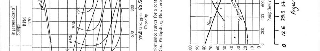
13 7- A centrifugal pump is installed above an open water tank. The pump is to provide a flow rate of m 3 /s. Under this flow condition, the pump manufacturer specifies (NPSH) R of 5 m. Determine the maximum elevation that the pump can be installed above the water free surface without pump cavitation. The head loss h l in the 100 mm dia. suction pipeline is due to a pump inlet strainer having a loss coefficient of 15. Other head losses are negligibly small, p atm 101 kpa, p υ.3 kpa. [no more than.8 m] 8- A centrifugal pump with a 91.5 cm impeller dia. operates at 800 rpm. If the speed is to be increased to 100 rpm, determine the impeller diameter that should be used so that the same shaft input power would be required. [71.7 cm] 9- A 30 cm diameter centrifugal water pump is geometrically similar to a 38 cm diameter pump. The larger pump has the following test performance characteristics at the best efficiency point: speed800 rpm, pump head15 m, flow rate0.16 m 3 /s, eff.80%, input shaft power3.6 kw. Determine the following for the smaller pump operating with water at 1000 rpm: a- flow rate, b- pump head, c- input power, d- maximum efficiency. [ m 3 /s ; 14.6 m ; kw ; 80%] 10- The 330 mm dia. centrifugal pump whose performance curves for water are given in figure (1) has been selected to operate in the fluid system of figure (). The following data are given for this system: Pipe dia mm Total pipe length 91.5 m Suction pipe length 7.6 m Pipe friction factor 0.03 Loss coefficients (K strainer +K 1 elbow ) 3 and (K valve +K elbow ) 1.5 Elevation difference (Z -Z 1 ) 4.6 m Elevation difference (Z 3 -Z 1 ) 1.55 m Determine:_ a- the pump flow rate. b- the pump efficiency. c- whether or not the selected pump is suitable for this application. (take: p atm 101 kpa, p υ.3 kpa) d- the input power required to drive the pump. [ m 3 /s ; 74% ; suitable ; 10.5 kw]
14 11- A centrifugal pump has the following approximate expression for the characteristic curve: H Q where H in (m) and Q in (m 3 /s). Find the discharge through the system of figure for two pumps in parallel. (Note: minor losses in the system can be neglected). [0.54 m 3 /s] 1- Find the discharge through the system shown in figure of problem (11) for pumps A and B in series; (L1600 m, d 300 mm, H 30 m, f 0.0). Neglect minor losses in the system. [79.5 l/s] Pump A: Q (l/s) H (m) Pump B: Q (l/s) H (m) * Approximate expressions for the characteristic curves: Pump A: H Q Pump B: H Q where H in (m) and Q in (m 3 /s).
15
Chapter Four Hydraulic Machines
 Contents 1- Introduction. 2- Pumps. Chapter Four Hydraulic Machines (لفرع الميكانيك العام فقط ( Turbines. -3 4- Cavitation in hydraulic machines. 5- Examples. 6- Problems; sheet No. 4 (Pumps) 7- Problems;
CHAPTER EIGHT P U M P I N G O F L I Q U I D S
 CHAPTER EIGHT P U M P I N G O F L I Q U I D S Pupmps are devices for supplying energy or head to a flowing liquid in order to overcome head losses due to friction and also if necessary, to raise liquid
Department of Civil and Environmental Engineering CVNG 1001: Mechanics of Fluids
 INTRODUCTION Hydrodynamic Machines A hydromachine is a device used either for extracting energy from a fluid or to add energy to a fluid. There are many types of hydromachines and Figure 1 below illustrates
CHAPTER TWO CENTRIFUGAL PUMPS 2.1 Energy Transfer In Turbo Machines
 7 CHAPTER TWO CENTRIFUGAL PUMPS 21 Energy Transfer In Turbo Machines Fig21 Now consider a turbomachine (pump or turbine) the total head (H) supplied by it is The power delivered to/by the fluid simply
Centrifugal Machines Table of Contents
 NLNG Course 017 Table of Contents 1 Introduction and Basic Principles... 1.1 Hydraulic Machines... 1.... 1.3 Pump Geometry... 1.4 Pump Blade Geometry...3 1.5 Diffusers...5 1.6 Pump Losses...6 1.7 Example
CIVE HYDRAULIC ENGINEERING PART II Pierre Julien Colorado State University
 1 CIVE 401 - HYDRAULIC ENGINEERING PART II Pierre Julien Colorado State University Problems with and are considered moderate and those with are the longest and most difficult. In 2018 solve the problems
Department of Energy Fundamentals Handbook. THERMODYNAMICS, HEAT TRANSFER, AND FLUID FLOW, Module 3 Fluid Flow
 Department of Energy Fundamentals Handbook THERMODYNAMICS, HEAT TRANSFER, AND FLUID FLOW, Module 3 REFERENCES REFERENCES Streeter, Victor L., Fluid Mechanics, 5th Edition, McGraw-Hill, New York, ISBN 07-062191-9.
BASIC EQUATION. Rotational speed. u = linear velocity in m/s r = radius in m ω = angular velocity in rad/s D = diameter in m N = rotation per minute
 CENTRIFUGAL PUMP BASIC EQUATION Rotational speed u = rω = πdn 60 u = linear velocity in m/s r = radius in m ω = angular velocity in rad/s D = diameter in m N = rotation per minute Power Power = F V = P
Applied Fluid Mechanics
 Applied Fluid Mechanics 1. The Nature of Fluid and the Study of Fluid Mechanics 2. Viscosity of Fluid 3. Pressure Measurement 4. Forces Due to Static Fluid 5. Buoyancy and Stability 6. Flow of Fluid and
ME 316: Thermofluids Laboratory
 ME 316 Thermofluid Laboratory 6.1 KING FAHD UNIVERSITY OF PETROLEUM & MINERALS ME 316: Thermofluids Laboratory PELTON IMPULSE TURBINE 1) OBJECTIVES a) To introduce the operational principle of an impulse
Introduction to Fluid Machines (Lectures 49 to 53)
") Introduction to Fluid Machines (Lectures 49 to 5) Q. Choose the crect answer (i) (ii) (iii) (iv) A hydraulic turbine rotates at N rpm operating under a net head H and having a discharge Q while developing
Introduction to Fluid Machines (Lectures 49 to 5) Q. Choose the crect answer (i) (ii) (iii) (iv) A hydraulic turbine rotates at N rpm operating under a net head H and having a discharge Q while developing
Pumping Stations Design For Infrastructure Master Program Engineering Faculty-IUG
 umping Stations Design For Infrastructure Master rogram Engineering Faculty-IUG Lecture : umping Hydraulics Dr. Fahid Rabah Water and environment Engineering frabah@iugaza.edu The main items that will
CHAPTER 12 Turbomachinery
 CAER urbomachinery Chapter / urbomachinery 800 / 0 8 8 rad /s, u r 8 8 0 0 m /s, u r 8 8 0 0 8 m /s, rbv, but V u since, n n 0 0 0 0 0 0 m / s V V 0 0 m /s, rb 0 0 0 Vn u 0 8 6 77 m /s, tan tan 0 n t V
BASIC EQUATION. Rotational speed = = ABC 60
 CENTRIFUGAL PUMP BASIC EQUATION Rotational speed = =?@ = ABC 60 = = linear velocity in m/s? = radius in m @ = angular velocity in rad/s B = diameter in m C = rotation per minute Power OPQR? = S U = O V
Theory of turbo machine Effect of Blade Configuration on Characteristics of Centrifugal machines. Unit 2 (Potters & Wiggert Sec
 Theory of turbo machine Effect of Blade Configuration on Characteristics of Centrifugal machines Unit (Potters & Wiggert Sec. 1..1, &-607) Expression relating Q, H, P developed by Rotary machines Rotary
9. Pumps (compressors & turbines) Partly based on Chapter 10 of the De Nevers textbook.
 Partly based on Chapter 10 of the De Nevers textbook.") Lecture Notes CHE 31 Fluid Mechanics (Fall 010) 9. Pumps (compressors & turbines) Partly based on Chapter 10 of the De Nevers textbook. Basics (pressure head, efficiency, working point, stability) Pumps
Lecture Notes CHE 31 Fluid Mechanics (Fall 010) 9. Pumps (compressors & turbines) Partly based on Chapter 10 of the De Nevers textbook. Basics (pressure head, efficiency, working point, stability) Pumps
CE 6403 APPLIED HYDRAULIC ENGINEERING UNIT - V PUMPS
 CE 6403 APPLIED HYDRAULIC ENGINEERING UNIT - V PUMPS Centrifugal pups - Miniu speed to start the pup - NPSH - Cavitations in pups Operating characteristics - Multistage pups - Reciprocating pups - Negative
mywbut.com Hydraulic Turbines
 Hydraulic Turbines Hydro-electric power accounts for up to 0% of the world s electrical generation. Hydraulic turbines come in a variety of shapes determined by the available head and a number of sizes
Chapter Four fluid flow mass, energy, Bernoulli and momentum
 4-1Conservation of Mass Principle Consider a control volume of arbitrary shape, as shown in Fig (4-1). Figure (4-1): the differential control volume and differential control volume (Total mass entering
Dr. S. Ramachandran Prof. R. Devaraj. Mr. YVS. Karthick AIR WALK PUBLICATIONS
 Fluid Machinery As per Revised Syllabus of Leading Universities including APJ ABDUL KALAM TECHNOLOGICAL UNIVERSITY Dr. S. Ramachandran Prof. R. Devaraj Professors School of Mechanical Engineering Sathyabama
SUMMER 14 EXAMINATION
 Important Instructions to examiners: 1) The answers should be examined by key words and not as word-to-word as given in the model answer scheme. 2) The model answer and the answer written by candidate
ISO 9906 INTERNATIONAL STANDARD. Rotodynamic pumps Hydraulic performance acceptance tests Grades 1 and 2
 INTERNATIONAL STANDARD ISO 9906 First edition 1999-1-15 Rotodynamic pumps Hydraulic performance acceptance tests Grades 1 and Pompes rotodynamiques Essais de fonctionnement hydraulique pour la réception
M E 320 Professor John M. Cimbala Lecture 23
 M E 320 Professor John M. Cimbala Lecture 23 Today, we will: Discuss diffusers and do an example problem Begin discussing pumps, and how they are analyzed in pipe flow systems D. Diffusers 1. Introduction.
1) Specific Gravity It is the ratio of specific weight of fluid to the specific weight of water.
 Specific Gravity It is the ratio of specific weight of fluid to the specific weight of water.") Important Instructions to examiners: 1) The answers should be examined by key words and not as word-to-word as given in the model answer scheme. 2) The model answer and the answer written by candidate
Important Instructions to examiners: 1) The answers should be examined by key words and not as word-to-word as given in the model answer scheme. 2) The model answer and the answer written by candidate
Chapter 7. Introduction to Fluid Machinery
 Chapter 7 Introduction to Fluid Machinery 1 Classification of Fluid Machines Positive diplacement machines (static type) Turbomachines (dynamic type) Turbines: extract energy to the flow :the fluid does
Hydraulic (Piezometric) Grade Lines (HGL) and
 Grade Lines (HGL) and") Hydraulic (Piezometric) Grade Lines (HGL) and Energy Grade Lines (EGL) When the energy equation is written between two points it is expresses as in the form of: Each term has a name and all terms have
Hydraulic (Piezometric) Grade Lines (HGL) and Energy Grade Lines (EGL) When the energy equation is written between two points it is expresses as in the form of: Each term has a name and all terms have
TOTAL HEAD, N.P.S.H. AND OTHER CALCULATION EXAMPLES Jacques Chaurette p. eng., June 2003
 TOTAL HEAD, N.P.S.H. AND OTHER CALCULATION EXAMPLES Jacques Chaurette p. eng., www.lightmypump.com June 2003 Figure 1 Calculation example flow schematic. Situation Water at 150 F is to be pumped from a
Introduction to Fluid Machines, and Compressible Flow Prof. S. K. Som Department of Mechanical Engineering Indian Institute of Technology, Kharagpur
 Introduction to Fluid Machines, and Compressible Flow Prof. S. K. Som Department of Mechanical Engineering Indian Institute of Technology, Kharagpur Lecture - 09 Introduction to Reaction Type of Hydraulic
Pressure and Flow Characteristics
 Pressure and Flow Characteristics Continuing Education from the American Society of Plumbing Engineers August 2015 ASPE.ORG/ReadLearnEarn CEU 226 READ, LEARN, EARN Note: In determining your answers to
ENERGY TRANSFER BETWEEN FLUID AND ROTOR. Dr. Ir. Harinaldi, M.Eng Mechanical Engineering Department Faculty of Engineering University of Indonesia
 ENERGY TRANSFER BETWEEN FLUID AND ROTOR Dr. Ir. Harinaldi, M.Eng Mechanical Engineering Department Faculty of Engineering University of Indonesia Basic Laws and Equations Continuity Equation m m ρ mass
Lecture on Francis Turbine. by Dr. Shibayan Sarkar Department of Mechanical Engg Indian Institute of Technology (ISM), Dhanbad
, Dhanbad") Lecture on Francis Turbine by Dr. Shibayan Sarkar Department of Mechanical Engg Indian Institute of Technology (ISM), Dhanbad Turbines: Francis (1849) di, Qo Ri ɵ Ra Stay ring Spiral casing π Q = v d 4
Lecture on Francis Turbine by Dr. Shibayan Sarkar Department of Mechanical Engg Indian Institute of Technology (ISM), Dhanbad Turbines: Francis (1849) di, Qo Ri ɵ Ra Stay ring Spiral casing π Q = v d 4
Chapter (6) Energy Equation and Its Applications
 Energy Equation and Its Applications") Chapter (6) Energy Equation and Its Applications Bernoulli Equation Bernoulli equation is one of the most useful equations in fluid mechanics and hydraulics. And it s a statement of the principle of conservation
Chapter (6) Energy Equation and Its Applications Bernoulli Equation Bernoulli equation is one of the most useful equations in fluid mechanics and hydraulics. And it s a statement of the principle of conservation
Homework 6. Solution 1. r ( V jet sin( θ) + ω r) ( ρ Q r) Vjet
 + ω r) ( ρ Q r) Vjet") Problem 1 Water enters the rotating sprinkler along the axis of rotation and leaves through three nozzles. How large is the resisting torque required to hold the rotor stationary for the angle that produces
Problem 1 Water enters the rotating sprinkler along the axis of rotation and leaves through three nozzles. How large is the resisting torque required to hold the rotor stationary for the angle that produces
Fluid Mechanics Answer Key of Objective & Conventional Questions
 019 MPROVEMENT Mechanical Engineering Fluid Mechanics Answer Key of Objective & Conventional Questions 1 Fluid Properties 1. (c). (b) 3. (c) 4. (576) 5. (3.61)(3.50 to 3.75) 6. (0.058)(0.05 to 0.06) 7.
by Dr. Shibayan Sarkar Department of Mechanical Engineering
 Lecture on Pump by Dr. Shibayan Sarkar Department of Mechanical Engineering Indian School of Mines Dhanbad WHAT IS PUMP? A hydrodynamic pump machine is a device which converts the mechanical energy held
4 Mechanics of Fluids (I)
") 1. The x and y components of velocity for a two-dimensional flow are u = 3.0 ft/s and v = 9.0x ft/s where x is in feet. Determine the equation for the streamlines and graph representative streamlines in
1. The x and y components of velocity for a two-dimensional flow are u = 3.0 ft/s and v = 9.0x ft/s where x is in feet. Determine the equation for the streamlines and graph representative streamlines in
ME 309 Fluid Mechanics Fall 2010 Exam 2 1A. 1B.
 Fall 010 Exam 1A. 1B. Fall 010 Exam 1C. Water is flowing through a 180º bend. The inner and outer radii of the bend are 0.75 and 1.5 m, respectively. The velocity profile is approximated as C/r where C
Specific Static rotor work ( P P )
") The specific Static Rotor ork p 1 ρ Specific Static rotor work ( P P ) here P, P static pressures at points, (P P ) static pressure difference of the rotor ρ density, in case of a compressible medium average
The specific Static Rotor ork p 1 ρ Specific Static rotor work ( P P ) here P, P static pressures at points, (P P ) static pressure difference of the rotor ρ density, in case of a compressible medium average
HYDRAULIC TURBINES. Hydraulics and Hydraulic Machines
 HYDRAULIC TURBINES Introduction: The device which converts h ydraulic energy into mechanical energy or vice versa is known as Hydraulic Machines. The h ydraulic machines which convert h ydraulic energy
Mechanical Engineering Programme of Study
 Mechanical Engineering Programme of Study Fluid Mechanics Instructor: Marios M. Fyrillas Email: eng.fm@fit.ac.cy SOLVED EXAMPLES ON VISCOUS FLOW 1. Consider steady, laminar flow between two fixed parallel
FLUID MECHANICS D203 SAE SOLUTIONS TUTORIAL 2 APPLICATIONS OF BERNOULLI SELF ASSESSMENT EXERCISE 1
 FLUID MECHANICS D203 SAE SOLUTIONS TUTORIAL 2 APPLICATIONS OF BERNOULLI SELF ASSESSMENT EXERCISE 1 1. A pipe 100 mm bore diameter carries oil of density 900 kg/m3 at a rate of 4 kg/s. The pipe reduces
CENTRIFUGAL PUMP SELECTION, SIZING, AND INTERPRETATION OF PERFORMANCE CURVES
 CENTRIFUGAL PUMP SELECTION, SIZING, AND INTERPRETATION OF PERFORMANCE CURVES 4.0 PUMP CLASSES Pumps may be classified in two general types, dynamic and positive displacement. Positive displacement pumps
Northern Lesson 2 Gear Pump Terminology. Gear Pump 101. Lesson 2: Gear Pump Terminology. When your reputation depends on it!
 Gear Pump 101 Lesson 2: Gear Pump Terminology When your reputation depends on it! Symbol Term Metric Unit Abbreviation US Customary Unit Abbreviation Conversion factor a A Area square millimeter mm2 square
MAHARASHTRA STATE BOARD OF TECHNICAL EDUCATION
 Important Instructions to examiners: 1) The answers should be examined by key words and not as word-to-word as given in the model answer scheme. 2) The model answer and the answer written by candidate
M E 320 Professor John M. Cimbala Lecture 24
 M E 30 Professor John M. Cimbala Lecture 4 Today, we will: Discuss pump performance curves Discuss how to match a pump and a piping system, and do some example problems. Pump Performance a. Pump performance
The following article was authored by Jacques Chaurette, President Fluide Design, Inc. (www.fluidedesign.com) All rights reserved.
 All rights reserved.") The following article was authored by Jacques Chaurette, President Fluide Design, Inc. (www.fluidedesign.com) All rights reserved. - HOW TO AVOID CAVITATION? CAVITATION CAN BE AVOIDED IF THE N.P.S.H. AVAILABLE
The following article was authored by Jacques Chaurette, President Fluide Design, Inc. (www.fluidedesign.com) All rights reserved. - HOW TO AVOID CAVITATION? CAVITATION CAN BE AVOIDED IF THE N.P.S.H. AVAILABLE
CHAPTER THREE FLUID MECHANICS
 CHAPTER THREE FLUID MECHANICS 3.1. Measurement of Pressure Drop for Flow through Different Geometries 3.. Determination of Operating Characteristics of a Centrifugal Pump 3.3. Energy Losses in Pipes under
Consider a control volume in the form of a straight section of a streamtube ABCD.
 6 MOMENTUM EQUATION 6.1 Momentum and Fluid Flow In mechanics, the momentum of a particle or object is defined as the product of its mass m and its velocity v: Momentum = mv The particles of a fluid stream
IJREAS Volume 2, Issue 2 (February 2012) ISSN:
 ISSN:") DESIGN AND CFD ANALYSIS OF SINGLE STAGE, END SUCTION, RADIAL FLOW CENTRIFUGAL PUMP FOR MINE DEWATERING APPLICATION Swapnil Urankar * Dr. H S Shivashankar ** Sourabh Gupta *** ABSTRACT Heavy centrifugal
DESIGN AND CFD ANALYSIS OF SINGLE STAGE, END SUCTION, RADIAL FLOW CENTRIFUGAL PUMP FOR MINE DEWATERING APPLICATION Swapnil Urankar * Dr. H S Shivashankar ** Sourabh Gupta *** ABSTRACT Heavy centrifugal
Hydraulic Turbines. Table 6.1 Parameters of hydraulic turbines. Power P (kw) Speed N (rpm)
 Speed N (rpm)") 6 Hydraulic Turbines Problem 1 There are 10 solved examples and 7 exercise problems (exclude Problems 1, 2, and 10) in this chapter. Prepare a table to mention the values of all the parameters, such as
6 Hydraulic Turbines Problem 1 There are 10 solved examples and 7 exercise problems (exclude Problems 1, 2, and 10) in this chapter. Prepare a table to mention the values of all the parameters, such as
CVE 372 HYDROMECHANICS EXERCISE PROBLEMS
 VE 37 HYDROMEHNIS EXERISE PROLEMS 1. pump that has the characteristic curve shown in the accompanying graph is to be installed in the system shown. What will be the discharge of water in the system? Take
Hydraulics. B.E. (Civil), Year/Part: II/II. Tutorial solutions: Pipe flow. Tutorial 1
, Year/Part: II/II. Tutorial solutions: Pipe flow. Tutorial 1") Hydraulics B.E. (Civil), Year/Part: II/II Tutorial solutions: Pipe flow Tutorial 1 -by Dr. K.N. Dulal Laminar flow 1. A pipe 200mm in diameter and 20km long conveys oil of density 900 kg/m 3 and viscosity
Hydraulics B.E. (Civil), Year/Part: II/II Tutorial solutions: Pipe flow Tutorial 1 -by Dr. K.N. Dulal Laminar flow 1. A pipe 200mm in diameter and 20km long conveys oil of density 900 kg/m 3 and viscosity
Institute of Aeronautical Engineering
 Institute of Aeronautical Engineering Hydraulics & Hydraulic Machinery (ACE011) R16 B.Tech III Year V Semester Prepared by Dr. G. Venkata Ramana Professor& HOD Civil Engineering 1 Unit I OPEN CHANNEL FLOW
Introduction to Fluid Machines and Compressible Flow Prof. S. K. Som Department of Mechanical Engineering Indian Institute of Technology, Kharagpur
 Introduction to Fluid Machines and Compressible Flow Prof. S. K. Som Department of Mechanical Engineering Indian Institute of Technology, Kharagpur Lecture - 1 Introduction to Fluid Machines Well, good
Introduction to Fluid Machines and Compressible Flow Prof. S. K. Som Department of Mechanical Engineering Indian Institute of Technology, Kharagpur
 Introduction to Fluid Machines and Compressible Flow Prof. S. K. Som Department of Mechanical Engineering Indian Institute of Technology, Kharagpur Lecture - 07 Analysis of Force on the Bucket of Pelton
Experimental and Numerical Investigations of the Effect of Net Positive Suction Head on Water Hammer In Pipeline Systems
 International Journal of Engineering and Advanced Technology (IJEAT) ISSN: 2249 8958, Volume-3, Issue-1, October 2013 Experimental and Numerical Investigations of the Effect of Net Positive Suction Head
(Refer Slide Time: 4:41)
") Fluid Machines. Professor Sankar Kumar Som. Department Of Mechanical Engineering. Indian Institute Of Technology Kharagpur. Lecture-30. Basic Principle and Energy Transfer in Centrifugal Compressor Part
Fluid Machines. Professor Sankar Kumar Som. Department Of Mechanical Engineering. Indian Institute Of Technology Kharagpur. Lecture-30. Basic Principle and Energy Transfer in Centrifugal Compressor Part
FE Fluids Review March 23, 2012 Steve Burian (Civil & Environmental Engineering)
") Topic: Fluid Properties 1. If 6 m 3 of oil weighs 47 kn, calculate its specific weight, density, and specific gravity. 2. 10.0 L of an incompressible liquid exert a force of 20 N at the earth s surface.
Topic: Fluid Properties 1. If 6 m 3 of oil weighs 47 kn, calculate its specific weight, density, and specific gravity. 2. 10.0 L of an incompressible liquid exert a force of 20 N at the earth s surface.
Mass of fluid leaving per unit time
 5 ENERGY EQUATION OF FLUID MOTION 5.1 Eulerian Approach & Control Volume In order to develop the equations that describe a flow, it is assumed that fluids are subject to certain fundamental laws of physics.
Chapter 5 Control Volume Approach and Continuity Equation
 Chapter 5 Control Volume Approach and Continuity Equation Lagrangian and Eulerian Approach To evaluate the pressure and velocities at arbitrary locations in a flow field. The flow into a sudden contraction,
Exam #2: Fluid Kinematics and Conservation Laws April 13, 2016, 7:00 p.m. 8:40 p.m. in CE 118
 CVEN 311-501 (Socolofsky) Fluid Dynamics Exam #2: Fluid Kinematics and Conservation Laws April 13, 2016, 7:00 p.m. 8:40 p.m. in CE 118 Name: : UIN: : Instructions: Fill in your name and UIN in the space
Design of Monoblock Centrifugal Pump Impeller
 Design of Monoblock Centrifugal Pump Impeller Authors Mr. Chetan Kallappa Tambake 1, Prof. P. V. Salunke 1 Department of Mechanical Engineering, Walchand Institute of Technology, Ashok Chowk, Solapur-413006,
CONTENTS CHAPTER (II) DIMENSIONAL ANALYSIS AND SIMILITUDE OF TURBOMACHINES
 DIMENSIONAL ANALYSIS AND SIMILITUDE OF TURBOMACHINES") CONTENTS CHAPTER (I) BASIC THEORY Historical Review.............. General Introduction............ 4. Velocity Diagram.............. 5.3 Momentum Transfer Principles........ 6.4 Energy Equation..............
CONTENTS CHAPTER (I) BASIC THEORY Historical Review.............. General Introduction............ 4. Velocity Diagram.............. 5.3 Momentum Transfer Principles........ 6.4 Energy Equation..............
2 Internal Fluid Flow
 Internal Fluid Flow.1 Definitions Fluid Dynamics The study of fluids in motion. Static Pressure The pressure at a given point exerted by the static head of the fluid present directly above that point.
Optimizing Centrifugal Pump Performance by Different Blade Configuration Patterns
 American Journal of Mechanical and Industrial Engineering 2018; 3(1): 1-14 http://www.sciencepublishinggroup.com/j/ajmie doi: 10.11648/j.ajmie.20180301.11 ISSN: 2575-6079 (Print); ISSN: 2575-6060 (Online)
COMPUTER AIDED DESIGN OF RADIAL TIPPED CENTRIFUGAL BLOWERS AND FANS
 4 th International Conference on Mechanical Engineering, December 26-28, 21, Dhaka, Bangladesh/pp. IV 55-6 COMPUTER AIDED DESIGN OF RADIAL TIPPED CENTRIFUGAL BLOWERS AND FANS Nitin N. Vibhakar* and S.
Introduction to Turbomachinery
 1. Coordinate System Introduction to Turbomachinery Since there are stationary and rotating blades in turbomachines, they tend to form a cylindrical form, represented in three directions; 1. Axial 2. Radial
PumpTech Customer Education
 PumpTech Customer Education http://www.pumptechnw.com Bellevue Moses Lake Canby PumpTech Product Lines UL Listed Packaged Systems Two full time Mechanical Engineers Licensed in OR, WA & ID SolidWorks &
Basic Fluid Mechanics
 Basic Fluid Mechanics Chapter 5: Application of Bernoulli Equation 4/16/2018 C5: Application of Bernoulli Equation 1 5.1 Introduction In this chapter we will show that the equation of motion of a particle
Investigations on the Performance of Centrifugal Pumps In Conjunction With Inducers
 Investigations on the Performance of Centrifugal Pumps In Conjunction With Inducers Mohammed A. El Samanody, (1) Ashraf Ghorab (2 ) and Mamdouh A. Mostafa, (3) 1-Prof. of Hydropower & Fluid Mechanics,
Chapter 7 Energy Principle
 Chater 7: Energy Princile By Dr Ali Jawarneh Hashemite University Outline In this chater we will: Derive and analyse the Energy equation. Analyse the flow and shaft work. Derive the equation for steady
BME-A PREVIOUS YEAR QUESTIONS
 BME-A PREVIOUS YEAR QUESTIONS CREDITS CHANGE ACCHA HAI TEAM UNIT-1 Introduction: Introduction to Thermodynamics, Concepts of systems, control volume, state, properties, equilibrium, quasi-static process,
vector H. If O is the point about which moments are desired, the angular moment about O is given:
 The angular momentum A control volume analysis can be applied to the angular momentum, by letting B equal to angularmomentum vector H. If O is the point about which moments are desired, the angular moment
Rate of Flow Quantity of fluid passing through any section (area) per unit time
 per unit time") Kinematics of Fluid Flow Kinematics is the science which deals with study of motion of liquids without considering the forces causing the motion. Rate of Flow Quantity of fluid passing through any section
Kinematics of Fluid Flow Kinematics is the science which deals with study of motion of liquids without considering the forces causing the motion. Rate of Flow Quantity of fluid passing through any section
Conservation of Angular Momentum
 10 March 2017 Conservation of ngular Momentum Lecture 23 In the last class, we discussed about the conservation of angular momentum principle. Using RTT, the angular momentum principle was given as DHo
nozzle which is fitted to a pipe through which the liquid is flowing under pressure.
 Impact of Jets 1. The liquid comes out in the form of a jet from the outlet of a nozzle which is fitted to a pipe through which the liquid is flowing under pressure. The following cases of the impact of
COURSE NUMBER: ME 321 Fluid Mechanics I 3 credit hour. Basic Equations in fluid Dynamics
 COURSE NUMBER: ME 321 Fluid Mechanics I 3 credit hour Basic Equations in fluid Dynamics Course teacher Dr. M. Mahbubur Razzaque Professor Department of Mechanical Engineering BUET 1 Description of Fluid
where = rate of change of total energy of the system, = rate of heat added to the system, = rate of work done by the system
 The Energy Equation for Control Volumes Recall, the First Law of Thermodynamics: where = rate of change of total energy of the system, = rate of heat added to the system, = rate of work done by the system
SOE2156: Fluids Lecture 4
 Turbo SOE2156: s Lecture 4 machine { a device exchanging energy (work) between a uid and a mechanical system. In particular : a turbomachine is a device using a rotating mechanical system. The ow of energy
Signature: (Note that unsigned exams will be given a score of zero.)
") Neatly print your name: Signature: (Note that unsigned exams will be given a score of zero.) Circle your lecture section (-1 point if not circled, or circled incorrectly): Prof. Dabiri Prof. Wassgren Prof.
Neatly print your name: Signature: (Note that unsigned exams will be given a score of zero.) Circle your lecture section (-1 point if not circled, or circled incorrectly): Prof. Dabiri Prof. Wassgren Prof.
Contents. 2 Basic Components Aerofoils Force Generation Performance Parameters xvii
 Contents 1 Working Principles... 1 1.1 Definition of a Turbomachine... 1 1.2 Examples of Axial Turbomachines... 2 1.2.1 Axial Hydraulic Turbine... 2 1.2.2 Axial Pump... 4 1.3 Mean Line Analysis... 5 1.4
Fluid Mechanics II 3 credit hour. Fluid flow through pipes-minor losses
 COURSE NUMBER: ME 323 Fluid Mechanics II 3 credit hour Fluid flow through pipes-minor losses Course teacher Dr. M. Mahbubur Razzaque Professor Department of Mechanical Engineering BUET 1 Losses in Noncircular
Numerical Study of the Semi-Open Centrifugal Pump Impeller Side Clearance A. Farid Ayad *, H. M. Abdalla,A. S. Abo El-Azm Egyptian Armed Forces, Egypt
 16 th International Conference on AEROSPACE SCIENCES & AVIATION TECHNOLOGY, ASAT - 16 May 26-28, 2015, E-Mail: asat@mtc.edu.eg Military Technical College, Kobry Elkobbah, Cairo, Egypt Tel : +(202) 24025292
Chapter 4. Turbomachinery. 4.1 Introduction. 4.2 Pumps
 Chapter 4 Turbomachinery 4.1 Introduction In this chapter we will examine the performance characteristics of turbomachinery. The word turbo implies a spinning action is involved. In turbomachinery, a blade
CLASS Fourth Units (Second part)
") CLASS Fourth Units (Second part) Energy analysis of closed systems Copyright The McGraw-Hill Companies, Inc. Permission required for reproduction or display. MOVING BOUNDARY WORK Moving boundary work (P
CLASS Fourth Units (Second part) Energy analysis of closed systems Copyright The McGraw-Hill Companies, Inc. Permission required for reproduction or display. MOVING BOUNDARY WORK Moving boundary work (P
MASS, MOMENTUM, AND ENERGY EQUATIONS
 MASS, MOMENTUM, AND ENERGY EQUATIONS This chapter deals with four equations commonly used in fluid mechanics: the mass, Bernoulli, Momentum and energy equations. The mass equation is an expression of the
3 Energy Exchange in Turbomachines
 3 Energy Exchange in Turbomachines Problem 1 The solved and unsolved examples of this chapter are meant to illustrate the various forms of velocity triangles and the variety of the turbomachines. In addition,
Evaluation of pump characteristic from measurement of fast deceleration
 EPJ Web of Conferences 92, 02022 (2015) DOI: 10.1051/ epjconf/ 20159202022 C Owned by the authors, published by EDP Sciences, 2015 Evaluation of pump characteristic from measurement of fast deceleration
Lesson 6 Review of fundamentals: Fluid flow
 Lesson 6 Review of fundamentals: Fluid flow The specific objective of this lesson is to conduct a brief review of the fundamentals of fluid flow and present: A general equation for conservation of mass
THE APPLICATION OF THERMODYNAMICS TO PUMP SYSTEMS
 THE APPLICATION OF THERMODYNAMICS TO PUMP SYSTEMS.0 ENERGY AND THERMODYNAMIC PROPERTIES This chapter requires some introduction to thermodynamic properties and states. No need to panic, we will use only
Angular momentum equation
 Angular momentum equation For angular momentum equation, B =H O the angular momentum vector about point O which moments are desired. Where β is The Reynolds transport equation can be written as follows:
Objectives. Conservation of mass principle: Mass Equation The Bernoulli equation Conservation of energy principle: Energy equation
 Objectives Conservation of mass principle: Mass Equation The Bernoulli equation Conservation of energy principle: Energy equation Conservation of Mass Conservation of Mass Mass, like energy, is a conserved
5 ENERGY EQUATION OF FLUID MOTION
 5 ENERGY EQUATION OF FLUID MOTION 5.1 Introduction In order to develop the equations that describe a flow, it is assumed that fluids are subject to certain fundamental laws of physics. The pertinent laws
UNIFIED DESIGN AND COMPARATIVE PERFORMANCE EVALUATION OF FORWARD AND BACKWARD CURVED RADIAL TIPPED CENTRIFUGAL FAN
 Proceedings of the International Conference on Mechanical Engineering 3 (ICME3) 6-8 December 3, Dhaka, Bangladesh ICME3-FL- UNIFIED DESIGN AND COMPARATIVE PERFORMANCE EVALUATION OF FORWARD AND BACKWARD
Chapter 7 The Energy Equation
 Chapter 7 The Energy Equation 7.1 Energy, Work, and Power When matter has energy, the matter can be used to do work. A fluid can have several forms of energy. For example a fluid jet has kinetic energy,
Water Pumps and Pumping Systems
 Water Pumps and Pumping Systems By Dr. Mohammed med Haggag Lecture 1 Course Content Course Outlines 1. Introduction and objectives of the course.. Hydraulics of pumping systems: - Definitions - Estimation
Fluid Dynamics Midterm Exam #2 November 10, 2008, 7:00-8:40 pm in CE 110
 CVEN 311-501 Fluid Dynamics Midterm Exam #2 November 10, 2008, 7:00-8:40 pm in CE 110 Name: UIN: Instructions: Fill in your name and UIN in the space above. There should be 11 pages including this one.
INTERNAL FLOWS / FLOWS IN DUCTS
 Fluid and Particulate systems 4451 /018 INTERNAL FLOWS / FLOWS IN DUCTS Ron Zevenhoven ÅA Thermal and Flow Engineering ron.zevenhoven@abo.fi.1 Flow tube sections in series, in parallel, or branched RoNz
Pipe Flow. Lecture 17
 Pipe Flow Lecture 7 Pipe Flow and the Energy Equation For pipe flow, the Bernoulli equation alone is not sufficient. Friction loss along the pipe, and momentum loss through diameter changes and corners
CHAPTER 3 BASIC EQUATIONS IN FLUID MECHANICS NOOR ALIZA AHMAD
 CHAPTER 3 BASIC EQUATIONS IN FLUID MECHANICS 1 INTRODUCTION Flow often referred as an ideal fluid. We presume that such a fluid has no viscosity. However, this is an idealized situation that does not exist.