WATER DISTRIBUTION NETWORKS
|
|
|
- Mae Quinn
- 5 years ago
- Views:
Transcription
1 WATER DISTRIBUTION NETWORKS CE Components of Water Supply System 2 1
2 Water Distribution System Water distribution systems are designed to adequately satisfy the water requirements for a combinations of the following demands: Domestic Commercial Industrial Fire-fighting The system should be capable of meeting the demands at all times and at satisfactory pressure 3 Water Distribution System The main elements of the distribution system are: Pipe systems Pumping stations Storage facilities Fire hydrants House service connections Meters Other appurtenances 4 2
3 System Configurations Distribution systems may be classified as: Branching systems Grid systems A combination of the above two systems The configuration of the system is dictated by: Street patterns Topography Degree and type of development of the area Location of the treatment and storage works
4 System Configurations Branching vs. grid systems: A grid system is usually preferred over a branching system, since it can furnish a supply to any point from at least two directions The branching system has dead ends, therefore, does not permit supply from more than one direction. Should be avoided where possible. In locations where sharp changes in topography occur (hilly or mountainous areas), it is common practice to divide the distribution system into two or more service areas. 7 Basic System Requirements Pressure: Pressure should be great enough to adequately meet consumer and fire-fighting needs. Pressure should not be excessive: Cost consideration Leakage and maintenance increase Capacity: The capacity is determined on the bases of local water needs plus fire-fighting demand. Pipe sizes should be selected to avoid high velocities: Pipe sizes should selected based on flow velocity of 3-5 fps Where fire-fighting is required, minimum pipe diameter is 6 in. 8 4
5 Hydraulic Design The design flowrate is based on the maximum of the following two rates: Maximum day demand plus fire demand Maximum hourly rate Analysis of distribution system: Distribution system have series of pipes of different diameters. In order to simplify the analysis, skeletonizing is used. Skeletonizing is the replacement of a series of pipes of varying diameters with one equivalent pipe or replacing a system of pipes with one equivalent pipe. 9 Skeletonization 10 5
6 Hydraulic Design Example: Consider the piping system shown in the figure, replace (a) pipes BC and CD with an equivalent 12-in. pipe and (b) the system from B to D with an equivalent 20-in. pipe. Solution: a) for pipes in series: 1. assume any value for Q through BCD (8 cfs) 2. from nomograph with Q = 8 cfs and dia = 18-in, read head loss for BC = 6.1ft/1000ft 3. from nomograph with Q = 8 cfs and dia = 16-in, read head loss for CD = 11ft/1000ft 4. total head loss BD = (6.1/1000)*200+(11/1000)*500 = 6.72ft ft - 18 in. C 500 ft - 16 in. A B A D E Z 900 ft - 12 in. 12 6
7 Nomograph for Hazen Williams equation 13 Hydraulic Design 5. the total head loss for 12-in equivalent pipe at 8 cfs is 45ft/1000ft (from nomograph) 6. head loss BCD = head loss BD, therefore; 6.72ft = L eq * (45/1000) L eq = 6.72 * (1000/45) = 149 ft b) for pipes in parallel: 1. assume any value of head loss between BD (h L =5 ft) 2. for the equivalent pipe (L = 149 ft), head loss per 1000ft is; h L = (5/149)*1000 = 33.5ft/1000ft Diameter of equivalent pipe = 12-in Q eq = 6.8 cfs (from nomograph) 14 7
8 Hydraulic Design 3. for the 900 ft 12-in pipe: h L = (5/900)*1000 = 5.5ft/1000ft Q 900 = 2.6 cfs (from nomograph) 4. total flow = = 9.4 cfs 5. for Q = 9.4 cfs and 20-in pipe: head loss = 4.8ft/1000ft (nomograph) 6. head loss 12-in pipe = head loss 20-in pipe 5 ft = L * (4.8ft/1000ft) L = 5 * (1000/4.8) = 1042 ft 15 Hydraulic Design Pipe networks: Pipe networks are composed of a number of constant-diameter pipe sections containing pumps and fittings. From next figure, following are defined: Node: end of each pipe section. (A, B, C, D, E, F, G, and H) Junction node: points where pipes meet and where flow may be introduces or withdrawn. (B, C, D, E, F, and G) Fixed-grade nodes: points where constant grade is maintained. (A and B) Loops: closed pipe circuits. (1 and 2) From above terminology, we can write the following eq. P = J + L + F 1 Where: P = # pipes, J = # Junction node, L = #loops, F = # fixed-grade nodes 16 8
9 Pipe Network 17 Hydraulic Design Loop equations: Hydraulic performance of pipe networks are based on mass continuity and energy conservation. Continuity of mass: ΣQ in - ΣQ out = Q e (J number of equations) Q in = inflow into node Q out = outflow from node Q e = external flow into the system or withdrawal Conservation of energy: Σh L = ΣE p (L number of equations) h L = head loss; E p = pump head For fixed-grade nodes, the following can be written: E = Σh L - ΣE p (F-1 equations) 18 9
10 Hydraulic Design Loop equations: (continue) Frictional losses in pipes: h LP = K P Q n Where; K P = constant incorporating pipe size, its roughness, and units used n = an exponent The Hazen-Williams formula for head loss is given as: h LP = K P Q 1.85 Minor losses: These losses are due fittings, valves, meters, or other insertions that affect the flow. They are expressed as: h LM = K M Q 2 Where; K M = minor loss constant 19 Hydraulic Design Node equations: When considering nodes, the principle relationship used is the continuity equation: Q in -Q out = Q e The discharge in pipe ab can be expressed in terms of grade (head) as the following: h L = KQ n h Lab = h a h b = K ab Q n Or Q ab Q ab = {(h a -h b )/K ab } 1/n a b Q e 20 10
11 Hydraulic Design Node equations: If pump exist in the line, then junction nodes are specified at the inlet and outlet. for continuity: Q ab = Q cd {(h a -h b )/K ab } 1/n = {(h c -h d )/K cd } 1/n h a -h b = (K ab /K cd ) (h c h d ) The head change across pump is: h c h b = P(Q) P(Q) = is the head developed by the pump = (550 hp)/(γq) hp = horsepower, γ = weight of water, Q = flow 21 Distribution Reservoirs Definition: Distribution reservoirs provide service storage to meet the widely fluctuating demands often imposed on the distribution system, to accommodate fire-fighting and emergency requirements, and to equalize operating pressure. Types of reservoirs: Surface reservoir Usually lined with concrete, gunite, asphalt, or membrane. They may be covered or uncovered, but usually covered to prevent contamination. Standpipes or elevated tanks Normally employed where the construction of a surface reservoir would not provide sufficient head. Stand pipes are tall cylindrical tanks whose storage volume includes an upper portion (useful storage) and a lower portion (supporting storage)

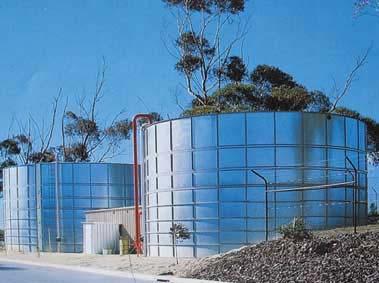
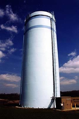
12 Surface Reservoir 23 Standpipes 24 12


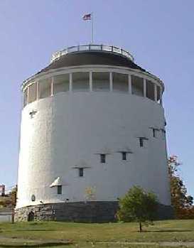
13 Elevated tanks 25 Distribution Reservoirs Location Distribution reservoirs should be located strategically for maximum benefits. Normally the reservoir should be near the center of use. For large areas, a number of reservoirs may be located at key locations A central location decreases the friction losses by reducing the distance to the serviced area. Storage function To provide head required head. To provide excess demand such as: fire-fighting: should be sufficient to provide flow for hours. emergency demands: to sustain the demand during failure of the supply system and times of maintenance. To provide equalization storage
14 27 Pumping Introduction Pumping is an important part of the transportation and distribution system. Requirements vary from small units (few gallons per minute) to large units (several hundred cubic feet per second) Two kinds of pumping equipments are mainly used; centrifugal and displacement pumps. Types of pumps Low-lift pumps: used to lift water from a source to the treatment plant High-service pumps: used to discharge water under pressure to the distribution system Booster pumps: used to increase pressure in the distribution system. Recirculation pumps: used within a treatment plant. Well pumps: used to left water from wells


15 Centrifugal pumps Used to lift and transport water Widely used in water and wastewater applications due to: Simplicity of installation and operation. Compactness. Low cost compared to others. Operate under variety of conditions How do they operate: On the principle of centrifugal force; force of pushing outwards. The impeller driven at high speed throws water into the casing Water is channeled through a nozzle to the discharge piping


16 31 Centrifugal pumps Pumping head The pump operates against a certain head called Total Dynamic Head (TDH). TDH is composed of the following: The difference in elevation between the pump centerline and the elevation to which the water is to be raised. The difference in elevation between the level of the suction pool and the pump centerline The friction losses Velocity head TDH = H L + H F + H V Where; H L = total static head H F = total friction head H V = velocity head (V 2 /2g) 32 16
17 33 Centrifugal pumps Power The theoretical horsepower required may be found by using the following equation: hp = QγH/550 Where; Q = discharge, cfs γ = specific weight of water, 62.4 lb/ft 3 H = total dynamic head, ft The actual hp required is obtained by dividing the theoretical hp by the efficiency of the pump
18 Centrifugal pumps System head The system head is represented by a plot of TDH vs. discharge for the system being studied. The plot is used to help in selecting the pumping unit. The system head curve will vary with flow since H F and H V are both a function of discharge. Since the static head H L may vary as a result of fluctuating water levels, it is necessary to plot system head curves covering the range of variations in static head
19 Centrifugal pumps Pump characteristics Each pump has its own characteristics relative to power requirements, efficiency, and head developed as a function of rate of flow. These relationships are usually given as a set of pump characteristic curves for a specified speed. Pump characteristic curves are used in conjunction with system-head curves to select suitable pumping equipment for a particular installation. As the flow of the centrifugal pump increases, the head will fall. At maximum efficiency, the discharge is known as normal or rated discharge. To change the flow, the practical and efficient approach is to provide two or more pumps in parallel so that the flow may be carried at close to the peak efficiency. The normal range of efficiency is between 50-85%
20 39 Centrifugal pumps Selection of pumping units Normally the engineer is given the system-head characteristics curve and is required to find a pump or pumps to deliver the required flow. The system-head curve is plotted with the pump characteristics curve. The operating point is located at the intersection of the system-head curve and the pump characteristics curve. This point gives the head and flow at which the pump will be operating. A pump should be selected so that the operating point is also as close as possible to peak efficiency. Pumps connected in series; the total head equals the sum of the heads added by each pump (discharge stay constant). Pumps connected in parallel; the total discharge is the sum of the discharges of each pump at a given head (head stay constant)
21 21 41
Pumping Stations Design For Infrastructure Master Program Engineering Faculty-IUG
 umping Stations Design For Infrastructure Master rogram Engineering Faculty-IUG Lecture : umping Hydraulics Dr. Fahid Rabah Water and environment Engineering frabah@iugaza.edu The main items that will
CVE 372 HYDROMECHANICS EXERCISE PROBLEMS
 VE 37 HYDROMEHNIS EXERISE PROLEMS 1. pump that has the characteristic curve shown in the accompanying graph is to be installed in the system shown. What will be the discharge of water in the system? Take
Fluids Engineering. Pipeline Systems 2. Course teacher Dr. M. Mahbubur Razzaque Professor Department of Mechanical Engineering BUET
 COURSE NUMBER: ME 423 Fluids Engineering Pipeline Systems 2 Course teacher Dr. M. Mahbubur Razzaque Professor Department of Mechanical Engineering BUET 1 SERIES PIPE FLOW WITH PUMP(S) 2 3 4 Colebrook-
Exam #1. A. Answer any 1 of the following 2 questions. CEE 371 October 8, Please grade the following questions: 1 or 2
 CEE 37 October 8, 009 Exam # Closed Book, one sheet of notes allowed Please answer one question from the first two, one from the second two and one from the last three. The total potential number of points
PUMP PERFORMANCE MEASUREMENTS Jacques Chaurette p. eng. April 2003
 PUMP PERFORMANCE MEASUREMENTS Jacques Chaurette p. eng. www.lightmypump.com April 003 Synopsis This article examines how to take flow and pressure measurement and then calculate the total head of a pump
Analysis Methods for Water Distribution Systems-3 rd Class )طرق تحليل أنظمة توزيع المياه( Dr. Sataa A. Al-Bayati (10-11)
طرق تحليل أنظمة توزيع المياه( Dr. Sataa A. Al-Bayati (10-11)") تسم هللا الزحمه الزحيم Analysis Methods for Water Distribution Systems-3 rd Class )طرق تحليل أنظمة توزيع المياه( Dr. Sataa A. Al-Bayati (10-11) Methods of analysis are: )المقاطغ( Sectioning.1 )االوثىب
تسم هللا الزحمه الزحيم Analysis Methods for Water Distribution Systems-3 rd Class )طرق تحليل أنظمة توزيع المياه( Dr. Sataa A. Al-Bayati (10-11) Methods of analysis are: )المقاطغ( Sectioning.1 )االوثىب
Pressure and Flow Characteristics
 Pressure and Flow Characteristics Continuing Education from the American Society of Plumbing Engineers August 2015 ASPE.ORG/ReadLearnEarn CEU 226 READ, LEARN, EARN Note: In determining your answers to
TOTAL HEAD, N.P.S.H. AND OTHER CALCULATION EXAMPLES Jacques Chaurette p. eng., June 2003
 TOTAL HEAD, N.P.S.H. AND OTHER CALCULATION EXAMPLES Jacques Chaurette p. eng., www.lightmypump.com June 2003 Figure 1 Calculation example flow schematic. Situation Water at 150 F is to be pumped from a
Basic Math Concepts for Water and Wastewater Operators. Daniel B. Stephens & Associates, Inc.
 Basic Math Concepts for Water and Wastewater Operators Topics Hierarchy of operations Manipulating equations Unit/dimensional analysis and conversion factors Electricity Temperature Geometry Flow hydraulics
Pressure Head: Pressure head is the height of a column of water that would exert a unit pressure equal to the pressure of the water.
 Design Manual Chapter - Stormwater D - Storm Sewer Design D- Storm Sewer Sizing A. Introduction The purpose of this section is to outline the basic hydraulic principles in order to determine the storm
FLOW FRICTION CHARACTERISTICS OF CONCRETE PRESSURE PIPE
 11 ACPPA TECHNICAL SERIES FLOW FRICTION CHARACTERISTICS OF CONCRETE PRESSURE PIPE This paper presents formulas to assist in hydraulic design of concrete pressure pipe. There are many formulas to calculate
Applied Fluid Mechanics
 Applied Fluid Mechanics 1. The Nature of Fluid and the Study of Fluid Mechanics 2. Viscosity of Fluid 3. Pressure Measurement 4. Forces Due to Static Fluid 5. Buoyancy and Stability 6. Flow of Fluid and
Chapter (3) Water Flow in Pipes
 Water Flow in Pipes") Chapter (3) Water Flow in Pipes Water Flow in Pipes Bernoulli Equation Recall fluid mechanics course, the Bernoulli equation is: P 1 ρg + v 1 g + z 1 = P ρg + v g + z h P + h T + h L Here, we want to study
Chapter (3) Water Flow in Pipes Water Flow in Pipes Bernoulli Equation Recall fluid mechanics course, the Bernoulli equation is: P 1 ρg + v 1 g + z 1 = P ρg + v g + z h P + h T + h L Here, we want to study
STEADY FLOW THROUGH PIPES DARCY WEISBACH EQUATION FOR FLOW IN PIPES. HAZEN WILLIAM S FORMULA, LOSSES IN PIPELINES, HYDRAULIC GRADE LINES AND ENERGY
 STEADY FLOW THROUGH PIPES DARCY WEISBACH EQUATION FOR FLOW IN PIPES. HAZEN WILLIAM S FORMULA, LOSSES IN PIPELINES, HYDRAULIC GRADE LINES AND ENERGY LINES 1 SIGNIFICANCE OF CONDUITS In considering the convenience
Chapter (3) Water Flow in Pipes
 Water Flow in Pipes") Chapter (3) Water Flow in Pipes Water Flow in Pipes Bernoulli Equation Recall fluid mechanics course, the Bernoulli equation is: P 1 ρg + v 1 g + z 1 = P ρg + v g + z h P + h T + h L Here, we want to study
Chapter (3) Water Flow in Pipes Water Flow in Pipes Bernoulli Equation Recall fluid mechanics course, the Bernoulli equation is: P 1 ρg + v 1 g + z 1 = P ρg + v g + z h P + h T + h L Here, we want to study
Analysis of Complex Pipe Networks with Multiple Loops and Inlets and Outlets
 Analysis of Complex Pipe Networks with Multiple Loops and Inlets and Outlets The techniques described previously for analysis of pipe flow are satisfactory if the pipe system is simple, consisting of one
3301 East 120 th Avenue Assited Living & Memory Care
 UTILITY REPORT FOR 3301 East 120 th Avenue Assited Living & Memory Care 1 st Submittal January 23, 2016 2 nd Submittal March 04, 2016 Prepared for: 3301 E. 120 th Ave, LLC. 8200 E. Maplewood Ave., Suite
spatial water demand (population density) spatial junctions distribution (building density) digital elevation map
 spatial junctions distribution (building density) digital elevation map") SYSTEM ID: WDS-Designer NARRATIVE DESCRIPTION With the WDS Designer a tool for the algorithmic generation of synthetic water distribution systems (swds) based on GIS data was presented (Sitzenfrei et al.,
SYSTEM ID: WDS-Designer NARRATIVE DESCRIPTION With the WDS Designer a tool for the algorithmic generation of synthetic water distribution systems (swds) based on GIS data was presented (Sitzenfrei et al.,
FE Fluids Review March 23, 2012 Steve Burian (Civil & Environmental Engineering)
") Topic: Fluid Properties 1. If 6 m 3 of oil weighs 47 kn, calculate its specific weight, density, and specific gravity. 2. 10.0 L of an incompressible liquid exert a force of 20 N at the earth s surface.
Topic: Fluid Properties 1. If 6 m 3 of oil weighs 47 kn, calculate its specific weight, density, and specific gravity. 2. 10.0 L of an incompressible liquid exert a force of 20 N at the earth s surface.
Chapter Four Hydraulic Machines
 Contents 1- Introduction. - Pumps. Chapter Four Hydraulic Machines (لفرع الميكانيك العام فقط ( Turbines. -3 4- Cavitation in hydraulic machines. 5- Examples. 6- Problems; sheet No. 4 (Pumps) 7- Problems;
CENTRIFUGAL PUMP SELECTION, SIZING, AND INTERPRETATION OF PERFORMANCE CURVES
 CENTRIFUGAL PUMP SELECTION, SIZING, AND INTERPRETATION OF PERFORMANCE CURVES 4.0 PUMP CLASSES Pumps may be classified in two general types, dynamic and positive displacement. Positive displacement pumps
Chapter Four Hydraulic Machines
 Contents 1- Introduction. 2- Pumps. Chapter Four Hydraulic Machines (لفرع الميكانيك العام فقط ( Turbines. -3 4- Cavitation in hydraulic machines. 5- Examples. 6- Problems; sheet No. 4 (Pumps) 7- Problems;
INFLOW DESIGN FLOOD CONTROL SYSTEM PLAN 40 C.F.R. PART PLANT YATES ASH POND 2 (AP-2) GEORGIA POWER COMPANY
 GEORGIA POWER COMPANY") INFLOW DESIGN FLOOD CONTROL SYSTEM PLAN 40 C.F.R. PART 257.82 PLANT YATES ASH POND 2 (AP-2) GEORGIA POWER COMPANY EPA s Disposal of Coal Combustion Residuals from Electric Utilities Final Rule (40 C.F.R.
INFLOW DESIGN FLOOD CONTROL SYSTEM PLAN 40 C.F.R. PART 257.82 PLANT YATES ASH POND 2 (AP-2) GEORGIA POWER COMPANY EPA s Disposal of Coal Combustion Residuals from Electric Utilities Final Rule (40 C.F.R.
An overview of the Hydraulics of Water Distribution Networks
 An overview of the Hydraulics of Water Distribution Networks June 21, 2017 by, P.E. Senior Water Resources Specialist, Santa Clara Valley Water District Adjunct Faculty, San José State University 1 Outline
Applied Fluid Mechanics
 Applied Fluid Mechanics 1. The Nature of Fluid and the Study of Fluid Mechanics 2. Viscosity of Fluid 3. Pressure Measurement 4. Forces Due to Static Fluid 5. Buoyancy and Stability 6. Flow of Fluid and
M E 320 Professor John M. Cimbala Lecture 24
 M E 30 Professor John M. Cimbala Lecture 4 Today, we will: Discuss pump performance curves Discuss how to match a pump and a piping system, and do some example problems. Pump Performance a. Pump performance
Northern Lesson 2 Gear Pump Terminology. Gear Pump 101. Lesson 2: Gear Pump Terminology. When your reputation depends on it!
 Gear Pump 101 Lesson 2: Gear Pump Terminology When your reputation depends on it! Symbol Term Metric Unit Abbreviation US Customary Unit Abbreviation Conversion factor a A Area square millimeter mm2 square
CCR Rule Annual Inspection Report (cont.) 2
 2") The inspection findings consisted of maintenance items and items that were not observed to be signs or potential signs of significant structural weakness. No deficiencies or disrupting conditions that
The inspection findings consisted of maintenance items and items that were not observed to be signs or potential signs of significant structural weakness. No deficiencies or disrupting conditions that
Eastlake Assited Living & Memory Care
 UTILITY REPORT FOR Eastlake Assited Living & Memory Care 1 st Submittal January 23, 2016 2 nd Submittal March 04, 2016 June 7, 2016 Final Submittal August 08, 2016 Prepared for: 3301 E. 120 th Ave, LLC.
Chapter (6) Energy Equation and Its Applications
 Energy Equation and Its Applications") Chapter (6) Energy Equation and Its Applications Bernoulli Equation Bernoulli equation is one of the most useful equations in fluid mechanics and hydraulics. And it s a statement of the principle of conservation
Chapter (6) Energy Equation and Its Applications Bernoulli Equation Bernoulli equation is one of the most useful equations in fluid mechanics and hydraulics. And it s a statement of the principle of conservation
Hydraulics. B.E. (Civil), Year/Part: II/II. Tutorial solutions: Pipe flow. Tutorial 1
, Year/Part: II/II. Tutorial solutions: Pipe flow. Tutorial 1") Hydraulics B.E. (Civil), Year/Part: II/II Tutorial solutions: Pipe flow Tutorial 1 -by Dr. K.N. Dulal Laminar flow 1. A pipe 200mm in diameter and 20km long conveys oil of density 900 kg/m 3 and viscosity
Hydraulics B.E. (Civil), Year/Part: II/II Tutorial solutions: Pipe flow Tutorial 1 -by Dr. K.N. Dulal Laminar flow 1. A pipe 200mm in diameter and 20km long conveys oil of density 900 kg/m 3 and viscosity
The following article was authored by Jacques Chaurette, President Fluide Design, Inc. (www.fluidedesign.com) All rights reserved.
 All rights reserved.") The following article was authored by Jacques Chaurette, President Fluide Design, Inc. (www.fluidedesign.com) All rights reserved. - HOW TO AVOID CAVITATION? CAVITATION CAN BE AVOIDED IF THE N.P.S.H. AVAILABLE
The following article was authored by Jacques Chaurette, President Fluide Design, Inc. (www.fluidedesign.com) All rights reserved. - HOW TO AVOID CAVITATION? CAVITATION CAN BE AVOIDED IF THE N.P.S.H. AVAILABLE
New Website: M P E il Add. Mr. Peterson s Address:
 Brad Peterson, P.E. New Website: http://njut009fall.weebly.com M P E il Add Mr. Peterson s Email Address: bradpeterson@engineer.com If 6 m 3 of oil weighs 47 kn calculate its If 6 m 3 of oil weighs 47
CHAPTER EIGHT P U M P I N G O F L I Q U I D S
 CHAPTER EIGHT P U M P I N G O F L I Q U I D S Pupmps are devices for supplying energy or head to a flowing liquid in order to overcome head losses due to friction and also if necessary, to raise liquid
5 ENERGY EQUATION OF FLUID MOTION
 5 ENERGY EQUATION OF FLUID MOTION 5.1 Introduction In order to develop the equations that describe a flow, it is assumed that fluids are subject to certain fundamental laws of physics. The pertinent laws
Mass of fluid leaving per unit time
 5 ENERGY EQUATION OF FLUID MOTION 5.1 Eulerian Approach & Control Volume In order to develop the equations that describe a flow, it is assumed that fluids are subject to certain fundamental laws of physics.
Villages at Riverdale Thornton, CO
 FINAL UTILITY REPORT Villages at Riverdale Thornton, CO October 14, 216 Revised: March 29, 217 JN: 1539 Prepared for: PCS Group, Inc. 11 16 th Street #3 B-18 Denver, CO 8265 P: 33.531.495 Prepared by:
ARTICLE 5 (PART 2) DETENTION VOLUME EXAMPLE PROBLEMS
 DETENTION VOLUME EXAMPLE PROBLEMS") ARTICLE 5 (PART 2) DETENTION VOLUME EXAMPLE PROBLEMS Example 5.7 Simple (Detention Nomograph) Example 5.8 Offsite and Unrestricted Areas (HEC-HMS) Example 5.9 Ponds in Series w/ Tailwater (HEC-HMS) Example
ARTICLE 5 (PART 2) DETENTION VOLUME EXAMPLE PROBLEMS Example 5.7 Simple (Detention Nomograph) Example 5.8 Offsite and Unrestricted Areas (HEC-HMS) Example 5.9 Ponds in Series w/ Tailwater (HEC-HMS) Example
PUMP SYSTEM ANALYSIS AND SIZING. BY JACQUES CHAURETTE p. eng.
 PUMP SYSTEM ANALYSIS AND SIZING BY JACQUES CHAURETTE p. eng. 5 th Edition February 2003 Published by Fluide Design Inc. www.fluidedesign.com Copyright 1994 I TABLE OF CONTENTS Introduction Symbols Chapter
UTILITY REPORT FOR THORNTON SELF STORAGE THORNTON, COLORADO
 UTILITY REPORT FOR THORNTON SELF STORAGE THORNTON, COLORADO Prepared by: Bowman Consulting 63 Park Point Dr. Suite 1 Golden, CO 841 (33)-81-29 June 29, 215 Revised August 14, 215 Revised September 3, 215
SERVICING BRIEF & STORMWATER MANAGEMENT REPORT Colonial Road Sarsfield (Ottawa), Ontario. Report No June 15, 2017
, Ontario. Report No June 15, 2017") SERVICING BRIEF & STORMWATER MANAGEMENT REPORT 2980 Colonial Road Sarsfield (Ottawa), Ontario Report No. 16033 June 15, 2017 D. B. G R A Y E N G I N E E R I N G I N C. Stormwater Management - Grading &
SERVICING BRIEF & STORMWATER MANAGEMENT REPORT 2980 Colonial Road Sarsfield (Ottawa), Ontario Report No. 16033 June 15, 2017 D. B. G R A Y E N G I N E E R I N G I N C. Stormwater Management - Grading &
Hydraulic modeling assessment Copyright 2010, Optimized Technical Solutions, LLC
 Hydraulic modeling assessment Copyright 2010, Optimized Technical Solutions, LLC Name: Date: Please answer the following questions with the complete piping configuration shown in Figure 1 below. Assume
Fluid Statics, Hydrodynamics and Hydraulic Machines
 Fluid Statics, Hydrodynamics and Hydraulic Machines Bobby Rauf 1 Fluid Facts 1) Liquids and gases can both be categorized as fluids. 2) Liquid fluids are assumed be incompressible. 3) Gaseous fluids are
Chapter Four fluid flow mass, energy, Bernoulli and momentum
 4-1Conservation of Mass Principle Consider a control volume of arbitrary shape, as shown in Fig (4-1). Figure (4-1): the differential control volume and differential control volume (Total mass entering
CIVE HYDRAULIC ENGINEERING PART I Pierre Julien Colorado State University
 CIVE 401 - HYDRAULIC ENGINEERING PART I Pierre Julien Colorado State University Problems with and are considered moderate and those with are the longest and most difficult. In 2018 solve the problems with
Chimney Sizing. Project Name: Location: Type Appliance: Hot Water Heater Incinerator. LP Gas #2 Oil #6 Oil Wood/Coal Waste (Type ) Appliance Input:
 Appliance Input:") Chimney Sizing Project Name: Location: Type Appliance: Type Fuel: Appliance Input: Boiler Hot Water Heater Incinerator Natural Gas LP Gas #2 Oil #6 Oil Wood/Coal Waste (Type ) BTU Hp Lbs/hr Height Above
Chimney Sizing Project Name: Location: Type Appliance: Type Fuel: Appliance Input: Boiler Hot Water Heater Incinerator Natural Gas LP Gas #2 Oil #6 Oil Wood/Coal Waste (Type ) BTU Hp Lbs/hr Height Above
Experimental and Numerical Investigations of the Effect of Net Positive Suction Head on Water Hammer In Pipeline Systems
 International Journal of Engineering and Advanced Technology (IJEAT) ISSN: 2249 8958, Volume-3, Issue-1, October 2013 Experimental and Numerical Investigations of the Effect of Net Positive Suction Head
CIVE HYDRAULIC ENGINEERING PART II Pierre Julien Colorado State University
 1 CIVE 401 - HYDRAULIC ENGINEERING PART II Pierre Julien Colorado State University Problems with and are considered moderate and those with are the longest and most difficult. In 2018 solve the problems
Fluid Mechanics II 3 credit hour. Fluid flow through pipes-minor losses
 COURSE NUMBER: ME 323 Fluid Mechanics II 3 credit hour Fluid flow through pipes-minor losses Course teacher Dr. M. Mahbubur Razzaque Professor Department of Mechanical Engineering BUET 1 Losses in Noncircular
Reservoir Oscillations with Through Flow
 American Journal of Environmental Sciences 3 (): 37-42, 27 ISSN 553-345X 27 Science Publications Reservoir Oscillations with Through Flow A. A. Khan 28 Lowry Hall, epartment of Civil Engineering, Clemson
Water & Wastewater Facility Plan Update
 ater & astewater Facility Plan Update South Kalispell Development Supplement to: ater Facility Plan Update, 2008 astewater Facility Plan Update, 2008 November, 2016 Table of Contents Chapter 1 - Basis
Fachgesprach 12. HVAC Pumps. For Project Managers
 Fachgesprach 12 HVAC Pumps For Project Managers WTF Philosophy: If you don t remember a certain formula, it's OK - you can always GoogleTheS h i t. But bad engineering CONCEPTS can hurt you. WTF Institute
Chapter 2 Linear Optimization
 Chapter 2 Linear Optimization Abstract The purpose of this chapter is to cover the basic concept of linear optimization analysis and its applications in water resources engineering. The graphical and simplex
Stage Discharge Tabulation for Only Orifice Flow
 Stage Discharge Tabulation for Only Orifice Flow DEPTH STAGE DISCHARGE (meters) (feet) (meters) (feet) (m 3 /s) (ft 3 /s) 0 0.20 0.40 0.60 0.80 1.00 1.20 1.40 1.60 1.80 2.00 0.7 1.3 2.0 2.6 3.3 3.9 4.6
CHAPTER 12 Turbomachinery
 CAER urbomachinery Chapter / urbomachinery 800 / 0 8 8 rad /s, u r 8 8 0 0 m /s, u r 8 8 0 0 8 m /s, rbv, but V u since, n n 0 0 0 0 0 0 m / s V V 0 0 m /s, rb 0 0 0 Vn u 0 8 6 77 m /s, tan tan 0 n t V
PumpTech Customer Education
 PumpTech Customer Education http://www.pumptechnw.com Bellevue Moses Lake Canby PumpTech Product Lines UL Listed Packaged Systems Two full time Mechanical Engineers Licensed in OR, WA & ID SolidWorks &
Basic Hydraulics. Rabi H. Mohtar ABE 325
 Basic Hydraulics Rabi H. Mohtar ABE 35 The river continues on its way to the sea, broken the wheel of the mill or not. Khalil Gibran The forces on moving body of fluid mass are:. Inertial due to mass (ρ
Groundwater Replenishment In The Coachella Valley, CA. WESTCAS 2018 Annual Conference June 21, 2018 Zoe Rodriguez del Rey, Water Resources
 Groundwater Replenishment In The Coachella Valley, CA WESTCAS 2018 Annual Conference June 21, 2018 Zoe Rodriguez del Rey, Water Resources Coachella Valley Indio Mecca Palm Springs La Quinta Thermal 2 Coachella
PRESENTATION OUTLINE. FIG Working Week INTRODUCTION 2.0 LITERATURE REVIEW 3.0 RESEARCH METHODOLOGY 4.0 RESULTS AND DISCUSSION
 Geospatial Techniques in Water Distribution Network Mapping and Modelling in Warri Port Complex (Nigeria) PRESENTED BY Henry Agbomemeh AUDU 1, Nigeria and Jacob Odeh EHIOROBO 2, Nigeria PRESENTATION OUTLINE
THE APPLICATION OF THERMODYNAMICS TO PUMP SYSTEMS
 THE APPLICATION OF THERMODYNAMICS TO PUMP SYSTEMS.0 ENERGY AND THERMODYNAMIC PROPERTIES This chapter requires some introduction to thermodynamic properties and states. No need to panic, we will use only
design, construction, operation, and maintenance of the BAP is consistent with recognized and generally accepted good engineering standards.
 design, construction, operation, and maintenance of the BAP is consistent with recognized and generally accepted good engineering standards. In addition to the field inspection, Associated Engineers, Inc.
Department of Energy Fundamentals Handbook. THERMODYNAMICS, HEAT TRANSFER, AND FLUID FLOW, Module 3 Fluid Flow
 Department of Energy Fundamentals Handbook THERMODYNAMICS, HEAT TRANSFER, AND FLUID FLOW, Module 3 REFERENCES REFERENCES Streeter, Victor L., Fluid Mechanics, 5th Edition, McGraw-Hill, New York, ISBN 07-062191-9.
Chapter 5 Control Volume Approach and Continuity Equation
 Chapter 5 Control Volume Approach and Continuity Equation Lagrangian and Eulerian Approach To evaluate the pressure and velocities at arbitrary locations in a flow field. The flow into a sudden contraction,
HVAC Clinic. Duct Design
 HVAC Clinic Duct Design Table Of Contents Introduction... 3 Fundamentals Of Duct Design... 3 Pressure Changes In A System... 8 Example 1... 13 Duct Design Methods... 15 Example 2... 15 Introduction The
A Model Answer for. Problem Set #7
 A Model Answer for Problem Set #7 Pipe Flow and Applications Problem.1 A pipeline 70 m long connects two reservoirs having a difference in water level of 6.0 m. The pipe rises to a height of 3.0 m above
When water (fluid) flows in a pipe, for example from point A to point B, pressure drop will occur due to the energy losses (major and minor losses).
 flows in a pipe, for example from point A to point B, pressure drop will occur due to the energy losses (major and minor losses).") PRESSURE DROP AND OSSES IN PIPE When water (luid) lows in a pipe, or example rom point A to point B, pressure drop will occur due to the energy losses (major and minor losses). A B Bernoulli equation:
PRESSURE DROP AND OSSES IN PIPE When water (luid) lows in a pipe, or example rom point A to point B, pressure drop will occur due to the energy losses (major and minor losses). A B Bernoulli equation:
Hydraulic Considerations for Citrus Microirrigation Systems 1
 Cir1425 Hydraulic Considerations for Citrus Microirrigation Systems 1 Brian Boman and Sanjay Shukla 2 Introduction Hydraulics is the study of the behavior of liquids as they move through channels or pipes.
Only if handing in. Name: Student No.: Page 2 of 7
 UNIVERSITY OF TORONTO FACULTY OF APPLIED SCIENCE AND ENGINEERING FINAL EXAMINATION, DECEMBER 10, 2014 2:00 PM 2.5 HOURS CHE 211F FLUID MECHANICS EXAMINER: PROFESSOR D.G. ALLEN ANSWER ALL SEVEN (7) QUESTIONS
LECTURE 6- ENERGY LOSSES IN HYDRAULIC SYSTEMS SELF EVALUATION QUESTIONS AND ANSWERS
 LECTURE 6- ENERGY LOSSES IN HYDRAULIC SYSTEMS SELF EVALUATION QUESTIONS AND ANSWERS 1. What is the head loss ( in units of bars) across a 30mm wide open gate valve when oil ( SG=0.9) flow through at a
HOTEL KANATA 160 HEARST WAY KANATA, ONTARIO SERVICING REPORT. Prepared for: David Johnston Architect. Prepared By:
 HOTEL KANATA 160 HEARST WAY KANATA, ONTARIO SERVICING REPORT Prepared for: David Johnston Architect Prepared By: BaseTech Consulting Inc. 309 Roywood Crescent Newmarket, Ontario L3Y 1A6 BCI Project No.
International Journal of Advance Research in Engineering, Science & Technology
 Impact Factor (SJIF): 3.632 International Journal of Advance Research in Engineering, Science & Technology e-issn: 2393-9877, p-issn: 2394-2444 Volume 3, Issue 7, July-2016 Water Supply Network Study of
9. Pumps (compressors & turbines) Partly based on Chapter 10 of the De Nevers textbook.
 Partly based on Chapter 10 of the De Nevers textbook.") Lecture Notes CHE 31 Fluid Mechanics (Fall 010) 9. Pumps (compressors & turbines) Partly based on Chapter 10 of the De Nevers textbook. Basics (pressure head, efficiency, working point, stability) Pumps
Lecture Notes CHE 31 Fluid Mechanics (Fall 010) 9. Pumps (compressors & turbines) Partly based on Chapter 10 of the De Nevers textbook. Basics (pressure head, efficiency, working point, stability) Pumps
White Paper FINAL REPORT AN EVALUATION OF THE HYDRODYNAMICS MECHANISMS WHICH DRIVE THE PERFORMANCE OF THE WESTFALL STATIC MIXER.
 White Paper FINAL REPORT AN EVALUATION OF THE HYDRODYNAMICS MECHANISMS WHICH DRIVE THE PERFORMANCE OF THE WESTFALL STATIC MIXER Prepared by: Dr. Thomas J. Gieseke NUWCDIVNPT - Code 8233 March 29, 1999
Determining Liquid Capacity 4 th Annual Pipeline Knowledge Retention Chris Sonneborn November 7, 2013
 Determining Liquid Capacity 4 th Annual Pipeline Knowledge Retention Chris Sonneborn November 7, 2013 Outline What is important? Liquid Properties Thermal Conditions Hydraulic Gradient Flow Regime in Liquids
INSTRUCTIONS FOR LABORATORY EXPERIMENT IN FLUID MECHANICS
 INSTRUCTIONS FOR LABORATORY EXPERIMENT IN FLUID MECHANICS VT2010 Pipe Flow: General Information: Attendance at the laboratory experiment is required for completion of the course. The experiments will be
An Expression for Obtaining Total Heads for Lift Pump Selection
 American Journal of Engineering Research (AJER) e-issn : 2320-0847 p-issn : 2320-0936 Volume-03, Issue-06, pp-169-176 www.ajer.org Research Paper Open Access An Expression for Obtaining Total Heads for
Gas Pipeline Hydraulics: Pressure Drop
 COURSE NUMBER: ME 423 Fluids Engineering Gas Pipeline Hydraulics: Pressure Drop Course teacher Dr. M. Mahbubur Razzaque Professor Department of Mechanical Engineering BUET 1 FLOW EQUATIONS Several equations
Chapter 8: Flow in Pipes
 Objectives 1. Have a deeper understanding of laminar and turbulent flow in pipes and the analysis of fully developed flow 2. Calculate the major and minor losses associated with pipe flow in piping networks
P U M P S. The quality standard for hydraulic efficiency and suction lift. PERIPHERAL PUMPS TEP/ TSP - SERIES 50Hz
 P U M P S THE BENCHMARK FOR PERFORMANCE The quality standard for hydraulic efficiency and suction lift. PERIPHERAL PUMPS TEP/ TSP - SERIES 5Hz I N D E X TEP / TSP SERIES - PERIPHERAL PUMPS Page No. General
Trial dredging by a new ejector-pump system for the reservoir sedimentation
 Trial dredging by a new ejector-pump system for the reservoir sedimentation T. Temmyo, N. Miura & T. Okabe Hazama Corporation, Tokyo, Japan M. Kaku, T. Kammera, & Y. Yamagami Kyushu Electric Power Co.,
Objectives. Conservation of mass principle: Mass Equation The Bernoulli equation Conservation of energy principle: Energy equation
 Objectives Conservation of mass principle: Mass Equation The Bernoulli equation Conservation of energy principle: Energy equation Conservation of Mass Conservation of Mass Mass, like energy, is a conserved
Reynolds, an engineering professor in early 1880 demonstrated two different types of flow through an experiment:
 7 STEADY FLOW IN PIPES 7.1 Reynolds Number Reynolds, an engineering professor in early 1880 demonstrated two different types of flow through an experiment: Laminar flow Turbulent flow Reynolds apparatus
LEAKLESS COOLING SYSTEM V.2 PRESSURE DROP CALCULATIONS AND ASSUMPTIONS
 CH-1211 Geneva 23 Switzerland EDMS No. ST/CV - Cooling of Electronics & Detectors GUIDE LEAKLESS COOLING SYSTEM V.2 PRESSURE DROP CALCULATIONS AND ASSUMPTIONS Objectives Guide to Leakless Cooling System
Applied Fluid Mechanics
 Applied Fluid Mechanics 1. The Nature of Fluid and the Study of Fluid Mechanics 2. Viscosity of Fluid 3. Pressure Measurement 4. Forces Due to Static Fluid 5. Buoyancy and Stability 6. Flow of Fluid and
Applied Fluid Mechanics
 Applied Fluid Mechanics 1. The Nature of Fluid and the Study of Fluid Mechanics 2. Viscosity of Fluid 3. Pressure Measurement 4. Forces Due to Static Fluid 5. Buoyancy and Stability 6. Flow of Fluid and
P U M P S. The quality standard for hydraulic efficiency and suction lift. PERIPHERAL PUMPS TEP/ TSP - SERIES 50Hz
 P U M P S THE BENCHMARK FOR PERFORMANCE The quality standard for hydraulic efficiency and suction lift. PERIPHERAL PUMPS TEP/ TSP - SERIES 5Hz I N D E X TEP / TSP / TRP SERIES - PERIPHERAL PUMPS Page
DESIGN AND CONSTRUCTION OF A WATER TUNNEL. Stephen C. Ko
 i DESGN AND CONSTRUCTON OF A WATER TUNNEL By Stephen C. Ko This work has been carried out as a part of a grant from the National Science Foundation for the development of fluid mechanics laboratory equipments
Design Data 17. Partial Flow Conditions of Box Culverts
 Design Data 17 Partial Flow Conditions of Box Culverts Sewers, both sanitary and storm, are designed to carry a peak flow based on anticipated land development. The hydraulic capacity of sewers or culverts
405 Compact Orifice Series and 1595 Conditioning Orifice Plate Flow Test Data Book and Flow Handbook
 Reference Manual 405 Compact Orifice Series and 1595 Conditioning Orifice Plate Flow Test Book and Flow Handbook www.rosemount.com Reference Manual 405 and 1595 405 Compact Orifice Series and 1595 Conditioning
WATER supply networks are one of the indispensable
 1 Utilization of Water Supply Networks for Harvesting Renewable Energy Dariush Fooladivanda, Alejandro D. Domínguez-García, and Peter W. Sauer arxiv:1808.05046v1 [cs.sy] 15 Aug 2018 Abstract Renewable
405 Compact Orifice Series and 1595 Conditioning Orifice Plate Flow Test Data Book and Flow Handbook
 405 Compact Orifice Series and 1595 Conditioning Orifice Plate Flow Test Book and Flow Handbook www.rosemount.com 405 and 1595 405 Compact Orifice Series and 1595 Conditioning Orifice Plate Flow Test
FLUID MECHANICS D203 SAE SOLUTIONS TUTORIAL 2 APPLICATIONS OF BERNOULLI SELF ASSESSMENT EXERCISE 1
 FLUID MECHANICS D203 SAE SOLUTIONS TUTORIAL 2 APPLICATIONS OF BERNOULLI SELF ASSESSMENT EXERCISE 1 1. A pipe 100 mm bore diameter carries oil of density 900 kg/m3 at a rate of 4 kg/s. The pipe reduces
CHAPTER TWO CENTRIFUGAL PUMPS 2.1 Energy Transfer In Turbo Machines
 7 CHAPTER TWO CENTRIFUGAL PUMPS 21 Energy Transfer In Turbo Machines Fig21 Now consider a turbomachine (pump or turbine) the total head (H) supplied by it is The power delivered to/by the fluid simply
405 Compact Orifice Series and 1595 Conditioning Orifice Plate Flow Test Data Book and Flow Handbook
 405 Compact Orifice Series and 1595 Conditioning Orifice Plate Flow Test Book and Flow Handbook www.rosemount.com 405 Compact Orifice Series and 1595 Conditioning Orifice Plate Flow Test Book NOTICE Read
Purpose of Today s Presentation
 Chilled Water Distribution Systems APPA Institute for Facilities Management Dallas, TX January 19, 2017 1 Purpose of Today s Presentation To provide a broad understanding of chilled water distribution
REE 307 Fluid Mechanics II. Lecture 1. Sep 27, Dr./ Ahmed Mohamed Nagib Elmekawy. Zewail City for Science and Technology
 REE 307 Fluid Mechanics II Lecture 1 Sep 27, 2017 Dr./ Ahmed Mohamed Nagib Elmekawy Zewail City for Science and Technology Course Materials drahmednagib.com 2 COURSE OUTLINE Fundamental of Flow in pipes
AEROSPACE ENGINEERING DEPARTMENT. Second Year - Second Term ( ) Fluid Mechanics & Gas Dynamics
 Fluid Mechanics & Gas Dynamics") AEROSPACE ENGINEERING DEPARTMENT Second Year - Second Term (2008-2009) Fluid Mechanics & Gas Dynamics Similitude,Dimensional Analysis &Modeling (1) [7.2R*] Some common variables in fluid mechanics include:
AEROSPACE ENGINEERING DEPARTMENT Second Year - Second Term (2008-2009) Fluid Mechanics & Gas Dynamics Similitude,Dimensional Analysis &Modeling (1) [7.2R*] Some common variables in fluid mechanics include:
SPRINGVILLE CITY, UTAH PRESSURE IRRIGATION SYSTEM DRAFT. MASTER PLAN & CAPITAL FACILITIES PLAN For the WEST FIELDS. February 11, 2014.
 SPRINGVILLE CITY, UTAH PRESSURE IRRIGATION SYSTEM MASTER PLAN & CAPITAL FACILITIES PLAN For the WEST FIELDS February 11, 2014 Prepared by: J-U-B ENGINEERS, INC. 240 West Center Street, Suite 200 Orem,
Exam #2: Fluid Kinematics and Conservation Laws April 13, 2016, 7:00 p.m. 8:40 p.m. in CE 118
 CVEN 311-501 (Socolofsky) Fluid Dynamics Exam #2: Fluid Kinematics and Conservation Laws April 13, 2016, 7:00 p.m. 8:40 p.m. in CE 118 Name: : UIN: : Instructions: Fill in your name and UIN in the space
FACULTY OF CHEMICAL & ENERGY ENGINEERING FLUID MECHANICS LABORATORY TITLE OF EXPERIMENT: MINOR LOSSES IN PIPE (E4)
") FACULTY OF CHEMICAL & ENERGY ENGINEERING FLUID MECHANICS LABORATORY TITLE OF EXPERIMENT: MINOR LOSSES IN PIPE (E4) 1 1.0 Objectives The objective of this experiment is to calculate loss coefficient (K
FACULTY OF CHEMICAL & ENERGY ENGINEERING FLUID MECHANICS LABORATORY TITLE OF EXPERIMENT: MINOR LOSSES IN PIPE (E4) 1 1.0 Objectives The objective of this experiment is to calculate loss coefficient (K