Fluid Mechanics II 3 credit hour. Fluid flow through pipes-minor losses
|
|
|
- Lindsey Phelps
- 6 years ago
- Views:
Transcription
1 COURSE NUMBER: ME 323 Fluid Mechanics II 3 credit hour Fluid flow through pipes-minor losses Course teacher Dr. M. Mahbubur Razzaque Professor Department of Mechanical Engineering BUET 1
2 Losses in Noncircular Conduits Good approximations can be made for the head loss in conduits with noncircular cross sections by using the hydraulic radius R, defined by where A is the cross-sectional area and P is the wetted perimeter, that perimeter where the fluid is in contact with the solid boundary. For a circular pipe flowing full the hydraulic radius is R=r 0 /2. Hence we simply replace the radius r 0 with 2R and use the Moody diagram with The head loss becomes To use this hydraulic radius technique the cross section should be fairly open, such as a rectangle with aspect ratio less than 4:1; an equilateral triangle, or an oval. For other shapes, such as an annulus, the error would be significant. 2
3 3
4 Minor Losses in Pipe Flow Pipe systems do include valves, elbows, contractions, inlets, outlets, bends, and other fittings that cause additional losses, referred to as minor losses. Figure: Bends, elbows and different types of connectors 4


5 Figure: Different types of valves Each of these devices causes a change in the magnitude and/or the direction of the velocity vectors and result in losses, i.e. energy losses. 5


6 In general, if the flow is gradually accelerated by adevice, the losses are very small; relatively large losses are associated with sudden enlargements because of the separated regions (a separated flow occurs when the primary flow separates from the wall). A pipe fitting that has a relatively large loss coefficient with no change in cross-sectional sectional area is the pipe bend, or the elbow. 6

7 This results primarily from the secondary flow caused by the fluid flowing from the high-pressure region to the low-pressure region, as shown in Fig.7.14; this secondary flow is eventually dissipated after the fluid leaves the long sweep bend or elbow. In addition, a separated region occurs at the sharp corner in a standard d elbow. Energy is needed d to maintain such a secondary flow and the flow in the separated region. Thiswasted energy is measured intermsof a loss coefficient. i 7
8 A minor loss is expressed in terms of a loss coefficient K, defined by Values of K have been determined experimentally for the various fittings and geometry changes of interest in piping systems. One exception is the sudden expansion from area A 1 to area A 2, for which the loss can be calculated; this was done in Example 4.17, where we found that Thus, for the sudden expansion If A 2 is extremely large (e.g., a pipe exiting into a reservoir), K =1.0. 8
9 9
10 10
11 11
12 12
13 Loss coefficients It is often the practice to express a loss coefficient as an equivalent length L e of pipe. This is done as follows: Which gives, Hence the square edged entrance of a 20 cm diameter pipe with a friction factor of f = 0.02 could be replaced by an equivalent pipe length of L e =5 m. In piping systems involving intermediate lengths (i.e., 100 diameters) of pipe pp between minor losses, the minor losses may be of thesameorderof magnitude as the frictional losses; for relatively short lengths the minor losses may be substantially greater than the fi frictionali llosses; and for long lengths (e.g., 1000 diameters) of pipe, the minor losses are usually neglected. 13


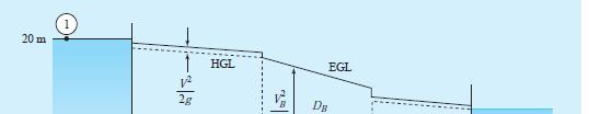
14 Hydraulic and Energy Grade Lines The hydraulic grade line (HGL), the dashed d line in Fig. 7.17, in apiping i system is formed by the locus of points located a distance p/γ above the center of the pipe, or p/γ +zaboveapreselecteddatum;theliquidina piezometer tube would rise to the HGL. The energy grade line (EGL), the solid line in Fig. 7.17, is formed by the locus of points a distance V 2 /2g above the HGL, or the distance V 2 /2g + p/γ + z above the datum; the liquid in a pitot tube would rise to the EGL. 14
15 The concepts of energy grade line and hydraulic grade line may also be applied to open channel flows. The HGL coincides with the free surface and the EGL is a distance V 2 /2gabovethefreesurface. The following points are noted relating to the HGL and the EGL: As the velocity goes to zero, the HGL and the EGL approach each other. Thus, in a reservoir, they are identical and lie on the surface (see Fig. 7.17). The EGL and, consequently, the HGL slope downward in the direction of the flow due to the head loss in the pipe. The greater the loss per unit length, the greater the slope. As the average velocity in the pipe increases, the loss per unit length increases. A sudden change occurs in the HGL and the EGL whenever a loss occurs due to a sudden geometry change, as represented by the valve or the sudden enlargement of Fig A jump occurs in the HGL and the EGL whenever useful energy is added to the fluid, as occurs with a pump, and a drop occurs if useful energy is extracted from the flow, as occurs with a turbine. 15
16 At points where the HGL passes through the centerline of the pipe, the pressure is zero. If the pipe lies above the HGL, there is a vacuum in the pipe, a condition that is often avoided, if possible, in the design of piping i systems; an exception would be in the design of a siphon. 16


17 17
18 18
19 19
20 Simple Pipe System with a Pump The head produced by a centrifugal pump and its efficiency η P (see Eq ) dependdon the discharge, as shown by the pump characteristic i curves, the solid curves in Fig Companies furnish such characteristic curves for each centrifugal pump manufactured. Such a curve provides one equation relating the flow rate Q and pump head H P. 20
21 The system demand curve is provided by the energy equation, which can typically be written as This is the system demand curve along ao with the characteristic aa ei i curve must be solved simultaneously to yield the desired flow rate. To determine the power requirement of the pump, p the efficiency η P must be used. Note that for the piping system, the required pump energy head H P, demanded by the energy equation, increases with Q and from the pump characteristic i curve we see that H P decreases with ih Q; hence the two curves will intersect at a point, called the operating point of the system. 21
22 22
23 23


24 24

25 25
26 26
27 27
28 Example: The flow rate is measured to be m 3 /s in the pipe shown. Find the loss coefficient of the valve if H = 4 cm. Ans: Example: Estimate t the flow rate to be expected throughh the plastic siphon shown if the diameter is 8 cm. Ans: m 3 /s 28
Hydraulic (Piezometric) Grade Lines (HGL) and
 Grade Lines (HGL) and") Hydraulic (Piezometric) Grade Lines (HGL) and Energy Grade Lines (EGL) When the energy equation is written between two points it is expresses as in the form of: Each term has a name and all terms have
Hydraulic (Piezometric) Grade Lines (HGL) and Energy Grade Lines (EGL) When the energy equation is written between two points it is expresses as in the form of: Each term has a name and all terms have
Hydraulics and hydrology
 Hydraulics and hydrology - project exercises - Class 4 and 5 Pipe flow Discharge (Q) (called also as the volume flow rate) is the volume of fluid that passes through an area per unit time. The discharge
FE Fluids Review March 23, 2012 Steve Burian (Civil & Environmental Engineering)
") Topic: Fluid Properties 1. If 6 m 3 of oil weighs 47 kn, calculate its specific weight, density, and specific gravity. 2. 10.0 L of an incompressible liquid exert a force of 20 N at the earth s surface.
Topic: Fluid Properties 1. If 6 m 3 of oil weighs 47 kn, calculate its specific weight, density, and specific gravity. 2. 10.0 L of an incompressible liquid exert a force of 20 N at the earth s surface.
Chapter (6) Energy Equation and Its Applications
 Energy Equation and Its Applications") Chapter (6) Energy Equation and Its Applications Bernoulli Equation Bernoulli equation is one of the most useful equations in fluid mechanics and hydraulics. And it s a statement of the principle of conservation
Chapter (6) Energy Equation and Its Applications Bernoulli Equation Bernoulli equation is one of the most useful equations in fluid mechanics and hydraulics. And it s a statement of the principle of conservation
Review of pipe flow: Friction & Minor Losses
 ENVE 204 Lecture -1 Review of pipe flow: Friction & Minor Losses Assist. Prof. Neslihan SEMERCİ Marmara University Department of Environmental Engineering Important Definitions Pressure Pipe Flow: Refers
Pressure Head: Pressure head is the height of a column of water that would exert a unit pressure equal to the pressure of the water.
 Design Manual Chapter - Stormwater D - Storm Sewer Design D- Storm Sewer Sizing A. Introduction The purpose of this section is to outline the basic hydraulic principles in order to determine the storm
1-Reynold s Experiment
 Lect.No.8 2 nd Semester Flow Dynamics in Closed Conduit (Pipe Flow) 1 of 21 The flow in closed conduit ( flow in pipe ) is differ from this occur in open channel where the flow in pipe is at a pressure
Chapter 7 The Energy Equation
 Chapter 7 The Energy Equation 7.1 Energy, Work, and Power When matter has energy, the matter can be used to do work. A fluid can have several forms of energy. For example a fluid jet has kinetic energy,
Chapter 8: Flow in Pipes
 Objectives 1. Have a deeper understanding of laminar and turbulent flow in pipes and the analysis of fully developed flow 2. Calculate the major and minor losses associated with pipe flow in piping networks
FACULTY OF CHEMICAL & ENERGY ENGINEERING FLUID MECHANICS LABORATORY TITLE OF EXPERIMENT: MINOR LOSSES IN PIPE (E4)
") FACULTY OF CHEMICAL & ENERGY ENGINEERING FLUID MECHANICS LABORATORY TITLE OF EXPERIMENT: MINOR LOSSES IN PIPE (E4) 1 1.0 Objectives The objective of this experiment is to calculate loss coefficient (K
FACULTY OF CHEMICAL & ENERGY ENGINEERING FLUID MECHANICS LABORATORY TITLE OF EXPERIMENT: MINOR LOSSES IN PIPE (E4) 1 1.0 Objectives The objective of this experiment is to calculate loss coefficient (K
Hydraulics. B.E. (Civil), Year/Part: II/II. Tutorial solutions: Pipe flow. Tutorial 1
, Year/Part: II/II. Tutorial solutions: Pipe flow. Tutorial 1") Hydraulics B.E. (Civil), Year/Part: II/II Tutorial solutions: Pipe flow Tutorial 1 -by Dr. K.N. Dulal Laminar flow 1. A pipe 200mm in diameter and 20km long conveys oil of density 900 kg/m 3 and viscosity
Hydraulics B.E. (Civil), Year/Part: II/II Tutorial solutions: Pipe flow Tutorial 1 -by Dr. K.N. Dulal Laminar flow 1. A pipe 200mm in diameter and 20km long conveys oil of density 900 kg/m 3 and viscosity
COURSE NUMBER: ME 321 Fluid Mechanics I 3 credit hour. Basic Equations in fluid Dynamics
 COURSE NUMBER: ME 321 Fluid Mechanics I 3 credit hour Basic Equations in fluid Dynamics Course teacher Dr. M. Mahbubur Razzaque Professor Department of Mechanical Engineering BUET 1 Description of Fluid
ME 309 Fluid Mechanics Fall 2010 Exam 2 1A. 1B.
 Fall 010 Exam 1A. 1B. Fall 010 Exam 1C. Water is flowing through a 180º bend. The inner and outer radii of the bend are 0.75 and 1.5 m, respectively. The velocity profile is approximated as C/r where C
Chapter 8: Flow in Pipes
 8-1 Introduction 8-2 Laminar and Turbulent Flows 8-3 The Entrance Region 8-4 Laminar Flow in Pipes 8-5 Turbulent Flow in Pipes 8-6 Fully Developed Pipe Flow 8-7 Minor Losses 8-8 Piping Networks and Pump
Viscous Flow in Ducts
 Dr. M. Siavashi Iran University of Science and Technology Spring 2014 Objectives 1. Have a deeper understanding of laminar and turbulent flow in pipes and the analysis of fully developed flow 2. Calculate
Pipe Flow. Lecture 17
 Pipe Flow Lecture 7 Pipe Flow and the Energy Equation For pipe flow, the Bernoulli equation alone is not sufficient. Friction loss along the pipe, and momentum loss through diameter changes and corners
Applied Fluid Mechanics
 Applied Fluid Mechanics 1. The Nature of Fluid and the Study of Fluid Mechanics 2. Viscosity of Fluid 3. Pressure Measurement 4. Forces Due to Static Fluid 5. Buoyancy and Stability 6. Flow of Fluid and
FLUID MECHANICS. Dynamics of Viscous Fluid Flow in Closed Pipe: Darcy-Weisbach equation for flow in pipes. Major and minor losses in pipe lines.
 FLUID MECHANICS Dynamics of iscous Fluid Flow in Closed Pipe: Darcy-Weisbach equation for flow in pipes. Major and minor losses in pipe lines. Dr. Mohsin Siddique Assistant Professor Steady Flow Through
STEADY FLOW THROUGH PIPES DARCY WEISBACH EQUATION FOR FLOW IN PIPES. HAZEN WILLIAM S FORMULA, LOSSES IN PIPELINES, HYDRAULIC GRADE LINES AND ENERGY
 STEADY FLOW THROUGH PIPES DARCY WEISBACH EQUATION FOR FLOW IN PIPES. HAZEN WILLIAM S FORMULA, LOSSES IN PIPELINES, HYDRAULIC GRADE LINES AND ENERGY LINES 1 SIGNIFICANCE OF CONDUITS In considering the convenience
Chapter (3) Water Flow in Pipes
 Water Flow in Pipes") Chapter (3) Water Flow in Pipes Water Flow in Pipes Bernoulli Equation Recall fluid mechanics course, the Bernoulli equation is: P 1 ρg + v 1 g + z 1 = P ρg + v g + z h P + h T + h L Here, we want to study
Chapter (3) Water Flow in Pipes Water Flow in Pipes Bernoulli Equation Recall fluid mechanics course, the Bernoulli equation is: P 1 ρg + v 1 g + z 1 = P ρg + v g + z h P + h T + h L Here, we want to study
INSTRUCTIONS FOR LABORATORY EXPERIMENT IN FLUID MECHANICS
 INSTRUCTIONS FOR LABORATORY EXPERIMENT IN FLUID MECHANICS VT2010 Pipe Flow: General Information: Attendance at the laboratory experiment is required for completion of the course. The experiments will be
vector H. If O is the point about which moments are desired, the angular moment about O is given:
 The angular momentum A control volume analysis can be applied to the angular momentum, by letting B equal to angularmomentum vector H. If O is the point about which moments are desired, the angular moment
LOSSES DUE TO PIPE FITTINGS
 LOSSES DUE TO PIPE FITTINGS Aim: To determine the losses across the fittings in a pipe network Theory: The resistance to flow in a pipe network causes loss in the pressure head along the flow. The overall
Objectives. Conservation of mass principle: Mass Equation The Bernoulli equation Conservation of energy principle: Energy equation
 Objectives Conservation of mass principle: Mass Equation The Bernoulli equation Conservation of energy principle: Energy equation Conservation of Mass Conservation of Mass Mass, like energy, is a conserved
Water Circuit Lab. The pressure drop along a straight pipe segment can be calculated using the following set of equations:
 Water Circuit Lab When a fluid flows in a conduit, there is friction between the flowing fluid and the pipe walls. The result of this friction is a net loss of energy in the flowing fluid. The fluid pressure
Lesson 6 Review of fundamentals: Fluid flow
 Lesson 6 Review of fundamentals: Fluid flow The specific objective of this lesson is to conduct a brief review of the fundamentals of fluid flow and present: A general equation for conservation of mass
Chapter 3 Bernoulli Equation
 1 Bernoulli Equation 3.1 Flow Patterns: Streamlines, Pathlines, Streaklines 1) A streamline, is a line that is everywhere tangent to the velocity vector at a given instant. Examples of streamlines around
Experiment (4): Flow measurement
: Flow measurement") Experiment (4): Flow measurement Introduction: The flow measuring apparatus is used to familiarize the students with typical methods of flow measurement of an incompressible fluid and, at the same time
Experiment (4): Flow measurement Introduction: The flow measuring apparatus is used to familiarize the students with typical methods of flow measurement of an incompressible fluid and, at the same time
Chapter 6. Losses due to Fluid Friction
 Chapter 6 Losses due to Fluid Friction 1 Objectives ä To measure the pressure drop in the straight section of smooth, rough, and packed pipes as a function of flow rate. ä To correlate this in terms of
FLUID MECHANICS D203 SAE SOLUTIONS TUTORIAL 2 APPLICATIONS OF BERNOULLI SELF ASSESSMENT EXERCISE 1
 FLUID MECHANICS D203 SAE SOLUTIONS TUTORIAL 2 APPLICATIONS OF BERNOULLI SELF ASSESSMENT EXERCISE 1 1. A pipe 100 mm bore diameter carries oil of density 900 kg/m3 at a rate of 4 kg/s. The pipe reduces
Chapter 10 Flow in Conduits
 Chapter 10 Flow in Conduits 10.1 Classifying Flow Laminar Flow and Turbulent Flow Laminar flow Unpredictable Turbulent flow Near entrance: undeveloped developing flow In developing flow, the wall shear
HEADLOSS ESTIMATION. Mekanika Fluida 1 HST
 HEADLOSS ESTIMATION Mekanika Fluida HST Friction Factor : Major losses Laminar low Hagen-Poiseuille Turbulent (Smoot, Transition, Roug) Colebrook Formula Moody diagram Swamee-Jain 3 Laminar Flow Friction
Chapter 3 Water Flow in Pipes
 The Islamic University o Gaza Faculty o Engineering Civil Engineering Department Hydraulics - ECI 33 Chapter 3 Water Flow in Pipes 3. Description o A Pipe Flow Water pipes in our homes and the distribution
ENGINEERING FLUID MECHANICS. CHAPTER 1 Properties of Fluids
 CHAPTER 1 Properties of Fluids ENGINEERING FLUID MECHANICS 1.1 Introduction 1.2 Development of Fluid Mechanics 1.3 Units of Measurement (SI units) 1.4 Mass, Density, Specific Weight, Specific Volume, Specific
EXPERIMENT NO: F5. Losses in Piping Systems
 SJSU ME115 - THERMAL ENGINEERING LAB EXPERIMENT NO: F5 Losses in Piping Systems Objective One of the most common problems in fluid mechanics is the estimation of pressure loss. It is the objective of this
EXPERIMENT No.1 FLOW MEASUREMENT BY ORIFICEMETER
 EXPERIMENT No.1 FLOW MEASUREMENT BY ORIFICEMETER 1.1 AIM: To determine the co-efficient of discharge of the orifice meter 1.2 EQUIPMENTS REQUIRED: Orifice meter test rig, Stopwatch 1.3 PREPARATION 1.3.1
NPTEL Quiz Hydraulics
 Introduction NPTEL Quiz Hydraulics 1. An ideal fluid is a. One which obeys Newton s law of viscosity b. Frictionless and incompressible c. Very viscous d. Frictionless and compressible 2. The unit of kinematic
Friction Factors and Drag Coefficients
 Levicky 1 Friction Factors and Drag Coefficients Several equations that we have seen have included terms to represent dissipation of energy due to the viscous nature of fluid flow. For example, in the
CEE 3310 Control Volume Analysis, Oct. 7, D Steady State Head Form of the Energy Equation P. P 2g + z h f + h p h s.
 CEE 3310 Control Volume Analysis, Oct. 7, 2015 81 3.21 Review 1-D Steady State Head Form of the Energy Equation ( ) ( ) 2g + z = 2g + z h f + h p h s out where h f is the friction head loss (which combines
Rate of Flow Quantity of fluid passing through any section (area) per unit time
 per unit time") Kinematics of Fluid Flow Kinematics is the science which deals with study of motion of liquids without considering the forces causing the motion. Rate of Flow Quantity of fluid passing through any section
Kinematics of Fluid Flow Kinematics is the science which deals with study of motion of liquids without considering the forces causing the motion. Rate of Flow Quantity of fluid passing through any section
Chapter Four fluid flow mass, energy, Bernoulli and momentum
 4-1Conservation of Mass Principle Consider a control volume of arbitrary shape, as shown in Fig (4-1). Figure (4-1): the differential control volume and differential control volume (Total mass entering
9. Pumps (compressors & turbines) Partly based on Chapter 10 of the De Nevers textbook.
 Partly based on Chapter 10 of the De Nevers textbook.") Lecture Notes CHE 31 Fluid Mechanics (Fall 010) 9. Pumps (compressors & turbines) Partly based on Chapter 10 of the De Nevers textbook. Basics (pressure head, efficiency, working point, stability) Pumps
Lecture Notes CHE 31 Fluid Mechanics (Fall 010) 9. Pumps (compressors & turbines) Partly based on Chapter 10 of the De Nevers textbook. Basics (pressure head, efficiency, working point, stability) Pumps
Piping Systems and Flow Analysis (Chapter 3)
") Piping Systems and Flow Analysis (Chapter 3) 2 Learning Outcomes (Chapter 3) Losses in Piping Systems Major losses Minor losses Pipe Networks Pipes in series Pipes in parallel Manifolds and Distribution
Piping Systems and Flow Analysis (Chapter 3) 2 Learning Outcomes (Chapter 3) Losses in Piping Systems Major losses Minor losses Pipe Networks Pipes in series Pipes in parallel Manifolds and Distribution
CIVE HYDRAULIC ENGINEERING PART II Pierre Julien Colorado State University
 1 CIVE 401 - HYDRAULIC ENGINEERING PART II Pierre Julien Colorado State University Problems with and are considered moderate and those with are the longest and most difficult. In 2018 solve the problems
Experiment- To determine the coefficient of impact for vanes. Experiment To determine the coefficient of discharge of an orifice meter.
 SUBJECT: FLUID MECHANICS VIVA QUESTIONS (M.E 4 th SEM) Experiment- To determine the coefficient of impact for vanes. Q1. Explain impulse momentum principal. Ans1. Momentum equation is based on Newton s
An overview of the Hydraulics of Water Distribution Networks
 An overview of the Hydraulics of Water Distribution Networks June 21, 2017 by, P.E. Senior Water Resources Specialist, Santa Clara Valley Water District Adjunct Faculty, San José State University 1 Outline
Hydraulics for Urban Storm Drainage
 Urban Hydraulics Hydraulics for Urban Storm Drainage Learning objectives: understanding of basic concepts of fluid flow and how to analyze conduit flows, free surface flows. to analyze, hydrostatic pressure
PROPERTIES OF FLUIDS
 Unit - I Chapter - PROPERTIES OF FLUIDS Solutions of Examples for Practice Example.9 : Given data : u = y y, = 8 Poise = 0.8 Pa-s To find : Shear stress. Step - : Calculate the shear stress at various
3.25 Pressure form of Bernoulli Equation
 CEE 3310 Control Volume Analysis, Oct 3, 2012 83 3.24 Review The Energy Equation Q Ẇshaft = d dt CV ) (û + v2 2 + gz ρ d + (û + v2 CS 2 + gz + ) ρ( v n) da ρ where Q is the heat energy transfer rate, Ẇ
Atmospheric pressure. 9 ft. 6 ft
 Name CEE 4 Final Exam, Aut 00; Answer all questions; 145 points total. Some information that might be helpful is provided below. A Moody diagram is printed on the last page. For water at 0 o C (68 o F):
If a stream of uniform velocity flows into a blunt body, the stream lines take a pattern similar to this: Streamlines around a blunt body
 Venturimeter & Orificemeter ELEMENTARY HYDRAULICS National Certificate in Technology (Civil Engineering) Chapter 5 Applications of the Bernoulli Equation The Bernoulli equation can be applied to a great
FE Exam Fluids Review October 23, Important Concepts
 FE Exam Fluids Review October 3, 013 mportant Concepts Density, specific volume, specific weight, specific gravity (Water 1000 kg/m^3, Air 1. kg/m^3) Meaning & Symbols? Stress, Pressure, Viscosity; Meaning
Fluids Engineering. Pipeline Systems 2. Course teacher Dr. M. Mahbubur Razzaque Professor Department of Mechanical Engineering BUET
 COURSE NUMBER: ME 423 Fluids Engineering Pipeline Systems 2 Course teacher Dr. M. Mahbubur Razzaque Professor Department of Mechanical Engineering BUET 1 SERIES PIPE FLOW WITH PUMP(S) 2 3 4 Colebrook-
Chapter Four Hydraulic Machines
 Contents 1- Introduction. - Pumps. Chapter Four Hydraulic Machines (لفرع الميكانيك العام فقط ( Turbines. -3 4- Cavitation in hydraulic machines. 5- Examples. 6- Problems; sheet No. 4 (Pumps) 7- Problems;
2.The lines that are tangent to the velocity vectors throughout the flow field are called steady flow lines. True or False A. True B.
 CHAPTER 03 1. Write Newton's second law of motion. YOUR ANSWER: F = ma 2.The lines that are tangent to the velocity vectors throughout the flow field are called steady flow lines. True or False 3.Streamwise
FLOW IN CONDUITS. Shear stress distribution across a pipe section. Chapter 10
 Chapter 10 Shear stress distribution across a pipe section FLOW IN CONDUITS For steady, uniform flow, the momentum balance in s for the fluid cylinder yields Fluid Mechanics, Spring Term 2010 Velocity
For example an empty bucket weighs 2.0kg. After 7 seconds of collecting water the bucket weighs 8.0kg, then:
 Hydraulic Coefficient & Flow Measurements ELEMENTARY HYDRAULICS National Certificate in Technology (Civil Engineering) Chapter 3 1. Mass flow rate If we want to measure the rate at which water is flowing
Fluid Mechanics c) Orificemeter a) Viscous force, Turbulence force, Compressible force a) Turbulence force c) Integration d) The flow is rotational
 Orificemeter a) Viscous force, Turbulence force, Compressible force a) Turbulence force c) Integration d) The flow is rotational") Fluid Mechanics 1. Which is the cheapest device for measuring flow / discharge rate. a) Venturimeter b) Pitot tube c) Orificemeter d) None of the mentioned 2. Which forces are neglected to obtain Euler
Fluid Mechanics 1. Which is the cheapest device for measuring flow / discharge rate. a) Venturimeter b) Pitot tube c) Orificemeter d) None of the mentioned 2. Which forces are neglected to obtain Euler
Chapter 4 DYNAMICS OF FLUID FLOW
 Faculty Of Engineering at Shobra nd Year Civil - 016 Chapter 4 DYNAMICS OF FLUID FLOW 4-1 Types of Energy 4- Euler s Equation 4-3 Bernoulli s Equation 4-4 Total Energy Line (TEL) and Hydraulic Grade Line
ME 305 Fluid Mechanics I. Part 8 Viscous Flow in Pipes and Ducts. Flow in Pipes and Ducts. Flow in Pipes and Ducts (cont d)
") ME 305 Fluid Mechanics I Flow in Pipes and Ducts Flow in closed conduits (circular pipes and non-circular ducts) are very common. Part 8 Viscous Flow in Pipes and Ducts These presentations are prepared
ME 305 Fluid Mechanics I Flow in Pipes and Ducts Flow in closed conduits (circular pipes and non-circular ducts) are very common. Part 8 Viscous Flow in Pipes and Ducts These presentations are prepared
Mechanical Engineering Programme of Study
 Mechanical Engineering Programme of Study Fluid Mechanics Instructor: Marios M. Fyrillas Email: eng.fm@fit.ac.cy SOLVED EXAMPLES ON VISCOUS FLOW 1. Consider steady, laminar flow between two fixed parallel
CEE 3310 Control Volume Analysis, Oct. 10, = dt. sys
 CEE 3310 Control Volume Analysis, Oct. 10, 2018 77 3.16 Review First Law of Thermodynamics ( ) de = dt Q Ẇ sys Sign convention: Work done by the surroundings on the system < 0, example, a pump! Work done
Lesson 37 Transmission Of Air In Air Conditioning Ducts
 Lesson 37 Transmission Of Air In Air Conditioning Ducts Version 1 ME, IIT Kharagpur 1 The specific objectives of this chapter are to: 1. Describe an Air Handling Unit (AHU) and its functions (Section 37.1).
A Model Answer for. Problem Set #7
 A Model Answer for Problem Set #7 Pipe Flow and Applications Problem.1 A pipeline 70 m long connects two reservoirs having a difference in water level of 6.0 m. The pipe rises to a height of 3.0 m above
FLOW FRICTION CHARACTERISTICS OF CONCRETE PRESSURE PIPE
 11 ACPPA TECHNICAL SERIES FLOW FRICTION CHARACTERISTICS OF CONCRETE PRESSURE PIPE This paper presents formulas to assist in hydraulic design of concrete pressure pipe. There are many formulas to calculate
FLUID MECHANICS PROF. DR. METİN GÜNER COMPILER
 FLUID MECHANICS PROF. DR. METİN GÜNER COMPILER ANKARA UNIVERSITY FACULTY OF AGRICULTURE DEPARTMENT OF AGRICULTURAL MACHINERY AND TECHNOLOGIES ENGINEERING 1 5. FLOW IN PIPES Liquid or gas flow through pipes
s and FE X. A. Flow measurement B. properties C. statics D. impulse, and momentum equations E. Pipe and other internal flow 7% of FE Morning Session I
 Fundamentals of Engineering (FE) Exam General Section Steven Burian Civil & Environmental Engineering October 26, 2010 s and FE X. A. Flow measurement B. properties C. statics D. impulse, and momentum
2 Internal Fluid Flow
 Internal Fluid Flow.1 Definitions Fluid Dynamics The study of fluids in motion. Static Pressure The pressure at a given point exerted by the static head of the fluid present directly above that point.
Mass of fluid leaving per unit time
 5 ENERGY EQUATION OF FLUID MOTION 5.1 Eulerian Approach & Control Volume In order to develop the equations that describe a flow, it is assumed that fluids are subject to certain fundamental laws of physics.
EXPERIMENT II - FRICTION LOSS ALONG PIPE AND LOSSES AT PIPE FITTINGS
 MM 30 FLUID MECHANICS II Prof. Dr. Nuri YÜCEL Yrd. Doç. Dr. Nureddin DİNLER Arş. Gör. Dr. Salih KARAASLAN Arş. Gör. Fatih AKTAŞ EXPERIMENT II - FRICTION LOSS ALONG PIPE AND LOSSES AT PIPE FITTINGS A. Objective:
LECTURE 6- ENERGY LOSSES IN HYDRAULIC SYSTEMS SELF EVALUATION QUESTIONS AND ANSWERS
 LECTURE 6- ENERGY LOSSES IN HYDRAULIC SYSTEMS SELF EVALUATION QUESTIONS AND ANSWERS 1. What is the head loss ( in units of bars) across a 30mm wide open gate valve when oil ( SG=0.9) flow through at a
Chapter 10: Flow Flow in in Conduits Conduits Dr Ali Jawarneh
 Chater 10: Flow in Conduits By Dr Ali Jawarneh Hashemite University 1 Outline In this chater we will: Analyse the shear stress distribution across a ie section. Discuss and analyse the case of laminar
Reynolds, an engineering professor in early 1880 demonstrated two different types of flow through an experiment:
 7 STEADY FLOW IN PIPES 7.1 Reynolds Number Reynolds, an engineering professor in early 1880 demonstrated two different types of flow through an experiment: Laminar flow Turbulent flow Reynolds apparatus
PIPING SYSTEMS. Pipe and Tubing Standards Sizes for pipes and tubes are standardized. Pipes are specified by a nominal diameter and a schedule number.
 PIPING SYSTEMS In this chapter we will review some of the basic concepts associated with piping systems. Topics that will be considered in this chapter are - Pipe and tubing standards - Effective and hydraulic
Chapter Four Hydraulic Machines
 Contents 1- Introduction. 2- Pumps. Chapter Four Hydraulic Machines (لفرع الميكانيك العام فقط ( Turbines. -3 4- Cavitation in hydraulic machines. 5- Examples. 6- Problems; sheet No. 4 (Pumps) 7- Problems;
Basics of fluid flow. Types of flow. Fluid Ideal/Real Compressible/Incompressible
 Basics of fluid flow Types of flow Fluid Ideal/Real Compressible/Incompressible Flow Steady/Unsteady Uniform/Non-uniform Laminar/Turbulent Pressure/Gravity (free surface) 1 Basics of fluid flow (Chapter
EGN 3353C Fluid Mechanics
 Lecture 8 Bernoulli s Equation: Limitations and Applications Last time, we derived the steady form of Bernoulli s Equation along a streamline p + ρv + ρgz = P t static hydrostatic total pressure q = dynamic
INSTITUTE OF AERONAUTICAL ENGINEERING Dundigal, Hyderabad AERONAUTICAL ENGINEERING QUESTION BANK : AERONAUTICAL ENGINEERING.
 Course Name Course Code Class Branch INSTITUTE OF AERONAUTICAL ENGINEERING Dundigal, Hyderabad - 00 0 AERONAUTICAL ENGINEERING : Mechanics of Fluids : A00 : II-I- B. Tech Year : 0 0 Course Coordinator
Fundamentals of Fluid Mechanics
 Sixth Edition Fundamentals of Fluid Mechanics International Student Version BRUCE R. MUNSON DONALD F. YOUNG Department of Aerospace Engineering and Engineering Mechanics THEODORE H. OKIISHI Department
10.52 Mechanics of Fluids Spring 2006 Problem Set 3
 10.52 Mechanics of Fluids Spring 2006 Problem Set 3 Problem 1 Mass transfer studies involving the transport of a solute from a gas to a liquid often involve the use of a laminar jet of liquid. The situation
Lecture 3 The energy equation
 Lecture 3 The energy equation Dr Tim Gough: t.gough@bradford.ac.uk General information Lab groups now assigned Timetable up to week 6 published Is there anyone not yet on the list? Week 3 Week 4 Week 5
New Website: M P E il Add. Mr. Peterson s Address:
 Brad Peterson, P.E. New Website: http://njut009fall.weebly.com M P E il Add Mr. Peterson s Email Address: bradpeterson@engineer.com If 6 m 3 of oil weighs 47 kn calculate its If 6 m 3 of oil weighs 47
LEAKLESS COOLING SYSTEM V.2 PRESSURE DROP CALCULATIONS AND ASSUMPTIONS
 CH-1211 Geneva 23 Switzerland EDMS No. ST/CV - Cooling of Electronics & Detectors GUIDE LEAKLESS COOLING SYSTEM V.2 PRESSURE DROP CALCULATIONS AND ASSUMPTIONS Objectives Guide to Leakless Cooling System
CVE 372 HYDROMECHANICS EXERCISE PROBLEMS
 VE 37 HYDROMEHNIS EXERISE PROLEMS 1. pump that has the characteristic curve shown in the accompanying graph is to be installed in the system shown. What will be the discharge of water in the system? Take
UNIT I FLUID PROPERTIES AND STATICS
 SIDDHARTH GROUP OF INSTITUTIONS :: PUTTUR Siddharth Nagar, Narayanavanam Road 517583 QUESTION BANK (DESCRIPTIVE) Subject with Code : Fluid Mechanics (16CE106) Year & Sem: II-B.Tech & I-Sem Course & Branch:
M E 320 Professor John M. Cimbala Lecture 24
 M E 30 Professor John M. Cimbala Lecture 4 Today, we will: Discuss pump performance curves Discuss how to match a pump and a piping system, and do some example problems. Pump Performance a. Pump performance
1.060 Engineering Mechanics II Spring Problem Set 4
 1.060 Engineering Mechanics II Spring 2006 Due on Monday, March 20th Problem Set 4 Important note: Please start a new sheet of paper for each problem in the problem set. Write the names of the group members
V/ t = 0 p/ t = 0 ρ/ t = 0. V/ s = 0 p/ s = 0 ρ/ s = 0
 UNIT III FLOW THROUGH PIPES 1. List the types of fluid flow. Steady and unsteady flow Uniform and non-uniform flow Laminar and Turbulent flow Compressible and incompressible flow Rotational and ir-rotational
Properties and Definitions Useful constants, properties, and conversions
 Properties and Definitions Useful constants, properties, and conversions gc = 32.2 ft/sec 2 [lbm-ft/lbf-sec 2 ] ρwater = 1.96 slugs/ft 3 γwater = 62.4 lb/ft 3 1 ft 3 /sec = 449 gpm 1 mgd = 1.547 ft 3 /sec
Dr. Muhammad Ali Shamim ; Internal 652
 Dr. Muhammad Ali Shamim ali.shamim@uettaxila.edu.pk 051-904765; Internal 65 Channel Tranistions A channel transition is defined as change in channel cross section e.g. change in channel width and/or channel
CHAPTER EIGHT P U M P I N G O F L I Q U I D S
 CHAPTER EIGHT P U M P I N G O F L I Q U I D S Pupmps are devices for supplying energy or head to a flowing liquid in order to overcome head losses due to friction and also if necessary, to raise liquid
5 ENERGY EQUATION OF FLUID MOTION
 5 ENERGY EQUATION OF FLUID MOTION 5.1 Introduction In order to develop the equations that describe a flow, it is assumed that fluids are subject to certain fundamental laws of physics. The pertinent laws
Chapter 5: Mass, Bernoulli, and Energy Equations
 Chapter 5: Mass, Bernoulli, and Energy Equations Introduction This chapter deals with 3 equations commonly used in fluid mechanics The mass equation is an expression of the conservation of mass principle.
ME 305 Fluid Mechanics I. Chapter 8 Viscous Flow in Pipes and Ducts
 ME 305 Fluid Mechanics I Chapter 8 Viscous Flow in Pipes and Ducts These presentations are prepared by Dr. Cüneyt Sert Department of Mechanical Engineering Middle East Technical University Ankara, Turkey
Experiment 7 Energy Loss in a Hydraulic Jump
 Experiment 7 Energ Loss in a Hdraulic Jump n Purpose: The purpose of this experiment is to examine the transition from supercritical (rapid) flow to subcritical (slow) flow in an open channel and to analze
DEPARTMENT OF CIVIL AND ENVIRONMENTAL ENGINEERING Urban Drainage: Hydraulics. Solutions to problem sheet 2: Flows in open channels
 DEPRTMENT OF CIVIL ND ENVIRONMENTL ENGINEERING Urban Drainage: Hydraulics Solutions to problem sheet 2: Flows in open channels 1. rectangular channel of 1 m width carries water at a rate 0.1 m 3 /s. Plot
CHAPTER THREE FLUID MECHANICS
 CHAPTER THREE FLUID MECHANICS 3.1. Measurement of Pressure Drop for Flow through Different Geometries 3.. Determination of Operating Characteristics of a Centrifugal Pump 3.3. Energy Losses in Pipes under
Applied Fluid Mechanics
 Applied Fluid Mechanics 1. The Nature of Fluid and the Study of Fluid Mechanics 2. Viscosity of Fluid 3. Pressure Measurement 4. Forces Due to Static Fluid 5. Buoyancy and Stability 6. Flow of Fluid and
When water (fluid) flows in a pipe, for example from point A to point B, pressure drop will occur due to the energy losses (major and minor losses).
 flows in a pipe, for example from point A to point B, pressure drop will occur due to the energy losses (major and minor losses).") PRESSURE DROP AND OSSES IN PIPE When water (luid) lows in a pipe, or example rom point A to point B, pressure drop will occur due to the energy losses (major and minor losses). A B Bernoulli equation:
PRESSURE DROP AND OSSES IN PIPE When water (luid) lows in a pipe, or example rom point A to point B, pressure drop will occur due to the energy losses (major and minor losses). A B Bernoulli equation: