Fluid Statics, Hydrodynamics and Hydraulic Machines
|
|
|
- Erik McDowell
- 5 years ago
- Views:
Transcription

1 Fluid Statics, Hydrodynamics and Hydraulic Machines Bobby Rauf 1
 Gaseous fluids are compressible 4) Fluid pressure, defined as force per unit area, is measured in pounds per square inch, psi, or pounds per square foot, psf, in US unit system.")
2 Fluid Facts 1) Liquids and gases can both be categorized as fluids. 2) Liquid fluids are assumed be incompressible. 3) Gaseous fluids are compressible 4) Fluid pressure, defined as force per unit area, is measured in pounds per square inch, psi, or pounds per square foot, psf, in US unit system. Pressure is measured in Pascals, Pa, or kilopascals, kpa, in the SI (metric) System. 5) Standard Atmospheric Pressure: 1.00 Atm; 14.7 psia; inches of water gage; in Hg; 760 mm Hg; x 10 5 Pa; kpa. 6) P abs = P gage + P atm 2
3 Fluid Facts 7) Fluid Density = = mass / volume = 1 / Specific Volume 8) Fluid Density,, in US units: lbm / ft 3 9) Fluid Density,, in SI units: Kg / m 3 10) Specific Gravity of Liquid = SG liquid = liquid / water 11) Specific Gravity of Gas = SG gas = gas / air 12) Specific Weight of Fluid = = g. ; in lbf / ft 3 or N / m 3 13) STP, Standard Temperature Pressure: 0 C ( 32 F); kpa, or 1 atm, or 1 bar (14.7 psi). 14) r h = Hydraulic Radius = Area in Flow / Wetted Perimeter 3

4 FLUID STATICS - Manometer p 1 +.g.h = p 2 p 1 p2 h If p 1 represents atm. pressure, then: p 2 - p 1 = p gage, 2 =.g.h 4
5 Manometer & Multiple Fluid Densities p g. h g. h 2 = p p 0 p h 2 h 1 If p 0 represents atm. pressure, then: p - p 0 = p gage = 1.g. h g. h 2 5
6 Problem 1 Inverted Fluid A glass filled with a fluid is inverted. The bottom is open. See figure 1. What is the pressure at the closed end A? The pressure, P A, at point A, plus the pressure (.g.h) exerted by the water equals the atmospheric pressure, P atm, outside the glass. 6


7 Problem 1 Figure 1 PA +.g.h = P atm PA = P atm -.g.h P A A.g.h = Wt. Of the Water h D P atm 7
8 HYDRODYNAMICS - Problem 2 Consider the holding tank shown in figure 2. Calculate the velocity of the water exiting to the atmosphere. 8
9 Problem 2; Figure 2 v 2m P 1 = P atm 1 P 2 = P atm 2 9
10 Problem 2, contd. Apply Bernoulli s equation between the free surface (point 1) and the exit (point 2) g.z 1 + v 12 /2 + p 1 / = g.z 2 + v 22 /2 + p 2 / {SI} p 1 = p 2 (both are, or are at, atmospheric pressure) v 1 = 0 (the free surface is stationary) g.z 1 + (0) = g.z 2 + v 22 /2 + (p 2 / - p 1 / ) g.z 1 = g.z 2 + v 22 /2 10
11 Problem 2, contd. g.z 1 = g.z 2 + v 22 /2 v 2 = 2.g. (z 1 - z 2 ) = (2).(9.81).(2) = 6.3 m/s 11
12 Problem 3 A pressure tank contains a fluid with weight density 81.5 lbf/ft 3 ( ). The pressure in the air space is 100 psia. Fluid exits to the atmosphere from the bottom of the tank. What is the exit velocity, v? 12
13 Problem 3 p v 1, z 1, p 10 ft v v, z 2, p atm 13
14 Problem 3 Apply Bernoulli s equation, for energy conservation, between the surface and the exit at the lower right end: p/ + g.z 1 +v 12 /2 = p atm / + g.z 2 + v 2 /2 {SI} v 1 =0 (at the free surface), z 2 =0 (at the exit) p/ + g.z 1 = p atm / + v 2 /2 14
15 Problem 3, contd. p/ + g.z 1 = p atm / + v 2 /2 v = 2.g.{(p - p atm ) /.g+z 1 )} Since p.g = = 81.5 lbf/ft 3, v = (2).(32.2ft/sec 2 )[(100 psi- 14.7psi).(144in 2 /ft 2 )/ 81.5lbf/ft 3 +10ft] v = ft/sec 15
16 Problem 3 - i Buoyancy A hot air balloon is to used to transport a welder across a ravine. The balloon and the payload, including the welder and other accessories, have a mass of 200 kg. The ambient pressure and temperature are 102 kpa and 15.6 C. Assume wind to be calm, aloft and at ground elevation. (a) If density of ambient air is 1.2 kg/m 3 and if air in the balloon can be heated to a density of 1.0 kg/m 3, determine the volume and the radius of the balloon to achieve a lift off. (b) To what temperature must the air in the balloon be heated in order to achieve the density to 1.0 kg/m 3? 16


17 Problem 3 I Buoyancy
18 Problem 3 I, contd. Buoyancy Solution 3 i Hot Air = 1.0 kg/m 3 Amb. Air = 1.2 kg/m 3 P Amb = 102 kpa = 102,000 Pa Total Load, including the Payload & the Baloon = 200 Kg V HA = Volume of Hot Air in the Baloon = V AA = Volume of Ambient Air Displaced W payload + W balloon = 200 kg x g W hot air in balloon W amb. air displaced = 1.0 x g x V HA = 1.0 x g x V AA = 1.2 x g x V AA = 1.2 x g x V HA 18
19 Problem 3 I, contd. Buoyancy Solution 3 i (W payload + W balloon ) + W hot air in balloon = W amb. air displaced (200 kg x g) x g x V HA = 1.2 x g x V HA 200 kg kg/m 3 x V HA = 1.2 kg/m 3 x V HA V HA = V AA = 1000 m 3 Volume of a Spherical Baloon = V = 4/3 x 3.14 x r b 3 Radius of the Baloon = r b = {(V x 3/4) x (1/3.14)} 1/3 = m 19
20 Problem 3 I, contd. Buoyancy Solution 3 i b) Calculate the temperature of the hot air in the balloon for a density of 1.0 kg / m 3 = T HA For ideal gases, p = x R x T HA T HA = p / ( R x ) = K Or, T HA = 82.8 C Note: Max. Op. Temp for Nylon/Nymex Balloon: 120 C 20
21 Problem 3 I, contd. Buoyancy Solution 3 i Ancillary Note: Verification of the ambient air density assumption of 1.2 kg/m 3 For T Amb = 15.6 C = K Ambient Air = p / (R x T Amb ) = 102,000 / (286 x 288.6) = 1.2 kg/m 3 21
22 Problem 4 Calculate the overturning moment, per unit width, acting on the dam shown below: h = 8 ft & h av = ½(0 + 8) h av = 8/2 ft = 4 ft 1/3h h r = 2/3h F P av = P =. g. h av =. h av Heel Toe = Specific weight of water = 62.4 lbf/ft 3 22


23 Problem 4 Typical Hydroelectric Dam Construction : 23
24 Problem 4, contd. F = P av. A =. g. h av. A =. h av A F = (62.4 lbf/ft 3 ). (4). ( 8 x 1) F = lbf F per foot = lbf /ft M = Moment (per foot) = F per foot x 1/3h M = Moment (per foot) = lbf/ft x (8/3 ft) M = 5325 ft lbf/ft Ancillary questions: What force is needed to prevent the dam from sliding and what constitutes it? 24
25 Problem 4 - i Calculate the horizontal and vertical components of the resultant force on a 2 meter wide inclined surface in the reservoir shown below. Note that this reservoir has just experienced a massive oil spill. This oil has a density of 900 kg/m 3 Oil Slick h o = 0.3 m h 2 = 2 m 30 Water 30 h 1 = 1 m h i = 1 m 25
26 Problem 4 i, contd. Given: Density of Oil, o = 900 kg/m 3 Density of Water, w = 1000 kg/m 3 Angle of the Inclined Plane, = 30 Height of the Inclined Surface, h i = 1 m Depth of Water Above Inclined Surface, h 1 = 1 m Total Height or Depth of Water, h 2 = h 1 + h i = 2.0 m Depth of the Oil Slick, h o = 0.3 m Avg. Depth of Water Above Incl. Surface = h w = 1/2 x (h 2 + h 1 ) = 1.5 m 26
27 Problem 4 i, contd. Length of the Incl. Surface = h i /Sin(30) = 2.0 m Width of the Inclined Surface = 2 m (Given) Area of the Inclined Surface Section = 2m x 2m = 4.0 m 2 Pressure Contributed by the Layer of Oil = o x g x h o = 2,649 N/m 2 or Pa Average Pressure Contributed by the Water = = 14,715 N/m 2 or Pa w x g x h w Total Average Pressure in the Water at Inclined Surface: 17,364 N/m 2 or Pa 27
28 Problem 4 I, contd. Resultant Force Component Analysis: R R y R x 28
 = 60,150 N Rx, the x - Comp.")
29 Problem 4 i, contd. Perp. Resultant Force on any Point Along the Incl. Surface = Total Avg. Press x Area of Incl. Surface = 69,455 N Ry, the y - Comp. of the Resultant Force = R x Cos ( ) = 60,150 N Rx, the x - Comp. of the Resultant Force = R x Sin ( ) = 34,727 N 29


30 Problem 5 Figures 1 and 2, below, depict a pitot tube arrangement devised to measure the flow rate of water. Calculate the height of mercury column that would be sustained by the velocity pressure of the water. v = 10 m/s Water Mercury 30
31 Problem 5, contd. v 2 = v = 15 m/s 2 1 v 1 = 0 z 1 = z 2 and z 1 - z 2 = 0 z Hg = z water =? water = Density of water is 1000 kg / m 3 mercury = The density of mercury is 13,567 kg/m 3 31
32 Problem 5, contd. Apply Bernoulli s energy conservation equation at points 1 and 2, for fluid dynamics portion: p 1 / + g.z 1 +v 12 /2 = p 2 / + g.z 2 + v 22 /2 {SI} Since z 1 - z 2 = 0, v 1 = 0 and = water = 1000 kg/m 3 p 1 / = p 2 / + v 22 /2 p 1 - p 2 = (v 22 /2). =(225/2) = 112,500 pa 32
33 Problem 5, contd. Apply fluid statics principle to the pitot tube segment: p 2 + mercury. g. z Hg = p 1 + water. g. z water p 1 - p 2 = mercury. g. z Hg - water. g. z water z Hg = z water = (p 1 - p 2 ) / g / ( mercury - water ) z Hg = 112,500 / (9.81) / (13, ) = m 33
34 Problem 6 An irrigation water channel, or canal, is to be modified. The current and future specifications are listed below: Change Orig. Shape As % of Orig. New Shape Side Elevation or Vertical Component of the Side = 10 ft 10 ft Side Elevation Angle = Horizontal Component of the Side Wall = 0 ft ft Radians, Calct d. Length of Sides = ft ft, Calct d Length or Reach of the Water Channel, on Per Unit Basis: 1 30% 0.70 Fall or Drop on Per Unit Basis: Slope, "S" (Given) = Calct d Basin Width = 40 ft 20 ft Roughness, "n"


35 Problem 6, contd. Original or Existing Design: 40 ft 10 ft Proposed or Final Design: 10 ft 20 ft
36 Problem 6, contd. Determine the following water channel performance parameters based on the data provided above: a) The slope of the modified water channel is: Slope S = Rise / Run Let Rise = R, and let Run = Length = L and L o = Orig. L Therefore, S o = Original Slope = R o / L o = 0.05 {Given}, & R o = 0.05 L o Since the total Rise or Fall stays constant, R o = R f = R = 0.05 L o Also, the length of the modified channel = L f = (0.7) L o New Slope or Slope of the Modified Channel = R / L f = R / (0.7) L o = 0.05 L o / (0.7) L o =
37 Problem 6, contd. b) The volumetric flow rate in the original, or existing, design is : Manning s Equation : Volumetric Flow Rate = Q = (1.486/n).(A).(R 2/3 ).(S 1/2 ) Where, n = Orig. Roughness = Modified Channel Roughness = {Given} A o = Original Area in Flow = 40 ft x 10 ft = 400 sq. ft Wetted Perimeter = = 60 R o = Original Hydraulic Radius = Area in Flow / Wetted Perimeter = 400 / 60 = 6.7 S o = 0.05, {Given} Therefore, Volumetric Flow Rate o = Q o = (1.486/0.025).(400).(6.7 2/3 ).(0.05 1/2 ) = 18,832 cu-ft./sec 37
38 Problem 6, contd. c) The velocity of water in the original, or existing, design is : Volumetric Flow Rate = Q = V.A Where, V = Fluid Velocity, in ft/sec A = Area of cross-section or Area in Flow, in sq. ft. Therefore, Velocity of water in the original, or existing, design is = Q / A = 18,832 cu-ft./sec / 400 sq. ft. = ft. / sec. 38
39 Problem 6, contd. d) Which of the following factors influence the volumetric flow rate, Q, in Cu-ft/Sec? Intensity of storm, distance or total run of the water channel, size of the basin. Area, energy, type of terrain.. _ _ Area, type of terrain, slope, wetted perimeter.. Velocity, amount of rain, size of the basin, shape of water channel. 39
40 Problem 6, contd. e) The volumetric flow rate in the proposed or final design is : Manning s Equation : Volumetric Flow Rate = Q = (1.486/n).(A).(R 2/3 ).(S 1/2 ) Where, n = Orig. Roughness = Modified Channel Roughness = {Given} A f = Modified or Prop. Area in Flow = (20 ft x 10 ft) + 2.(1/2 x 10 ft x 10 ft) = 300 sq. ft Wetted Perimeter, modified = 2.( ) + 20 = ft R f = Original Hydraulic Radius = Area in Flow / Wetted Perimeter = 300 / = 6.2 S f = , as calculated in part (a) Therefore, Final or proposed Volumetric Flow Rate = Q f = (1.486/0.025).(300).(6.2 2/3 ).( /2 ) = 16,117 cu-ft./sec 40
41 Problem 6, contd. f) The velocity of water in the modified or final design is : Volumetric Flow Rate = Q = V.A Where, V = Fluid Velocity, in ft/sec A = Area of cross-section or Area in Flow, in sq. ft. Therefore, Velocity of water in the final design is = Q / A = 16,117 cu-ft./sec / 300 sq. ft. = ft. / sec. 41
42 Fluid Energy Flow Analysis Concepts; 1) Equivalent Diameter, D e, or Hydraulic Diameter, d h : The Equivalent Diameter, D e, or Hydraulic Diameter, d h are used to calculate the dimensionless Reynolds Number, R e, to determine if a flow is turbulent or laminar. D e = d h = 4. r h = 4 x Hydraulic Radius 42
43 Fluid Energy Flow Analysis Concepts; 2) Reynolds Number, Re: Reynolds Number, Re, is a dimensionless number representing the ratio between inertial forces and viscous forces in the fluid Re = D e. v / Where, v = Fluid Velocity = Kinematic Viscosity 43
44 Fluid Flow Energy Analysis : 3) Laminar and Turbulent Velocity Distributions in Circular Pipes: V=0 Parabolic Velocity Distribution V max Laminar Flow, where, Turbulent Flow, Re < 2300 (2100) where, Re > 4000 (10,000) Transient Flow for 2300 < Re <
45 Fluid Flow Energy Analysis, Contd. : Energy Loss, or Head Loss due to friction, in turbulent flow situations is calculated using the Darcy Equation Method, based on the following formula: Where, H f = (f. L. V 2 ) / (2. D. g) f = Fluid Friction Factor read from Moody s Chart, using calculated Reynolds Number, Re. See the chart on the next page. L = Length of pipe, in ft. V = Fluid Velocity, in ft/sec D = Diameter of circular pipe or hydraulic diameter, of a non-circular vessel g = 32.2 ft/sec 2 45
46 Problem 7, contd. Moody s Graph 46
47 Fluid Flow Energy Analysis, Contd. : Notes : Darcy s Eq. can be applied for turbulent and laminar flow conditions. Challenge to accurately interpret the value of f from the Moody s Chart makes Darcy s method for calculation of frictional head loss less favorable. It is because of this reason that the Hazen-Williams equation and method are preferred choice under common situations, e.g. for Civil Engineering applications. 47
48 Fluid Flow Energy Analysis, Contd. : Energy Loss, or Head Loss calculation, in most Civil Engineering analysis is conducted using the Hazen-Williams Method, or equation. The Hazen-Williams equation is as follows: H L = (4.73. Q 1.85 L ) / (C D 4.87 ) Where, Q = Volumetric Flow Rate in cu-ft./sec L = Length of pipe in ft. C = Hazen-Williams Roughness Coefficient, available for various pipes constructed from different types of material. See the chart in the next page. D = Dia. of circular pipe or hydraulic diameter, of a non-circular vessel, in ft. Alternate Form of H-W Equation, with Q in gpm and D in inches: H L = ( Q 1.85 L ) / (C D 4.87 ) 48
49 Fluid Flow Energy Analysis, Contd. : Material Hazen-Williams Coefficient - c - Asbestos Cement 140 Brass Brick sewer Cast-Iron - new unlined (CIP) 130 Cast-Iron 10 years old ; Mean Value = 110 Cast-Iron 20 years old Cast-Iron 30 years old Cast-Iron 40 years old 64-83; Mean Value = 73.5 Cast-Iron, asphalt coated 100 Cast-Iron, cement lined 140 Cast-Iron, bituminous lined 140 Cast-Iron, wrought plain 100 Concrete Copper or Brass Corrugated Metal 60 Ductile Iron Pipe (DIP) 140 Fiber 140 Fiber Glass Pipe - FRP 150 Galvanized iron 120 Glass 130 Lead Metal Pipes - Very to extremely smooth
50 Problem 7 A pump delivers water from a reservoir to a closed conduit system and an elevated water tank as shown in the figure below. The elevations are MSL, or with respect to the Mean Sea Level. The pump operates, continuously, at 1,000 gpm, gallons per minute. The pump efficiency is 65 % and the efficiency of the pump motor is 90%. The water level in the elevated water tank is varies between a 300 ft and 330 ft. The user demand in the closed conduit varies between 1,500 gpm and 500 gpm. The closed conduit system consists of 20 year old 10 cast iron pipe. 50

51 Problem 7, contd. Elevated Water Tank, EWT MSL 300 MSL P 2 = P atm Z 2 =330 ft V 2 = 0 User Demand System C 1,200 P D Z D =330 ft V D = gpm; Conversion factor: cu-ft/gal D 650 2, MSL 200 MSL Pump B A 1 P 1 = P atm Z 1 =110 ft V 1 = MSL Reservoir Note: This slide is ref. to as 38 in the Audio. 51
52 Problem 7, contd. a) Identify the most appropriate value for the 20 year old, 10 diameter, cast iron pipe in the system. From the given Hazen-William Roughness Coefficient table: C, for 20 year old, 10 diameter, cast iron pipe is 100. Alternate, interpolation method for C calculation: C, for 40 year old, cast iron pipe is, approx. 80 C, for 10 year old, cast iron pipe is, approx. 110 C / Age = (110 80) / (40 10) = 1/1 = 1 C, for 20 year old, cast iron pipe is, approx. = 80 + (1/1). 20 =
53 Problem 7, contd. b) Using Hazen-Williams Equation for determination of Friction Head Loss, calculate the maximum pump horsepower developed. Assume a C, Hazen-William Roughness Coefficient, value of 105. The maximum Req. pump horsepower would be required under the following conditions: The pump is operating at a constant flow rate of 1,000 gpm. The flow to the user water distribution would be at a minimum flow rate of 500 gpm. The flow rate from point B to C is 500 gpm. The water tower is full or at maximum level, producing maximum head of 330 ft., for the pump to work against and sustain. 53
54 Problem 7, contd. Power Capacity of the Motor for Maximum Required Pump Head, in hp : hp = (. Q. H ) / ( 550. ) Where, = Sp. Weight of Water, in lbf/cu-ft. = 62.4 lbf/cu-ft Q = Flow Rate in Cu-ft. / sec.: 1000 gpm => Cu-ft. / sec. = Hydraulic Pump Efficiency = 0.65 {Given} H = Pump Head in ft. =? - Calculate maximum H 54
55 Problem 7, contd. Apply Bernoulli s equation between the free surface (point 1) and the exit (point 2) z 1 + v 12 /2g c + p 1 / + H = z 2 + v 22 /2g c + p 2 / + H L {US, standard version divided by g } Note: p 2 / - p 1 / = 0, since p 1 & p 2, both, are at atmospheric pressure & v 1 = v 2 = 0; the free surface is stationary The Pump Head contrib. to cover the Vel. Hd. developed at Pt. D is negligible, at 0.06 ft, and therefore, left out of the Eq. The Pump Head contrib. to cover the Potential Hd. developed at Pt. D, is within the 330 ft. Elev. Tower Hd., and therefore out of the Eq. H = z 2 - z 1 + H L, or H = z 2 - z 1 + (H L-AB + H L-BC + H L-BD ) H = (H L-AB + H L-BC + H L-BD ) 55
56 Problem 7, contd. Head Loss Calculation: H L = (4.73. Q 1.85 L ) / (C D 4.87 ) H L-AB = (4.73 x x 2,100 ) / ( x ) = ft. H L-BC = (4.73 x x 1,200 ) / ( x ) = 3.07 ft H L-BD = (4.73 x x 650 ) / ( x ) = 1.67 ft. Therefore, H = (HL AB + HL BC + HL BD ), or Max. Head Req. to be Delivered by Pump = H = ( ) = ft. And, Motor hp = (. Q. H ) / ( 550. ) = (62.4 lbf/ft 3 x 2.228ft 3 /s x ft.) / (550 lbf-ft/s/hp x 0.65) = 94.9 hp. Select a 95 hp motor. 56
57 Problem 7, contd. c) Calculate the maximum water pressure, in psig, available to the user. Maximum water pressure condition at user distribution point D purports the following: The pump is operating at a constant flow rate of 1,000 gpm. The flow to the user water distribution would be at a minimum flow rate of 500 gpm. The flow rate from point B to C is 500 gpm. The water tower is full or at maximum level, producing maximum head of 330 ft., for the pump to work against and sustain. Apply Bernoulli s Energy Equation at points D and (2). z 2 + v 22 /2g c + p 2 / = z D + v D2 /2g c + p D / + H L 57
58 Problem 7, contd. z 2 + v 22 /2g c + p 2 / = z D + v D2 /2g c + p D / + H L Note: Since v 2 = 0, v 22 /2g c = 0 Q D = 500 gpm => ft 3 /s => v D = (1.114 ft 3 /s)/a = 2.04 ft/s Vel. Hd. at D = v D2 /2g c => ft H L = H L-BC + H L-BD = {As calc. in part (b) } p D / - p 2 / = z 2 - z D - v D2 /2g c H L = = ft p D-gage = (p D / - p 2 / ). = p D - p 2 = ft x 62.4 lbf / ft 3 = 7813 lbf/ ft 2 => 54.3 psig 58
59 Problem 7, contd. d) Assume that the pump motor has just tripped. Calculate the maximum volumetric flow rate at user water distribution point D. Following conditions or parameters apply in this situation: The water tower is full and elevation head is 330 ft. Since the pump is de-energized, there is no water flow from A to B and Q BC = Q BD = Q =? To achieve maximum flow at D, the line must be open to atmospheric pressure; therefore, ( p D / - p 2 / ) = 0 v 22 /2g = 0; and calculated in previous parts, v D2 /2g = Apply Bernoulli s Energy Equation at points D and z 2 + v 22 /2g + p 2 / = z D + v D2 /2g + p D / + H L Note: This slide is ref. to as 46 in the Audio. 59
60 Problem 7, contd. z 2 - z D = H BC + H BD H L = (H BC + H BD ) = ( Q 1.85 L ) / (C D 4.87 ) = { Q ( ) } / ( ) = 3.88 Q 1.85 Therefore, 3.88 Q 1.85 = z 2 - z D = Q = {( )/3.88} 1/1.85 Q = 6.68 cfs = 2997 gpm { Practice conversion in class} Note : This Q = 6.68 cfs => ft/sec => v D2 /2g = 2.33 ft; which is still << Other heads. 60
61 Hydraulic Machines 61
62 Hydraulic Machines Two basic types of hydraulic machines, that convert energies between fluid and mechanical forms are: Pumps: Pumps convert mechanical energy into fluid energy; e.g. a hydraulic pump converts mechanical energy into pressure energy of the fluid which can then be used to perform work through hydraulic cylinders. Turbines: Turbines convert fluid energy into mechanical energy; e.g. turbines in hydroelectric power plants. 62
63 Hydraulic Machines 63
64 Hydraulic Machines Major Types of Pumps: 1) Positive Displacement (PD) Reciprocating Pumps. These pumps are suitable for viscous fluids and slurries; fluids sensitive to shear. These pumps provide fixed-displacement volume per cycle by entrapping a constant amount of fluid in each cycle. a) Power Pumps: It is a cylinder-operated pump. Power pumps can be Single Acting and Double Acting b) Direct Acting Pumps: Direct acting pumps, sometimes referred to as steam pumps, are double acting c) Diaphragm Pump: A diaphragm pump push s fluid mechanically through movement of a membrane diaphragm; check valves ensure flow of fluid in one direction. While diaphragm pumps are less efficient than other types of pumps they are suitable for pumping fluids that are sensitive to shearing. 64

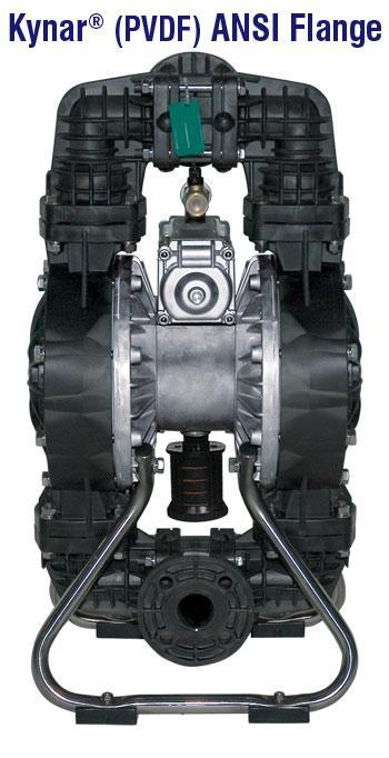
65 Diaphragm Pump 65
66 Hydraulic Machines Major Types of Pumps, contd: 2) Rotary Pumps: Rotary pumps are positive displacement pumps that move fluid by means of screws, progressing cavities, gears, lobes, or vanes turning within a fixed casting. Rotary pumps produce smooth discharge. However, rotary pumps do experience slip, or leakage of some rotational volume back to the suction or intake side. This slip reduces the pump capacity. 66


67 Rotary Pump Types: Vane Type Rotary Pump Circumferential Piston Lobe Type 67
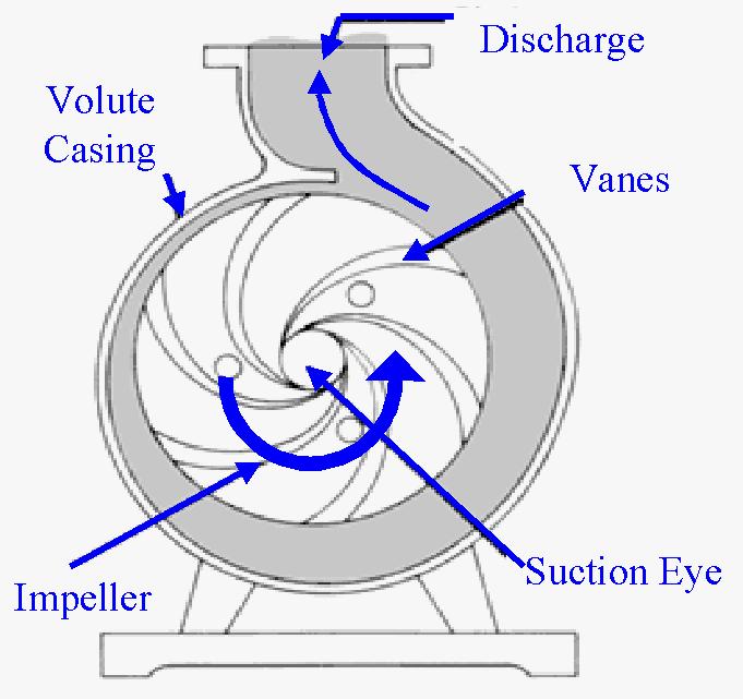
68 Hydraulic Machines; Major Types of Pumps contd: 3) Centrifugal Pumps: Centrifugal pumps are classified according to the way their impellers impart energy to the fluid. Speed range and specific application determine the type of centrifugal pump that should be selected. Centrifugal pumps are commonly used to move liquids through a piping system. The fluid enters the pump impeller along or near to the rotating axis and is accelerated by the impeller, flowing radially outward into a diffuser chamber, from where it exits into the downstream piping system. A centrifugal works on the principle of conversion of the kinetic energy of a flowing fluid (velocity pressure) into static pressure. Centrifugal pumps and reciprocating pumps are used extensively for pumping sludge. 68
69 Centrifugal Pump: 69
 Axial Flow: Axial flow impellers impart energy to the fluid in form of pressure energy through compression.")
70 Hydraulic Machines, Major Types of Pumps, contd. Some of the centrifugal pump types are listed below: a) Radial Flow: Suitable for adding high pressure at low flow rates. Radial flow pumps can be single or double suction type. b) Axial Flow: Axial flow impellers impart energy to the fluid in form of pressure energy through compression. Suitable for adding low pressures at high fluid flow rates. 70
71 Hydraulic Machines Hydraulic Machine Formulae & Terminology : Circular Blade Pitch: Circular blade pitch is the impeller s circumference divided by the number of impeller vanes. Impeller Tip Speed, v tip : Impeller tip speed is the tangential velocity at the periphery of the impeller and is a function of impeller diameter and rotational speed. V tip =. D. n / 60 sec/min = D. ω / 2 Where, D = Diameter of the impeller n = Rotational speed in rpm ω = Angular speed in rads/sec 71
72 Hydraulic Machines Hydraulic Machine Formulae & Terminology, contd: Suction: Suction is the inlet point of a pump. Suction end parameters are subscripted with s. Discharge: Discharge is the outlet point of a pump. Discharge end parameters are subscripted with d. Friction Head, h f : Friction Head is the head required to overcome the resistance offered to flow of fluid in pipes, fittings, elbows, valves, entrances and exits. H f = (f. L. V 2 ) / (2. D. g) { Darcy Equation } 72
73 Hydraulic Machines Hydraulic Machine Formulae & Terminology, contd: Velocity Head, h v : The specific kinetic energy of the fluid. The velocity head is also referred to as dynamic head. h v = v 2 /2g Static Suction Head, h z(s) : Static Suction Head is defined as the vertical distance above the centerline of the pump inlet to the level of fluid in the reservoir. 73
74 Static Suction Head & Static Suction Lift Static Suction Head, h z(s) : Static Suction Lift, - h z(s 74
75 Static Discharge Head Static Discharge Head, h z(d) 75
76 77
77 78
78 Hydraulic Machines - Formulae & Terminology, contd: Hydraulic machine parameters such as power factor, motor efficiency, motor input horsepower (EHp), brake horsepower (BHp), hydraulic horsepower (WHp), total efficiency, and pump efficiency are typically calculated or retrieved through reference tables. Additional Definitions: Head - a measure of the pressure or force exerted by the fluid. Power input - the electrical input to the motor expressed in kilowatts (kw). A measure of the rate at which work is done. Power factor - the ratio of the true power to the volt-amperes in an alternation current (ac) circuit. Motor efficiency - a measure of how effectively the motor turns electrical energy into mechanical energy. It is the ratio of power input to power output. 79
79 Hydraulic Machines - Formulae & Terminology, contd: Motor input horsepower (EHp) - the power input to the motor expressed in horsepower. Brake horsepower (BHp) - the power delivered to the pump shaft expressed in horsepower. Hydraulic horsepower (WHp) - the pump output or the liquid horsepower delivered by the pump. Total efficiency - the ratio of the energy delivered by the pump to the energy supplied to the input side of the motor. Sometimes refered to as the wire to water efficiency. Pump efficiency - the ratio of the energy delivered by the pump to the energy supplied to the pump shaft. 80

80 Efficiency & Power Delivery Stages Electrical Power from Utility EHP > BHP > WHP Motor Eff. motor Pump Efficiency, pump HP, Delivered by the Utility to the Motor HP Del. By Utility = BHP / motor BHP, Delivered by the Motor to the Pump BHP = WHP / pump WHP, Delivered by the Pump to the Fluid Note: For a steam or hydro based electric power generating system, the power flow would be the reverse of the sequence depicted above. See Problem 9. 81
81 Machine Formulas & Terminology, contd: Pumping Power Formulas, contd: 2. Pumping Horsepower as a function of the head added, h A, volumetric flow rate, Q, and the Specific Gravity, SG : When h A is given in ft, Q, in gal/min, Pumping Power P p, in hp, can be calculated using the following equation: Hydraulic Horsepower = WHP, Water Horsepower : P p = h A. Q. SG / Eq. 2(a) 83
82 Hydraulic Machine Formulas & Terminology, contd: Pumping Power Formulas, contd: 3. Pumping Horsepower as a function of the Differential Pressure, P, and the volumetric flow rate, V, in ft 3 / sec : Hydraulic Horsepower = WHP, Water Horsepower : P p = P. V / 550, if P is in psf.. Eq. 3(a) P p = P. V / 3.819, if P is in psi.. Eq. 3(b) 84
83 Hydraulic Machine Formulae & Terminology, contd: Pumping Power Formulas, contd: 4. Pumping Horsepower as a function of W, Work or Energy (Specific) in ft-lbf /lbm and the volumetric flow rate: Hydraulic Horsepower = WHP, Water Horsepower : P p = W. Q. (SG) / 3956; where Q is in gal/min P p = W. ṁ. / 550; where ṁ is in lbm/sec. Eq. 4(a) Eq. 4(b) P p = W. V. (SG) / 8.814; where V is in ft 3 / sec Eq. 4(c) P p = h A. V. (SG) / 8.814; where V is in ft 3 / sec..eq. 4(d) 85
84 Hydraulic Machine Formulas & Terminology, contd: Specific Speed: The capacity and efficiency of a centrifugal pump are, partially, a function of the impeller design. Each impeller design will yield a certain flow rate and added head. The quantitative index used to optimize the impeller design is known as specific speed, n s. n s = n. V / (h A ) SI Units, Eq. SS-1 n s = n. Q / (h A ) US Units, Eq. SS-2 Note: n and n s are in rpm 86
85 Hydraulic Machine Formulas & Terminology, contd: Affinity Laws: If the impeller diameter is held constant and the speed is varied, the following ratios hold true: Q 2 / Q 1 = n 2 /n 1 h 2 /h 1 = (n 2 /n 1 ) 2 P 2 /P 1 = (n 2 /n 1 ) 3.Eq. AF(1) = (Q 2 /Q 1 ) 2...Eq. AF(2) = (Q 2 /Q 1 ) 3...Eq. AF(3) If the impeller speed is held constant and the impeller size is varied, the following ratios hold true: Q 2 / Q 1 = D 2 /D 1... Eq. AF(4) h 2 /h 1 = (D 2 /D 1 ) 2. Eq. AF(5) P 2 /P 1 = (D 2 /D 1 ) 3.. Eq. AF(6) 87
86 BLANK SLIDE 88
87 Problem 8 Case study of an elevated water tower, service pump and a fire pump. The service pump operates at constant 80 gpm. The inline fire pump can draw water, in case of fire, at the rate of 40 gpm. The local fire code requires that the fire pump must be able to sustain the required supply of water for a minimum period of 3 hours. The service demand per hour, for a 24 hour period, is given on the next slide. Calculate or determine the following based on the data provide: a) Maximum flow of water INTO the water tower. b) Average or uniform demand rate for the 24 hour period. c) Maximum flow OUT of the water tower in gpm. d) The hour when maximum water flows OUT of the water tower. e) The hour when the maximum amount of water flows INTO the water tower. f) Required, minimum, water tower volume or storage capacity. 89

88 Problem 8 Elevated Water Tower, EWT Fire Pump, 40 gpm Service Pump, 80 gpm 90
89 Problem 8, contd. a) Maximum flow of water into the water tower occurs when the service demand is the least and the no fire emergency conditions exist. The calculations required for this part and other are premised on conversion of service volumes demanded each hour to respective volumetric flow rates in gpm. This data and the demand to supply deficit for each hour are calculated and tabulated on Table 8.1. The net flow of water into the EWT, under these conditions would be = 80 gpm gpm = gpm { 1400 gph / 60m/h = gpm} 91
90 Problem 8, contd. (b) Average or uniform demand rate for the 24 hour period is determined by summing the total demand over the 24 hour period and dividing by 24, see Table 8.1: = 86,700 gal / 24 hrs / 60 min / hr = gpm (c) The conditions for maximum flow out of the EWT, in gpm, would be as follows, see Table 8.1: Maximum Service Demand, at 1700 hrs, of 8,000 gal, translating into = 8,000 gph / 60 min/hr = gpm Full Demand by the Fire Pump = 40 gpm Therefore, the Max. Flow Out of EWT = = gpm {This is assuming that the supply pump is off line} 92
91 Problem 8, contd. Table 8.1 I II Vol. Flow Rate in Pump Demand Minus Deficit to be Hour Peak Demand GPM Supply Rate Supply Offset by Tank in Gallons Gallons Ea. Hr. Stg. Capacity 0 1, , , , , , , , , , , , , , , , , , , (100) , (200) , (1,200) 1, , (700) , (1,700) 1, , (1,800) 1, , (1,900) 1, , (3,200) 3, , , , , , , , , , , , ,400 86,700 10,800 Gallons 93
92 Problem 8, contd. (d) The hour when maximum water flows OUT of the water tower is 1700 hrs, see Table 8.1, at the rate of gpm. (e) The hour when the maximum amount of water flows INTO the water tower are 0000, 0100, 0200 & 2300 hrs, see Table 8.1, at the rate of gpm. (f) Required EWT storage capacity: The minimum required EWT storage capacity would have to comply with 3 hour fire pump supply code and must meet the service demand during the supply demand deficit periods; therefore, the EWT capacity components/constituents would be as follows: Volume of water required to operate the fire pump for 3 - hours: = 3 hrs x 40 gpm x 60 min/hr = 7200 gallons 94
 deficit hours.")
93 Problem 8, part (f), contd. The EWT must have the capacity to meet the short fall during the periods when demand exceeds pump capacity. See Table 8.1. The deficit periods span from 1000 hrs through 1700 hours. The last column in the table lists the specific deficits associated with each of the eight (8) deficit hours. The total deficit from the last column in table 8.1 is = 10,800 gallons 95
94 Problem 8, part (f), contd. There fore the minimum required capacity of the EWT would be: = 10,800 gallons + 7,200 gallons = 18,000 gallons or = cu-ft. In other words, you would specify a water tank with the following radius: Since the EWT Capacity or volume is = 2, cu-ft And the volume of a sphere is = 4/3 x ᴨ x r 3 Radius of the EWT would be = r = 8.31 ft 96
95 Problem 9 Pressures on the intake and exit ends of a turbine are measured to be 50 psia and 10 psia, respectively. The volumetric flow rate for the fluid (water) is 120 ft 3 /sec. The turbine is driving a electric generator with nameplate efficiency of 90%. Calculate the following: a) Water Horsepower delivered by the water to the turbine. b) Brake Horsepower delivered by the turbine to the shaft driving the generator. The efficiency of the turbine is 65%. c) Maximum power generated, in KW s, by this hydroelectric power generating system. 97
96 Problem 9 Given: P in = 50 psia P out = 10 psia P = 40 psia P Conv. to psf = 40 lb/in 2 x 144 in 2 / ft 2 = 5760 psf V = Volumetric Flow Rate = 120 cu-ft / sec Turbine Efficiency = 65 % Generator Efficiency = 90 % a) WHP = Water Horsepower delivered by the water to the turbine: WHP = P p = P. V / 550, if P is in psf Eq. 3(a) P p = 5760 lbf/ft ft 3 /sec / 550 = hp 98
97 Problem 9, contd. b) Brake Horsepower delivered by the turbine to the shaft driving the generator; the turbine efficiency is 65%: BHP = WHP x Turbine Efficiency = hp x 0.65 = hp c) Maximum power generated, in kw s, by this hydroelectric power generating system : Power Generated By The Hydro Elect. Power System, in kw's = BHP x Eff. x kw / hp = hp x 0.9 x = kw 99
98 Problem 10 Consider a hydroelectric reservoir where water is flowing through the turbine at the rate of 1100 ft3 / sec. The turbine exit point is 700 ft lower than the elevation of the reservoir water surface. The turbine efficiency is 90% and the total frictional head loss through the shaft (Draft Tube) and turbine system is 52 ft. a) Calculate the power output of the turbine in MW's. b) If the efficiency of the Electric Power Generator is 92%, what would the electric power output be for this hydroelectric power generating system? Given: specific weight = 62.4 lbf / ft 3 h f = 52 ft h z = 700 ft h A = h z - h f = 648 ft V = 1100 cu-ft / sec Turbine Efficiency 90 % Generator Efficiency 92 % 100
99 Problem 10, contd. a) Calculate the power output of the turbine in MW's. P p (in hp) = ( h A.. V ) / 550 Eq. 1(a) P p = WHP = Hydraulic Horsepower = (648 x 62.4 x 1100 ) / 550 = 80,870 hp P out = Power Output of the Turbine = (0.90 x 80,870) = 72,783 hp P out = Power Output of the Turbine in MW = ( 72,783 x ) / 1000 kw per MW = 54 MW 101
100 Problem 10, contd. b) If the efficiency of the Electric Power Generator is 92%, what would the electric power output be for this hydroelectric power generating system? P Gen-out = Power Output of the Generator in MW = ( 54 MW x 0.92 ) = 50 MW 102
101 Problem 11 Consider a hydraulic machine application scenario where the system performance requirement is governed by the mathematical expression: H = 50 + Q 2. Where H represents the required system head in ft. and Q is the volumetric flow rate in cu-ft / sec. The scenario considers and compares two (2) pumps of different size. The pump performance curves for these two pumps are shown in figure 11(a). These performance curves represent operation at 1400 rpm. a) Determine the flow rate Q for Pump - 1 when it is operating at 1400 rpm, to meet the system head requirement. b) What would the system head be at the performance point in part (a)? c) Determine the flow rate Q for Pump - 2 when it is operating at 1400 rpm. 103
102 Problem 11 d) What would the system head be, with Pump - 2, at the performance point in part (c)? e) Calculate the Brake Horse Power, in hp, required to drive Pump - 1, under part (a) conditions. f) If Pump -1 is powered by a VFD and the shaft speed is reduced to 1200 rpm, what would the new flow rate be in the system? g) Which pump would you select for your application if a head of approx. 220 ft is required at a volumetric flow rate of 10 cu-ft/sec.? 104
 = 50 + Q 2 Fig. 11(a), Q vs. h A Q: Flow Rate System Head, H s 0 50 2 54 5 75 7 99 10 150 15 275 20 450 25 675 30 950 35 1275 Head, H, in ft.")
103 Problem 11 a) Determine the flow rate Q for Pump - 1 when it is operating at 1400 rpm, to meet the system head requirement. Given: Conversion Factor: gpm per cu-ft/sec System Head Requirement Eq.: H (Q) = 50 + Q 2 Fig. 11(a), Q vs. h A Q: Flow Rate System Head, H s Head, H, in ft. 250 (g) The Pump Performance Curves are Based on 1400 rpm Operation System & Pump Curve Pump #1 Perf. Curve Pump #2 Perf. Curve 0 13 cuft/sec 0 11 cuft/sec Q, Flow Rate in cu-ft./sec 105
104 Problem 11, contd. a) Determine the flow rate for Pump - 1, at the required system head, when it is operating at 1400 rpm Identify the point on the graph at which Pump-1's performance curve intersects with the system head requirement curve. Extrapolate a line (dashed line on the graph) to the horizontal axis representing Q, in Cu-ft./sec. The projected line intersects the Q- axis at 11 cu-ft/sec. Therefore, the required flow rate Q: = Q, in gals/min, or, gpm = 11 cu-ft/sec 106
105 Problem 11, contd. b) System Head at the performance point in part (a), at Q of 11 cuft./sec = H (Q) = 50 + Q 2 = 171 ft c) Determine the flow rate Q for Pump - 2 when it is operating at 1400 rpm. Identify the point on the graph at which Pump-2's performance curve intersects with the system head requirement curve. Extrapolate a line (dashed line on the graph) to the horizontal axis representing Q, in cu-ft./sec. The projected line intersects the Q- axis at 13 cu-ft/sec. Therefore, the required flow rate, Q = 13 cu-ft/sec Q, in gals/min, or, gpm = 13 cu-ft/sec x gpm/(cu-ft/sec) = 5,834 gpm 107
106 Problem 11, contd. d) System Head at the performance point in part (a), at Q of 13 cuft/sec = H (Q) = 50 + Q 2 = 219 ft e) Calculate the Brake Horse Power, in hp, required to drive Pump - 1, under conditions stated in part (a). Approach: Calculate the WHP, Water Horse Power, first, using Eq. 4 (d); then derive the BHP using the pump efficiency. The pump efficiency is not given and must be retrieved from the given pump curve. Since, WHP = P p = h A. V. (SG) / 8.814; the power that needs to be delivered to the fluid. h A, as calculated in part (b) = 171 ft. V, as determined in part (a) = 11 cu-ft/sec,or = 4937 gpm SG for water = 1 108
107 Problem 11, contd. Part (e) contd. n = 1400 rpm Therefore, WHP = P p = h A. V. (SG) / WHP = P p = 213 hp Now, BHP = WHP / Eff. p The pump efficiency Eff. p can be obtained through the Specific Speed Pump Efficiency curve "E." From equation SS-2, the Specific Speed is: n s = n. Q / (h A ) 0.75 Where, n and n s are in "rpm", Q is in "gpm" and h A is in "ft Therefore, n s = ,937/ (171) 0.75 or, n s = 2080 rpm Then, from Pump Efficiency curve "E," the pump efficiency = 87.5% Hence, BHP = WHP / Eff. p = 213 / = 244 hp 109

108 Problem 11, contd. Specific Speed vs. Pump Efficiency Curve 110
109 Problem 11, contd. f) If Pump -1 is powered by a VFD and the shaft speed is reduced to 1200 rpm, what would the new flow rate be in the system? From Affinity Laws; Equation AF (1): Q 2 /Q 1 = n 2 /n 1 and Q 2 = (n 2 /n 1 ). Q 1 Given and as calculated earlier: Q 1 = 4937 n 1 = 1400 n 2 = 1200 Therefore, Q 2 = (n 2 /n 1 ). Q 1 = (1200/1400) x 4937 = 4232 gpm 111
110 Problem 11, contd. g) Which pump would you select for your application if a head of approx. 220 ft is required at a volumetric flow rate of 10 cu-ft/sec.? The question is premised on the assumption that the system head curve has changed such that it passes through a point on the graph where Q = 10 cu-ft/sec and the head h A is approximately 220 ft. By inspection of the Q vs. h A graph, figure 11 (a), we can see that Pump #1 is capable of providing only 185 ft at Q of 10 cu-ft/sec. Therefore, Pump #2 would be more suitable for meeting the specified requirement. 112
FE Fluids Review March 23, 2012 Steve Burian (Civil & Environmental Engineering)
") Topic: Fluid Properties 1. If 6 m 3 of oil weighs 47 kn, calculate its specific weight, density, and specific gravity. 2. 10.0 L of an incompressible liquid exert a force of 20 N at the earth s surface.
Topic: Fluid Properties 1. If 6 m 3 of oil weighs 47 kn, calculate its specific weight, density, and specific gravity. 2. 10.0 L of an incompressible liquid exert a force of 20 N at the earth s surface.
Applied Fluid Mechanics
 Applied Fluid Mechanics 1. The Nature of Fluid and the Study of Fluid Mechanics 2. Viscosity of Fluid 3. Pressure Measurement 4. Forces Due to Static Fluid 5. Buoyancy and Stability 6. Flow of Fluid and
CHAPTER EIGHT P U M P I N G O F L I Q U I D S
 CHAPTER EIGHT P U M P I N G O F L I Q U I D S Pupmps are devices for supplying energy or head to a flowing liquid in order to overcome head losses due to friction and also if necessary, to raise liquid
Atmospheric pressure. 9 ft. 6 ft
 Name CEE 4 Final Exam, Aut 00; Answer all questions; 145 points total. Some information that might be helpful is provided below. A Moody diagram is printed on the last page. For water at 0 o C (68 o F):
Lesson 6 Review of fundamentals: Fluid flow
 Lesson 6 Review of fundamentals: Fluid flow The specific objective of this lesson is to conduct a brief review of the fundamentals of fluid flow and present: A general equation for conservation of mass
TOTAL HEAD, N.P.S.H. AND OTHER CALCULATION EXAMPLES Jacques Chaurette p. eng., June 2003
 TOTAL HEAD, N.P.S.H. AND OTHER CALCULATION EXAMPLES Jacques Chaurette p. eng., www.lightmypump.com June 2003 Figure 1 Calculation example flow schematic. Situation Water at 150 F is to be pumped from a
Northern Lesson 2 Gear Pump Terminology. Gear Pump 101. Lesson 2: Gear Pump Terminology. When your reputation depends on it!
 Gear Pump 101 Lesson 2: Gear Pump Terminology When your reputation depends on it! Symbol Term Metric Unit Abbreviation US Customary Unit Abbreviation Conversion factor a A Area square millimeter mm2 square
9. Pumps (compressors & turbines) Partly based on Chapter 10 of the De Nevers textbook.
 Partly based on Chapter 10 of the De Nevers textbook.") Lecture Notes CHE 31 Fluid Mechanics (Fall 010) 9. Pumps (compressors & turbines) Partly based on Chapter 10 of the De Nevers textbook. Basics (pressure head, efficiency, working point, stability) Pumps
Lecture Notes CHE 31 Fluid Mechanics (Fall 010) 9. Pumps (compressors & turbines) Partly based on Chapter 10 of the De Nevers textbook. Basics (pressure head, efficiency, working point, stability) Pumps
Chapter 7 The Energy Equation
 Chapter 7 The Energy Equation 7.1 Energy, Work, and Power When matter has energy, the matter can be used to do work. A fluid can have several forms of energy. For example a fluid jet has kinetic energy,
WATER DISTRIBUTION NETWORKS
 WATER DISTRIBUTION NETWORKS CE 370 1 Components of Water Supply System 2 1 Water Distribution System Water distribution systems are designed to adequately satisfy the water requirements for a combinations
FE Exam Fluids Review October 23, Important Concepts
 FE Exam Fluids Review October 3, 013 mportant Concepts Density, specific volume, specific weight, specific gravity (Water 1000 kg/m^3, Air 1. kg/m^3) Meaning & Symbols? Stress, Pressure, Viscosity; Meaning
Chapter Four fluid flow mass, energy, Bernoulli and momentum
 4-1Conservation of Mass Principle Consider a control volume of arbitrary shape, as shown in Fig (4-1). Figure (4-1): the differential control volume and differential control volume (Total mass entering
Pressure and Flow Characteristics
 Pressure and Flow Characteristics Continuing Education from the American Society of Plumbing Engineers August 2015 ASPE.ORG/ReadLearnEarn CEU 226 READ, LEARN, EARN Note: In determining your answers to
Hydraulics. B.E. (Civil), Year/Part: II/II. Tutorial solutions: Pipe flow. Tutorial 1
, Year/Part: II/II. Tutorial solutions: Pipe flow. Tutorial 1") Hydraulics B.E. (Civil), Year/Part: II/II Tutorial solutions: Pipe flow Tutorial 1 -by Dr. K.N. Dulal Laminar flow 1. A pipe 200mm in diameter and 20km long conveys oil of density 900 kg/m 3 and viscosity
Hydraulics B.E. (Civil), Year/Part: II/II Tutorial solutions: Pipe flow Tutorial 1 -by Dr. K.N. Dulal Laminar flow 1. A pipe 200mm in diameter and 20km long conveys oil of density 900 kg/m 3 and viscosity
Mechanical Engineering Programme of Study
 Mechanical Engineering Programme of Study Fluid Mechanics Instructor: Marios M. Fyrillas Email: eng.fm@fit.ac.cy SOLVED EXAMPLES ON VISCOUS FLOW 1. Consider steady, laminar flow between two fixed parallel
Basic Math Concepts for Water and Wastewater Operators. Daniel B. Stephens & Associates, Inc.
 Basic Math Concepts for Water and Wastewater Operators Topics Hierarchy of operations Manipulating equations Unit/dimensional analysis and conversion factors Electricity Temperature Geometry Flow hydraulics
REE 307 Fluid Mechanics II. Lecture 1. Sep 27, Dr./ Ahmed Mohamed Nagib Elmekawy. Zewail City for Science and Technology
 REE 307 Fluid Mechanics II Lecture 1 Sep 27, 2017 Dr./ Ahmed Mohamed Nagib Elmekawy Zewail City for Science and Technology Course Materials drahmednagib.com 2 COURSE OUTLINE Fundamental of Flow in pipes
Figure 3: Problem 7. (a) 0.9 m (b) 1.8 m (c) 2.7 m (d) 3.6 m
 0.9 m (b) 1.8 m (c) 2.7 m (d) 3.6 m") 1. For the manometer shown in figure 1, if the absolute pressure at point A is 1.013 10 5 Pa, the absolute pressure at point B is (ρ water =10 3 kg/m 3, ρ Hg =13.56 10 3 kg/m 3, ρ oil = 800kg/m 3 ): (a)
1. For the manometer shown in figure 1, if the absolute pressure at point A is 1.013 10 5 Pa, the absolute pressure at point B is (ρ water =10 3 kg/m 3, ρ Hg =13.56 10 3 kg/m 3, ρ oil = 800kg/m 3 ): (a)
Reynolds, an engineering professor in early 1880 demonstrated two different types of flow through an experiment:
 7 STEADY FLOW IN PIPES 7.1 Reynolds Number Reynolds, an engineering professor in early 1880 demonstrated two different types of flow through an experiment: Laminar flow Turbulent flow Reynolds apparatus
ME3560 Tentative Schedule Spring 2019
 ME3560 Tentative Schedule Spring 2019 Week Number Date Lecture Topics Covered Prior to Lecture Read Section Assignment Prep Problems for Prep Probs. Must be Solved by 1 Monday 1/7/2019 1 Introduction to
CHAPTER TWO CENTRIFUGAL PUMPS 2.1 Energy Transfer In Turbo Machines
 7 CHAPTER TWO CENTRIFUGAL PUMPS 21 Energy Transfer In Turbo Machines Fig21 Now consider a turbomachine (pump or turbine) the total head (H) supplied by it is The power delivered to/by the fluid simply
Chapter 8: Flow in Pipes
 Objectives 1. Have a deeper understanding of laminar and turbulent flow in pipes and the analysis of fully developed flow 2. Calculate the major and minor losses associated with pipe flow in piping networks
When water (fluid) flows in a pipe, for example from point A to point B, pressure drop will occur due to the energy losses (major and minor losses).
 flows in a pipe, for example from point A to point B, pressure drop will occur due to the energy losses (major and minor losses).") PRESSURE DROP AND OSSES IN PIPE When water (luid) lows in a pipe, or example rom point A to point B, pressure drop will occur due to the energy losses (major and minor losses). A B Bernoulli equation:
PRESSURE DROP AND OSSES IN PIPE When water (luid) lows in a pipe, or example rom point A to point B, pressure drop will occur due to the energy losses (major and minor losses). A B Bernoulli equation:
ME3560 Tentative Schedule Fall 2018
 ME3560 Tentative Schedule Fall 2018 Week Number 1 Wednesday 8/29/2018 1 Date Lecture Topics Covered Introduction to course, syllabus and class policies. Math Review. Differentiation. Prior to Lecture Read
SUMMER 14 EXAMINATION
 Important Instructions to examiners: 1) The answers should be examined by key words and not as word-to-word as given in the model answer scheme. 2) The model answer and the answer written by candidate
PUMP SYSTEM ANALYSIS AND SIZING. BY JACQUES CHAURETTE p. eng.
 PUMP SYSTEM ANALYSIS AND SIZING BY JACQUES CHAURETTE p. eng. 5 th Edition February 2003 Published by Fluide Design Inc. www.fluidedesign.com Copyright 1994 I TABLE OF CONTENTS Introduction Symbols Chapter
Universität Duisburg-Essen Fakultät für Ingenieurwissenschaften WS 2012 Maschinenbau, IVG, Thermodynamik Dr. M. A. Siddiqi
 1 Universität Duisburg-Essen 3. Semester Fakultät für Ingenieurwissenschaften WS 2012 Maschinenbau, IVG, Thermodynamik Dr. M. A. Siddiqi THERMODYNAMICS LAB (ISE) Pressure Measurement 2 2 Pressure Measurement
Chapter Four Hydraulic Machines
 Contents 1- Introduction. 2- Pumps. Chapter Four Hydraulic Machines (لفرع الميكانيك العام فقط ( Turbines. -3 4- Cavitation in hydraulic machines. 5- Examples. 6- Problems; sheet No. 4 (Pumps) 7- Problems;
COURSE CODE : 3072 COURSE CATEGORY : B PERIODS/ WEEK : 5 PERIODS/ SEMESTER : 75 CREDIT : 5 TIME SCHEDULE
 COURSE TITLE : FLUID MECHANICS COURSE CODE : 307 COURSE CATEGORY : B PERIODS/ WEEK : 5 PERIODS/ SEMESTER : 75 CREDIT : 5 TIME SCHEDULE MODULE TOPIC PERIOD 1 Properties of Fluids 0 Fluid Friction and Flow
Fluid Mechanics. du dy
 FLUID MECHANICS Technical English - I 1 th week Fluid Mechanics FLUID STATICS FLUID DYNAMICS Fluid Statics or Hydrostatics is the study of fluids at rest. The main equation required for this is Newton's
ACCOUNTING FOR FRICTION IN THE BERNOULLI EQUATION FOR FLOW THROUGH PIPES
 ACCOUNTING FOR FRICTION IN THE BERNOULLI EQUATION FOR FLOW THROUGH PIPES Some background information first: We have seen that a major limitation of the Bernoulli equation is that it does not account for
vector H. If O is the point about which moments are desired, the angular moment about O is given:
 The angular momentum A control volume analysis can be applied to the angular momentum, by letting B equal to angularmomentum vector H. If O is the point about which moments are desired, the angular moment
Chapter Four Hydraulic Machines
 Contents 1- Introduction. - Pumps. Chapter Four Hydraulic Machines (لفرع الميكانيك العام فقط ( Turbines. -3 4- Cavitation in hydraulic machines. 5- Examples. 6- Problems; sheet No. 4 (Pumps) 7- Problems;
LECTURE 6- ENERGY LOSSES IN HYDRAULIC SYSTEMS SELF EVALUATION QUESTIONS AND ANSWERS
 LECTURE 6- ENERGY LOSSES IN HYDRAULIC SYSTEMS SELF EVALUATION QUESTIONS AND ANSWERS 1. What is the head loss ( in units of bars) across a 30mm wide open gate valve when oil ( SG=0.9) flow through at a
INSTITUTE OF AERONAUTICAL ENGINEERING Dundigal, Hyderabad AERONAUTICAL ENGINEERING QUESTION BANK : AERONAUTICAL ENGINEERING.
 Course Name Course Code Class Branch INSTITUTE OF AERONAUTICAL ENGINEERING Dundigal, Hyderabad - 00 0 AERONAUTICAL ENGINEERING : Mechanics of Fluids : A00 : II-I- B. Tech Year : 0 0 Course Coordinator
CIVE HYDRAULIC ENGINEERING PART II Pierre Julien Colorado State University
 1 CIVE 401 - HYDRAULIC ENGINEERING PART II Pierre Julien Colorado State University Problems with and are considered moderate and those with are the longest and most difficult. In 2018 solve the problems
Therefore, the control volume in this case can be treated as a solid body, with a net force or thrust of. bm # V
 When the mass m of the control volume remains nearly constant, the first term of the Eq. 6 8 simply becomes mass times acceleration since 39 CHAPTER 6 d(mv ) CV m dv CV CV (ma ) CV Therefore, the control
4 Mechanics of Fluids (I)
") 1. The x and y components of velocity for a two-dimensional flow are u = 3.0 ft/s and v = 9.0x ft/s where x is in feet. Determine the equation for the streamlines and graph representative streamlines in
1. The x and y components of velocity for a two-dimensional flow are u = 3.0 ft/s and v = 9.0x ft/s where x is in feet. Determine the equation for the streamlines and graph representative streamlines in
NEBB Fundamental Formulas
 Approved NEBB - May 1, 17 Page 1 of 8 Version 1.3 A = Area (ft²) IP, (m²) SI M = Mass (lb) IP, (kg) SI ACH = Air Changes per Hour ma = Mixed Air Ak = Effective Area m = meter (metre) AV = Average m³/s
CENTRIFUGAL PUMP SELECTION, SIZING, AND INTERPRETATION OF PERFORMANCE CURVES
 CENTRIFUGAL PUMP SELECTION, SIZING, AND INTERPRETATION OF PERFORMANCE CURVES 4.0 PUMP CLASSES Pumps may be classified in two general types, dynamic and positive displacement. Positive displacement pumps
s and FE X. A. Flow measurement B. properties C. statics D. impulse, and momentum equations E. Pipe and other internal flow 7% of FE Morning Session I
 Fundamentals of Engineering (FE) Exam General Section Steven Burian Civil & Environmental Engineering October 26, 2010 s and FE X. A. Flow measurement B. properties C. statics D. impulse, and momentum
where = rate of change of total energy of the system, = rate of heat added to the system, = rate of work done by the system
 The Energy Equation for Control Volumes Recall, the First Law of Thermodynamics: where = rate of change of total energy of the system, = rate of heat added to the system, = rate of work done by the system
TOPICS. Density. Pressure. Variation of Pressure with Depth. Pressure Measurements. Buoyant Forces-Archimedes Principle
 Lecture 6 Fluids TOPICS Density Pressure Variation of Pressure with Depth Pressure Measurements Buoyant Forces-Archimedes Principle Surface Tension ( External source ) Viscosity ( External source ) Equation
CLASS Fourth Units (Second part)
") CLASS Fourth Units (Second part) Energy analysis of closed systems Copyright The McGraw-Hill Companies, Inc. Permission required for reproduction or display. MOVING BOUNDARY WORK Moving boundary work (P
CLASS Fourth Units (Second part) Energy analysis of closed systems Copyright The McGraw-Hill Companies, Inc. Permission required for reproduction or display. MOVING BOUNDARY WORK Moving boundary work (P
New Website: M P E il Add. Mr. Peterson s Address:
 Brad Peterson, P.E. New Website: http://njut009fall.weebly.com M P E il Add Mr. Peterson s Email Address: bradpeterson@engineer.com If 6 m 3 of oil weighs 47 kn calculate its If 6 m 3 of oil weighs 47
Chapter (6) Energy Equation and Its Applications
 Energy Equation and Its Applications") Chapter (6) Energy Equation and Its Applications Bernoulli Equation Bernoulli equation is one of the most useful equations in fluid mechanics and hydraulics. And it s a statement of the principle of conservation
Chapter (6) Energy Equation and Its Applications Bernoulli Equation Bernoulli equation is one of the most useful equations in fluid mechanics and hydraulics. And it s a statement of the principle of conservation
Dr. S. Ramachandran Prof. R. Devaraj. Mr. YVS. Karthick AIR WALK PUBLICATIONS
 Fluid Machinery As per Revised Syllabus of Leading Universities including APJ ABDUL KALAM TECHNOLOGICAL UNIVERSITY Dr. S. Ramachandran Prof. R. Devaraj Professors School of Mechanical Engineering Sathyabama
Properties and Definitions Useful constants, properties, and conversions
 Properties and Definitions Useful constants, properties, and conversions gc = 32.2 ft/sec 2 [lbm-ft/lbf-sec 2 ] ρwater = 1.96 slugs/ft 3 γwater = 62.4 lb/ft 3 1 ft 3 /sec = 449 gpm 1 mgd = 1.547 ft 3 /sec
CHAPTER 3 BASIC EQUATIONS IN FLUID MECHANICS NOOR ALIZA AHMAD
 CHAPTER 3 BASIC EQUATIONS IN FLUID MECHANICS 1 INTRODUCTION Flow often referred as an ideal fluid. We presume that such a fluid has no viscosity. However, this is an idealized situation that does not exist.
M E 320 Professor John M. Cimbala Lecture 24
 M E 30 Professor John M. Cimbala Lecture 4 Today, we will: Discuss pump performance curves Discuss how to match a pump and a piping system, and do some example problems. Pump Performance a. Pump performance
Chapter 6. Losses due to Fluid Friction
 Chapter 6 Losses due to Fluid Friction 1 Objectives ä To measure the pressure drop in the straight section of smooth, rough, and packed pipes as a function of flow rate. ä To correlate this in terms of
PIPING SYSTEMS. Pipe and Tubing Standards Sizes for pipes and tubes are standardized. Pipes are specified by a nominal diameter and a schedule number.
 PIPING SYSTEMS In this chapter we will review some of the basic concepts associated with piping systems. Topics that will be considered in this chapter are - Pipe and tubing standards - Effective and hydraulic
Part A: 1 pts each, 10 pts total, no partial credit.
 Part A: 1 pts each, 10 pts total, no partial credit. 1) (Correct: 1 pt/ Wrong: -3 pts). The sum of static, dynamic, and hydrostatic pressures is constant when flow is steady, irrotational, incompressible,
EXPERIMENT No.1 FLOW MEASUREMENT BY ORIFICEMETER
 EXPERIMENT No.1 FLOW MEASUREMENT BY ORIFICEMETER 1.1 AIM: To determine the co-efficient of discharge of the orifice meter 1.2 EQUIPMENTS REQUIRED: Orifice meter test rig, Stopwatch 1.3 PREPARATION 1.3.1
Basic Fluid Mechanics
 Basic Fluid Mechanics Chapter 5: Application of Bernoulli Equation 4/16/2018 C5: Application of Bernoulli Equation 1 5.1 Introduction In this chapter we will show that the equation of motion of a particle
Rate of Flow Quantity of fluid passing through any section (area) per unit time
 per unit time") Kinematics of Fluid Flow Kinematics is the science which deals with study of motion of liquids without considering the forces causing the motion. Rate of Flow Quantity of fluid passing through any section
Kinematics of Fluid Flow Kinematics is the science which deals with study of motion of liquids without considering the forces causing the motion. Rate of Flow Quantity of fluid passing through any section
Hydraulics for Urban Storm Drainage
 Urban Hydraulics Hydraulics for Urban Storm Drainage Learning objectives: understanding of basic concepts of fluid flow and how to analyze conduit flows, free surface flows. to analyze, hydrostatic pressure
n = Kinematic viscosity (cst) SG = specific gravity or 1 Poise = 100 cp 1 Stoke = 100 cst Q = capacity (m 3 /s) A = tube area (m 2 ) or
 SG = specific gravity or 1 Poise = 100 cp 1 Stoke = 100 cst Q = capacity (m 3 /s) A = tube area (m 2 ) or") Fmulas Designation Fmula Comments Product Viscosity n = m r n = Kinematic viscosity (mm /s) m = Absolute viscosity (mpa.s) n = m SG n = Kinematic viscosity (cst) m = Absolute viscosity (cp) m = n SG 1
Fmulas Designation Fmula Comments Product Viscosity n = m r n = Kinematic viscosity (mm /s) m = Absolute viscosity (mpa.s) n = m SG n = Kinematic viscosity (cst) m = Absolute viscosity (cp) m = n SG 1
Hydroelectric Design
 INTERAMERICAN UNIVERSITY OF BAYAMON PUERTO RICO Hydroelectric Design Dr. Eduardo G. Pérez Díaz Erik T. Rosado González 5/14/2012 Hydroelectric design project for fluid class. TABLE OF CONTENTS TABLE OF
Pumping Stations Design For Infrastructure Master Program Engineering Faculty-IUG
 umping Stations Design For Infrastructure Master rogram Engineering Faculty-IUG Lecture : umping Hydraulics Dr. Fahid Rabah Water and environment Engineering frabah@iugaza.edu The main items that will
M E 320 Professor John M. Cimbala Lecture 23
 M E 320 Professor John M. Cimbala Lecture 23 Today, we will: Discuss diffusers and do an example problem Begin discussing pumps, and how they are analyzed in pipe flow systems D. Diffusers 1. Introduction.
MOTOR WIRING DATA From National Electrical Code 3 PHASE SQUIRREL CAGE INDUCTION MOTORS 230 Volt 460 Volt Min. # Max. Rating
 MOTOR WIRING DATA From National Electrical Code PHASE SQUIRREL CAGE INDUCTION MOTORS 20 Volt 0 Volt Min. # Max. Rating Min. Size Size of Full Size Wire Conduit Branch Circuit Load Wire AWG (inches) Fuses
5 ENERGY EQUATION OF FLUID MOTION
 5 ENERGY EQUATION OF FLUID MOTION 5.1 Introduction In order to develop the equations that describe a flow, it is assumed that fluids are subject to certain fundamental laws of physics. The pertinent laws
 CE 6303 MECHANICS OF FLUIDS L T P C QUESTION BANK 3 0 0 3 UNIT I FLUID PROPERTIES AND FLUID STATICS PART - A 1. Define fluid and fluid mechanics. 2. Define real and ideal fluids. 3. Define mass density
STEADY FLOW THROUGH PIPES DARCY WEISBACH EQUATION FOR FLOW IN PIPES. HAZEN WILLIAM S FORMULA, LOSSES IN PIPELINES, HYDRAULIC GRADE LINES AND ENERGY
 STEADY FLOW THROUGH PIPES DARCY WEISBACH EQUATION FOR FLOW IN PIPES. HAZEN WILLIAM S FORMULA, LOSSES IN PIPELINES, HYDRAULIC GRADE LINES AND ENERGY LINES 1 SIGNIFICANCE OF CONDUITS In considering the convenience
Hydraulics and hydrology
 Hydraulics and hydrology - project exercises - Class 4 and 5 Pipe flow Discharge (Q) (called also as the volume flow rate) is the volume of fluid that passes through an area per unit time. The discharge
Signature: (Note that unsigned exams will be given a score of zero.)
") Neatly print your name: Signature: (Note that unsigned exams will be given a score of zero.) Circle your lecture section (-1 point if not circled, or circled incorrectly): Prof. Dabiri Prof. Wassgren Prof.
Neatly print your name: Signature: (Note that unsigned exams will be given a score of zero.) Circle your lecture section (-1 point if not circled, or circled incorrectly): Prof. Dabiri Prof. Wassgren Prof.
Approximate physical properties of selected fluids All properties are given at pressure kn/m 2 and temperature 15 C.
 Appendix FLUID MECHANICS Approximate physical properties of selected fluids All properties are given at pressure 101. kn/m and temperature 15 C. Liquids Density (kg/m ) Dynamic viscosity (N s/m ) Surface
MODULE CODE: ENGG08021 INTRODUCTION TO THERMOFLUIDS. Date: 15 January 2016 Time: 10:00 12:00
 School of Engineering & Computing Session 2015-16 Paisley Campus Trimester 1 MODULE CODE: ENGG08021 INTRODUCTION TO THERMOFLUIDS Date: 15 January 2016 Time: 10:00 12:00 Attempt FOUR QUESTIONS IN TOTAL
Heat Transfer Convection
 Heat ransfer Convection Previous lectures conduction: heat transfer without fluid motion oday (textbook nearly 00 pages) Convection: heat transfer with fluid motion Research methods different Natural Convection
Chapter 1 INTRODUCTION
 Chapter 1 INTRODUCTION 1-1 The Fluid. 1-2 Dimensions. 1-3 Units. 1-4 Fluid Properties. 1 1-1 The Fluid: It is the substance that deforms continuously when subjected to a shear stress. Matter Solid Fluid
MECHANICAL PROPERTIES OF FLUIDS:
 Important Definitions: MECHANICAL PROPERTIES OF FLUIDS: Fluid: A substance that can flow is called Fluid Both liquids and gases are fluids Pressure: The normal force acting per unit area of a surface is
2 Internal Fluid Flow
 Internal Fluid Flow.1 Definitions Fluid Dynamics The study of fluids in motion. Static Pressure The pressure at a given point exerted by the static head of the fluid present directly above that point.
CE MECHANICS OF FLUIDS
 CE60 - MECHANICS OF FLUIDS (FOR III SEMESTER) UNIT II FLUID STATICS & KINEMATICS PREPARED BY R.SURYA, M.E Assistant Professor DEPARTMENT OF CIVIL ENGINEERING DEPARTMENT OF CIVIL ENGINEERING SRI VIDYA COLLEGE
Viscous Flow in Ducts
 Dr. M. Siavashi Iran University of Science and Technology Spring 2014 Objectives 1. Have a deeper understanding of laminar and turbulent flow in pipes and the analysis of fully developed flow 2. Calculate
Chapter 6. Losses due to Fluid Friction
 Chapter 6 Losses due to Fluid Friction 1 Objectives To measure the pressure drop in the straight section of smooth, rough, and packed pipes as a function of flow rate. To correlate this in terms of the
Introduction to Fluid Machines, and Compressible Flow Prof. S. K. Som Department of Mechanical Engineering Indian Institute of Technology, Kharagpur
 Introduction to Fluid Machines, and Compressible Flow Prof. S. K. Som Department of Mechanical Engineering Indian Institute of Technology, Kharagpur Lecture - 09 Introduction to Reaction Type of Hydraulic
Chapter 4 DYNAMICS OF FLUID FLOW
 Faculty Of Engineering at Shobra nd Year Civil - 016 Chapter 4 DYNAMICS OF FLUID FLOW 4-1 Types of Energy 4- Euler s Equation 4-3 Bernoulli s Equation 4-4 Total Energy Line (TEL) and Hydraulic Grade Line
F L U I D S Y S T E M D Y N A M I C S
 F L U I D S Y S T E M D Y N A M I C S T he proper design, construction, operation, and maintenance of fluid systems requires understanding of the principles which govern them. These principles include
Fluid Mechanics Answer Key of Objective & Conventional Questions
 019 MPROVEMENT Mechanical Engineering Fluid Mechanics Answer Key of Objective & Conventional Questions 1 Fluid Properties 1. (c). (b) 3. (c) 4. (576) 5. (3.61)(3.50 to 3.75) 6. (0.058)(0.05 to 0.06) 7.
MECHANICAL PROPERTIES OF FLUIDS
 CHAPTER-10 MECHANICAL PROPERTIES OF FLUIDS QUESTIONS 1 marks questions 1. What are fluids? 2. How are fluids different from solids? 3. Define thrust of a liquid. 4. Define liquid pressure. 5. Is pressure
PUMP PERFORMANCE MEASUREMENTS Jacques Chaurette p. eng. April 2003
 PUMP PERFORMANCE MEASUREMENTS Jacques Chaurette p. eng. www.lightmypump.com April 003 Synopsis This article examines how to take flow and pressure measurement and then calculate the total head of a pump
Q1 Give answers to all of the following questions (5 marks each):
:") FLUID MECHANICS First Year Exam Solutions 03 Q Give answers to all of the following questions (5 marks each): (a) A cylinder of m in diameter is made with material of relative density 0.5. It is moored
FLUID MECHANICS First Year Exam Solutions 03 Q Give answers to all of the following questions (5 marks each): (a) A cylinder of m in diameter is made with material of relative density 0.5. It is moored
CONCEPTS AND DEFINITIONS. Prepared by Engr. John Paul Timola
 CONCEPTS AND DEFINITIONS Prepared by Engr. John Paul Timola ENGINEERING THERMODYNAMICS Science that involves design and analysis of devices and systems for energy conversion Deals with heat and work and
Chapter 10: Flow Flow in in Conduits Conduits Dr Ali Jawarneh
 Chater 10: Flow in Conduits By Dr Ali Jawarneh Hashemite University 1 Outline In this chater we will: Analyse the shear stress distribution across a ie section. Discuss and analyse the case of laminar
Applied Fluid Mechanics
 Applied Fluid Mechanics 1. The Nature of Fluid and the Study of Fluid Mechanics 2. Viscosity of Fluid 3. Pressure Measurement 4. Forces Due to Static Fluid 5. Buoyancy and Stability 6. Flow of Fluid and
Objectives. Conservation of mass principle: Mass Equation The Bernoulli equation Conservation of energy principle: Energy equation
 Objectives Conservation of mass principle: Mass Equation The Bernoulli equation Conservation of energy principle: Energy equation Conservation of Mass Conservation of Mass Mass, like energy, is a conserved
Only if handing in. Name: Student No.: Page 2 of 7
 UNIVERSITY OF TORONTO FACULTY OF APPLIED SCIENCE AND ENGINEERING FINAL EXAMINATION, DECEMBER 10, 2014 2:00 PM 2.5 HOURS CHE 211F FLUID MECHANICS EXAMINER: PROFESSOR D.G. ALLEN ANSWER ALL SEVEN (7) QUESTIONS
ISO 9906 INTERNATIONAL STANDARD. Rotodynamic pumps Hydraulic performance acceptance tests Grades 1 and 2
 INTERNATIONAL STANDARD ISO 9906 First edition 1999-1-15 Rotodynamic pumps Hydraulic performance acceptance tests Grades 1 and Pompes rotodynamiques Essais de fonctionnement hydraulique pour la réception
COURSE NUMBER: ME 321 Fluid Mechanics I 3 credit hour. Basic Equations in fluid Dynamics
 COURSE NUMBER: ME 321 Fluid Mechanics I 3 credit hour Basic Equations in fluid Dynamics Course teacher Dr. M. Mahbubur Razzaque Professor Department of Mechanical Engineering BUET 1 Description of Fluid
4 Finite Control Volume Analysis Introduction Reynolds Transport Theorem Conservation of Mass
 iv 2.3.2 Bourdon Gage................................... 92 2.3.3 Pressure Transducer................................ 93 2.3.4 Manometer..................................... 95 2.3.4.1 Piezometer................................
Chapter 3 Fluid Statics
 Chapter 3 Fluid Statics 3.1 Pressure Pressure : The ratio of normal force to area at a point. Pressure often varies from point to point. Pressure is a scalar quantity; it has magnitude only It produces
BME-A PREVIOUS YEAR QUESTIONS
 BME-A PREVIOUS YEAR QUESTIONS CREDITS CHANGE ACCHA HAI TEAM UNIT-1 Introduction: Introduction to Thermodynamics, Concepts of systems, control volume, state, properties, equilibrium, quasi-static process,
Piping Systems and Flow Analysis (Chapter 3)
") Piping Systems and Flow Analysis (Chapter 3) 2 Learning Outcomes (Chapter 3) Losses in Piping Systems Major losses Minor losses Pipe Networks Pipes in series Pipes in parallel Manifolds and Distribution
Piping Systems and Flow Analysis (Chapter 3) 2 Learning Outcomes (Chapter 3) Losses in Piping Systems Major losses Minor losses Pipe Networks Pipes in series Pipes in parallel Manifolds and Distribution
Chapter 14. Fluid Mechanics
 Chapter 14 Fluid Mechanics States of Matter Solid Has a definite volume and shape Liquid Has a definite volume but not a definite shape Gas unconfined Has neither a definite volume nor shape All of these
Introduction to Fluid Machines and Compressible Flow Prof. S. K. Som Department of Mechanical Engineering Indian Institute of Technology, Kharagpur
 Introduction to Fluid Machines and Compressible Flow Prof. S. K. Som Department of Mechanical Engineering Indian Institute of Technology, Kharagpur Lecture - 1 Introduction to Fluid Machines Well, good
Department of Civil and Environmental Engineering CVNG 1001: Mechanics of Fluids
 INTRODUCTION Hydrodynamic Machines A hydromachine is a device used either for extracting energy from a fluid or to add energy to a fluid. There are many types of hydromachines and Figure 1 below illustrates
S.E. (Mech.) (First Sem.) EXAMINATION, (Common to Mech/Sandwich) FLUID MECHANICS (2008 PATTERN) Time : Three Hours Maximum Marks : 100
 (First Sem.) EXAMINATION, (Common to Mech/Sandwich) FLUID MECHANICS (2008 PATTERN) Time : Three Hours Maximum Marks : 100") Total No. of Questions 12] [Total No. of Printed Pages 8 Seat No. [4262]-113 S.E. (Mech.) (First Sem.) EXAMINATION, 2012 (Common to Mech/Sandwich) FLUID MECHANICS (2008 PATTERN) Time : Three Hours Maximum
Total No. of Questions 12] [Total No. of Printed Pages 8 Seat No. [4262]-113 S.E. (Mech.) (First Sem.) EXAMINATION, 2012 (Common to Mech/Sandwich) FLUID MECHANICS (2008 PATTERN) Time : Three Hours Maximum
ME 309 Fluid Mechanics Fall 2010 Exam 2 1A. 1B.
 Fall 010 Exam 1A. 1B. Fall 010 Exam 1C. Water is flowing through a 180º bend. The inner and outer radii of the bend are 0.75 and 1.5 m, respectively. The velocity profile is approximated as C/r where C
AEROSPACE ENGINEERING DEPARTMENT. Second Year - Second Term ( ) Fluid Mechanics & Gas Dynamics
 Fluid Mechanics & Gas Dynamics") AEROSPACE ENGINEERING DEPARTMENT Second Year - Second Term (2008-2009) Fluid Mechanics & Gas Dynamics Similitude,Dimensional Analysis &Modeling (1) [7.2R*] Some common variables in fluid mechanics include:
AEROSPACE ENGINEERING DEPARTMENT Second Year - Second Term (2008-2009) Fluid Mechanics & Gas Dynamics Similitude,Dimensional Analysis &Modeling (1) [7.2R*] Some common variables in fluid mechanics include: