External Work. When a force F undergoes a displacement dx in the same direction i as the force, the work done is
|
|
|
- Fay Harmon
- 6 years ago
- Views:
Transcription
1 Structure Analysis I Chapter 9
2 Deflection Energy Method

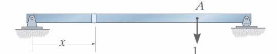
3 External Work Energy Method When a force F undergoes a displacement dx in the same direction i as the force, the work done is du e = F dx If the total displacement is x the work become U e x = F dx 0 1 U e = 2 P The force applied gradually


4 External Work Energy Method If P is already applied to the bar and that another force F`i is now applied The work done by P when the bar undergoes the further deflection ` is then U e ' = P '
5 The work of a moment is defined by the product of the magnitude of the moment M and the angle dθ then du e = M dθ If the total angle of rotation is θ the work become: θ U e 0 = M dθ U e 2 1 = Mθ The moment applied gradually
6 Energy Method Strain Energy Axial Force σ = Eε σ = ε = N A L = NL AE P = N U = 1 P 2 2 N L U i = 2AE N=internal normal force in a truss member caused by the real load L = length of member A = cross-sectional area of a member E = modulus of elasticity of a member
7 Energy Method Strain Energy Bending dθ = U = 1 2 M dx EI Mθ du U i i = L = 0 2 M dx 2EI 2 M dx 2EI


8 Principle of Virtual Work P = Work of Etrnl External Loads u δ Work of Internal Loads Virtual Load 1. = u. dl Real displacement
9 Method of Virtual Work: Trusses External Loading 1. = u. dl 1. = n. NL AE 1 = external virtual unit load acting on the truss joint in the stated t direction of n = internal virtual normal force in a truss member caused by the external virtual unit load = external joint displacement caused by the real load on the truss N = internal normal force in a truss member caused by the real load L = length of member A = cross-sectional area of a member E = modulus of elasticity of a member
10 Method of Virtual Work: Trusses Temperature 1. = n α T L 1 = external virtual unit load acting on the truss joint in the stated direction of n = internal virtual normal force in a truss member caused by the external virtual unit load = external joint displacement caused by the temperature change. α = coefficient of thermal expansion of member T = change in temperature of member L = length of member
11 Method of Virtual Work: Trusses Fabrication Errors and Camber 1. = n L 1 = external virtual unit load acting on the truss joint in the stated direction of n = internal virtual normal force in a truss member caused by the external virtual unit load = external joint displacement caused by fabrication errors L = difference in length of the member from its intended size as caused by a fabrication error.
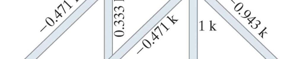
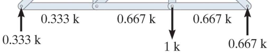
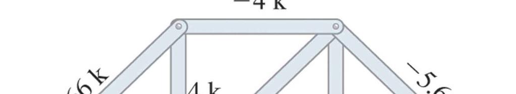
12 Example 1 The cross sectional area of each member of the truss show, is A = 400mm2 & E = 200GPa. a) Determine the vertical displacement of joint C if a 4-kN force is applied to the truss at C
13 Solution 1. = n. NL AE A virtual force of 1 kn is applied at C in the vertical direction
14 Member n (KN) N (KN) L (m) nnl AB AC CB Sum nnl AE AE ( kn 1. = = = 6 2 ( m ) 6 ( kn / m = m = mm ) )
15 Example 2 Text book Example 8-14 Determine vertical displacement at C A = 0.5 in 2 E=29 (10) 3 ksi

16
17
18 Example 3
19
20 Method of Virtual Work: Beam = 1. u. dl M d θ = dx EI L M 1.. = m EI dx 0 1 = t l i t l it l d ti th b i th t t d di ti f 1 = external virtual unit load acting on the beam in the stated direction of m = internal virtual moment in a beam caused by the external virtual unit load = external joint displacement caused by the real load on the truss M = internal moment in a beam caused by the real load L = length of beam I = moment of inertia of cross-sectional E = modulus of elasticity of the beam


21
22 Method of Virtual Work: Beam Similarly the rotation angle at any point on the beam can be determine, a unit couple moment is applied at the point and the corresponding internal moment have to be determine m θ L θ 1( KN. m). θ = 0 m M EI dx
23 Example 4 Determine the displacement at point B of a steel beam E = 200 Gpa, I = 500(10 6 ) mm 4
 6 ( ) 1 ( 1.")
 15(10 )")
 )(10 500(10 ) 200(10 ) (")
24 Solution x dx x dx x x dx M m L 6 6 ) 6 ( ) 1 ( = = = = m EI EI EI dx EI m 0 15 ) 15(10 ) 15( m EI 0.15 ) )(10 500(10 ) 200(10 ) ( ) ( = = =
25 Another Solution Real Load Virtual Load B B = = 200( m ) 500(10 6 )(10 12 ) 7.5
26 Example 5
27
28 Example 6 Determine the Slope θ and displacement at point B of a steel p p p beam E = 200 Gpa, I = 60(10 6 ) mm 4
29 Solution Virtual Load
")

30 Real Load Real Load 3 3 ) 3 ( 1) ( ) 3 ( (0) = = + = = L x x dx dx x dx x dx M m θ d ) 3(5 ) 3( = = + = = EI EI EI EI dx EI m θ θ θ rad ) 60(10 ) 200(10 2 ) ( ) ( 6 6 = = θ B
31 Another Solution Real Load Virtual Load θ = B = 1 = EI EI 112 = (10 9 ) rad
32 Example 7
33
34
35
36 Example 8
37
38
39 Example 9
40
41 Example 9b Determine the horizontal deflection at A
42 Solution Real Load Virtual Load
43 A = = EI EI EI 1250 = m = (10 )
44 Virtual Strain Energy Caused by: Axial Load U = U n nnl AE n = internal virtual axial load caused by the external virtual unit load N = internal normal force in the member caused by the real load L = length of member A = cross-sectional area of the member E = modulus of elasticity of the material
 Caused by: Shear τ")
 L νvν V US = K dx GA")
45 Virtual Strain Energy dy = γ dx γ = τ / G dy = τ / G dx ( ) Caused by: Shear τ = K ( V / A) V dy = K dx GA du = νdy = νk V / A dx S ( ) L νvν V US = K dx GA 0
46 Virtual Strain Energy Caused by: Shear L νv U S = K dx GA 0 ν= internal virtual shear in the member caused by the external virtual unit load V = internal shear in the member caused by the real load G= shear modulus of elasticity for the material A = cross-sectional area of the member K = form factor for the cross-sectional area K=1.2 for rectangular cross sections K=10/9 for circular cross sections K=1.0 for wide-flange and I-beams where A is the area of the web.


47 Virtual Strain Energy γ = cd θ / dx γ = τ / G Tc τ = J τ Caused by: Torsion γ τ T d θ = dx = dx = dx c Gc GJ tt du t = tdθ = dx GJ U t = ttl GJ
48 Virtual Strain Energy Caused by: Torsion U t = ttl GJ t= internal virtual torque caused by the external virtual unit load T= internal shear in the member caused by the real load G= shear modulus of elasticity for the material J = polar moment of inertia of the cross-sectional L = member length


49 Virtual Strain Energy Caused by: Temperature d θ = U temp α T m c L 0 dx mα α T = c m dx
50 Virtual Strain Energy Caused by: Temperature U temp L = 0 m α T c m dx m= internal virtual moment in the beam caused by the external virtual unit load or unit moment α = coefficient of thermal expansion Tm = change in temperature between the mean temperature and the temperature at the top or the bottom of the beam c = mid-depth of the beam
51 Example 10
52
53
54
55 Example 11
56
Module 4 : Deflection of Structures Lecture 4 : Strain Energy Method
 Module 4 : Deflection of Structures Lecture 4 : Strain Energy Method Objectives In this course you will learn the following Deflection by strain energy method. Evaluation of strain energy in member under
14. *14.8 CASTIGLIANO S THEOREM
 *14.8 CASTIGLIANO S THEOREM Consider a body of arbitrary shape subjected to a series of n forces P 1, P 2, P n. Since external work done by forces is equal to internal strain energy stored in body, by
Chapter 2: Deflections of Structures
 Chapter 2: Deflections of Structures Fig. 4.1. (Fig. 2.1.) ASTU, Dept. of C Eng., Prepared by: Melkamu E. Page 1 (2.1) (4.1) (2.2) Fig.4.2 Fig.2.2 ASTU, Dept. of C Eng., Prepared by: Melkamu E. Page 2
Mechanical Properties of Materials
 Mechanical Properties of Materials Strains Material Model Stresses Learning objectives Understand the qualitative and quantitative description of mechanical properties of materials. Learn the logic of
Consider an elastic spring as shown in the Fig.2.4. When the spring is slowly
 .3 Strain Energy Consider an elastic spring as shown in the Fig..4. When the spring is slowly pulled, it deflects by a small amount u 1. When the load is removed from the spring, it goes back to the original
2 marks Questions and Answers
 1. Define the term strain energy. A: Strain Energy of the elastic body is defined as the internal work done by the external load in deforming or straining the body. 2. Define the terms: Resilience and
Mechanical Engineering Ph.D. Preliminary Qualifying Examination Solid Mechanics February 25, 2002
 student personal identification (ID) number on each sheet. Do not write your name on any sheet. #1. A homogeneous, isotropic, linear elastic bar has rectangular cross sectional area A, modulus of elasticity
CHAPTER 5 Statically Determinate Plane Trusses
 CHAPTER 5 Statically Determinate Plane Trusses TYPES OF ROOF TRUSS TYPES OF ROOF TRUSS ROOF TRUSS SETUP ROOF TRUSS SETUP OBJECTIVES To determine the STABILITY and DETERMINACY of plane trusses To analyse
This procedure covers the determination of the moment of inertia about the neutral axis.
 327 Sample Problems Problem 16.1 The moment of inertia about the neutral axis for the T-beam shown is most nearly (A) 36 in 4 (C) 236 in 4 (B) 136 in 4 (D) 736 in 4 This procedure covers the determination
CHAPTER 5 Statically Determinate Plane Trusses TYPES OF ROOF TRUSS
 CHAPTER 5 Statically Determinate Plane Trusses TYPES OF ROOF TRUSS 1 TYPES OF ROOF TRUSS ROOF TRUSS SETUP 2 ROOF TRUSS SETUP OBJECTIVES To determine the STABILITY and DETERMINACY of plane trusses To analyse
Stress Analysis Lecture 3 ME 276 Spring Dr./ Ahmed Mohamed Nagib Elmekawy
 Stress Analysis Lecture 3 ME 276 Spring 2017-2018 Dr./ Ahmed Mohamed Nagib Elmekawy Axial Stress 2 Beam under the action of two tensile forces 3 Beam under the action of two tensile forces 4 Shear Stress
D : SOLID MECHANICS. Q. 1 Q. 9 carry one mark each. Q.1 Find the force (in kn) in the member BH of the truss shown.
 in the member BH of the truss shown.") D : SOLID MECHANICS Q. 1 Q. 9 carry one mark each. Q.1 Find the force (in kn) in the member BH of the truss shown. Q.2 Consider the forces of magnitude F acting on the sides of the regular hexagon having
D : SOLID MECHANICS Q. 1 Q. 9 carry one mark each. Q.1 Find the force (in kn) in the member BH of the truss shown. Q.2 Consider the forces of magnitude F acting on the sides of the regular hexagon having
2. Rigid bar ABC supports a weight of W = 50 kn. Bar ABC is pinned at A and supported at B by rod (1). What is the axial force in rod (1)?
. What is the axial force in rod (1)?") IDE 110 S08 Test 1 Name: 1. Determine the internal axial forces in segments (1), (2) and (3). (a) N 1 = kn (b) N 2 = kn (c) N 3 = kn 2. Rigid bar ABC supports a weight of W = 50 kn. Bar ABC is pinned at
IDE 110 S08 Test 1 Name: 1. Determine the internal axial forces in segments (1), (2) and (3). (a) N 1 = kn (b) N 2 = kn (c) N 3 = kn 2. Rigid bar ABC supports a weight of W = 50 kn. Bar ABC is pinned at
 UNIT III DEFLECTION OF BEAMS 1. What are the methods for finding out the slope and deflection at a section? The important methods used for finding out the slope and deflection at a section in a loaded
Using the finite element method of structural analysis, determine displacements at nodes 1 and 2.
 Question 1 A pin-jointed plane frame, shown in Figure Q1, is fixed to rigid supports at nodes and 4 to prevent their nodal displacements. The frame is loaded at nodes 1 and by a horizontal and a vertical
Chapter 5 Elastic Strain, Deflection, and Stability 1. Elastic Stress-Strain Relationship
 Chapter 5 Elastic Strain, Deflection, and Stability Elastic Stress-Strain Relationship A stress in the x-direction causes a strain in the x-direction by σ x also causes a strain in the y-direction & z-direction
Indeterminate Analysis Force Method 1
 Indeterminate Analysis Force Method 1 The force (flexibility) method expresses the relationships between displacements and forces that exist in a structure. Primary objective of the force method is to
Mechanics of Materials MENG 270 Fall 2003 Exam 3 Time allowed: 90min. Q.1(a) Q.1 (b) Q.2 Q.3 Q.4 Total
 Q.1 (b) Q.2 Q.3 Q.4 Total") Mechanics of Materials MENG 70 Fall 00 Eam Time allowed: 90min Name. Computer No. Q.(a) Q. (b) Q. Q. Q.4 Total Problem No. (a) [5Points] An air vessel is 500 mm average diameter and 0 mm thickness, the
Mechanics of Materials MENG 70 Fall 00 Eam Time allowed: 90min Name. Computer No. Q.(a) Q. (b) Q. Q. Q.4 Total Problem No. (a) [5Points] An air vessel is 500 mm average diameter and 0 mm thickness, the
KINGS COLLEGE OF ENGINEERING DEPARTMENT OF MECHANICAL ENGINEERING QUESTION BANK. Subject code/name: ME2254/STRENGTH OF MATERIALS Year/Sem:II / IV
 KINGS COLLEGE OF ENGINEERING DEPARTMENT OF MECHANICAL ENGINEERING QUESTION BANK Subject code/name: ME2254/STRENGTH OF MATERIALS Year/Sem:II / IV UNIT I STRESS, STRAIN DEFORMATION OF SOLIDS PART A (2 MARKS)
2. Determine the deflection at C of the beam given in fig below. Use principal of virtual work. W L/2 B A L C
 CE-1259, Strength of Materials UNIT I STRESS, STRAIN DEFORMATION OF SOLIDS Part -A 1. Define strain energy density. 2. State Maxwell s reciprocal theorem. 3. Define proof resilience. 4. State Castigliano
SSC-JE MAINS ONLINE TEST SERIES / CIVIL ENGINEERING SOM + TOS
 SSC-JE MAINS ONLINE TEST SERIES / CIVIL ENGINEERING SOM + TOS Time Allowed:2 Hours Maximum Marks: 300 Attention: 1. Paper consists of Part A (Civil & Structural) Part B (Electrical) and Part C (Mechanical)
Symmetric Bending of Beams
 Symmetric Bending of Beams beam is any long structural member on which loads act perpendicular to the longitudinal axis. Learning objectives Understand the theory, its limitations and its applications
Method of Virtual Work Frame Deflection Example Steven Vukazich San Jose State University
 Method of Virtual Work Frame Deflection xample Steven Vukazich San Jose State University Frame Deflection xample 9 k k D 4 ft θ " # The statically determinate frame from our previous internal force diagram
INTRODUCTION TO STRAIN
 SIMPLE STRAIN INTRODUCTION TO STRAIN In general terms, Strain is a geometric quantity that measures the deformation of a body. There are two types of strain: normal strain: characterizes dimensional changes,
JUT!SI I I I TO BE RETURNED AT THE END OF EXAMINATION. THIS PAPER MUST NOT BE REMOVED FROM THE EXAM CENTRE. SURNAME: FIRST NAME: STUDENT NUMBER:
 JUT!SI I I I TO BE RETURNED AT THE END OF EXAMINATION. THIS PAPER MUST NOT BE REMOVED FROM THE EXAM CENTRE. SURNAME: FIRST NAME: STUDENT NUMBER: COURSE: Tutor's name: Tutorial class day & time: SPRING
Chapter 11. Displacement Method of Analysis Slope Deflection Method
 Chapter 11 Displacement ethod of Analysis Slope Deflection ethod Displacement ethod of Analysis Two main methods of analyzing indeterminate structure Force method The method of consistent deformations
D : SOLID MECHANICS. Q. 1 Q. 9 carry one mark each.
 GTE 2016 Q. 1 Q. 9 carry one mark each. D : SOLID MECHNICS Q.1 single degree of freedom vibrating system has mass of 5 kg, stiffness of 500 N/m and damping coefficient of 100 N-s/m. To make the system
Interstate 35W Bridge Collapse in Minnesota (2007) AP Photo/Pioneer Press, Brandi Jade Thomas
 AP Photo/Pioneer Press, Brandi Jade Thomas") 7 Interstate 35W Bridge Collapse in Minnesota (2007) AP Photo/Pioneer Press, Brandi Jade Thomas Deflections of Trusses, Beams, and Frames: Work Energy Methods 7.1 Work 7.2 Principle of Virtual Work 7.3
7 Interstate 35W Bridge Collapse in Minnesota (2007) AP Photo/Pioneer Press, Brandi Jade Thomas Deflections of Trusses, Beams, and Frames: Work Energy Methods 7.1 Work 7.2 Principle of Virtual Work 7.3
Question 1. Ignore bottom surface. Solution: Design variables: X = (R, H) Objective function: maximize volume, πr 2 H OR Minimize, f(x) = πr 2 H
 Objective function: maximize volume, πr 2 H OR Minimize, f(x) = πr 2 H") Question 1 (Problem 2.3 of rora s Introduction to Optimum Design): Design a beer mug, shown in fig, to hold as much beer as possible. The height and radius of the mug should be not more than 20 cm. The
Question 1 (Problem 2.3 of rora s Introduction to Optimum Design): Design a beer mug, shown in fig, to hold as much beer as possible. The height and radius of the mug should be not more than 20 cm. The
FIXED BEAMS IN BENDING
 FIXED BEAMS IN BENDING INTRODUCTION Fixed or built-in beams are commonly used in building construction because they possess high rigidity in comparison to simply supported beams. When a simply supported
5. What is the moment of inertia about the x - x axis of the rectangular beam shown?
 1 of 5 Continuing Education Course #274 What Every Engineer Should Know About Structures Part D - Bending Strength Of Materials NOTE: The following question was revised on 15 August 2018 1. The moment
k 21 k 22 k 23 k 24 k 31 k 32 k 33 k 34 k 41 k 42 k 43 k 44
 CE 6 ab Beam Analysis by the Direct Stiffness Method Beam Element Stiffness Matrix in ocal Coordinates Consider an inclined bending member of moment of inertia I and modulus of elasticity E subjected shear
ME 323 Examination #2 April 11, 2018
 ME 2 Eamination #2 April, 2 PROBLEM NO. 25 points ma. A thin-walled pressure vessel is fabricated b welding together two, open-ended stainless-steel vessels along a 6 weld line. The welded vessel has an
Mechanics of Materials II. Chapter III. A review of the fundamental formulation of stress, strain, and deflection
 Mechanics of Materials II Chapter III A review of the fundamental formulation of stress, strain, and deflection Outline Introduction Assumtions and limitations Axial loading Torsion of circular shafts
UNIT-I STRESS, STRAIN. 1. A Member A B C D is subjected to loading as shown in fig determine the total elongation. Take E= 2 x10 5 N/mm 2
 UNIT-I STRESS, STRAIN 1. A Member A B C D is subjected to loading as shown in fig determine the total elongation. Take E= 2 x10 5 N/mm 2 Young s modulus E= 2 x10 5 N/mm 2 Area1=900mm 2 Area2=400mm 2 Area3=625mm
Stress Analysis Lecture 4 ME 276 Spring Dr./ Ahmed Mohamed Nagib Elmekawy
 Stress Analysis Lecture 4 ME 76 Spring 017-018 Dr./ Ahmed Mohamed Nagib Elmekawy Shear and Moment Diagrams Beam Sign Convention The positive directions are as follows: The internal shear force causes a
TORSION INCLUDING WARPING OF OPEN SECTIONS (I, C, Z, T AND L SHAPES)
") Page1 TORSION INCLUDING WARPING OF OPEN SECTIONS (I, C, Z, T AND L SHAPES) Restrained warping for the torsion of thin-wall open sections is not included in most commonly used frame analysis programs. Almost
Page1 TORSION INCLUDING WARPING OF OPEN SECTIONS (I, C, Z, T AND L SHAPES) Restrained warping for the torsion of thin-wall open sections is not included in most commonly used frame analysis programs. Almost
BEAM DEFLECTION THE ELASTIC CURVE
 BEAM DEFLECTION Samantha Ramirez THE ELASTIC CURVE The deflection diagram of the longitudinal axis that passes through the centroid of each cross-sectional area of a beam. Supports that apply a moment
QUESTION BANK DEPARTMENT: CIVIL SEMESTER: III SUBJECT CODE: CE2201 SUBJECT NAME: MECHANICS OF SOLIDS UNIT 1- STRESS AND STRAIN PART A
 DEPARTMENT: CIVIL SUBJECT CODE: CE2201 QUESTION BANK SEMESTER: III SUBJECT NAME: MECHANICS OF SOLIDS UNIT 1- STRESS AND STRAIN PART A (2 Marks) 1. Define longitudinal strain and lateral strain. 2. State
BEAMS AND PLATES ANALYSIS
 BEAMS AND PLATES ANALYSIS Automotive body structure can be divided into two types: i. Frameworks constructed of beams ii. Panels Classical beam versus typical modern vehicle beam sections Assumptions:
Final Exam Ship Structures Page 1 MEMORIAL UNIVERSITY OF NEWFOUNDLAND. Engineering Ship Structures
 Final Exam - 53 - Ship Structures - 16 Page 1 MEMORIA UNIVERSITY OF NEWFOUNDAND Faculty of Engineering and Applied Science Engineering 53 - Ship Structures FINA EXAMINATION SONS Date: Wednesday April 13,
Method of Consistent Deformation
 Method of onsistent eformation Structural nalysis y R.. Hibbeler Theory of Structures-II M Shahid Mehmood epartment of ivil Engineering Swedish ollege of Engineering and Technology, Wah antt FRMES Method
M. Vable Mechanics of Materials: Chapter 5. Torsion of Shafts
 Torsion of Shafts Shafts are structural members with length significantly greater than the largest cross-sectional dimension used in transmitting torque from one plane to another. Learning objectives Understand
Module 3. Analysis of Statically Indeterminate Structures by the Displacement Method
 odule 3 Analysis of Statically Indeterminate Structures by the Displacement ethod Lesson 16 The Slope-Deflection ethod: rames Without Sidesway Instructional Objectives After reading this chapter the student
Name :. Roll No. :... Invigilator s Signature :.. CS/B.TECH (CE-NEW)/SEM-3/CE-301/ SOLID MECHANICS
/SEM-3/CE-301/ SOLID MECHANICS") Name :. Roll No. :..... Invigilator s Signature :.. 2011 SOLID MECHANICS Time Allotted : 3 Hours Full Marks : 70 The figures in the margin indicate full marks. Candidates are required to give their answers
Name :. Roll No. :..... Invigilator s Signature :.. 2011 SOLID MECHANICS Time Allotted : 3 Hours Full Marks : 70 The figures in the margin indicate full marks. Candidates are required to give their answers
Comb resonator design (2)
") Lecture 6: Comb resonator design () -Intro Intro. to Mechanics of Materials School of Electrical l Engineering i and Computer Science, Seoul National University Nano/Micro Systems & Controls Laboratory
Lecture 6: Comb resonator design () -Intro Intro. to Mechanics of Materials School of Electrical l Engineering i and Computer Science, Seoul National University Nano/Micro Systems & Controls Laboratory
Torsion of Shafts Learning objectives
 Torsion of Shafts Shafts are structural members with length significantly greater than the largest cross-sectional dimension used in transmitting torque from one plane to another. Learning objectives Understand
and F NAME: ME rd Sample Final Exam PROBLEM 1 (25 points) Prob. 1 questions are all or nothing. PROBLEM 1A. (5 points)
 Prob. 1 questions are all or nothing. PROBLEM 1A. (5 points)") ME 270 3 rd Sample inal Exam PROBLEM 1 (25 points) Prob. 1 questions are all or nothing. PROBLEM 1A. (5 points) IND: In your own words, please state Newton s Laws: 1 st Law = 2 nd Law = 3 rd Law = PROBLEM
ME 270 3 rd Sample inal Exam PROBLEM 1 (25 points) Prob. 1 questions are all or nothing. PROBLEM 1A. (5 points) IND: In your own words, please state Newton s Laws: 1 st Law = 2 nd Law = 3 rd Law = PROBLEM
2012 MECHANICS OF SOLIDS
 R10 SET - 1 II B.Tech II Semester, Regular Examinations, April 2012 MECHANICS OF SOLIDS (Com. to ME, AME, MM) Time: 3 hours Max. Marks: 75 Answer any FIVE Questions All Questions carry Equal Marks ~~~~~~~~~~~~~~~~~~~~~~
Level 7 Postgraduate Diploma in Engineering Computational mechanics using finite element method
 9210-203 Level 7 Postgraduate Diploma in Engineering Computational mechanics using finite element method You should have the following for this examination one answer book No additional data is attached
The University of Melbourne Engineering Mechanics
 The University of Melbourne 436-291 Engineering Mechanics Tutorial Four Poisson s Ratio and Axial Loading Part A (Introductory) 1. (Problem 9-22 from Hibbeler - Statics and Mechanics of Materials) A short
Finite Element Analysis Prof. Dr. B. N. Rao Department of Civil Engineering Indian Institute of Technology, Madras. Module - 01 Lecture - 13
 Finite Element Analysis Prof. Dr. B. N. Rao Department of Civil Engineering Indian Institute of Technology, Madras (Refer Slide Time: 00:25) Module - 01 Lecture - 13 In the last class, we have seen how
Strength of Materials II (Mechanics of Materials) (SI Units) Dr. Ashraf Alfeehan
 (SI Units) Dr. Ashraf Alfeehan") Strength of Materials II (Mechanics of Materials) (SI Units) Dr. Ashraf Alfeehan 2017-2018 Mechanics of Material II Text Books Mechanics of Materials, 10th edition (SI version), by: R. C. Hibbeler, 2017
Strength of Materials II (Mechanics of Materials) (SI Units) Dr. Ashraf Alfeehan 2017-2018 Mechanics of Material II Text Books Mechanics of Materials, 10th edition (SI version), by: R. C. Hibbeler, 2017
STATICALLY INDETERMINATE STRUCTURES
 STATICALLY INDETERMINATE STRUCTURES INTRODUCTION Generally the trusses are supported on (i) a hinged support and (ii) a roller support. The reaction components of a hinged support are two (in horizontal
STRUCTURAL SURFACES & FLOOR GRILLAGES
 STRUCTURAL SURFACES & FLOOR GRILLAGES INTRODUCTION Integral car bodies are 3D structures largely composed of approximately subassemblies- SSS Planar structural subassemblies can be grouped into two categories
Mechanics of Materials Primer
 Mechanics of Materials rimer Notation: A = area (net = with holes, bearing = in contact, etc...) b = total width of material at a horizontal section d = diameter of a hole D = symbol for diameter E = modulus
UNIVERSITY OF SASKATCHEWAN ME MECHANICS OF MATERIALS I FINAL EXAM DECEMBER 13, 2008 Professor A. Dolovich
 UNIVERSITY OF SASKATCHEWAN ME 313.3 MECHANICS OF MATERIALS I FINAL EXAM DECEMBER 13, 2008 Professor A. Dolovich A CLOSED BOOK EXAMINATION TIME: 3 HOURS For Marker s Use Only LAST NAME (printed): FIRST
Module 2. Analysis of Statically Indeterminate Structures by the Matrix Force Method
 Module 2 Analysis of Statically Indeterminate Structures by the Matrix Force Method Lesson 11 The Force Method of Analysis: Frames Instructional Objectives After reading this chapter the student will be
1-1 Locate the centroid of the plane area shown. 1-2 Determine the location of centroid of the composite area shown.
 Chapter 1 Review of Mechanics of Materials 1-1 Locate the centroid of the plane area shown 650 mm 1000 mm 650 x 1- Determine the location of centroid of the composite area shown. 00 150 mm radius 00 mm
Review of Strain Energy Methods and Introduction to Stiffness Matrix Methods of Structural Analysis
 uke University epartment of Civil and Environmental Engineering CEE 42L. Matrix Structural Analysis Henri P. Gavin Fall, 22 Review of Strain Energy Methods and Introduction to Stiffness Matrix Methods
Outline. Organization. Stresses in Beams
 Stresses in Beams B the end of this lesson, ou should be able to: Calculate the maimum stress in a beam undergoing a bending moment 1 Outline Curvature Normal Strain Normal Stress Neutral is Moment of
8-5 Conjugate-Beam method. 8-5 Conjugate-Beam method. 8-5 Conjugate-Beam method. 8-5 Conjugate-Beam method
 The basis for the method comes from the similarity of eqn.1 &. to eqn 8. & 8. To show this similarity, we can write these eqn as shown dv dx w d θ M dx d M w dx d v M dx Here the shear V compares with
R13. II B. Tech I Semester Regular Examinations, Jan MECHANICS OF SOLIDS (Com. to ME, AME, AE, MTE) PART-A
 PART-A") SET - 1 II B. Tech I Semester Regular Examinations, Jan - 2015 MECHANICS OF SOLIDS (Com. to ME, AME, AE, MTE) Time: 3 hours Max. Marks: 70 Note: 1. Question Paper consists of two parts (Part-A and Part-B)
SET - 1 II B. Tech I Semester Regular Examinations, Jan - 2015 MECHANICS OF SOLIDS (Com. to ME, AME, AE, MTE) Time: 3 hours Max. Marks: 70 Note: 1. Question Paper consists of two parts (Part-A and Part-B)
PES Institute of Technology
 PES Institute of Technology Bangalore south campus, Bangalore-5460100 Department of Mechanical Engineering Faculty name : Madhu M Date: 29/06/2012 SEM : 3 rd A SEC Subject : MECHANICS OF MATERIALS Subject
QUESTION BANK SEMESTER: III SUBJECT NAME: MECHANICS OF SOLIDS
 QUESTION BANK SEMESTER: III SUBJECT NAME: MECHANICS OF SOLIDS UNIT 1- STRESS AND STRAIN PART A (2 Marks) 1. Define longitudinal strain and lateral strain. 2. State Hooke s law. 3. Define modular ratio,
Module 3. Analysis of Statically Indeterminate Structures by the Displacement Method
 odule 3 Analysis of Statically Indeterminate Structures by the Displacement ethod Lesson 21 The oment- Distribution ethod: rames with Sidesway Instructional Objectives After reading this chapter the student
ME Final Exam. PROBLEM NO. 4 Part A (2 points max.) M (x) y. z (neutral axis) beam cross-sec+on. 20 kip ft. 0.2 ft. 10 ft. 0.1 ft.
 M (x) y. z (neutral axis) beam cross-sec+on. 20 kip ft. 0.2 ft. 10 ft. 0.1 ft.") ME 323 - Final Exam Name December 15, 2015 Instructor (circle) PROEM NO. 4 Part A (2 points max.) Krousgrill 11:30AM-12:20PM Ghosh 2:30-3:20PM Gonzalez 12:30-1:20PM Zhao 4:30-5:20PM M (x) y 20 kip ft 0.2
ME 323 - Final Exam Name December 15, 2015 Instructor (circle) PROEM NO. 4 Part A (2 points max.) Krousgrill 11:30AM-12:20PM Ghosh 2:30-3:20PM Gonzalez 12:30-1:20PM Zhao 4:30-5:20PM M (x) y 20 kip ft 0.2
Name (Print) ME Mechanics of Materials Exam # 1 Date: October 5, 2016 Time: 8:00 10:00 PM
 ME Mechanics of Materials Exam # 1 Date: October 5, 2016 Time: 8:00 10:00 PM") Name (Print) (Last) (First) Instructions: ME 323 - Mechanics of Materials Exam # 1 Date: October 5, 2016 Time: 8:00 10:00 PM Circle your lecturer s name and your class meeting time. Gonzalez Krousgrill
Name (Print) (Last) (First) Instructions: ME 323 - Mechanics of Materials Exam # 1 Date: October 5, 2016 Time: 8:00 10:00 PM Circle your lecturer s name and your class meeting time. Gonzalez Krousgrill
Review Lecture. AE1108-II: Aerospace Mechanics of Materials. Dr. Calvin Rans Dr. Sofia Teixeira De Freitas
 Review Lecture AE1108-II: Aerospace Mechanics of Materials Dr. Calvin Rans Dr. Sofia Teixeira De Freitas Aerospace Structures & Materials Faculty of Aerospace Engineering Analysis of an Engineering System
ME C85/CE C30 Fall, Introduction to Solid Mechanics ME C85/CE C30. Final Exam. Fall, 2013
 Introduction to Solid Mechanics ME C85/CE C30 Fall, 2013 1. Leave an empty seat between you and the person (people) next to you. Unfortunately, there have been reports of cheating on the midterms, so we
DESIGN OF BEAMS AND SHAFTS
 DESIGN OF EAMS AND SHAFTS! asis for eam Design! Stress Variations Throughout a Prismatic eam! Design of pristmatic beams! Steel beams! Wooden beams! Design of Shaft! ombined bending! Torsion 1 asis for
BE Semester- I ( ) Question Bank (MECHANICS OF SOLIDS)
 Question Bank (MECHANICS OF SOLIDS)") BE Semester- I ( ) Question Bank (MECHANICS OF SOLIDS) All questions carry equal marks(10 marks) Q.1 (a) Write the SI units of following quantities and also mention whether it is scalar or vector: (i)
BE Semester- I ( ) Question Bank (MECHANICS OF SOLIDS) All questions carry equal marks(10 marks) Q.1 (a) Write the SI units of following quantities and also mention whether it is scalar or vector: (i)
MECHANICS OF MATERIALS
 Third E CHAPTER 2 Stress MECHANICS OF MATERIALS Ferdinand P. Beer E. Russell Johnston, Jr. John T. DeWolf Lecture Notes: J. Walt Oler Texas Tech University and Strain Axial Loading Contents Stress & Strain:
PDDC 1 st Semester Civil Engineering Department Assignments of Mechanics of Solids [ ] Introduction, Fundamentals of Statics
![PDDC 1 st Semester Civil Engineering Department Assignments of Mechanics of Solids [ ] Introduction, Fundamentals of Statics](/thumbs/92/109382806.jpg "PDDC 1 st Semester Civil Engineering Department Assignments of Mechanics of Solids [ ] Introduction, Fundamentals of Statics") Page1 PDDC 1 st Semester Civil Engineering Department Assignments of Mechanics of Solids [2910601] Introduction, Fundamentals of Statics 1. Differentiate between Scalar and Vector quantity. Write S.I.
Page1 PDDC 1 st Semester Civil Engineering Department Assignments of Mechanics of Solids [2910601] Introduction, Fundamentals of Statics 1. Differentiate between Scalar and Vector quantity. Write S.I.
= 50 ksi. The maximum beam deflection Δ max is not = R B. = 30 kips. Notes for Strength of Materials, ET 200
 Notes for Strength of Materials, ET 00 Steel Six Easy Steps Steel beam design is about selecting the lightest steel beam that will support the load without exceeding the bending strength or shear strength
Chapter 6: Cross-Sectional Properties of Structural Members
 Chapter 6: Cross-Sectional Properties of Structural Members Introduction Beam design requires the knowledge of the following. Material strengths (allowable stresses) Critical shear and moment values Cross
[7] Torsion. [7.1] Torsion. [7.2] Statically Indeterminate Torsion. [7] Torsion Page 1 of 21
![[7] Torsion. [7.1] Torsion. [7.2] Statically Indeterminate Torsion. [7] Torsion Page 1 of 21](/thumbs/88/115835122.jpg "[7] Torsion. [7.1] Torsion. [7.2] Statically Indeterminate Torsion. [7] Torsion Page 1 of 21") [7] Torsion Page 1 of 21 [7] Torsion [7.1] Torsion [7.2] Statically Indeterminate Torsion [7] Torsion Page 2 of 21 [7.1] Torsion SHEAR STRAIN DUE TO TORSION 1) A shaft with a circular cross section is
[7] Torsion Page 1 of 21 [7] Torsion [7.1] Torsion [7.2] Statically Indeterminate Torsion [7] Torsion Page 2 of 21 [7.1] Torsion SHEAR STRAIN DUE TO TORSION 1) A shaft with a circular cross section is
Example 3.7 Consider the undeformed configuration of a solid as shown in Figure 3.60.
 162 3. The linear 3-D elasticity mathematical model The 3-D elasticity model is of great importance, since it is our highest order hierarchical model assuming linear elastic behavior. Therefore, it provides
Theory of Structures
 SAMPLE STUDY MATERIAL Postal Correspondence Course GATE, IES & PSUs Civil Engineering Theory of Structures C O N T E N T 1. ARCES... 3-14. ROLLING LOADS AND INFLUENCE LINES. 15-9 3. DETERMINACY AND INDETERMINACY..
[5] Stress and Strain
![[5] Stress and Strain](/thumbs/95/123344550.jpg "[5] Stress and Strain") [5] Stress and Strain Page 1 of 34 [5] Stress and Strain [5.1] Internal Stress of Solids [5.2] Design of Simple Connections (will not be covered in class) [5.3] Deformation and Strain [5.4] Hooke s Law
[5] Stress and Strain Page 1 of 34 [5] Stress and Strain [5.1] Internal Stress of Solids [5.2] Design of Simple Connections (will not be covered in class) [5.3] Deformation and Strain [5.4] Hooke s Law
UNIT 1 STRESS STRAIN AND DEFORMATION OF SOLIDS, STATES OF STRESS 1. Define stress. When an external force acts on a body, it undergoes deformation.
 UNIT 1 STRESS STRAIN AND DEFORMATION OF SOLIDS, STATES OF STRESS 1. Define stress. When an external force acts on a body, it undergoes deformation. At the same time the body resists deformation. The magnitude
The science of elasticity
 The science of elasticity In 1676 Hooke realized that 1.Every kind of solid changes shape when a mechanical force acts on it. 2.It is this change of shape which enables the solid to supply the reaction
Shafts: Torsion of Circular Shafts Reading: Crandall, Dahl and Lardner 6.2, 6.3
 M9 Shafts: Torsion of Circular Shafts Reading: Crandall, Dahl and Lardner 6., 6.3 A shaft is a structural member which is long and slender and subject to a torque (moment) acting about its long axis. We
NAME: Given Formulae: Law of Cosines: Law of Sines:
 NME: Given Formulae: Law of Cosines: EXM 3 PST PROBLEMS (LESSONS 21 TO 28) 100 points Thursday, November 16, 2017, 7pm to 9:30, Room 200 You are allowed to use a calculator and drawing equipment, only.
IDE 110 Mechanics of Materials Spring 2006 Final Examination FOR GRADING ONLY
 Spring 2006 Final Examination STUDENT S NAME (please print) STUDENT S SIGNATURE STUDENT NUMBER IDE 110 CLASS SECTION INSTRUCTOR S NAME Do not turn this page until instructed to start. Write your name on
ME325 EXAM I (Sample)
") ME35 EXAM I (Sample) NAME: NOTE: COSED BOOK, COSED NOTES. ONY A SINGE 8.5x" ORMUA SHEET IS AOWED. ADDITIONA INORMATION IS AVAIABE ON THE AST PAGE O THIS EXAM. DO YOUR WORK ON THE EXAM ONY (NO SCRATCH PAPER
ME35 EXAM I (Sample) NAME: NOTE: COSED BOOK, COSED NOTES. ONY A SINGE 8.5x" ORMUA SHEET IS AOWED. ADDITIONA INORMATION IS AVAIABE ON THE AST PAGE O THIS EXAM. DO YOUR WORK ON THE EXAM ONY (NO SCRATCH PAPER
Advanced Structural Analysis EGF Section Properties and Bending
 Advanced Structural Analysis EGF316 3. Section Properties and Bending 3.1 Loads in beams When we analyse beams, we need to consider various types of loads acting on them, for example, axial forces, shear
MECE 3321 MECHANICS OF SOLIDS CHAPTER 3
 MECE 3321 MECHANICS OF SOLIDS CHAPTER 3 Samantha Ramirez TENSION AND COMPRESSION TESTS Tension and compression tests are used primarily to determine the relationship between σ avg and ε avg in any material.
UNIT-I Introduction & Plane Stress and Plane Strain Analysis
 SIDDHARTH INSTITUTE OF ENGINEERING & TECHNOLOGY:: PUTTUR (AUTONOMOUS) Siddharth Nagar, Narayanavanam Road 517583 QUESTION BANK (DESCRIPTIVE) Subject with Code : Advanced Solid Mechanics (18CE1002) Year
SECTION A. 8 kn/m. C 3 m 3m
 SECTION Question 1 150 m 40 kn 5 kn 8 kn/m C 3 m 3m D 50 ll dimensions in mm 15 15 Figure Q1(a) Figure Q1(b) The horizontal beam CD shown in Figure Q1(a) has a uniform cross-section as shown in Figure
ME 323 FINAL EXAM FALL SEMESTER :00 PM 9:00 PM Dec. 16, 2010
 ME 33 FINA EXAM FA SEMESTER 1 7: PM 9: PM Dec. 16, 1 Instructions 1. Begin each problem in the space provided on the eamination sheets. If additional space is required, use the paper provided. Work on
Comb Resonator Design (2)
") Lecture 6: Comb Resonator Design () -Intro. to Mechanics of Materials Sh School of felectrical ti lengineering i and dcomputer Science, Si Seoul National University Nano/Micro Systems & Controls Laboratory
Lecture 6: Comb Resonator Design () -Intro. to Mechanics of Materials Sh School of felectrical ti lengineering i and dcomputer Science, Si Seoul National University Nano/Micro Systems & Controls Laboratory
Chapter 8 Supplement: Deflection in Beams Double Integration Method
 Chapter 8 Supplement: Deflection in Beams Double Integration Method 8.5 Beam Deflection Double Integration Method In this supplement, we describe the methods for determining the equation of the deflection
Solution: The strain in the bar is: ANS: E =6.37 GPa Poison s ration for the material is:
 Problem 10.4 A prismatic bar with length L 6m and a circular cross section with diameter D 0.0 m is subjected to 0-kN compressive forces at its ends. The length and diameter of the deformed bar are measured
EMA 3702 Mechanics & Materials Science (Mechanics of Materials) Chapter 3 Torsion
 Chapter 3 Torsion") EMA 3702 Mechanics & Materials Science (Mechanics of Materials) Chapter 3 Torsion Introduction Stress and strain in components subjected to torque T Circular Cross-section shape Material Shaft design Non-circular
EMA 3702 Mechanics & Materials Science (Mechanics of Materials) Chapter 3 Torsion Introduction Stress and strain in components subjected to torque T Circular Cross-section shape Material Shaft design Non-circular
3 2 6 Solve the initial value problem u ( t) 3. a- If A has eigenvalues λ =, λ = 1 and corresponding eigenvectors 1
 3. a- If A has eigenvalues λ =, λ = 1 and corresponding eigenvectors 1") Math Problem a- If A has eigenvalues λ =, λ = 1 and corresponding eigenvectors 1 3 6 Solve the initial value problem u ( t) = Au( t) with u (0) =. 3 1 u 1 =, u 1 3 = b- True or false and why 1. if A is
Math Problem a- If A has eigenvalues λ =, λ = 1 and corresponding eigenvectors 1 3 6 Solve the initial value problem u ( t) = Au( t) with u (0) =. 3 1 u 1 =, u 1 3 = b- True or false and why 1. if A is
MECHANICS OF MATERIALS
 STATICS AND MECHANICS OF MATERIALS Ferdinand P. Beer E. Russell Johnston, Jr, John T. DeWolf David E Mazurek \Cawect Mc / iur/» Craw SugomcT Hilt Introduction 1 1.1 What is Mechanics? 2 1.2 Fundamental
Chapter 4-b Axially Loaded Members
 CIVL 222 STRENGTH OF MATERIALS Chapter 4-b Axially Loaded Members AXIAL LOADED MEMBERS Today s Objectives: Students will be able to: a) Determine the elastic deformation of axially loaded member b) Apply
ε t increases from the compressioncontrolled Figure 9.15: Adjusted interaction diagram
 CHAPTER NINE COLUMNS 4 b. The modified axial strength in compression is reduced to account for accidental eccentricity. The magnitude of axial force evaluated in step (a) is multiplied by 0.80 in case
Chapter 5 Structural Elements: The truss & beam elements
 Institute of Structural Engineering Page 1 Chapter 5 Structural Elements: The truss & beam elements Institute of Structural Engineering Page 2 Chapter Goals Learn how to formulate the Finite Element Equations