Comb Resonator Design (2)
|
|
|
- Charla Taylor
- 5 years ago
- Views:
Transcription
1 Lecture 6: Comb Resonator Design () -Intro. to Mechanics of Materials Sh School of felectrical ti lengineering i and dcomputer Science, Si Seoul National University Nano/Micro Systems & Controls Laboratory dicho@snu.ac.kr URL:
2 Stress Normal Stress: force applied to surface σ F / A measured in N/m or Pa, compressive or tensile Shear Stress: force applied parallel to surface τ F / A measured in N/m or Pa Young s Modulus: E σ / ε Hooke s Law: K F/ Δ l EA/ l usage and possession is in violation of copyright laws


3 Strain Strain: ratio of deformation to length γ Δll / l Shear Modulus G τ / γ Relation among: G, E, and ν G E (1 + +ν ) usage and possession is in violation of copyright laws

4 Poisson s Ratio Tensile stress in direction results in compressive stress in y and z direction (object becomes longer and thinner) Poisson s Ratio: ε ε ν y ε z ε transverse strain longitudinal strain Metals : ν 0. Rubbers : ν Cork : ν 0 usage and possession is in violation of copyright laws 4


5 State of Stress The combination of forces generated by the stresses must satisfy the conditions for equilibrium: F F F y z y z 0 M M M Consider the moments about the z ais: 0 ( τ ) ( τ ) M 0 ΔA a ΔA a z y y τ τ, τ τ and τ τ y y yz zy yz zy Only 6 components of stress are required to define the complete state t of stress. usage and possession is in violation of copyright laws 5


6 Ductile Materials Stress and Strain Diagram usage and possession is in violation of copyright laws 6
 Brittle Materials")


7 Stress and Strain Diagram (cont d) Brittle Materials Stress-strain diagram for a typical brittle material usage and possession is in violation of copyright laws 7

8 Deformations Under Aial Loading From Hooke s Law: σ P σ Eε ε E AE From the definition of strain: ε δ L Equating and solving for the deformation: PL δ AE With variations in loading, cross-section or material properties: PL i i δ A E i i i usage and possession is in violation of copyright laws 8
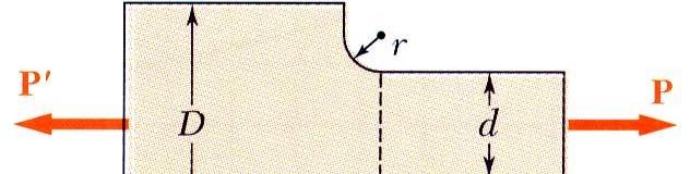
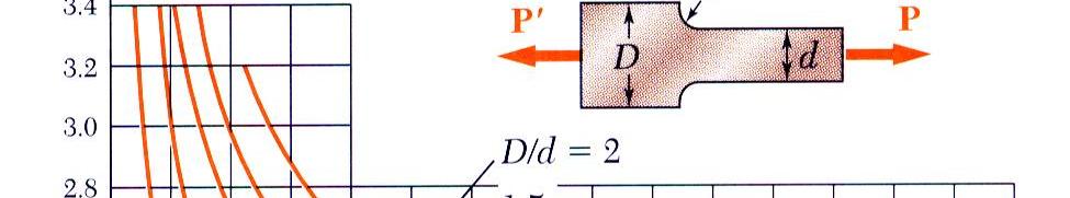
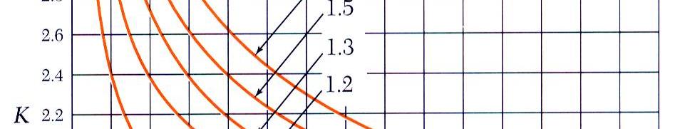
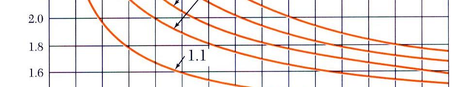

9 Stress Concentration: Fillet σ ma K σ σ ave usage and possession is in violation of copyright laws 9


10 Symmetric Member in Pure Bending Pure Bending: Prismatic members subjected to equal and opposite couples acting in the same longitudinal plane Internal forces in any cross section are equivalent to a couple. The moment of the couple is the section bending moment F y σ da 0 M zσ da 0 M y σ da M z usage and possession is in violation of copyright laws 10

 c c or ρ ρ εm y ε m c usage and possession is in")
11 Strain Due to Bending Consider a beam segment of length L. After deformation, the length of the neutral surface remains L. At other sections, ( ρ y) θ ( ) L δ L L ρ y θ ρθ yθ ε ε ε m δ yθ ρθ y L ρ (strain varies linearly) c c or ρ ρ εm y ε m c usage and possession is in violation of copyright laws 11
 c For")


12 For a linearly elastic material, Stress Due to Bending y σ Eε Eεm c y σ m (stress varies linearly) c For static equilibrium, y F 0 σ da σ m da c σ m 0 yda c First moment with respect to neutral plane is zero. Therefore, the neutral surface must pass through the section centroid. usage and possession is in violation of copyright laws 1
13 Stress Due to Bending (cont d) For static equilibrium, Bending Momentum M t M df( h) h ( σ ( h) da) h A t w t h h σ ma σ ma M ( σ ma da) h h da I t t t w t w t h ( ) ( ) h ( ) Mt sma EI t where σ ma : magnitude of stress I : moment of inertia of the cross-section h : height of a beam t : thickness of a beam s ma : maimum longitudinal strain usage and possession is in violation of copyright laws 1

14 Deformations in a Transverse Cross Section Deformation due to bending moment M is quantified by the curvature of the neutral surface 1 ε σ 1 ρ c Ec Ec I m m Mc M EI Although cross sectional planes remain planar when subjected to bending moments, in-plane deformations are nonzero, ν y ν y εy νε ε z νε ρ ρ usage and possession is in violation of copyright laws 14

15 Bending of Beams Reaction Forces and Moments - For equilibrium F 0 F F 0, therefore F F R R M0 0 MR + FL 0, therefore MR FL usage and possession is in violation of copyright laws 15
16 Bending of Beams (cont d) Shear Forces and Moments (at any point in the beam) At every point along the beam equilibrium requires that, F 0 and M 0 F 0 F + V( ) 0 V F M 0 M( ) + F( L ) 0 M( ) F( L ) L usage and possession is in violation of copyright laws 16
 M ( V + dv ) d qd 0 ( M + dm) M dm V (neglecting q( d ) terms).")
17 Bending of Beams Differential Element Equilibrium of a fully loaded differential element: For equilibrium, F 0 and M 0 ( V + dv ) V dv F 0 qd + ( V + dv) V 0 q - d d d M 0 ( M + dm ) M ( V + dv ) d qd 0 ( M + dm) M dm V (neglecting q( d ) terms). d d usage and possession is in violation of copyright laws 17
18 Bending of Beams Differential Element (cont d) Approimation for radius of curvature: An increment of beam length d is related to ds via d cos( θ), for small θ d ds ds The slope of the beam at any point is given by dw d tan( θ), for small θ θ dw d For a given radius of curvature, ds is related to dθ via 1 ds d, so for small d θ ρ θ θ d w d ρ d usage and possession is in violation of copyright laws 18
19 Bending of Beams Differential Element (cont d) Basic Differential Equations for Beam Bending: d w 1 For small θ d ρ Now that we have a relationship between w( ) and ρ. We can epress the moment and shear forces as a function of w ( ). d w dm Moments: M EI, now recall V d d dw dv Shear: V EI, now recall q d d 4 d w Uniform Load: q EI d 4 usage and possession is in violation of copyright laws 19
 A + B + EI 6EI Boundary conditions: w(0) 0 dw 0 d 0 usage and possession is in violation of copyright")
20 Analysis of Cantilever Beam Cantilever Beam with Point Load: M ( ) F ( L ) d w M F ( L ) d EI EI Integrating the above equation twice, we have FL F w( ) A + B + EI 6EI Boundary conditions: w(0) 0 dw 0 d 0 usage and possession is in violation of copyright laws 0
21 Analysis of Cantilever Beam (cont d) Cantilever Beam with Point Load (cont d): Using the boundary conditions, we obtain the beam deflection equation, FL w( ) (1 ) EI L Maimum deflection : w( ) FL EI Spring constant : k EI L EWH 4L usage and possession is in violation of copyright laws 1
22 Stress Concentration: Fillet σ ma K σ σ ave usage and possession is in violation of copyright laws
 Cantilever beam")

 () Fied-fied beam usage and possession is in violation of")
23 Simple Beam Equations Relation between Load and deflection (1)- concentrated load Cantilever Guided-end Fied-fied (a) Cantilever beam Elongation y Deflection F L Ehw 4 y FL Ehw (b) Guided-end end beam z 4F FL z Ewh y z F L Ehw FL y Ehw FL z Ewh y z FL 4Ehw 1 16 FL y Ehw 1 FL z Ewh 1 16 L : length of beam h : height of beam w : width of beam (c) () Fied-fied beam usage and possession is in violation of copyright laws
-Distributed load Cantilever Guided-end Fied-fied (a) Cantilever")


24 Simple Beam Equations (cont d) Relation between Load and deflection ()-Distributed load Cantilever Guided-end Fied-fied (a) Cantilever beam Elongation f L E f L E f L 4 E (b) Guided-end beam y f L y 4 Ehw y 1 f L y 4 Ehw y 1 f L y 4 Ehw Deflection 4 fl z z Ewh z 4 1 fl z Ewh z 4 1 fl z Ewh (c) Fied-fied beam L : length of beam h : height of beam w : width of beam usage and possession is in violation of copyright laws 4


25 Stability of Structures In the design of columns, cross-sectional area is selected such that - Allowable stress is not eceeded P σ σ A all - Deformation falls within specifications PL δ δ AE spec After these design calculations, may discover that the column is unstable under loading and that it suddenly becomes sharply curved or buckles. usage and possession is in violation of copyright laws 5


 if P L (")

26 Stability of Structures (cont d) Consider model with two rods and torsional spring. After a small perturbation, ( ΔθΔ θ ) K restoring moment L L P sin Δ θ P Δθ destabilizing moment Column is stable (tends to return to aligned orientation) if P L ( θ ) Δ θ < K Δ P < P cr 4K L usage and possession is in violation of copyright laws 6

 sinθ K PL P θ 4K P sinθ cr Noting that sinθ < θ, the assumed configuration")
27 Stability of Structures (cont d) Assume that a load P is applied. After a perturbation, the system settles to a new equilibrium configuration at a finite deflection angle. P L ( θ ) sinθ K PL P θ 4K P sinθ cr Noting that sinθ < θ, the assumed configuration is only possible if P > P cr. usage and possession is in violation of copyright laws 7
28 Euler s Formula for Pin-Ended Beams for Buckling Consider an aially loaded beam. After a small perturbation, the system reaches an equilibrium configuration such that dy M P dy P y + y 0 d EI EI d EI Solution with assumed configuration can only be obtained if π EI P > Pcr L E P π ( Ar ) π E σ > σcr A L A Lr where r I/A ( ) usage and possession is in violation of copyright laws 8
29 Etension of Euler s Formula A column with one fied and one free end, will behave as the upper-half of a pin-connected column. The critical loading is calculated l from Euler s formula, P cr π EI L e π E σ cr L r L e ( ) e L equivalent length usage and possession is in violation of copyright laws 9


30 Net Torque Due to Internal Stresses Net of the internal shearing stresses is an internal torque, equal and opposite to the applied torque: ( ) T ρ df ρ τ da Unlike the normal stress due to aial loads, the distribution of shearing stresses due to torsional loads can not be assumed uniform. usage and possession is in violation of copyright laws 0

")


31 Shaft Deformations From observation, the angle of twist of the shaft is proportional p to the applied torque and to the shaft length: φ T φ L Cross-sections of noncircular (non- aisymmetric) shafts are distorted when subjected to torsion. Cross-sections for hollow and solid circular shafts remain plain and undistorted because a circular shaft is aisymmetric. usage and possession is in violation of copyright laws 1


32 Shearing Strain Since the ends of the element remain planar, the shear strain is equal to angle of twist: ρφ L γ ρφ or γ L Shear strain is proportional to twist and radius cφ ρ γ ma and γ γ L c ma usage and possession is in violation of copyright laws


 1 c 1 π usage and possession is in")
33 Stresses in Elastic Range Multiplying the previous equation by the shear modulus, ρ Gγ Gγ c ma From Hooke s Law, ρ τ τma c τ G γ, so The shearing stress varies linearly with the radial position in the section. J 1 4 π c τ ma ma T da da J τ ρτ c ρ Tc τ J ma and T ρ J τ c J 4 4 ( c ) 1 c 1 π usage and possession is in violation of copyright laws


34 Deformations Under Aial Loading The angle of twist and maimum shearing strain are related: cφ γ ma L The shearing strain and shear are related by Hooke s Law, τma Tc γ ma G JG TL φ JG With variations in the torsional loading and shaft cross-section along the length: φ TL i i J G i i i usage and possession is in violation of copyright laws 4

35 Torsion of a Rectangular Bar Torsional beam Comb Assume that the torsional beam is isotropic material Torsional stiffness (when, t h >W h ) G 19 wh 1 1 th k thwh 1 π 5 π tanh n, n 1,, L h th n n wh [Ref] S. P. Timoshenko and J. N. Goodier, Theory of Elasticity, McGraw-Hill,,pp pp. 09 1, usage and possession is in violation of copyright laws 5
36 Reference F. P. Beer, E. R. Johnston, and Jr. J.T. DeWlof, Mechanics of Materials", McGraw-Hill, 00. J. M. Gere and S. P. Timoshenko, Mechanics of Materials, PWS Publishing Company, S. P. Timoshenko and J. N. Goodier, Theory of Elasticity, McGraw-Hill, Chang Liu, Foundations of MEMS, Pearson, 006. Nicolae O. Lobontiu, Mechanical design of microresonators, McGraw-Hill, 006. usage and possession is in violation of copyright laws 6
Comb resonator design (2)
") Lecture 6: Comb resonator design () -Intro Intro. to Mechanics of Materials School of Electrical l Engineering i and Computer Science, Seoul National University Nano/Micro Systems & Controls Laboratory
Lecture 6: Comb resonator design () -Intro Intro. to Mechanics of Materials School of Electrical l Engineering i and Computer Science, Seoul National University Nano/Micro Systems & Controls Laboratory
MECHANICS OF MATERIALS
 GE SI CHAPTER 3 MECHANICS OF MATERIALS Ferdinand P. Beer E. Russell Johnston, Jr. John T. DeWolf David F. Mazurek Torsion Lecture Notes: J. Walt Oler Texas Tech University Torsional Loads on Circular Shafts
MECHANICS OF MATERIALS
 2009 The McGraw-Hill Companies, Inc. All rights reserved. Fifth SI Edition CHAPTER 3 MECHANICS OF MATERIALS Ferdinand P. Beer E. Russell Johnston, Jr. John T. DeWolf David F. Mazurek Torsion Lecture Notes:
Mechanical Design in Optical Engineering
 Torsion Torsion: Torsion refers to the twisting of a structural member that is loaded by couples (torque) that produce rotation about the member s longitudinal axis. In other words, the member is loaded
3. BEAMS: STRAIN, STRESS, DEFLECTIONS
 3. BEAMS: STRAIN, STRESS, DEFLECTIONS The beam, or flexural member, is frequently encountered in structures and machines, and its elementary stress analysis constitutes one of the more interesting facets
Consider an elastic spring as shown in the Fig.2.4. When the spring is slowly
 .3 Strain Energy Consider an elastic spring as shown in the Fig..4. When the spring is slowly pulled, it deflects by a small amount u 1. When the load is removed from the spring, it goes back to the original
Stress and Strain ( , 3.14) MAE 316 Strength of Mechanical Components NC State University Department of Mechanical & Aerospace Engineering
 MAE 316 Strength of Mechanical Components NC State University Department of Mechanical & Aerospace Engineering") (3.8-3.1, 3.14) MAE 316 Strength of Mechanical Components NC State Universit Department of Mechanical & Aerospace Engineering 1 Introduction MAE 316 is a continuation of MAE 314 (solid mechanics) Review
(3.8-3.1, 3.14) MAE 316 Strength of Mechanical Components NC State Universit Department of Mechanical & Aerospace Engineering 1 Introduction MAE 316 is a continuation of MAE 314 (solid mechanics) Review
Lecture 15 Strain and stress in beams
 Spring, 2019 ME 323 Mechanics of Materials Lecture 15 Strain and stress in beams Reading assignment: 6.1 6.2 News: Instructor: Prof. Marcial Gonzalez Last modified: 1/6/19 9:42:38 PM Beam theory (@ ME
Chapter 5: Torsion. 1. Torsional Deformation of a Circular Shaft 2. The Torsion Formula 3. Power Transmission 4. Angle of Twist CHAPTER OBJECTIVES
 CHAPTER OBJECTIVES Chapter 5: Torsion Discuss effects of applying torsional loading to a long straight member (shaft or tube) Determine stress distribution within the member under torsional load Determine
4. SHAFTS. A shaft is an element used to transmit power and torque, and it can support
 4. SHAFTS A shaft is an element used to transmit power and torque, and it can support reverse bending (fatigue). Most shafts have circular cross sections, either solid or tubular. The difference between
Mechanics of Materials II. Chapter III. A review of the fundamental formulation of stress, strain, and deflection
 Mechanics of Materials II Chapter III A review of the fundamental formulation of stress, strain, and deflection Outline Introduction Assumtions and limitations Axial loading Torsion of circular shafts
7.4 The Elementary Beam Theory
 7.4 The Elementary Beam Theory In this section, problems involving long and slender beams are addressed. s with pressure vessels, the geometry of the beam, and the specific type of loading which will be
EMA 3702 Mechanics & Materials Science (Mechanics of Materials) Chapter 4 Pure Bending
 Chapter 4 Pure Bending") EA 3702 echanics & aterials Science (echanics of aterials) Chapter 4 Pure Bending Pure Bending Ch 2 Aial Loading & Parallel Loading: uniform normal stress and shearing stress distribution Ch 3 Torsion:
EA 3702 echanics & aterials Science (echanics of aterials) Chapter 4 Pure Bending Pure Bending Ch 2 Aial Loading & Parallel Loading: uniform normal stress and shearing stress distribution Ch 3 Torsion:
2. Rigid bar ABC supports a weight of W = 50 kn. Bar ABC is pinned at A and supported at B by rod (1). What is the axial force in rod (1)?
. What is the axial force in rod (1)?") IDE 110 S08 Test 1 Name: 1. Determine the internal axial forces in segments (1), (2) and (3). (a) N 1 = kn (b) N 2 = kn (c) N 3 = kn 2. Rigid bar ABC supports a weight of W = 50 kn. Bar ABC is pinned at
IDE 110 S08 Test 1 Name: 1. Determine the internal axial forces in segments (1), (2) and (3). (a) N 1 = kn (b) N 2 = kn (c) N 3 = kn 2. Rigid bar ABC supports a weight of W = 50 kn. Bar ABC is pinned at
Chapter 5 Elastic Strain, Deflection, and Stability 1. Elastic Stress-Strain Relationship
 Chapter 5 Elastic Strain, Deflection, and Stability Elastic Stress-Strain Relationship A stress in the x-direction causes a strain in the x-direction by σ x also causes a strain in the y-direction & z-direction
MECHANICS OF MATERIALS
 CHTER MECHNICS OF MTERILS 10 Ferdinand. Beer E. Russell Johnston, Jr. Columns John T. DeWolf cture Notes: J. Walt Oler Texas Tech University 006 The McGraw-Hill Companies, Inc. ll rights reserved. Columns
Advanced Structural Analysis EGF Section Properties and Bending
 Advanced Structural Analysis EGF316 3. Section Properties and Bending 3.1 Loads in beams When we analyse beams, we need to consider various types of loads acting on them, for example, axial forces, shear
Mechanical Design in Optical Engineering
 OPTI Buckling Buckling and Stability: As we learned in the previous lectures, structures may fail in a variety of ways, depending on the materials, load and support conditions. We had two primary concerns:
MECH 401 Mechanical Design Applications
 MECH 401 Mechanical Design Applications Dr. M. O Malley Master Notes Spring 008 Dr. D. M. McStravick Rice University Updates HW 1 due Thursday (1-17-08) Last time Introduction Units Reliability engineering
Outline. Organization. Stresses in Beams
 Stresses in Beams B the end of this lesson, ou should be able to: Calculate the maimum stress in a beam undergoing a bending moment 1 Outline Curvature Normal Strain Normal Stress Neutral is Moment of
Longitudinal buckling of slender pressurised tubes
 Fluid Structure Interaction VII 133 Longitudinal buckling of slender pressurised tubes S. Syngellakis Wesse Institute of Technology, UK Abstract This paper is concerned with Euler buckling of long slender
twenty one concrete construction: shear & deflection ARCHITECTURAL STRUCTURES: FORM, BEHAVIOR, AND DESIGN DR. ANNE NICHOLS SUMMER 2014 lecture
 ARCHITECTURAL STRUCTURES: FORM, BEHAVIOR, AND DESIGN DR. ANNE NICHOLS SUMMER 2014 lecture twenty one concrete construction: Copyright Kirk Martini shear & deflection Concrete Shear 1 Shear in Concrete
Lecture Slides. Chapter 4. Deflection and Stiffness. The McGraw-Hill Companies 2012
 Lecture Slides Chapter 4 Deflection and Stiffness The McGraw-Hill Companies 2012 Chapter Outline Force vs Deflection Elasticity property of a material that enables it to regain its original configuration
[8] Bending and Shear Loading of Beams
![[8] Bending and Shear Loading of Beams](/thumbs/92/110949676.jpg "[8] Bending and Shear Loading of Beams") [8] Bending and Shear Loading of Beams Page 1 of 28 [8] Bending and Shear Loading of Beams [8.1] Bending of Beams (will not be covered in class) [8.2] Bending Strain and Stress [8.3] Shear in Straight
[8] Bending and Shear Loading of Beams Page 1 of 28 [8] Bending and Shear Loading of Beams [8.1] Bending of Beams (will not be covered in class) [8.2] Bending Strain and Stress [8.3] Shear in Straight
CHAPTER 6: Shearing Stresses in Beams
 (130) CHAPTER 6: Shearing Stresses in Beams When a beam is in pure bending, the only stress resultants are the bending moments and the only stresses are the normal stresses acting on the cross sections.
March 24, Chapter 4. Deflection and Stiffness. Dr. Mohammad Suliman Abuhaiba, PE
 Chapter 4 Deflection and Stiffness 1 2 Chapter Outline Spring Rates Tension, Compression, and Torsion Deflection Due to Bending Beam Deflection Methods Beam Deflections by Superposition Strain Energy Castigliano
ENG2000 Chapter 7 Beams. ENG2000: R.I. Hornsey Beam: 1
 ENG2000 Chapter 7 Beams ENG2000: R.I. Hornsey Beam: 1 Overview In this chapter, we consider the stresses and moments present in loaded beams shear stress and bending moment diagrams We will also look at
PES Institute of Technology
 PES Institute of Technology Bangalore south campus, Bangalore-5460100 Department of Mechanical Engineering Faculty name : Madhu M Date: 29/06/2012 SEM : 3 rd A SEC Subject : MECHANICS OF MATERIALS Subject
Chapter 4 Deflection and Stiffness
 Chapter 4 Deflection and Stiffness Asst. Prof. Dr. Supakit Rooppakhun Chapter Outline Deflection and Stiffness 4-1 Spring Rates 4-2 Tension, Compression, and Torsion 4-3 Deflection Due to Bending 4-4 Beam
Solution: The strain in the bar is: ANS: E =6.37 GPa Poison s ration for the material is:
 Problem 10.4 A prismatic bar with length L 6m and a circular cross section with diameter D 0.0 m is subjected to 0-kN compressive forces at its ends. The length and diameter of the deformed bar are measured
BEAM DEFLECTION THE ELASTIC CURVE
 BEAM DEFLECTION Samantha Ramirez THE ELASTIC CURVE The deflection diagram of the longitudinal axis that passes through the centroid of each cross-sectional area of a beam. Supports that apply a moment
MECHANICS OF MATERIALS REVIEW
 MCHANICS OF MATRIALS RVIW Notation: - normal stress (psi or Pa) - shear stress (psi or Pa) - normal strain (in/in or m/m) - shearing strain (in/in or m/m) I - area moment of inertia (in 4 or m 4 ) J -
Example 3.7 Consider the undeformed configuration of a solid as shown in Figure 3.60.
 162 3. The linear 3-D elasticity mathematical model The 3-D elasticity model is of great importance, since it is our highest order hierarchical model assuming linear elastic behavior. Therefore, it provides
Theories of Straight Beams
 EVPM3ed02 2016/6/10 7:20 page 71 #25 This is a part of the revised chapter in the new edition of the tetbook Energy Principles and Variational Methods in pplied Mechanics, which will appear in 2017. These
EE C245 ME C218 Introduction to MEMS Design Fall 2010
 EE C245 ME C218 Introduction to MEMS Design Fall 2010 Prof. Clark T.-C. Nguyen Dept. of Electrical Engineering & Computer Sciences University of California at Berkeley Berkeley, CA 94720 Lecture EE C245:
ε t increases from the compressioncontrolled Figure 9.15: Adjusted interaction diagram
 CHAPTER NINE COLUMNS 4 b. The modified axial strength in compression is reduced to account for accidental eccentricity. The magnitude of axial force evaluated in step (a) is multiplied by 0.80 in case
Mechanics in Energy Resources Engineering - Chapter 5 Stresses in Beams (Basic topics)
") Week 7, 14 March Mechanics in Energy Resources Engineering - Chapter 5 Stresses in Beams (Basic topics) Ki-Bok Min, PhD Assistant Professor Energy Resources Engineering i Seoul National University Shear
Week 7, 14 March Mechanics in Energy Resources Engineering - Chapter 5 Stresses in Beams (Basic topics) Ki-Bok Min, PhD Assistant Professor Energy Resources Engineering i Seoul National University Shear
Mechanical Engineering Ph.D. Preliminary Qualifying Examination Solid Mechanics February 25, 2002
 student personal identification (ID) number on each sheet. Do not write your name on any sheet. #1. A homogeneous, isotropic, linear elastic bar has rectangular cross sectional area A, modulus of elasticity
EMA 3702 Mechanics & Materials Science (Mechanics of Materials) Chapter 10 Columns
 Chapter 10 Columns") EMA 370 Mechanics & Materials Science (Mechanics of Materials) Chapter 10 Columns Columns Introduction Columns are vertical prismatic members subjected to compressive forces Goals: 1. Study the stability
EMA 370 Mechanics & Materials Science (Mechanics of Materials) Chapter 10 Columns Columns Introduction Columns are vertical prismatic members subjected to compressive forces Goals: 1. Study the stability
Comb Resonator Design (1)
") Lecture 5: Comb Resonator Design (1) Sh School of felectrical ti lengineering i and dcomputer Science, Si Seoul National University Nano/Micro Systems & Controls Laboratory Email: dicho@snu.ac.kr URL:
Lecture 5: Comb Resonator Design (1) Sh School of felectrical ti lengineering i and dcomputer Science, Si Seoul National University Nano/Micro Systems & Controls Laboratory Email: dicho@snu.ac.kr URL:
MECHANICS OF MATERIALS
 Fifth SI Edition CHTER 1 MECHNICS OF MTERILS Ferdinand. Beer E. Russell Johnston, Jr. John T. DeWolf David F. Mazurek Introduction Concept of Stress Lecture Notes: J. Walt Oler Teas Tech University Contents
Stresses in Curved Beam
 Stresses in Curved Beam Consider a curved beam subjected to bending moment M b as shown in the figure. The distribution of stress in curved flexural member is determined by using the following assumptions:
University of Pretoria Department of Mechanical & Aeronautical Engineering MOW 227, 2 nd Semester 2014
 Universit of Pretoria Department of Mechanical & Aeronautical Engineering MOW 7, nd Semester 04 Semester Test Date: August, 04 Total: 00 Internal eaminer: Duration: hours Mr. Riaan Meeser Instructions:
Module 2 Stresses in machine elements
 Module 2 Stresses in machine elements Lesson 3 Strain analysis Instructional Objectives At the end of this lesson, the student should learn Normal and shear strains. 3-D strain matri. Constitutive equation;
Symmetric Bending of Beams
 Symmetric Bending of Beams beam is any long structural member on which loads act perpendicular to the longitudinal axis. Learning objectives Understand the theory, its limitations and its applications
Mechanics of Materials Primer
 Mechanics of Materials rimer Notation: A = area (net = with holes, bearing = in contact, etc...) b = total width of material at a horizontal section d = diameter of a hole D = symbol for diameter E = modulus
Name (Print) ME Mechanics of Materials Exam # 1 Date: October 5, 2016 Time: 8:00 10:00 PM
 ME Mechanics of Materials Exam # 1 Date: October 5, 2016 Time: 8:00 10:00 PM") Name (Print) (Last) (First) Instructions: ME 323 - Mechanics of Materials Exam # 1 Date: October 5, 2016 Time: 8:00 10:00 PM Circle your lecturer s name and your class meeting time. Gonzalez Krousgrill
Name (Print) (Last) (First) Instructions: ME 323 - Mechanics of Materials Exam # 1 Date: October 5, 2016 Time: 8:00 10:00 PM Circle your lecturer s name and your class meeting time. Gonzalez Krousgrill
SERVICEABILITY OF BEAMS AND ONE-WAY SLABS
 CHAPTER REINFORCED CONCRETE Reinforced Concrete Design A Fundamental Approach - Fifth Edition Fifth Edition SERVICEABILITY OF BEAMS AND ONE-WAY SLABS A. J. Clark School of Engineering Department of Civil
ESE TOPICWISE OBJECTIVE SOLVED PAPER I
 C I V I L E N G I N E E R I N G ESE TOPICWISE OBJECTIVE SOLVED PAPER I FROM 1995-018 UPSC Engineering Services Eamination, State Engineering Service Eamination & Public Sector Eamination. Regd. office
MECHANICS OF MATERIALS
 CHATER MECHANICS OF MATERIAS Ferdinand. Beer E. Russell Johnston, Jr. John T. DeWolf Energy Methods ecture Notes: J. Walt Oler Teas Tech niversity 6 The McGraw-Hill Copanies, Inc. All rights reserved.
Beams. Beams are structural members that offer resistance to bending due to applied load
 Beams Beams are structural members that offer resistance to bending due to applied load 1 Beams Long prismatic members Non-prismatic sections also possible Each cross-section dimension Length of member
Stress Analysis Lecture 3 ME 276 Spring Dr./ Ahmed Mohamed Nagib Elmekawy
 Stress Analysis Lecture 3 ME 276 Spring 2017-2018 Dr./ Ahmed Mohamed Nagib Elmekawy Axial Stress 2 Beam under the action of two tensile forces 3 Beam under the action of two tensile forces 4 Shear Stress
Strength of Materials Prof S. K. Bhattacharya Department of Civil Engineering Indian Institute of Technology, Kharagpur Lecture - 18 Torsion - I
 Strength of Materials Prof S. K. Bhattacharya Department of Civil Engineering Indian Institute of Technology, Kharagpur Lecture - 18 Torsion - I Welcome to the first lesson of Module 4 which is on Torsion
6. Bending CHAPTER OBJECTIVES
 CHAPTER OBJECTIVES Determine stress in members caused by bending Discuss how to establish shear and moment diagrams for a beam or shaft Determine largest shear and moment in a member, and specify where
MECHANICS OF MATERIALS
 STATICS AND MECHANICS OF MATERIALS Ferdinand P. Beer E. Russell Johnston, Jr, John T. DeWolf David E Mazurek \Cawect Mc / iur/» Craw SugomcT Hilt Introduction 1 1.1 What is Mechanics? 2 1.2 Fundamental
Structures. Carol Livermore Massachusetts Institute of Technology
 C. Livermore: 6.777J/.7J Spring 007, Lecture 7 - Structures Carol Livermore Massachusetts Institute of Technolog * With thanks to Steve Senturia, from whose lecture notes some of these materials are adapted.
Chapter 3. Load and Stress Analysis
 Chapter 3 Load and Stress Analysis 2 Shear Force and Bending Moments in Beams Internal shear force V & bending moment M must ensure equilibrium Fig. 3 2 Sign Conventions for Bending and Shear Fig. 3 3
COURSE TITLE : APPLIED MECHANICS & STRENGTH OF MATERIALS COURSE CODE : 4017 COURSE CATEGORY : A PERIODS/WEEK : 6 PERIODS/ SEMESTER : 108 CREDITS : 5
 COURSE TITLE : APPLIED MECHANICS & STRENGTH OF MATERIALS COURSE CODE : 4017 COURSE CATEGORY : A PERIODS/WEEK : 6 PERIODS/ SEMESTER : 108 CREDITS : 5 TIME SCHEDULE MODULE TOPICS PERIODS 1 Simple stresses
4.5 The framework element stiffness matrix
 45 The framework element stiffness matri Consider a 1 degree-of-freedom element that is straight prismatic and symmetric about both principal cross-sectional aes For such a section the shear center coincides
STRESS STRAIN AND DEFORMATION OF SOLIDS, STATES OF STRESS
 1 UNIT I STRESS STRAIN AND DEFORMATION OF SOLIDS, STATES OF STRESS 1. Define: Stress When an external force acts on a body, it undergoes deformation. At the same time the body resists deformation. The
MECHANICS OF MATERIALS Sample Problem 4.2
 Sample Problem 4. SOLUTON: Based on the cross section geometry, calculate the location of the section centroid and moment of inertia. ya ( + Y Ad ) A A cast-iron machine part is acted upon by a kn-m couple.
LECTURE 13 Strength of a Bar in Pure Bending
 V. DEMENKO MECHNCS OF MTERLS 015 1 LECTURE 13 Strength of a Bar in Pure Bending Bending is a tpe of loading under which bending moments and also shear forces occur at cross sections of a rod. f the bending
FINAL EXAMINATION. (CE130-2 Mechanics of Materials)
") UNIVERSITY OF CLIFORNI, ERKELEY FLL SEMESTER 001 FINL EXMINTION (CE130- Mechanics of Materials) Problem 1: (15 points) pinned -bar structure is shown in Figure 1. There is an external force, W = 5000N,
UNIVERSITY OF CLIFORNI, ERKELEY FLL SEMESTER 001 FINL EXMINTION (CE130- Mechanics of Materials) Problem 1: (15 points) pinned -bar structure is shown in Figure 1. There is an external force, W = 5000N,
Unit 18 Other Issues In Buckling/Structural Instability
 Unit 18 Other Issues In Buckling/Structural Instability Readings: Rivello Timoshenko Jones 14.3, 14.5, 14.6, 14.7 (read these at least, others at your leisure ) Ch. 15, Ch. 16 Theory of Elastic Stability
Chapter 8 Structural Design and Analysis. Strength and stiffness 5 types of load: Tension Compression Shear Bending Torsion
 Chapter 8 Structural Design and Analysis 1 Strength and stiffness 5 types of load: Tension Compression Shear Bending Torsion Normal Stress Stress is a state when a material is loaded. For normal forces
Aircraft Structures Structural & Loading Discontinuities
 Universit of Liège Aerospace & Mechanical Engineering Aircraft Structures Structural & Loading Discontinuities Ludovic Noels Computational & Multiscale Mechanics of Materials CM3 http://www.ltas-cm3.ulg.ac.be/
INTRODUCTION TO STRAIN
 SIMPLE STRAIN INTRODUCTION TO STRAIN In general terms, Strain is a geometric quantity that measures the deformation of a body. There are two types of strain: normal strain: characterizes dimensional changes,
Chapter 5 Structural Elements: The truss & beam elements
 Institute of Structural Engineering Page 1 Chapter 5 Structural Elements: The truss & beam elements Institute of Structural Engineering Page 2 Chapter Goals Learn how to formulate the Finite Element Equations
Stress Analysis Lecture 4 ME 276 Spring Dr./ Ahmed Mohamed Nagib Elmekawy
 Stress Analysis Lecture 4 ME 76 Spring 017-018 Dr./ Ahmed Mohamed Nagib Elmekawy Shear and Moment Diagrams Beam Sign Convention The positive directions are as follows: The internal shear force causes a
Cover sheet and Problem 1
 over sheet and Problem nstructions M 33 FNL M FLL SMSTR 0 Time allowed: hours. There are 4 problems, each problem is of equal value. The first problem consists of three smaller sub-problems. egin each
External Work. When a force F undergoes a displacement dx in the same direction i as the force, the work done is
 Structure Analysis I Chapter 9 Deflection Energy Method External Work Energy Method When a force F undergoes a displacement dx in the same direction i as the force, the work done is du e = F dx If the
Solution ME 323 EXAM #2 FALL SEMESTER :00 PM 9:30 PM Nov. 2, 2010
 Solution ME 33 EXAM # FALL SEMESTER 1 8: PM 9:3 PM Nov., 1 Instructions 1. Begin each problem in the space provided on the eamination sheets. If additional space is required, use the paper provided. Work
Chapter 5 Torsion STRUCTURAL MECHANICS: CE203. Notes are based on Mechanics of Materials: by R. C. Hibbeler, 7th Edition, Pearson
 STRUCTURAL MECHANICS: CE203 Chapter 5 Torsion Notes are based on Mechanics of Materials: by R. C. Hibbeler, 7th Edition, Pearson Dr B. Achour & Dr Eng. K. El-kashif Civil Engineering Department, University
MECHANICS OF MATERIALS
 00 The McGraw-Hill Companies, Inc. All rights reserved. T Edition CHAPTER MECHANICS OF MATERIALS Ferdinand P. Beer E. Russell Johnston, Jr. John T. DeWolf Lecture Notes: J. Walt Oler Teas Tech Universit
Members Subjected to Torsional Loads
 Members Subjected to Torsional Loads Torsion of circular shafts Definition of Torsion: Consider a shaft rigidly clamped at one end and twisted at the other end by a torque T = F.d applied in a plane perpendicular
Unit 13 Review of Simple Beam Theory
 MIT - 16.0 Fall, 00 Unit 13 Review of Simple Beam Theory Readings: Review Unified Engineering notes on Beam Theory BMP 3.8, 3.9, 3.10 T & G 10-15 Paul A. Lagace, Ph.D. Professor of Aeronautics & Astronautics
D : SOLID MECHANICS. Q. 1 Q. 9 carry one mark each. Q.1 Find the force (in kn) in the member BH of the truss shown.
 in the member BH of the truss shown.") D : SOLID MECHANICS Q. 1 Q. 9 carry one mark each. Q.1 Find the force (in kn) in the member BH of the truss shown. Q.2 Consider the forces of magnitude F acting on the sides of the regular hexagon having
D : SOLID MECHANICS Q. 1 Q. 9 carry one mark each. Q.1 Find the force (in kn) in the member BH of the truss shown. Q.2 Consider the forces of magnitude F acting on the sides of the regular hexagon having
Analysis of Thick Cantilever Beam Using New Hyperbolic Shear Deformation Theory
 International Journal of Research in Advent Technology, Vol.4, No.5, May 16 E-ISSN: 1-967 Analysis of Thick Cantilever Beam Using New Hyperbolic Shear Deformation Theory Mr. Mithun. K. Sawant 1, Dr. Ajay.
MTE 119 STATICS LECTURE MATERIALS FINAL REVIEW PAGE NAME & ID DATE. Example Problem F.1: (Beer & Johnston Example 9-11)
") Eample Problem F.: (Beer & Johnston Eample 9-) Determine the mass moment of inertia with respect to: (a) its longitudinal ais (-ais) (b) the y-ais SOLUTION: a) Mass moment of inertia about the -ais: Step
Eample Problem F.: (Beer & Johnston Eample 9-) Determine the mass moment of inertia with respect to: (a) its longitudinal ais (-ais) (b) the y-ais SOLUTION: a) Mass moment of inertia about the -ais: Step
Use Hooke s Law (as it applies in the uniaxial direction),
,") 0.6 STRSS-STRAIN RLATIONSHIP Use the principle of superposition Use Poisson s ratio, v lateral longitudinal Use Hooke s Law (as it applies in the uniaxial direction), x x v y z, y y vx z, z z vx y Copyright
0.6 STRSS-STRAIN RLATIONSHIP Use the principle of superposition Use Poisson s ratio, v lateral longitudinal Use Hooke s Law (as it applies in the uniaxial direction), x x v y z, y y vx z, z z vx y Copyright
(48) CHAPTER 3: TORSION
 CHAPTER 3: TORSION") (48) CHAPTER 3: TORSION Introduction: In this chapter structural members and machine parts that are in torsion will be considered. More specifically, you will analyze the stresses and strains in members
(48) CHAPTER 3: TORSION Introduction: In this chapter structural members and machine parts that are in torsion will be considered. More specifically, you will analyze the stresses and strains in members
Materials: engineering, science, processing and design, 2nd edition Copyright (c)2010 Michael Ashby, Hugh Shercliff, David Cebon.
2010 Michael Ashby, Hugh Shercliff, David Cebon.") Modes of Loading (1) tension (a) (2) compression (b) (3) bending (c) (4) torsion (d) and combinations of them (e) Figure 4.2 1 Standard Solution to Elastic Problems Three common modes of loading: (a) tie
Modes of Loading (1) tension (a) (2) compression (b) (3) bending (c) (4) torsion (d) and combinations of them (e) Figure 4.2 1 Standard Solution to Elastic Problems Three common modes of loading: (a) tie
MECHANICS OF MATERIALS
 CHAPER MECHANICS OF MAERIALS Ferdinand P. Beer E. Russell Johnston, Jr. John. DeWolf orsion Leture Notes: J. Walt Oler exas eh University 006 he MGraw-Hill Companies, In. All rights reserved. Contents
CHAPTER OBJECTIVES Use various methods to determine the deflection and slope at specific pts on beams and shafts: 2. Discontinuity functions
 1. Deflections of Beams and Shafts CHAPTER OBJECTIVES Use various methods to determine the deflection and slope at specific pts on beams and shafts: 1. Integration method. Discontinuity functions 3. Method
needed to buckle an ideal column. Analyze the buckling with bending of a column. Discuss methods used to design concentric and eccentric columns.
 CHAPTER OBJECTIVES Discuss the behavior of columns. Discuss the buckling of columns. Determine the axial load needed to buckle an ideal column. Analyze the buckling with bending of a column. Discuss methods
five Mechanics of Materials 1 ARCHITECTURAL STRUCTURES: FORM, BEHAVIOR, AND DESIGN DR. ANNE NICHOLS SUMMER 2017 lecture
 ARCHITECTURAL STRUCTURES: FORM, BEHAVIOR, AND DESIGN DR. ANNE NICHOLS SUMMER 2017 lecture five mechanics www.carttalk.com of materials Mechanics of Materials 1 Mechanics of Materials MECHANICS MATERIALS
REVIEW FOR EXAM II. Dr. Ibrahim A. Assakkaf SPRING 2002
 REVIEW FOR EXM II. J. Clark School of Engineering Department of Civil and Environmental Engineering b Dr. Ibrahim. ssakkaf SPRING 00 ENES 0 Mechanics of Materials Department of Civil and Environmental
: APPLIED MECHANICS & STRENGTH OF MATERIALS COURSE CODE : 4021 COURSE CATEGORY : A PERIODS/ WEEK : 5 PERIODS/ SEMESTER : 75 CREDIT : 5 TIME SCHEDULE
 COURSE TITLE : APPLIED MECHANICS & STRENGTH OF MATERIALS COURSE CODE : 4021 COURSE CATEGORY : A PERIODS/ WEEK : 5 PERIODS/ SEMESTER : 75 CREDIT : 5 TIME SCHEDULE MODULE TOPIC PERIODS 1 Simple stresses
Jeff Brown Hope College, Department of Engineering, 27 Graves Pl., Holland, Michigan, USA UNESCO EOLSS
 MECHANICS OF MATERIALS Jeff Brown Hope College, Department of Engineering, 27 Graves Pl., Holland, Michigan, USA Keywords: Solid mechanics, stress, strain, yield strength Contents 1. Introduction 2. Stress
ME Final Exam. PROBLEM NO. 4 Part A (2 points max.) M (x) y. z (neutral axis) beam cross-sec+on. 20 kip ft. 0.2 ft. 10 ft. 0.1 ft.
 M (x) y. z (neutral axis) beam cross-sec+on. 20 kip ft. 0.2 ft. 10 ft. 0.1 ft.") ME 323 - Final Exam Name December 15, 2015 Instructor (circle) PROEM NO. 4 Part A (2 points max.) Krousgrill 11:30AM-12:20PM Ghosh 2:30-3:20PM Gonzalez 12:30-1:20PM Zhao 4:30-5:20PM M (x) y 20 kip ft 0.2
ME 323 - Final Exam Name December 15, 2015 Instructor (circle) PROEM NO. 4 Part A (2 points max.) Krousgrill 11:30AM-12:20PM Ghosh 2:30-3:20PM Gonzalez 12:30-1:20PM Zhao 4:30-5:20PM M (x) y 20 kip ft 0.2
Strain Measurements. Isaac Choutapalli
 Note that for axial elongation (Eaxiai > 0), Erransverse (from Equation C.6), and therefore Strain Measurements Isaac Choutapalli Department of Mechanical Engineering The University of Texas - Pan American
QUESTION BANK SEMESTER: III SUBJECT NAME: MECHANICS OF SOLIDS
 QUESTION BANK SEMESTER: III SUBJECT NAME: MECHANICS OF SOLIDS UNIT 1- STRESS AND STRAIN PART A (2 Marks) 1. Define longitudinal strain and lateral strain. 2. State Hooke s law. 3. Define modular ratio,
UNIT 1 STRESS STRAIN AND DEFORMATION OF SOLIDS, STATES OF STRESS 1. Define stress. When an external force acts on a body, it undergoes deformation.
 UNIT 1 STRESS STRAIN AND DEFORMATION OF SOLIDS, STATES OF STRESS 1. Define stress. When an external force acts on a body, it undergoes deformation. At the same time the body resists deformation. The magnitude
CE6306 STRENGTH OF MATERIALS TWO MARK QUESTIONS WITH ANSWERS ACADEMIC YEAR
 CE6306 STRENGTH OF MATERIALS TWO MARK QUESTIONS WITH ANSWERS ACADEMIC YEAR 2014-2015 UNIT - 1 STRESS, STRAIN AND DEFORMATION OF SOLIDS PART- A 1. Define tensile stress and tensile strain. The stress induced
EE C245 ME C218 Introduction to MEMS Design
 EE C245 ME C218 Introduction to MEMS Design Fall 2007 Prof. Clark T.-C. Nguyen Dept. of Electrical Engineering & Computer Sciences University of California at Berkeley Berkeley, CA 94720 ecture 15: Beam
Problem d d d B C E D. 0.8d. Additional lecturebook examples 29 ME 323
 Problem 9.1 Two beam segments, AC and CD, are connected together at C by a frictionless pin. Segment CD is cantilevered from a rigid support at D, and segment AC has a roller support at A. a) Determine
M. Vable Mechanics of Materials: Chapter 5. Torsion of Shafts
 Torsion of Shafts Shafts are structural members with length significantly greater than the largest cross-sectional dimension used in transmitting torque from one plane to another. Learning objectives Understand
Bioen MIDTERM. Covers: Weeks 1-4, FBD, stress/strain, stress analysis, rods and beams (not deflections).
.") Name Bioen 326 Midterm 2013 Page 1 Bioen 326 2013 MIDTERM Covers: Weeks 1-4, FBD, stress/strain, stress analysis, rods and beams (not deflections). Rules: Closed Book Exam: Please put away all notes and
Name Bioen 326 Midterm 2013 Page 1 Bioen 326 2013 MIDTERM Covers: Weeks 1-4, FBD, stress/strain, stress analysis, rods and beams (not deflections). Rules: Closed Book Exam: Please put away all notes and
ME 2570 MECHANICS OF MATERIALS
 ME 2570 MECHANICS OF MATERIALS Chapter III. Mechanical Properties of Materials 1 Tension and Compression Test The strength of a material depends on its ability to sustain a load without undue deformation
Strength of Materials Prof. S.K.Bhattacharya Dept. of Civil Engineering, I.I.T., Kharagpur Lecture No.26 Stresses in Beams-I
 Strength of Materials Prof. S.K.Bhattacharya Dept. of Civil Engineering, I.I.T., Kharagpur Lecture No.26 Stresses in Beams-I Welcome to the first lesson of the 6th module which is on Stresses in Beams