TEST REPORT IEC :2002 Circuit-Breakers for overcorrect protection for household and similar installation
|
|
|
- Thomasine Stephens
- 5 years ago
- Views:
Transcription
1 age 1 of 92 R e port ref. No.: C009-CB2012CQC Test Report issued under the responsibility of: TEST REORT IEC :2002 Circuit-Breakers for overcorrect protection for household and similar installation Report reference No... : C009-CB2012CQC Tested by (printed name and signature)... : Wang Yingchao... Approved by (printed name and signature)... : Yi Ying... Date of issue... : Testing Laboratory Name... : Shanghai Testing & Inspection Institute for Electrical Equipment (STIEE) Address... : 505 Wu Ning Road Shanghai. R. China Testing location /procedure... : CBTL TM WMT SMT Applicant s Name... : Address... : Test specification Zhejiang Denrom Electric Equipment Co., Ltd No.12 Huifeng Road,Yueqing City, Zhejiang rovince,.r.china Standard... : IEC :-1: Amendment 1:2002 Test procedure... : rocedure deviation... : Non-standard test method... : Test Report Form Test Report Form No.... : TRF originator.... : CB IEC60898_1B KEMA Master TRF... : dated Copyright 2002 IEC System for Conformity Testing and Certification of Electrical Equipment (IECEE), Geneva, Switzerland. All rights reserved. This publication may be reproduced in whole or in part for non-commercial purposes as long as the IECEE is acknowledged as copyright owner and source of the material. IECEE takes no responsibility for and will not assume liability for damages resulting from the reader s interpretation of the reproduced material due to its placement and context.). Test item description... : Trademark... : Manufacturer MCB s DL Zhejiang Denrom Electric Equipment Co., Ltd No.12 Huifeng Road,Yueqing City, Zhejiang rovince,.r.china
2 age 2 of 92 R e port ref. No.: C009-CB2012CQC Series... : DL7 Model and/or type reference... : DL7 Rating(s)... : AC 240/415V; 6~63A
3 age 3 of 92 R e port ref. No.: C009-CB2012CQC Test items particulars: Type of circuit-breaker... : Number of poles... : rotection against external influences... : Method of mounting... : Method of connection... : Instantaneous tripping current... : Ambient air temperature ( C)... : 30 Energy limiting class... : -- Rated short-circuit capacity (A)... : Type of terminal... : Value of rated operational voltage... : Value of rated current... : Value of rated frequency... : Test case verdicts Test case does not apply to the test object... : Test item does meet the requirement... : Test item does not meet the requirement... : Testing DL7 1, 2, 3, 3+N Unenclosed Distribution board Are not associated with the mechanical mounting C 10kA illar terminals AC 240/415V(1), AC 415V(2, 3, 3+N) 6A, 10A, 16A, 20A, 25A, 32A, 40A, 50A, 63A 50Hz (ass) F(ail) Date of receipt of test item... : Date(s) of performance of test... : General remarks This report is not valid as a CB Test Report unless signed by an approved CB Testing Laboratory and appended to a CB Test Certificate issued by an NCB in accordance with IECEE 02. The test results presented in this report relate only to the object tested. This report shall not be reproduced, except in full, without the written approval of the Issuing testing laboratory. (see Enclosure #) refers to additional information appended to the report. (see appended table) refers to a table appended to the report. Throughout this report a comma (point) is used as the decimal separator. General product information Type: DL7 Number of poles: 1, 2, 3, 3+N Rated operational voltage: AC 240/415V(1), AC 415V(2,3, 3+N) Rated current: 6A, 10A, 16A, 20A, 25A, 32A, 40A, 50A, 63A Instantaneous tripping current: C Rated short-circuit capacity: 10kA Grid distance: 50mm

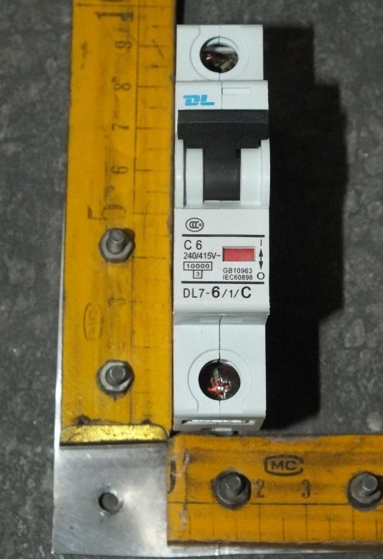
4 age 4 of 92 R e port ref. No.: C009-CB2012CQC ictures of product (1)

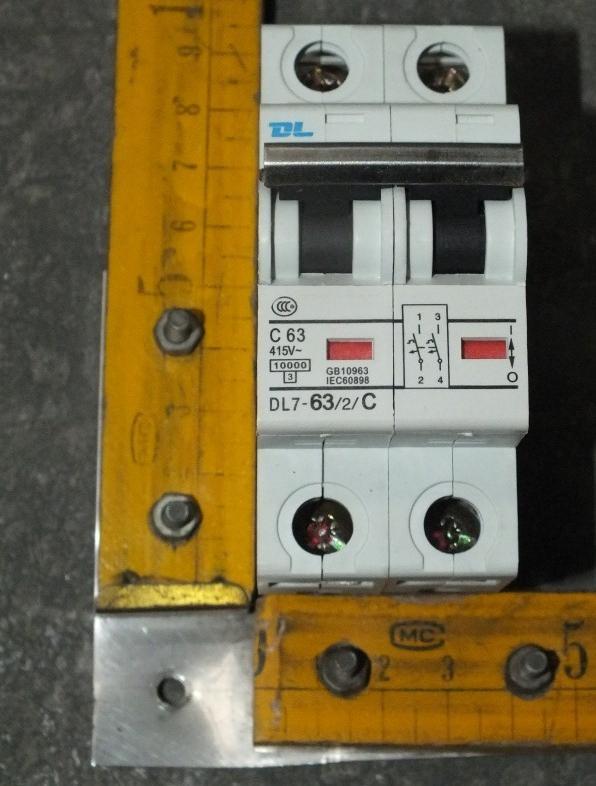
5 age 5 of 92 R e port ref. No.: C009-CB2012CQC ictures of product (2)

6 age 6 of 92 R e port ref. No.: C009-CB2012CQC ictures of product (3+N)

7 age 7 of 92 R e port ref. No.: C009-CB2012CQC ictures of product (3+N)

8 age 8 of 92 R e port ref. No.: C009-CB2012CQC ictures of product (Interior structure)
9 age 9 of 92 R e port ref. No.: C009-CB2012CQC Remark:/ List of Attachments (including a total number of pages in each attachment): / Summary of test results: Type Characteristics Number of poles Rated current Test sequence DL7 C 1 63A E 1, E 2 DL7 C 1 6A E 1, E 2 DL7 C 2 63A E 1, E 2 DL7 C 2 6A E 1, E 2 DL7 C 3+N 63A E 1, E 2 DL7 C 3+N 6A E 1, E 2 DL7 C 1 63A A, B, C 1, C 2, D 0 +D 1, DL7 C 1 6A D 0, DL7 C 1 10A D 0 DL7 C 1 16A D 0 DL7 C 1 20A D 0 DL7 C 1 25A D 0 DL7 C 1 32A D 0 DL7 C 1 40A D 0 DL7 C 1 50A D 0 DL7 C 2 63A C 2, DL7 C 3+N 63A A, B, C 1, C 2, D 0 +D 1,
10 age 10 of 92 R e port ref. No.: C009-CB2012CQC IEC Cl. Requirement Test Result Verdict 6 MARKING AND OTHER INFORMATION (DL7 C63 1) Circuit-breaker marked with: a) Manufacturer s name or trade mark... : DENROM b)type designation, catalogue number or other identification number... : DL7-63/1/C c) Rated voltage (V)... : 240/415 d) Rated current (A)... : 63 e) Rated frequency (Hz)... : f) Rated short circuit capacity (A)... : g) Wiring diagram h) Ambient air temperature, if different from 30 C i) Degree of protection, if different from I20 j) For D-type circuit-breakers: the maximum instantaneous tripping current, if higher than 20 In(see table 2) k) Rated impulse withstand voltage Uimp if it is 2,5 kv Symbol for instantaneous tripping current C Symbol for nature of supply Marking for rated current and for instantaneous tripping shall be readily visible when CB is installed Other marking shall be easily discernible The suitability for isolation, which is provided by all circuit-breakers of this standard, may be indicated by the symbol on the device Energy limiting class I 2 t characteristic (documentation) Symbols on supply and load terminal Terminal for neutral conductor N Earthing terminal if any (IEC ) On off position shall be clearly indicated 0 I - For push-button CB the off push-button shall either be red or be marked with the symbol 0 Red not used for other push-button This symbol shall be easily discernible
11 age 11 of 92 R e port ref. No.: C009-CB2012CQC IEC Cl. Requirement Test Result Verdict For CB with multiple current ratings, the maximum value is marked, the adjusted value indicated without ambiguity Marking shall be indelible and easily legible (not on removable parts), 15 s with water, 15 s with hexane (see cl. 8.3) 8. REQUIREMENTS FOR CONSTRUCTION AND OERATION (DL7 C63 1) General Mechanism The moving contact shall be mechanically coupled so that all poles make and break together, whether operated manually or automatically, even if an overload occurs on one pole only The switched neutral shall close before and open after the protected pole (s) Neutral pole having adequate making and breaking capacity and CB with independent manual operation: all poles operate together including neutral pole CB shall have a trip free mechanism It shall be possible to switch the CB on and off by hand No intermediate position of the contacts osition of contacts shall be indicated Indication visible from the outside If the indication is on the actuating means, it shall, when released, automatically take up or stay in the position corresponding to that of the moving contacts; operating means shall have two different rest positions, except that, for automatic operation, a third distinct rest position may be provided If a separate mechanical indicator is used to indicate the position of the main contacts, colour red shall be used for the on position and green for the off position. The action of the mechanism shall not be influenced by the position of enclosures If the cover is used as a guiding means for pushbutton, it shall not be possible to remove this button from the outside
12 age 12 of 92 R e port ref. No.: C009-CB2012CQC IEC Cl. Requirement Test Result Verdict Operating means securely fixed, not possible to remove them without a tool For the up-down operating means the contacts shall be closed by the up movement Clearances and creepage distances Clearances [mm] see table 4 1.between live parts (of the main circuits) which are separated when the CB is in off position... : 2.between live parts of different polarity... : 3.between circuits supplied from different sources, one of which being ELV or SELV... : 4. between live parts and - accessible surfaces of operating means... : 9,8mm - screws or other means for fixing covers... : - surface on which the base is mounted... : 14,1mm - screws or other means for fixing the circuit breaker... : - metal covers or boxes... : - other accessible metal parts... : 8,2mm - metal frames supporting the base (flush-type). : 5.between metal parts of mechanism and: - accessible metal parts... : - screws or other means for fixing the circuit breaker... : - metal frames supporting the base (flush type). : Creepage distances [mm] (see table 4) Material group IIIa 1.between live parts (of the main circuits) which are separated when the CB is in off position... : 2.between live parts of different polarity... : 3.between circuits supplied from different sources, one of which being ELV or SELV... : 4. between live parts and - accessible surfaces of operating means... : 10,4mm - screws or other means for fixing covers... : II I --
13 age 13 of 92 R e port ref. No.: C009-CB2012CQC IEC Cl. Requirement Test Result Verdict - surface on which the base is mounted... : - screws or other means for fixing the circuit breaker... : - metal covers or boxes... : - other accessible metal parts... : - metal frames supporting the base (flush-type). : 5.between metal parts of mechanism and: - accessible metal parts... : - screws or other means for fixing the circuit breaker... : - metal frames supporting the base (flush type). : Screws, current-carrying parts and connections Connections, withstand mechanical stresses occurring in normal use Screws for mounting of the CB not of the threadcutting type Test according to cl. 9.4: - 10 times (screw Ø / torque Nm) ØmmNm (see table 10) ØmmNm - 5 times (screw Ø / torque Nm) Ø 5 mm 2,0 Nm (see table 10) ØmmNm lug in connections tested by plugging in and pulling out five times After test connections have not become loose nor electrical function impaired Screws with a thread of insulating material ensured correct introduction Electrical connection: contact pressure not transmitted through insulating material, unless there is sufficient resilience in the metallic parts - copper - alloy 58% copper for worked cold parts - alloy 50% copper for other parts - other metal Terminals for external conductors Terminals ensure correct connection of conductors (Test acc. To cl. 9.5 or annex J or K)
14 age 14 of 92 R e port ref. No.: C009-CB2012CQC IEC Cl. Requirement Test Result Verdict 9.5 Torque Ø 5 mm 2,0 Nm ØmmNm ØmmNm max. sect. mm² ull test: min sect. _1 max sect. 25 ull 100 mm² mm² N for 1 min During the test conductor does not move noticeably min sect. 1 mm² Torque (2/3)= _1,33 Nm max sect. _25 mm 2 The conductor shows no damage Nominal cross-section from _ 1 to 25 mm² No of wires _ 7 Ø of wires _ 2,14 mm Torque (2/3) = 1,33Nm After the test no wire escaped outside Terminals allow the connection of conductors of the following cross-sectional areas: (table 5)
15 age 15 of 92 R e port ref. No.: C009-CB2012CQC IEC Cl. Requirement Test Result Verdict Rated current (A) Range of nominal cross sections to be clamped (mm²) 13 1 to 2,5 > to 4 > ,5 to 6 > ,5 to 10 > to 16 > to 25 > to 35 > to 50 It is required that, for current ratings up to and including 50 A terminals are designed to clamp solid conductors as well as rigid stranded conductors; the use of flexible conductors is permitted Nevertheless, it is permitted that terminals for conductors having cross-sections from 1 mm 2 up to 6 mm 2 are designed to clamp solid conductors only. 1 to 25 mm² Means for clamping the conductors in the terminals not serve to fix any other component (See test sub-clause 9.5) Terminals for I N 32 A allow the connection of conductors without special preparation Terminals shall have adequate mechanical strength; ISO thread or equivalent (See tests of sub-clause 9.4 and 9.5.1) Clamping of conductor without damage to the conductor (See test of sub-clause 9.5.2) Clamping of conductor between metal surfaces (See tests of sub-clause 9.4 and 9.5.1) Conductor shall not slip-out when the clamping screw or nuts are tightened (See test of subclause 9.5.3) Terminals shall be properly fixed. No work loose when the clamping screws or nuts are tightened or loosened (See test of sub-clause 9.4) Clamping screws or nuts of terminals for protective conductors adequately secured against accidental loosening Screws and nuts of terminals for external conductors shall be in engagement with a metal thread, and the screws shall not be of tapping screw type
16 age 16 of 92 R e port ref. No.: C009-CB2012CQC IEC Cl. Requirement Test Result Verdict Non interchangeability For circuit-breakers intended to be mounted on bases forming a unit therewith(plug-in or screw-in type) it shall not be possible, without the aid of a tool, to replace a circuit-breaker when mounted as for normal use by another of the same make having a higher rated current, compliance is checked by inspection lug-in type circuit-breakers, the holding in position of which does not depend solely on their plug-in connection(s), shall be reliable and have adequate stability lug-in type circuit-breakers, the holding in position of which does not depend solely on their plug-in connection(s) Compliance of the mechanical mounting is checked by the relevant test lug-in type circuit-breakers, the holding in position of which does depend solely on their plugin connection(s) Compliance of the mechanical mounting is checked by the relevant test rotection against electric shock Live parts not accessible in normal use For CB, other than plug-in type, external parts, other than screws and other means for fixing covers, which are accessible shall be of insulating material Unless the live parts are within an internal enclosure of insulating material: Lining - reliable fixed, - adequate thickness and - mechanical strength Inlet openings for cables shall be in insulating material or be provided with bushings or similar devices in insulating material Such device - shall be reliable fixed - shall have adequate mechanical strength For plug-in CB, external parts, other than screws and other means for fixing covers, which are accessible shall be in insulating material Metallic operating means insulated from live parts
17 age 17 of 92 R e port ref. No.: C009-CB2012CQC IEC Cl. Requirement Test Result Verdict Metal parts of the mechanism not accessible and insulated from accessible metal parts, metal frames (for flush-type), screws or other means for fixing the base Replacement of plug-in CB possible without touching live parts Lacquer or enamel not considered 9.6 Test of protection against electric shock Use of test finger so designed that each jointed can be turned through an angle of 90 with respect to the finger Circuit-breaker with enclosures of thermoplastic material are additional tested at 35 C for 1 min with a force of 75 N 8.10 Resistance to heat CB sufficiently resistant to heat 9.14 Test of resistance to heat Test: - without removable covers... 1 h (100 2) C - removable covers... 1 h (70 2) C After the test no access to live parts, marking still legible Ball pressure test for external parts of insulating material (parts retaining current-carrying parts and parts of the protective circuit in position) T = 125 C Ø of impression 2 mm Ball pressure test for external parts of insulating material (parts not retaining current-carrying parts and parts of the protective circuit in position T = (70 2) C or T = C = (40 2) C + max. temperature rise of sub-clause 8.8 Ø of impression 2 mm 8.11 Resistance to abnormal heat and to fire External parts of insulating material shall not ignite or spread fire under fault or overload conditions 9.15 Resistance to abnormal heat and to fire Glow wire test: No visible flame, no sustained glowing or flames and glowing extinguish within 30 s Impression: <1,5 mm
18 age 18 of 92 R e port ref. No.: C009-CB2012CQC IEC Cl. Requirement Test Result Verdict external parts retaining current-carrying parts and parts of the protective circuit in position... (960 15) C all other external parts... (650 10) C 8.12 Resistance to rusting Ferrous parts adequately protected against rusting 9.16 Test of resistance to rusting: - 10 min immersed in a cold chemical degreaser such as methyl-chloroform or refined petrol - 10 min immersed in a 10% solution of ammonium chloride in water at 20 C - 10 min at 95% humidity at 20 C - 10 min at 100 C No sign of rust TESTS B 3 samples (DL7 C63 1) B-1 B-2 B Dielectric properties and isolating capability CB shall have adequate dielectric properties and shall ensure isolation: Dielectric strength at power frequency Compliance is checked by the tests 9.7.1, and on circuit-breaker in new condition Isolating capability Circuit-breakers shall be suitable for isolation. Compliance is checked by the verification of compliance with the minimum clearances and creepage distances of item 1 of table 4 and by tests of and Dielectric strength at rated impulse withstand voltage (Uimp) Circuit-breakers shall adequately withstand impulse voltages. Compliance is checked by the tests of Test of dielectric properties and isolating capability Resistance to humidity reparation of the circuit-breaker for test Inlet openings, if any, are left open; if knock-outs are provided, one of them is opened Test conditions
19 age 19 of 92 R e port ref. No.: C009-CB2012CQC IEC Cl. Requirement Test Result Verdict The humidity treatment is carried out in humidity cabinet 91% to 95% and the temperature of the air between 20 C and 30 C Test procedure: The sample is kept in the cabinet for 48 h Condition of the circuit-breaker after the test After this treat, the sample show no damage within the meaning of this standard and shall withstand the tests of and Insulation resistance of the main circuit Rf = 93 % T = 24 C After an interval between 30 min and 60 min flowing this treatment, the insulation resistance is measured 5 s after application of a d.c. voltage of approximately 500 V, consecutively as follows: [MΩ] [MΩ] [MΩ] a) In off-position, between the terminals which are electrically connected together when the circuit-breaker is in the closed position 2 M b) in off-position, between each pole in turn and the others connected together 2 M c) in on-position, between all poles connected together and the frame 5 M d) between metal parts of mechanism and the frame 5 M e) between the frame and metal foil in contact with the inner surface of the internal enclosure or lining of insulating material 5 M Dielectric strength of the main circuit After the circuit-breakers have passed the tests of the test voltage specified in is applied for 1 min between the parts indicated in >500 >500 >500 >500 >500 >500 a) 2000 V b) 2000 V c) 2000 V d) 2000 V e) 2500 V Dielectric strength of the auxiliary and control circuits For these tests, the main circuit shall be connected to the frame. The test voltage specified in shall be applied for 1 min as follows: 1) Between all the auxiliary or control circuits and the frame U = _ V U = _ V
20 age 20 of 92 R e port ref. No.: C009-CB2012CQC IEC Cl. Requirement Test Result Verdict 2) Between each part of the auxiliary or control circuits which may be isolated from the other parts of the auxiliary or control circuits and these other parts connected together U = [1000 V if Ui 60 V or 2Ui V if Ui > 60 V] U = _ V Verification of the impulse withstand voltage (across clearances and across solid insulation) and leakage current across open contacts Verification of the impulse withstand voltage across open contacts (suitability for isolation) The 1,2/50µs impulse voltage shall be applied three times for each polarity at intervals of 1s minimum - rated impulse withstand voltage (kv) : 4kV -- - sea level of the laboratory: 12m -- - test Uimp on open main contacts (equipment -- suitable for isolating) (see table : Utest = 6,2 kv - no unintentional disruptive discharge during the test s Verification of impulse withstand voltage for the parts not test in The 1,2/50µs impulse voltage shall be applied three times for each polarity at intervals of 1s minimum - rated impulse withstand voltage (kv) : 4kV -- - sea level of the laboratory: 12m -- - test Uimp main circuits (see table 14) : Utest = 4,9 kv -- Application of test voltage -- i) Between all the phase pole(s) connected together and to the neutral pole (or path) of the circuit-breaker ii) Between all the phase pole(s) and the neutral pole(or path) connected together and the metal support connected to the terminals intended for the protective conductor(s) - no unintentional disruptive discharge during the test s Verification of leakage currents across open contacts(suitability for isolation) For circuit-breakers suitable for isolation, the leakage current shall be measured. Each pole having been submitted to the test of , or , or or is supplied at a test voltage of 1,1 times its rated operational voltage, the circuit-breaker being in the open position 457 V -- The leakage current flowing across the open contacts is measured and shall not exceed 2 ma 8.4 Temperature rise Temperature rise does not exceed the limiting values stated in table V: <0,03 <0,03 <0,03 sect. 16 mm² --
21 age 21 of 92 R e port ref. No.: C009-CB2012CQC IEC Cl. Requirement Test Result Verdict Test current: I N = (reach the steady-state value) Four-pole CB s: 1) three poles loaded 2) one pole and neutral pole loaded I N = 63A -- Ambient air temperature... : Tamb= arts... Temperature rise [K] [K] [K] [K] L1 _ L2 L3 L4(N) L3 N _ Terminals for external connections ~39 36~37 36~39 External parts liable to be touched during manual operation of the circuit-breaker, including operating means of insulating material and metallic means for coupling of insulating operating means of several poles External metallic parts of operating means _ Other external parts, including that face of the circuit-breaker is in direct contact with the mounting surface Measurement of power losses B-1 B-2 B-3 ower loss do not exceed the values stated in table 15 Test current: I N = 63 A (reach the steady state value) B-1 B-2 B-3 Loaded one pole after the other W W W
22 age 22 of 92 R e port ref. No.: C009-CB2012CQC IEC Cl. Requirement Test Result Verdict Max power loss: 13 W L1 L2 L3 L4(N) L3 N 6,93 6,74 6,68 _ 8.5 Uninterrupted duty day test Circuit-breakers operate reliable even after long service 28 cycles - 21 h with current - 3 h without current cross sectional area. 16 mm² During the test no tripping during the last period, temperature rise shall be measured I N = 63 A -- Ambient air temperature... : 23 C -- arts... Temperature rise [K] [K] [K] [K] Terminals for external connections The temperature rise does not exceed the value measured during the temperature rise test (subclause 8.8) by more than 15 K 41~43 40~43 41~45 Test current 1,45 I N =63A 91,4 A -- - Tripping within [s] [s] [s] - 1h ( 63 A) 8min27s 10min19s 11min36s - 2h (> 63 A) TESTS C 3 samples (DL7 C63 1) C 1-1 C 1-2 C Mechanical and electrical endurance Circuit-breaker shall be capable to perform an adequate number of cycles with rated current General test conditions
23 age 23 of 92 R e port ref. No.: C009-CB2012CQC IEC Cl. Requirement Test Result Verdict Test: Test Voltage 240 V (rated voltage) Test Current 63 A (rated current) ower factor (0,85-0,9) ar. Resistor Ohm Cross sect. area 16mm² Test procedure The circuit-breaker is submitted to 4000 operating cycles with rated current. 242V 63,2A 0,87 - I N 32 A: 2 s on 13 s off - I N 32 A: 2 s on 28 s off During the test the circuit-breaker shall be operated as in normal use Condition of the circuit-breaker after the test Following the test the sample shall not show: - undue wear - discrepancy between the position of the moving contacts and corresponding position of the Indicating device - damage to the enclosure permitting access to live parts by test finger (see 9.6) - loosening of electrical or mechanical connections - seepage of sealing compound Moreover test current... 2,55 I N 161A -- Opening time not less 1 s or more than [s] [s] [s] - 60 s ( 32 A) s ( 32 A) Dielectric strength reduced to 900 V (1500 V acc. IEC 60898) Test at reduced short-circuit currents Test on all circuit-breakers Test at reduced short-circuit currents: Fig. 3 Test current: Obtained A or 10 In I test= 634A -- Test voltage 1,05 Un U = 240V -- ower factor 0,93-0,98 0,
24 age 24 of 92 R e port ref. No.: C009-CB2012CQC IEC Cl. Requirement Test Result Verdict Test in free air copper wire F : 0,12 mm / 0,16 mm resistor R Test in enclosures : 0,75 Ohm / 1,5 Ohm copper wire F : 0,12 mm / 0,16 mm resistor R : 0,75 Ohm / 1,5 Ohm a = 35 mm 0,16mm 1,5 Ohm dimension of enclosure: xx mm I eak (A) max. value 854A 867A 854A Sequence: 6 x 0 and 3 x CO [ka 2 s] [ka 2 s] [ka 2 s] Max. I²t ka 2 s 3,43 3,61 3,23 - No permanent arcing - No flash-over between poles or between poles and frame - No blowing of the fuses F and F - olyethylene foil shows no holes After the test: Verification of the circuit-breaker after short-circuit tests The circuit-breakers shall show no damage impairing their further use and shall maintenance, withstand the following tests. a) leakage current across open contacts, according to , each pole is supplied at a voltage 1,1 times Un.= 264 V. The circuit breaker is in the open position C 1-1 (ma) C 1-2 (ma) C 1-3 (ma) The leakage current shall not exceed 2 ma L1 <0,01 <0,01 <0,01 Electric strength test: Test voltage 1500 V (see 8.7.2) L2 L3 L4(N) a) b) c) d) e) 2000 V Short-circuit test on circuit-breakers rated 230 V, or 240 V or 230/400 V for verifying for use in IT systems (DL7 C63 1)
25 age 25 of 92 R e port ref. No.: C009-CB2012CQC IEC Cl. Requirement Test Result Verdict Test current: A or 1,2 times the upper limit of the standard range of instantaneous tripping (see table 2 ) whichever is the higher, but < 2500 A. When Itripping exceed 20 In the current adjusted at 1,2 times the upper limit even when higher 2500 A Obtained I test= 766A -- Test voltage 1,05 Un U = 436 V -- ower factor 0,93-0,98 0, Test in free air copper wire F : 0,12 mm / 0,16 mm resistor R Test in enclosures : 0,75 Ohm / 1,5 Ohm copper wire F : 0,12 mm / 0,16 mm resistor R : 0,75 Ohm / 1,5 Ohm a = 35 mm 0,16mm 1,5 Ohm dimension of enclosure: xx mm I eak (A) max. value 1000A 1000A 998A Sequence: 0 + CO on each protected pole [ka 2 s] [ka 2 s] [ka 2 s] Shifted point 30 on the other protected pole C 2-1 C 2-2 C 2-3 Max. I²t ka 2 s L1 L2 L3 L4 - No permanent arcing - No flash-over between poles or between poles and frame - No blowing of the fuses F and F - olyethylene foil shows no holes After the test: The circuit-breakers shall show no damage impairing their further use and shall maintenance, withstand the following tests. a) leakage current across open contacts, according to , each pole is supplied at a voltage 1,1 times Un.= 456 V. The circuit breaker is in the open position The leakage current shall not exceed 2 ma L1 <0,01 <0,01 <0,01 L2 L3 L4(N) 3,97 C 2-1 3,83 C 2-2 3,65 C
26 age 26 of 92 R e port ref. No.: C009-CB2012CQC IEC Cl. Requirement Test Result Verdict Electric strength test: Test voltage 1500 V (see 8.7.2) a) b) c) d) e) 2000 V TESTS D 3 samples (DL7 C63 1) 8.6 Automatic operation Standard time-current zone Tripping characteristic of CB ensures adequate protection of the circuit, without premature operation Tests: DO D-1 D-2 D-3 I N (A) 63 Sect. (mm²) 16 Instantaneous tripping current B C D Test of time-current characteristic Test current 1,13 I N (A) starting from cold for: 71,2 A h (I N 63 A) >1 >1 >1-2 h (I N 63 A) No tripping Then steadily increased within 5 s to 1,45 I N (A) 91,4A -- - Tripping within [min] [min] [min] - 1h ( 63 A) 50min26s 43min13s 9min49s - 2h (> 63 A) Test current 2,55 I N (A) starting from cold for: 160 A -- opening time not less than 1 s or more than [s] [s] [s] - 60 s s Teast of instantaneous tripping and of correct opening of the contacts General test conditions For the lower values of the test current the test is made once, at any convenient voltage.
27 age 27 of 92 R e port ref. No.: C009-CB2012CQC IEC Cl. Requirement Test Result Verdict For the upper values of the test current the test is made at rated voltage Un( phase to neutral) with a power factor between 0,95 and 1. The sequence of operation is : O-CO-CO-CO Interval time: > 3 min The tripping time of the O operation is measured After each operation the indicating means shall show the open position of the contacts For circuit-breakers of the B Type Test current 3I N (A), starting from cold 242V 0,98 Opening time: [s] [s] [s] - 0,1s t 45s ( 32A) - 0,1s t 90s ( 32A) Test current 5 I N (A), starting from cold Tripping less than 0,1 s For circuit-breakers of the C Type Test current 5I N (A), starting from cold 315A -- Opening time: [s] [s] [s] - 0,1s t 15s ( 32A) - 0,1s t 30s ( 32A) Test current 10 I N (A), starting from cold 635A -- Tripping less than 0,1 s 6,32ms 11,5ms 10,0ms For circuit-breakers of the D Type Test current 10I N (A), starting from cold Opening time: [s] [s] [s] - 0,1s t 4s ( 32A) - 0,1s t 8s ( 32A) Test current 20 I N (A) or to the maximum instantaneous tripping current(see cl. 6, item j), starting from cold Tripping less than 0,1 s Test of effect of single pole loading on the tripping characteristic of multipole circuit-breakers: Test current 1,1 It (A), (two pole) starting from cold Tripping within [min] [min] [min] - 1h --
28 age 28 of 92 R e port ref. No.: C009-CB2012CQC IEC Cl. Requirement Test Result Verdict - 2h Test current 1,2 It (A), (three pole or four pole) starting from cold Tripping within [min] [min] [min] - 1h - 2h Test of effect of ambient temperature on the tripping characteristics a) Ambient temperature of (-5 2) C below the ambient air reference temperature T = -5 C -- Test current 1,13 I N (A) 71,2A -- - assed for 1h >1h >1h >1h - assed for 2h Current is then steadily increased to 1,9 I N (A) within 5s 120A -- Tripping within [min] [min] [min] - 1h 4min04s 8min51s 3min09s - 2h b) Ambient temperature of (40 2) C T = 40 C -- Test current I N (A) 63,0A -- No tripping within - 1h >1h >1h >1h - 2h Tests: D1 (DL7 C63 1) D-1 D-2 D Resistance to mechanical shock and impact CB shall have adequate mechanical behaviour so as to withstand the stresses imposed during installation and use Mechanical shock - 50 falls on two sides of vertical board C - Vertical board turned falls on two sides of vertical board C During the test the circuit-breakers shall not open Mechanical impact All types: - Impact test: 10 blows-height 10 cm, no damage
29 age 29 of 92 R e port ref. No.: C009-CB2012CQC IEC Cl. Requirement Test Result Verdict Screw-in types: - Torque 2,5 Nm for 1 min, no damage CB intended to be mounted on a rail lug-in types - downward vertical 50 N for 1 min - upward vertical 50 N for 1 min, no damage The circuit-breaker are mounted in there normal position, complete with plug-in base but without cables and any cover plate A force of 20 N applied for 1min to the circuitbreaker (see fig 17). During this test the circuit-breaker part shall not become loose from the base and shall not show damage impairing further use Test at 1500 A: rospective current of 1500 A power factor 0,93 to 0,98 rospective current obtained (A) 1,54/1,56kA -- ower factor 0,96/0,97 -- Test voltage 1,05 Un 252/436 V -- Test circuit: figure T (min) 3 min Test in free air copper wire F : 0,12 mm / 0,16 mm resistor R Test in enclosures : 0,75 Ohm / 1,5 Ohm copper wire F : 0,12 mm / 0,16 mm resistor R Sequence : 0,75 Ohm / 1,5 Ohm a = 35 mm 0,16mm 1,5 Ohm dimension of enclosure: xx mm 6 x O, 2 x CO, 1 x O I eak (A) max. value 1,93kA 1,90kA 1,91kA I²t ka 2 s [ka 2 s] [ka 2 s] [ka 2 s] Max. I²t ka 2 s L1 L2 L3 N - No permanent arcing - No flash-over between poles or between poles and frame 8,98 8,35 8,85 --
30 age 30 of 92 R e port ref. No.: C009-CB2012CQC IEC Cl. Requirement Test Result Verdict - No blowing of the fuses F and F - olyethylene foil shows no holes After the test: The circuit-breakers shall show no damage impairing their further use and shall maintenance, withstand the following tests. a) leakage current across open contacts, according to , each pole is supplied at a voltage 1,1 times Un.=456 V. The circuit breaker is in the open position The leakage current shall not exceed 2 ma L1 <0,01 <0,01 <0,01 Electric strength test: Test voltage 1500 V (see 8.7.2) L2 L3 L4(N) a) b) c) d) e) 2000 V Test current 0.85x non tripping current (1,13 I N ) 60,5A -- D-1 D-2 D-3 - assed for 1h > 1h > 1h > 1h - assed for 2h Current is then steadily increased to 1,1 x tripping current (1,45 I N ) within 5s D-1 [min] 100A -- D-2 [min] D-3 [min] Tripping within 1 hour / 2 hour 14min11s 5min09s 8min16s 9.10 Tests: DO (DL7 C6 1) DO 1 I N (A) 6 Sect. (mm²) 1 Instantaneous tripping current B C D Test of time-current characteristic Test current 1,13 I N (A) starting from cold for: 6,78 A h (I N 63 A) >1
31 age 31 of 92 R e port ref. No.: C009-CB2012CQC IEC Cl. Requirement Test Result Verdict - 2 h (I N 63 A) No tripping Then steadily increased within 5 s to 1,45 I N (A) 8,70 A -- - Tripping within [min] - 1h ( 63 A) 3min55s - 2h (> 63 A) Test current 2,55 I N (A) starting from cold for: 15,3 A -- opening time not less than 1 s or more than - 60 s s Teast of instantaneous tripping and of correct opening of the contacts General test conditions For the lower values of the test current the test is made once, at any convenient voltage. For the upper values of the test current the test is made at rated voltage Un( phase to neutral) with a power factor between 0,95 and 1. The sequence of operation is : O-CO-CO-CO Interval time: > 3 min The tripping time of the O operation is measured After each operation the indicating means shall show the open position of the contacts For circuit-breakers of the B Type Test current 3I N (A), starting from cold 242V 0,99 Opening time: [s] [s] [s] - 0,1s t 45s ( 32A) - 0,1s t 90s ( 32A) Test current 5 I N (A), starting from cold Tripping less than 0,1 s For circuit-breakers of the C Type Test current 5I N (A), starting from cold 30,0A -- Opening time: - 0,1s t 15s ( 32A) 6-0,1s t 30s ( 32A) Test current 10 I N (A), starting from cold 61,2A -- Tripping less than 0,1 s 17,3ms [s] [s] --
32 age 32 of 92 R e port ref. No.: C009-CB2012CQC IEC Cl. Requirement Test Result Verdict For circuit-breakers of the D Type Test current 10I N (A), starting from cold Opening time: [s] [s] [s] - 0,1s t 4s ( 32A) - 0,1s t 8s ( 32A) Test current 20 I N (A) or to the maximum instantaneous tripping current(see cl. 6, item j), starting from cold Tripping less than 0,1 s Test of effect of single pole loading on the tripping characteristic of multipole circuit-breakers: Test current 1,1 It (A), (two pole) starting from cold Tripping within [min] [min] [min] - 1h - 2h Test current 1,2 It (A), (three pole or four pole) starting from cold Tripping within [min] [min] [min] - 1h - 2h Test of effect of ambient temperature on the tripping characteristics a) Ambient temperature of (-5 2) C below the ambient air reference temperature T = -5 C -- Test current 1,13 I N (A) 6,78 A -- - assed for 1h >1h - assed for 2h Current is then steadily increased to 1,9 I N (A) within 5s Tripping within 11,4 A -- [min] - 1h 3min12s - 2h b) Ambient temperature of (40 2) C T = 40 C -- Test current I N (A) 6,00A -- No tripping within - 1h >1h - 2h
33 age 33 of 92 R e port ref. No.: C009-CB2012CQC IEC Cl. Requirement Test Result Verdict 9.10 Tests: DO (DL7 C10 1) DO 2 I N (A) 10 Sect. (mm²) 1,5 Instantaneous tripping current B C D Test of time-current characteristic Test current 1,13 I N (A) starting from cold for: 11,3 A h (I N 63 A) >1-2 h (I N 63 A) No tripping Then steadily increased within 5 s to 1,45 I N (A) 14,5 A -- - Tripping within [min] - 1h ( 63 A) 7min42s - 2h (> 63 A) Test current 2,55 I N (A) starting from cold for: 25,5 A -- opening time not less than 1 s or more than - 60 s s Teast of instantaneous tripping and of correct opening of the contacts General test conditions For the lower values of the test current the test is made once, at any convenient voltage. For the upper values of the test current the test is made at rated voltage Un( phase to neutral) with a power factor between 0,95 and 1. The sequence of operation is : O-CO-CO-CO Interval time: > 3 min The tripping time of the O operation is measured After each operation the indicating means shall show the open position of the contacts For circuit-breakers of the B Type Test current 3I N (A), starting from cold 242V 0,99 Opening time: [s] [s] [s] - 0,1s t 45s ( 32A) - 0,1s t 90s ( 32A) Test current 5 I N (A), starting from cold Tripping less than 0,1 s [s] --
34 age 34 of 92 R e port ref. No.: C009-CB2012CQC IEC Cl. Requirement Test Result Verdict For circuit-breakers of the C Type Test current 5I N (A), starting from cold 50,0A -- Opening time: - 0,1s t 15s ( 32A) 4-0,1s t 30s ( 32A) Test current 10 I N (A), starting from cold 102A -- Tripping less than 0,1 s 14,5 ms For circuit-breakers of the D Type Test current 10I N (A), starting from cold Opening time: [s] [s] [s] - 0,1s t 4s ( 32A) - 0,1s t 8s ( 32A) Test current 20 I N (A) or to the maximum instantaneous tripping current(see cl. 6, item j), starting from cold Tripping less than 0,1 s Test of effect of single pole loading on the tripping characteristic of multipole circuit-breakers: Test current 1,1 It (A), (two pole) starting from cold Tripping within [min] [min] [min] - 1h - 2h Test current 1,2 It (A), (three pole or four pole) starting from cold Tripping within [min] [min] [min] - 1h - 2h Test of effect of ambient temperature on the tripping characteristics a) Ambient temperature of (-5 2) C below the ambient air reference temperature [s] T = -5 C -- Test current 1,13 I N (A) 11,3 A -- - assed for 1h >1h - assed for 2h Current is then steadily increased to 1,9 I N (A) within 5s 19,0 A --
35 age 35 of 92 R e port ref. No.: C009-CB2012CQC IEC Cl. Requirement Test Result Verdict Tripping within [min] - 1h 4min17s - 2h b) Ambient temperature of (40 2) C T = 40 C -- Test current I N (A) 10,0A -- No tripping within - 1h >1h - 2h 9.10 Tests: DO (DL7 C16 1) DO 3 I N (A) 16 Sect. (mm²) 2,5 Instantaneous tripping current B C D Test of time-current characteristic Test current 1,13 I N (A) starting from cold for: 18,1 A h (I N 63 A) >1-2 h (I N 63 A) No tripping Then steadily increased within 5 s to 1,45 I N (A) 23,2 A -- - Tripping within [min] - 1h ( 63 A) 29s - 2h (> 63 A) Test current 2,55 I N (A) starting from cold for: 40,8 A -- opening time not less than 1 s or more than - 60 s s Teast of instantaneous tripping and of correct opening of the contacts General test conditions For the lower values of the test current the test is made once, at any convenient voltage. For the upper values of the test current the test is made at rated voltage Un( phase to neutral) with a power factor between 0,95 and 1. The sequence of operation is : O-CO-CO-CO Interval time: > 3 min The tripping time of the O operation is measured 242V 0,99 [s] --
36 age 36 of 92 R e port ref. No.: C009-CB2012CQC IEC Cl. Requirement Test Result Verdict After each operation the indicating means shall show the open position of the contacts For circuit-breakers of the B Type Test current 3I N (A), starting from cold Opening time: [s] [s] [s] - 0,1s t 45s ( 32A) - 0,1s t 90s ( 32A) Test current 5 I N (A), starting from cold Tripping less than 0,1 s For circuit-breakers of the C Type Test current 5I N (A), starting from cold 80,0A -- Opening time: - 0,1s t 15s ( 32A) 4-0,1s t 30s ( 32A) Test current 10 I N (A), starting from cold 165A -- Tripping less than 0,1 s 8,11ms For circuit-breakers of the D Type Test current 10I N (A), starting from cold Opening time: [s] [s] [s] - 0,1s t 4s ( 32A) - 0,1s t 8s ( 32A) Test current 20 I N (A) or to the maximum instantaneous tripping current(see cl. 6, item j), starting from cold Tripping less than 0,1 s Test of effect of single pole loading on the tripping characteristic of multipole circuit-breakers: Test current 1,1 It (A), (two pole) starting from cold Tripping within [min] [min] [min] - 1h - 2h Test current 1,2 It (A), (three pole or four pole) starting from cold Tripping within [min] [min] [min] - 1h - 2h [s]
37 age 37 of 92 R e port ref. No.: C009-CB2012CQC IEC Cl. Requirement Test Result Verdict Test of effect of ambient temperature on the tripping characteristics a) Ambient temperature of (-5 2) C below the ambient air reference temperature T = -5 C -- Test current 1,13 I N (A) 18,1 A -- - assed for 1h >1h - assed for 2h Current is then steadily increased to 1,9 I N (A) within 5s Tripping within 30,4 A -- [min] - 1h 19s - 2h b) Ambient temperature of (40 2) C T = 40 C -- Test current I N (A) 16,0A -- No tripping within - 1h >1h - 2h 9.10 Tests: DO (DL7 C20 1) DO 4 I N (A) 20 Sect. (mm²) 2,5 Instantaneous tripping current B C D Test of time-current characteristic Test current 1,13 I N (A) starting from cold for: 22,6 A h (I N 63 A) >1-2 h (I N 63 A) No tripping Then steadily increased within 5 s to 1,45 I N (A) 29,0 A -- - Tripping within [min] - 1h ( 63 A) 43s - 2h (> 63 A) Test current 2,55 I N (A) starting from cold for: 51,0 A -- opening time not less than 1 s or more than [s] - 60 s s
38 age 38 of 92 R e port ref. No.: C009-CB2012CQC IEC Cl. Requirement Test Result Verdict Teast of instantaneous tripping and of correct opening of the contacts General test conditions For the lower values of the test current the test is made once, at any convenient voltage. For the upper values of the test current the test is made at rated voltage Un( phase to neutral) with a power factor between 0,95 and 1. The sequence of operation is : O-CO-CO-CO Interval time: > 3 min The tripping time of the O operation is measured After each operation the indicating means shall show the open position of the contacts For circuit-breakers of the B Type Test current 3I N (A), starting from cold 242V 0,98 Opening time: [s] [s] [s] - 0,1s t 45s ( 32A) - 0,1s t 90s ( 32A) Test current 5 I N (A), starting from cold Tripping less than 0,1 s For circuit-breakers of the C Type Test current 5I N (A), starting from cold 100A -- Opening time: - 0,1s t 15s ( 32A) 5-0,1s t 30s ( 32A) Test current 10 I N (A), starting from cold 204A -- Tripping less than 0,1 s 8,55ms For circuit-breakers of the D Type Test current 10I N (A), starting from cold Opening time: [s] [s] [s] - 0,1s t 4s ( 32A) - 0,1s t 8s ( 32A) Test current 20 I N (A) or to the maximum instantaneous tripping current(see cl. 6, item j), starting from cold Tripping less than 0,1 s Test of effect of single pole loading on the tripping characteristic of multipole circuit-breakers: [s] --
39 age 39 of 92 R e port ref. No.: C009-CB2012CQC IEC Cl. Requirement Test Result Verdict Test current 1,1 It (A), (two pole) starting from cold Tripping within [min] [min] [min] - 1h - 2h Test current 1,2 It (A), (three pole or four pole) starting from cold Tripping within [min] [min] [min] - 1h - 2h Test of effect of ambient temperature on the tripping characteristics a) Ambient temperature of (-5 2) C below the ambient air reference temperature T = -5 C -- Test current 1,13 I N (A) 22,6 A -- - assed for 1h >1h - assed for 2h Current is then steadily increased to 1,9 I N (A) within 5s Tripping within 38,0 A -- [min] - 1h 18s - 2h b) Ambient temperature of (40 2) C T = 40 C -- Test current I N (A) 20,0A -- No tripping within - 1h >1h - 2h 9.10 Tests: DO (DL7 C25 1) DO 5 I N (A) 25 Sect. (mm²) 4 Instantaneous tripping current B C D Test of time-current characteristic Test current 1,13 I N (A) starting from cold for: 28,3 A h (I N 63 A) >1-2 h (I N 63 A) No tripping
40 age 40 of 92 R e port ref. No.: C009-CB2012CQC IEC Cl. Requirement Test Result Verdict Then steadily increased within 5 s to 1,45 I N (A) 36,3A -- - Tripping within [min] - 1h ( 63 A) 38s - 2h (> 63 A) Test current 2,55 I N (A) starting from cold for: 63,8 A -- opening time not less than 1 s or more than - 60 s s Teast of instantaneous tripping and of correct opening of the contacts General test conditions For the lower values of the test current the test is made once, at any convenient voltage. For the upper values of the test current the test is made at rated voltage Un( phase to neutral) with a power factor between 0,95 and 1. The sequence of operation is : O-CO-CO-CO Interval time: > 3 min The tripping time of the O operation is measured After each operation the indicating means shall show the open position of the contacts For circuit-breakers of the B Type Test current 3I N (A), starting from cold 242V 0,98 Opening time: [s] [s] [s] - 0,1s t 45s ( 32A) - 0,1s t 90s ( 32A) Test current 5 I N (A), starting from cold Tripping less than 0,1 s For circuit-breakers of the C Type Test current 5I N (A), starting from cold 125A -- Opening time: - 0,1s t 15s ( 32A) 7-0,1s t 30s ( 32A) Test current 10 I N (A), starting from cold 256A -- Tripping less than 0,1 s 14,1ms For circuit-breakers of the D Type Test current 10I N (A), starting from cold [s] [s] --
41 age 41 of 92 R e port ref. No.: C009-CB2012CQC IEC Cl. Requirement Test Result Verdict Opening time: [s] [s] [s] - 0,1s t 4s ( 32A) - 0,1s t 8s ( 32A) Test current 20 I N (A) or to the maximum instantaneous tripping current(see cl. 6, item j), starting from cold Tripping less than 0,1 s Test of effect of single pole loading on the tripping characteristic of multipole circuit-breakers: Test current 1,1 It (A), (two pole) starting from cold Tripping within [min] [min] [min] - 1h - 2h Test current 1,2 It (A), (three pole or four pole) starting from cold Tripping within [min] [min] [min] - 1h - 2h Test of effect of ambient temperature on the tripping characteristics a) Ambient temperature of (-5 2) C below the ambient air reference temperature T = -5 C -- Test current 1,13 I N (A) 28,3A -- - assed for 1h >1h - assed for 2h Current is then steadily increased to 1,9 I N (A) within 5s Tripping within 47,5A -- [min] - 1h 13s - 2h b) Ambient temperature of (40 2) C T = 40 C -- Test current I N (A) 25,0A -- No tripping within - 1h >1h - 2h
42 age 42 of 92 R e port ref. No.: C009-CB2012CQC IEC Cl. Requirement Test Result Verdict 9.10 Tests: DO (DL7 C32 1) DO 6 I N (A) 32 Sect. (mm²) 6 Instantaneous tripping current B C D Test of time-current characteristic Test current 1,13 I N (A) starting from cold for: 36,2 A h (I N 63 A) >1-2 h (I N 63 A) No tripping Then steadily increased within 5 s to 1,45 I N (A) 46,4 A -- - Tripping within [min] - 1h ( 63 A) 1min17s - 2h (> 63 A) Test current 2,55 I N (A) starting from cold for: 81,6 A -- opening time not less than 1 s or more than - 60 s s Teast of instantaneous tripping and of correct opening of the contacts General test conditions For the lower values of the test current the test is made once, at any convenient voltage. For the upper values of the test current the test is made at rated voltage Un( phase to neutral) with a power factor between 0,95 and 1. The sequence of operation is : O-CO-CO-CO Interval time: > 3 min The tripping time of the O operation is measured After each operation the indicating means shall show the open position of the contacts For circuit-breakers of the B Type Test current 3I N (A), starting from cold 242V 0,98 Opening time: [s] [s] [s] - 0,1s t 45s ( 32A) - 0,1s t 90s ( 32A) Test current 5 I N (A), starting from cold Tripping less than 0,1 s [s] --
43 age 43 of 92 R e port ref. No.: C009-CB2012CQC IEC Cl. Requirement Test Result Verdict For circuit-breakers of the C Type Test current 5I N (A), starting from cold 160A -- Opening time: - 0,1s t 15s ( 32A) 6-0,1s t 30s ( 32A) Test current 10 I N (A), starting from cold 326A -- Tripping less than 0,1 s 7,14ms For circuit-breakers of the D Type Test current 10I N (A), starting from cold Opening time: [s] [s] [s] - 0,1s t 4s ( 32A) - 0,1s t 8s ( 32A) Test current 20 I N (A) or to the maximum instantaneous tripping current(see cl. 6, item j), starting from cold Tripping less than 0,1 s Test of effect of single pole loading on the tripping characteristic of multipole circuit-breakers: Test current 1,1 It (A), (two pole) starting from cold Tripping within [min] [min] [min] - 1h - 2h Test current 1,2 It (A), (three pole or four pole) starting from cold Tripping within [min] [min] [min] - 1h - 2h Test of effect of ambient temperature on the tripping characteristics a) Ambient temperature of (-5 2) C below the ambient air reference temperature [s] T = -5 C -- Test current 1,13 I N (A) 36,2 A -- - assed for 1h >1h - assed for 2h Current is then steadily increased to 1,9 I N (A) within 5s 60,8 A --
TEST REPORT IEC/EN Circuit-breakers for over current protection for household and similar installations
 Test Report issued under the responsibility of: TEST REORT IEC/EN 60898-1 Circuit-breakers for over current protection for household and similar installations Report Reference No.... : 130100913SHA-004
Test Report issued under the responsibility of: SHA-001 Date of issue... : Total number of pages... : 292. Report Number...
 D Test Report issued under the responsibility of: TEST REORT Residual current operated circuit-breakers without integral overcurrent protection for household and similar uses (RCCBs) art 1: General rules
Test Report issued under the responsibility of: Report Number...: B Date of issue...: Total number of pages...
 Test Report issued under the responsibility of: TEST REORT Residual current operated circuit-breakers without integral overcurrent protection for household and similar uses (RCCBs) art 1: General rules
TeSys circuit-breakers
 Presentation Thermal-magnetic motor circuit-breakers types GV2, GV and GV7 GV2-ME, GV2-P, GV-ME and GV7-R motor circuit-breakers are -pole thermal-magnetic circuit-breakers specifically designed for the
C120N circuit-breakers B, C and D curves EN 60898/EN 61009: IEC : 10 ka
 C0N circuit-breakers B, C and D curves EN 09/EN 009: 0000 - IEC 097-: 0 ka function # protection of cables against overloads and short-circuits in final distribution # manual control and isolation # earth
AC Motor capacitor. Part 1: General Performance, testing and rating Safety requirements Guide for installation and operation
 Test Report issued under the responsibility of: TEST REORT A.C. motor capacitors art 1: General erformance, testing and rating Safety requirements Guide for installation and operation Report Reference
Thermal-Magnetic Circuit Breaker 2210-T2...
 Thermal-Magnetic Circuit Breaker 0-T... Description One, two and three pole thermal-magnetic circuit breakers with trip-free mechanism and toggle actuation (S-type TM CBE to EN 6094/IEC 94). Featuring
5SJ4...-.HG Circuit Breakers to IEC and UL 489
 Siemens AG 009 5SJ...-.HG Circuit Breakers to IEC and UL 89 BETA Low-Voltage Circuit Protection Compliance with industry standards is a must in today's manufacturing environment. Worldwide acceptance is
Sealing possibility Electrical endurance (ops) Mechanical endurance (ops) Overvoltage category Standards
 Mechanical endurance (ops) Overvoltage category Standards") Miniature circuit breaker ETIMAT 7,7 0.5 Rated voltage Rated current Rated frequency Rated short-circuit capacity Energy limiting class characteristic Build-in width Mounting on the rail 0/00 V AC, max.
Miniature circuit breaker ETIMAT 7,7 0.5 Rated voltage Rated current Rated frequency Rated short-circuit capacity Energy limiting class characteristic Build-in width Mounting on the rail 0/00 V AC, max.
Magnetic and Hydraulic-Magnetic Circuit Breaker 8340-T...
 Magnetic and Hydraulic-Magnetic Circuit Breaker 830-T... Description ngle, two and three pole magnetic and hydraulic-magnetic circuit breakers with trip-free mechanism and toggle actuation. A choice of
Photobiological safety of lamps and lamp systems
 Test Report issued under the responsibility of: TEST REORT hotobiological safety of lamps and lamp systems Report Reference No.... : Dialight Optics Lab Request #16119 Date of issue... : 9/22/2016 Total
C60N circuit breakers0 B, C and D curves IEC 60898: 6000 A, IEC : 10 ka
 C0N circuit breakers0 B, C and s IEC 0898: 000 A, IEC 097-: 0 ka Function b The circuit-breakers combine the following functions: v protection of circuits against short-circuit currents v protection of
ISOCON-6. 24V AC or DC POWERED ISOLATING SIGNAL CONVERTER
 ISOCON-6 24V AC or DC POWERED ISOLATING SIGNAL CONVERTER Whilst every effort has been taken to ensure the accuracy of this document, we accept no responsibility for damage, injury, loss or expense resulting
MCB NB1-63H Miniature Circuit Breaker
 NB-H Miniature Circuit Breaker. General. Function protection of circuits against short-circuit currents, protection of circuits against overload currents, switch, isolation, NB-H circuit-breakers are used
LD-LP-LL-LC Rope Safety Switches with reset for emergency stop
 TECHNICA DATASHEET D-P--C Rope Safety Switches with reset for emergency stop Metal or polymer housing, from one or three conduit entries Protection degree IP6 In conformity with EN ISO 13850 contact blocks
INSTITUTE OF TESTING AND CERTIFICATION (INDIA) PVT.LTD.
 PVT.LTD.") (INDIA) VT.LTD. 60598-1 Requirement Result/Remarks Verdict 2.2 2.3 2.4 2.5 3.2.1 3.2.2 3.2.3 3.2.4 3.2.5 3.2.6 3.2.7 3.2.8 3.2.9 2 Classification of Luminaries Classification according to type of protection
(INDIA) VT.LTD. 60598-1 Requirement Result/Remarks Verdict 2.2 2.3 2.4 2.5 3.2.1 3.2.2 3.2.3 3.2.4 3.2.5 3.2.6 3.2.7 3.2.8 3.2.9 2 Classification of Luminaries Classification according to type of protection
Issued August DATA SHEET. 3VT3 MCCB up to 630 A
 ssued August 9 DATA SHEET VT MCCB up to 6 A Based on Siemens Catalog V 6 8 Circuit breakers Switch disconnectors Technical specifications Specifications Type VT 76-AA6/6/56-AA, VT 76-AA6/6/56-AA Circuit
BETA Protecting. Low-Voltage Fuse Systems. LV HRC fuse links. 3/36 Siemens ET B1 2008
 LV HRC fuse links Overview LV HRC fuses are used for installation systems in non-residential, commercial and industrial buildings as well as in switchboards of power supply companies. They therefore protect
90 MCB MODULAR CIRCUIT BREAKERS FOR CIRCUIT PROTECTION
 MCB - MTC - MT - MTHP Technical data TYPE MTC MT MTC45 MTC60 MTC100 MT 45 MT 60 Rated current (In) (A) 2-32 6-32 6-32 6-40 1-63 Utilization category A A A A A Rated operational voltage (Ue) (V) 230/400-240/415
90 MCB range Modular circuit breakers for circuit protection
 MCB - MTC - MT - MTHP Technical data TYPE MTC MT MTC45 MTC60 MTC100 MT 45 MT 60 Rated current (In) (A) 2-32 6-32 6-32 6-40 1-63 Utilization category A A A A A Rated operational voltage (Ue) (V) 230 / 400
Request Ensure that this Instruction Manual is delivered to the end users and the maintenance manager.
 Request Ensure that this Instruction Manual is delivered to the end users and the maintenance manager. 1 -A - Introduction - Thank for your purchasing MITSUBISHI ELECTRIC MELPRO TM D Series Digital Protection
Thermal-Magnetic Circuit Breaker 2210-S2..
 Thermal-Magnetic Circuit Breaker -S.. Description One, two and three pole thermal-magnetic circuit breakers with trip-free mechanism and toggle actuation (S-type TM CBE to EN 60934/IEC 934). Designed for
Thermal-Magnetic Circuit Breaker 2210-S2..
 Thermal-Magnetic Circuit Breaker -S.. Description One, two and three pole thermal-magnetic circuit breakers with trip free mechanism and toggle actuation (S-type TM CBE to EN 6094/IEC 94). Designed for
Thermal-Magnetic Circuit Breaker 2210-S2...
 Thermal-Magnetic Circuit Breaker 0-S... Description One, two and three pole thermal-magnetic circuit breakers with trip free mechanism and toggle actuation (S-type TM CBE to EN 60934/IEC 934). Designed
TEST REPORT IEC Photobiological safety of lamps and lamp systems
 Test Report issued under the responsibility of: TEST REORT hotobiological safety of lamps and lamp systems Report Reference No.... : 17-12-07 Date of issue... : 2017-12-18 Total number of pages... : 19
Thermal-Magnetic Circuit Breaker 2210-S2...
 Description One, two and three pole thermal-magnetic circuit breakers with trip free mechanism and toggle actuation (S-type TM CBE to EN 6094/IEC 94). Designed for panel or plug-in mounting. Available
Thermal-Magnetic Circuit Breaker 2210-S2..
 Thermal-Magnetic Circuit Breaker -S.. Description One, two and three pole thermal-magnetic circuit breakers with trip free mechanism and toggle actuation (S-type TM CBE to EN 60934/IEC 934). Designed for
FAZ tripping characteristics at 30 C: B, C, D to IEC/EN FAZ tripping characteristics at 30 C: R to IEC/EN
 FAZ, AZ High-Capacity Tripping Characteristics Moeller HPL011-001/00 1/07 FAZ tripping characteristics at 0 C: B, C, D to IEC/EN 0 9 FAZ tripping characteristics at 0 C: R to IEC/EN 0 97 t [s] 700 00 100
ISOCON-3 MAINS POWERED ISOLATING SIGNAL CONVERTER
 ISOCON-3 MAINS POWERED ISOLATING SIGNAL CONVERTER CAUTION: This equipment is designed for connection to mains voltages and must be used in accordance with this guide. If it is not, the safety protection
Varius SUMMARY OF MODELS OF HRC FUSE-LINKS
 SUMMARY OF MODELS OF HRC FUSE-LINKS Type PNA000 PHNA000 PNA00 PHNA00 Rated current I n up to A up to 0 A up to A up to 0 A Rated voltage U n AC 00 V, 00 V 90 V 00 V 90 V DC 0 V 0 V 0 V 0 V Fuse-link size
For the electronic measurement of current: DC, AC, pulsed..., with galvanic separation between the primary and the secondary circuit.
 Current Transducer LDSR 0.3-TP/SP1 I P R N = 300 ma For the electronic measurement of current: DC, AC, pulsed..., with galvanic separation between the primary and the secondary circuit. Features Closed
THE DIMENSIONING OF ELECTRICAL CONDUCTORS FOR USE IN "PANEL BOARDS" ADDRESSED TO HAZARDOUS AREAS - PART THREE
 July 04 THE DIMENSIONING OF ELECTRICAL CONDUCTORS FOR USE IN "PANEL BOARDS" ADDRESSED TO HAZARDOUS AREAS - PART THREE In this third part. we want to speak about how important is the correct sizing of the
Universal limit switches
 SWITCHES.CROUZET.COM 1 LIMIT SWITCHES 0/016 Universal limit switches 8384 standard 8384 with positive break operation Conformity to standards IEC / EN 60947--1, including Annex K for version with positive
TEST CERTIFICATES OR REPORTS ISSUED BY VEIKI-VNL LTD.
 Page 2 of 29 TEST CERTIFICATES OR REPORTS ISSUED BY LTD. Type Test Certificate of Complete Type Test This certificate provides the verification of all the rated characteristics of the equipment as assigned
TEST REPORT IEC Photobiological safety of lamps and lamp systems
 age 1 of 20 Test Report issued under the responsibility of: Intertek Testing Services Shenzhen Ltd. TEST REORT hotobiological safety of lamps and lamp systems Report Reference No.... : 140729054GZU-002
To order, specify : Types Protection functions Current surge Asymmetry and loss of phase. Operating principle
 otor protection relays - T - FWIT Since % of -phase motor failures are due to load problems or loss of phase, the CROUZET range of motor protection relays is indispensable! models give motor protection
E8EB-N0C2B E8EB-N0B2B
 Slim Sensor CSM DS_E 1 Ideal for Workpiece Position and Original Checking The to 1 kpa model can be used for workpiece position checking. The to 1MPa model is ideal for original pressure checking. Degree
VX25 Enclosure System. Technical documentation PE conductor connection, current carrying capacity
 VX Enclosure System Technical documentation PE conductor connection, current carrying capacity Enclosure system VX Contents Contents. General remarks. Introduction. Notes on the design of the earthing
Issued August DATA SHEET. 3VT5 MCCB up to 1600 A
 ssued August 9 DATA SHEET VT5 MCCB up to 0 A Based on Siemens Catalog V 8 Standard circuit breakers Releases Technical specifications Specifications VT5 circuit breakers Switch disconnectors Type Standards
Siemens AG Miniature Circuit Breakers. Totally Integrated Power SENTRON. Configuration. Edition 10/2014. Manual. siemens.
 Siemens AG 05 Totally Integrated Power SENTRON Configuration Manual Edition 0/0 siemens.com/lowvoltage Siemens AG 05 Siemens AG 05 Introduction 5SL miniature circuit breakers 5SY and 5SP miniature circuit
08/072 PKZ2 Motor-Protective Circuit-Breakers Tripping Characteristics
 0/07 PKZ Tripping Characteristics Moeller HPL0-00/00 S-PKZ high-capacity contact module, SEA-PKZ contact module Normal switching duty AC-/00V kw A Rated output of three-phase motors 0...0 Hz. 7..... 0.7
Photobiological safety of lamps and lamp systems
 Test Report issued under the responsibility of: age 1 of 14 TEST REORT hotobiological safety of lamps and lamp systems Report Reference No.... : GZES111000681631 Tested by (name + signature)... : Bica
F F FAULT CURRENT Prospective. 1. Introduction. 2. Types of fault conditions
 FAULT CURRENT F F13-13 FAULT CURRENT - Contents 1. Introduction 2. Types of fault conditions 3 fault current must be determined 3.1 Purposes for which of prospective fault current magnitudes are used 3.2
TEST REPORT IEC and/or EN Photobiological safety of lamps and lamp systems
 Test Report issued under the responsibility of: TEST REORT IEC 62471 and/or EN 62471 hotobiological safety of lamps and lamp systems Report Reference No.... : GZES130300236831 Tested by (name + signature)...
M I N I S T R Y O F C O M M U N I C A T I O N S T E L E C O M M U N I C A T I O N S S E C T O R T E C H N I C A L S T A N D A R D F O R
 M I N I S T R Y O F C O M M U N I C A T I O N S T E L E C O M M U N I C A T I O N S S E C T O R T E C H N I C A L S T A N D A R D F O R M A T E R I A L S N O. G 2 0 : 1 0 : 0 0 1 : 1 8 J U M P E R W I
Photobiological safety of lamps and lamp systems
 Test Report issued under the responsibility of: TEST REORT hotobiological safety of lamps and lamp systems Report Reference No.... : GZES130300220831 Date of issue... : 2013-04-07 Total number of pages...
TEST REPORT IEC Photobiological safety of lamps and lamp systems
 TEST REORT hotobiological safety of lamps and lamp systems Report Reference No.... : Date of issue... : Total number of pages... : Testing Laboratory... : Address... : Applicant s name... : Address...
TEST REPORT IEC Photobiological safety of lamps and lamp systems
 Test Report issued under the responsibility of: TEST REORT hotobiological safety of lamps and lamp systems Report Reference No.... : 4326246.51 Date of issue... : 2016-02-23 Total number of pages... :
Page 2 of 14 Report Ref. No
 age 2 of 14 Summary of testing: Tests performed (name of test and test clause): Clause 6.1, Initial measurements: - MST 01: Visual inspection - 10.2: Maximum power determination - MST 16: Dielectric withstand
16 Input AC Block I/O Module
 6 Input AC Module Cat. No. 79-6A0 Series B Installation Mount the block I/O module in a vertical (recommended) or horizontal position. Allow sufficient room around the block for cooling air flow through
Telemando Reconectadores automáticos compactos
 18 Telemando Reconectadores automáticos compactos Nº de polos IDn (ma) Intensidad (A) Referencia.V.. 2 30 300 40 MT53RA2A040030 198,80 63 MT53RA2A063030 219,70 40 MT53RA2A040300 213,00 63 MT53RA2A063300
RS INDUSTRY LIMITED. RS Chip Array ESD Suppressor APPROVAL SHEET. Customer Information. Part No. : Model No. : COMPANY PURCHASE R&D
 APPROVAL SHEET Customer Information Customer : Part Name : Part No. : Model No. : COMPANY PURCHASE R&D Vendor Information Name: RS INDUSTRY LIMITED Part Name ARRAY TYPE MULTILAYER VARISTOR Part No. RS
X T O B P 1 6 B C 1 S
 9 Overload Relays XTOB, XTOT May 07 Contents Description Page Overload Relays XTOB, XTOT Selection................ 9 Product Selection.......... 95 Accessories............... 9 Technical Data and Specifications............
TEST REPORT ENVIRONMENTAL TESTING
 Report No.: 19616025 001 Page 2 of 13 Report reference No... : 19616025 001 TEST REPORT ENVIRONMENTAL TESTING Tested by (printed name and signature)... : (see cover page) Approved by (printed name and
5SP and 5SY Supplementary Protection UL 1077
 Product Guide 5SP and 5SY Supplementary Protection UL 077 for North merican and International applications usa.siemens.com/5sy Table of contents Certifications, standards, features and description Characteristic
H i g h A m p e r a g e 2 5 t o A M P. T y p e I & I I I V e h i c l e P r o t e c t i o n. I P 6 7 W a t e r p r o o f
 H i g h A m p e r a g e 2 5 t o 3 0 0 A M P T y p e I & I I I V e h i c l e P r o t e c t i o n I P 6 7 W a t e r p r o o f I g n i t i o n - P r o t e c t e d S A E & A B Y C C o m p l i a n t L E D T
Masterpact. Installation recommendations
 90 Installation recommendations Presentation Functions and characteristics 9 Dimensions and connection 5 Electrical diagrams 8 Operating conditions 92 Installation in switchboard 9 Door interlock catch
WK25V, WK20V, WK12V, WK08V, WK06V. Thick Film High Voltage Chip Resistors. Size 2512, 2010,1206, 0805, 0603
 WK25V, WK20V, WK12V, WK08V, WK06V ±5%, ±2%, ±1%, ±0.5% Thick Film High Voltage Chip Resistors Size 2512, 2010,1206, 0805, 0603 *Contents in this sheet are subject to change without prior notice. Page 1
Film Capacitors. EMI suppression capacitors. Date: June 2018
 Film Capacitors EMI suppression capacitors Date: June 2018 EPCOS AG 2018. Reproduction, publication and dissemination of this publication, enclosures hereto and the information contained therein without
General characteristics, Products
 The Feature Packed line of Manual Motor Protectors Eaton s new XT family of Manual Motor Protectors (MMPs) features a pushbutton or rotary ON/OFF manual disconnect, Class adjustable bimetallic overload
Report No 247/ This Report consists of 41 pages
 Test Report Report No 247/ 7340511 This Report consists of 41 pages Client Electrical Safety Council 18 Buckingham Gate London SW1E 6LB Authority & date BSI Estimate Acceptance No 0000191154 dated 12 March
DATA SHEET. 88 Longteng Road, Economic & Technical Development Zone, Kunshan, Jiangsu, China
 DATA SHEET Product Name Complete Pb-Free Thick Film Chip Resistors Part Name PF Series Uniroyal Electronics Global Co., Ltd. 88 Longteng Road, Economic & Technical Development Zone, Kunshan, Jiangsu, China
SolderSleeve Devices Specification For Commercial Wire Splices. Table of Contents
 Page 1 of 15 SolderSleeve Devices Specification For Commercial Wire Splices Table of Contents Chapter Pages 1.0 General Requirements 1.1 Design of the Electrical Connection-Reminder Concerning The Approval
Semiconductor (AC) fuses
 fuses") PSC gr sizes 7x - 690 VAC Main characteristics 6,9 grb 71 PA 200 6,9 grb 73 TTF 1000 + MS7V1-5 UR Ferraz Shawmut PSC-gRB 690 VAC fuse-links provide maximum flexibility in equipment design and ultimate
PSC gr sizes 7x - 690 VAC Main characteristics 6,9 grb 71 PA 200 6,9 grb 73 TTF 1000 + MS7V1-5 UR Ferraz Shawmut PSC-gRB 690 VAC fuse-links provide maximum flexibility in equipment design and ultimate
Overload Relays. SIRIUS 3RU1 Thermal Overload Relays. 3RU11 for standard applications. 5/46 Siemens LV 1 AO 2011
 SIRIUS 3RU1 Thermal Overview 1 2 7 3 4 6 "Increased safety" type of EEx e according to ATEX directive 94/9/EC The 3RU11 thermal overload relays are suitable for the overload of explosion-proof motors with
Instruction. Vacuum Circuit Breaker Operator Module. Type 3AH 4.16kV to 38kV. Power Transmission & Distribution
 Instruction 0001-22-2--00 Vacuum Circuit Breaker Operator Module Type 3AH 4.16kV to 38kV Power Transmission & Distribution Hazardous voltages and high-speed moving parts. Will cause death, serious injury
FL ballasts Electronic fixed output. PC TC PRO sr 1/2x11 42 W PC PRO compact
 FL ballasts EL HE PC TC PRO sr 1/2x11 42 W PC PRO compact Product description CELMA Energy Efficiency Index A2 BAT / A2 T Nominal life-time up to 50,000 h (at ta 50 C with a failure rate max. 0.2 % per
WW12C, WW08C, WW06C, WW04C, WW02C. Low ohm chip resistors ( power ) Size 1206, 0805, 0603, 0402, 0201
 Size 1206, 0805, 0603, 0402, 0201") WW12C, WW08C, WW06C, WW04C, WW02C ±5%, ±1%, ±0.5% Low ohm chip resistors ( power ) Size 1206, 0805, 0603, 0402, 0201 *Contents in this sheet are subject to change without prior notice. Page 1 of 8 ASC_WWxxC_V05
WW12C, WW08C, WW06C, WW04C, WW02C ±5%, ±1%, ±0.5% Low ohm chip resistors ( power ) Size 1206, 0805, 0603, 0402, 0201 *Contents in this sheet are subject to change without prior notice. Page 1 of 8 ASC_WWxxC_V05
Amphenol C 091 A/B/D. Circular Connectors. Amphenol-Tuchel Electronics GmbH
 Amphenol C 091 A/B/D Circular Connectors Amphenol-Tuchel Electronics GmbH General information These connectors are designed and produced in conformity with the low-voltage directive (/3/EWG) respectively
TEST REPORT IEC / EN Photobiological safety of lamps and lamp systems
 age 1 of 22 TEST REORT hotobiological safety of lamps and lamp systems Report Reference No...: 3006889.51-QUA/LI Date of issue...: 2011-03-08 Total number of pages...: Testing Laboratory...: Address...:
UL 1077 DIN Rail Supplementary Protectors
 UL 0 DIN Rail Supplementary Protectors Product Overview UL 0 DIN Rail Supplementary Protectors PRODUCT OVERVIEW Product Overview Standard Features WMZS breaker terminals provide finger and back-of-hand
Product Data Sheet PD-0053-A
 Product Data Sheet PD-0053-A 3M Mini D Ribbon (MDR) Connector MDR Surface Mount 102XX-1210 XE 102XX-1S10 XE Page: 1 of 11 Table of Contents 1.0 SCOPE...2 2.0 PRODUCT TESTED...2 3.0 GENERAL CONDITIONS...2
Amphenol. Amphenol-Tuchel Electronics GmbH. Circular Connectors C 091 A/B/D Series
 Amphenol Amphenol-Tuchel Electronics GmbH Circular Connectors C 09 A/B/D Series The Company Amphenol-Tuchel Electronics GmbH is a member of the USA based Amphenol Corporation. With our own global presence
16 Appendix 16 Electrical Research Association Report
 Guide to the Wiring Regulations 16 Appendix 16 Electrical Research Association Report (ERA) report on armoured cables with external CPCs The attached report was commissioned by the ECA and is copyright
32 Input AC Block I/O Module
 Input AC Module Cat. No. 79-A0 Series B Installation Mount the block I/O module in a vertical (recommended) or horizontal position. Allow sufficient room around the block for cooling air to flow through
BETA Protecting Miniature Circuit Breakers
 Siemens AG 00 / Product overview / High-capacity range 000 A 0000 A 0000 A, high current 0000 A, universal current 000 A ka /0 Comfort range with plug-in terminal / Compact range +N in MW / Additional
High Precision Thick Film chip resistors. Size 1206, 0805, 0603, 0402, 0201
 WK2K, WK08K, WK06K, WK04K, WK02K ±.0%, ±0.5% Thick Film TC50/TC00 High Precision Thick Film chip resistors Size 206, 0805, 0603, 0402, 020 Page of 7 ASC_WKxxK_V07 NOV- 205 FEATURE. SMD Thick film resistor
Photobiological safety of lamps and lamp systems
 age 1 of 27 Test Report issued under the responsibility of: Intertek Testing Services Shenzhen Ltd. Guangzhou Branch TEST REORT IEC 62471 hotobiological safety of lamps and lamp systems Report Reference
TEST REPORT IEC and/or EN Photobiological safety of lamps and lamp systems
 Test Report issued under the responsibility of: TEST REORT and/or EN 62471 hotobiological safety of lamps and lamp systems Report Reference No.... : GZES160200176431 Tested by (name + signature)... : Jack
Redline Unibis : the solution Circuit protection
 2 circuits in 1 mo Redline Unibis : the solution ircuit protection Unibis compact Ms are one of the latest introductions in the Redline range and are developed to reduce the size of the distribution board
CGS ALUMINUM ELECTROLYTIC CAPACITORS
 CGS ALUMINUM ELECTROLYTIC CAPACITORS EXTREME APPLICATON HIGHLIGHTS APPLICATION Capacitance 50-500,000µF U.P.S Systems Voltage 15 to 500 WVDc Inverters/P.C.U.s. -10%, + 20% Tolerance and Motor Special Controls
Product Data Sheet PD-0037-B
 Product Data Sheet PD-0037-B 3M Shielded Compact Ribbon (SCR) Connector 3M Shielded Compact Ribbon (SCR) Boardmount Right Angle 36110-2220 XX 3 Electronic Solutions Division Page: 1 of 12 Table of Contents
Alternating Current (AC): Alternating Current is electric current that reverses directions at regular intervals.
: Alternating Current is electric current that reverses directions at regular intervals.") Glossary Alternating Current (AC): Alternating Current is electric current that reverses directions at regular intervals. American National Standards Institute (ANSI): American National Standards Institute
Glossary Alternating Current (AC): Alternating Current is electric current that reverses directions at regular intervals. American National Standards Institute (ANSI): American National Standards Institute
This product/component/material was tested to determine the levels of the six hazardous substances in accordance with the standard
 Test Report issued under the responsibility of: CTS Co., Ltd. 501, Samsung Techno-park, 97, Jungbu-daero 448beon-gil, Yeongtong-gu, Suwon-si, Gyeonggido, Korea TEST REPORT Procedures for the determination
CAPACITORS, FIXED, TUBULAR, POROUS TANTALUM CATHODE AND ANODE, GELLED ELECTROLYTE, HERMETICALLY SEALED BASED ON TYPE ST79
 Pages 1 to 15 CAPACITORS, FIXED, TUBULAR, POROUS TANTALUM CATHODE AND ANODE, GELLED ELECTROLYTE, HERMETICALLY SEALED BASED ON TYPE ST79 Issue 1 November 2007 Document Custodian: European Space Agency -
Impedance relay and protection assemblies
 RXZK 21H, 22H, 23H 509 006-BEN Page 1 Issued June 1999 Changed since July 1998 Data subject to change without notice (SE970175) (SE970184) Features Micro-processor based impedance relay with R and X settings
General characteristics
 General characteristics This range of insulators and partition bushings provides for connecting and supporting low- and medium-voltage electrical equipment. - Their purpose is to provide electrical and
ATyS Automatic and remotely operated transfer switches from 125 to 3200 A
 atys-p_001_b atys_d_001_a_1_cat ATyS p I-0-II 4P ATyS d I-0-II 4P Function The ATyS are three-phase motorised transfer switches with positive break indication. They enable the on load transfer of two three-phase
DC Film Capacitors MKT Radial Lacquered Type
 l 467 w FEATURES Available taped and loose in box RoHS compliant Seating plane (1) h APPLICATIONS Blocking and coupling, bypass and energy reservoir. α (2) l t REFERENCE STANDARDS IEC 60384-2 MARKING C-value;
Semiconductor (AC) fuses
 fuses") gr 690 VAC sizes 000 to (full range) Ferraz Shawmut PROTISTOR NH grb 690 VAC fuselinks provide maximum flexibility in equipment design and ultimate protection for today s power conversion equipment. This
gr 690 VAC sizes 000 to (full range) Ferraz Shawmut PROTISTOR NH grb 690 VAC fuselinks provide maximum flexibility in equipment design and ultimate protection for today s power conversion equipment. This
1. Explain the various methods of methods of grounding. In power system, grounding or earthing means connecting frame of electrical equipment (non-cur
 1. Explain the various methods of methods of grounding. In power system, grounding or earthing means connecting frame of electrical equipment (non-current carrying part) or some electrical part of the
DC Film Capacitors MKT Axial Type
 MKT181 DC Film Capacitors MKT Axial Type FEATURES Supplied loose in box, taped on ammopack or reel Material categorization: For definitions of compliance please see www.vishay.com/doc?9991 APPLICATIONS
TECHNICAL INFORMATION
 TECHNICAL INFORMATION RATED PRIMARY OLTAGE () This is the supply assigned to the transformer by the manufacturer. RATED SECONDARY OLTAGE () This is the secondary output assigned to the transformer when
FEATURES APPLICATIONS DESCRIPTION QUICK REFERENCE DATA. PILKOR components
 FEATURES Excellent anti-surge characteristics Stable characteristics to moisture resistance even in high resistance range. Good replacement for ceramic plate resistors. APPLICATIONS Telecommunication Industrial
3VT4 Molded Case Circuit Breakers up to 1000 A
 VT4 Molded Case Circuit Breakers up to 00 A Catalog Technical nformation VT4 Molded Case Circuit Breakers up to 00 A General data / - Overview Circuit breakers Switch disconnectors / - Selection and ordering
APPROVAL SHEET FOR AL. ELECTROLYTIC CAPACITORS
 NO : ED-A5540 TO : APPROVED APPROVAL SHEET FOR AL. ELECTROLYTIC CAPACITORS : BY: Series Description Part No. HV series, PLEASE RETURN US ONE COPY YOUR SIGED SPECIFICATION AFTER YOU APPROVED OF IT. APPROVED
Ref: HLSR 16-PW; HLSR 32-PW; HLSR 40-PW-000; HLSR 50-PW-000,
 Digital Current Transducer HLSR-PW series I P N = 16... 50 A Ref: HLSR 16-PW; HLSR 32-PW; HLSR 40-PW-000; HLSR 50-PW-000, Bitstream output from on onboard Sigma Delta modulator. For the electronic measurement
東莞永力電業有限公司 YUNG LI CO., LTD REVISION RECORD YUNG LI. Customer : Parts No. : Draw No. : CY-U0003 TC02CCCCYY-95 CUSTOMER APPROVED
 東莞永力電業有限公司 YUNG LI CO., LTD Da Pu Industrial Zone, Gang Zi, Changping Town, Dong Guan City, Guangdong 523571 China.P.R.C TEL:0769-3396797~8 E-mail: sales@yung-li.com FAX:0769-3396796 Description : YP-11/YC-13
TEST REPORT REPORT NO.: QAV PAGE: 1 OF 31
 QAV Technologies Sdn. Bhd. (616788-U) 116, Lintang Kampung Jawa, NFIZ 3, Taman erindustrian Bayan Lepas, MK 12, 11900 enang, Malaysia. Tel No : 604 643 8317 Fax No : 604 643 8597 Email : qavtech@qavtech.com