TEST CERTIFICATES OR REPORTS ISSUED BY VEIKI-VNL LTD.
|
|
|
- Ralph Gregory
- 5 years ago
- Views:
Transcription
1
2 Page 2 of 29 TEST CERTIFICATES OR REPORTS ISSUED BY LTD. Type Test Certificate of Complete Type Test This certificate provides the verification of all the rated characteristics of the equipment as assigned by the manufacturer, by means of the performance of all type tests specified by the standards. Type Test Certificate of Dielectric Performance This certificate provides the verification of all dielectric ratings, by means of the performance of the appropriate type tests specified by the standards. Type Test Certificate of Temperature-Rise Performance This certificate provides the verification of temperature-rise limits together with measurement of the main circuit resistance, by means of the performance of the appropriate type tests specified by the standards. Type Test Certificate of Short-Circuit / Making and Breaking Performance This certificate provides the verification of rated characteristics with respect short-circuit and/or making and breaking performance, by means of the performance of the appropriate type tests specified by the standards. Type Test Certificate of Switching Performance This certificate provides the verification of the switching ratings (e.g. capacitive current), by means of the performance of the appropriate type tests specified by the standards. Type Test Report This report provides the verification of the rated characteristics of the equipment as assigned by the manufacturer, by means of the performance of the appropriate type tests specified by the standards, for type tests not indicated above. Development Test Report This report is issued when the test is intended only to provide the Client with information about the performance of the equipment. The tests are performed in accordance with relevant standards, but are not intended to verify compliance of the equipment. Control Test Report This report is issued for tests performed on equipment in service, or removed from service. Tests are performed, and compliance is evaluated in accordance with relevant standards. Test Report Test report is issued in all cases not listed above.
3 Page 3 of 29 Ratings/characteristics assigned by the manufacturer: Test Object: Designation: Manufacturer: Creepage distance: Spacing: Diameter of the insulating part: Dry lightning impulse withstand voltage: One unit: 5 units: Wet power frequency withstand voltage: One unit: 5 units: Puncture voltage: Specified mechanical failing load (SML): Residual strength Cap and pin type glass insulator U120BP Lviv Insulator Company Ltd. 445 mm 146 mm 280 mm 125 kv 465 kv 50 kv 180 kv 130 kv 120 kn 96 kn The tests were carried out in accordance with the following standards: IEC :1993 Insulators for overhead lines with a nominal voltage above 1000 V - Part 1: Ceramic or glass insulator units for a.c. systems - Definitions. test methods and acceptance criteria IEC 61211:2005 Insulators of ceramic material or glass for overhead lines with a nominal voltage greater than 1000 V. Impulse puncture testing in air IEC 60797:1984 Residual strength of string insulator units of glass or ceramic material for overhead lines after mechanical damage of the dielectric IEC 60437:1997 Radio interference test on high-voltage insulators IEC :1989 IEC 61467:2008 High-voltage test techniques. Part 1: General definitions and test requirements Insulators for overhead lines Insulator strings and sets for lines with a nominal voltage greater than 1000 V AC power arc tests Requirements of manufacturer or purchaser: List of manufacturer's drawings attached to this document: И-675A U120BP Present at the test in charge of manufacturer or purchaser: Mrs. Olena Artamonova Lviv Insulator Company Ltd. Mr. Sergiy Oleksandrenko Lviv Insulator Company Ltd. Mr. Yuriy Korynevskyy Lviv Insulator Company Ltd.
4 Page 4 of 29 TESTS PERFORMED ON THE TEST OBJECT No. Description Relevant clauses of the standard I. Sample tests 1 Verification of the dimensions IEC :1993 Clause 17 2 Verification of the displacements IEC :1993 Clause 21 3 Verification of the locking system IEC :1993 Clause 22 4 Thermal shock test IEC :1993 Clause 24 5 Galvanizing test IEC :1993 Clause 26 6 Mechanical failing load test IEC :1993 Clause 19 7 Puncture withstand test IEC :1993 Clause 15 II. Type Tests 1.1 Dry lightning impulse withstand voltage test on short standard string IEC :1993 Clause Dry lightning impulse withstand voltage test on one unit IEC :1993 Clause Wet power frequency withstand voltage test on short standard string IEC :1993 Clause Wet power frequency withstand voltage test on one unit IEC :1993 Clause 14 3 Mechanical failing load test IEC :1993 Clause 19 4 Thermal mechanical performance test IEC :1993 Clause 20 III. Special tests 1 R.I.V. test IEC 60437: Residual strength test IEC 60797: Impulse puncture test in air IEC 61211: Power arc test IEC 61467:2008
5 Page 5 of 29 DESCRIPTION OF THE TESTS I. Sample tests I.1. Verification of dimensions I.1.1. Test method and parameters Checking of the dimensions was carried out on samples E1+E2 (7 insulator units). The dimensions of the insulators were checked with manufacturer s drawing. The checked dimensions were within the tolerance. I.1.2. Test results The results are summarized in Table 1. The insulators passed the test. Sample Nos: Diameter (mm) Spacing (mm) Creepage distance (mm) Specified by IEC IEC ± ± ±19.3 E I.2 Verification of the displacements E E E E E E Table 1 Summary of test results of the tests I.2.1. Test method and parameters The axial and radial displacements were checked in accordance with clause Clause 21 of IEC :1993. Tests were performed on samples E1+E2 (7 insulator units) Variation on axial displacement: 11.2 mm Variation on radial displacement: 8.4 mm
6 Page 6 of 29 I.2.2. Test results The results are summarized in Table 2 and the test arrangement can be seen on Photo 2. The insulators passed the test. Axial displacement Radial displacement Sample No. A (mm) B (mm) I.3 Verification of the locking system Table 2 Summary of test results of the tests I.3.1. Test method and parameters Conformity of the looking device with the requirements of clause 22 of IEC (1993). No uncoupling shall occur during the verification of locking. The load F was applied three times in succession to move the locking device from the locking to the coupling position. The disengagement force shall be between 50 N and 500 N. Tests were performed on samples E2 (3 insulator units). I.3.2. Test results The test procedure can be seen on Diagram 1 and on Photo 1. The results are summarized in Table 3. The insulators passed the test. Sample Load disengagement force (N) No. 1 st 2 nd 3 rd Table 3 Summary of test results of the tests
7 Page 7 of 29 Unit E3 1st seria Force [N] :01 0:02 I.4 Thermal shock test 0:04 0:05 0:07 0:08 0:10 0:11 0:13 0:14 0:16 0:17 0:19 0:20 0:22 0:23 Time [m:s] Diagram 1 0:25 0:26 0:28 0:29 0:31 0:32 0:34 0:35 0:37 0:38 0:40 0:41 0:43 0:44 0:46 0:47 I.4.1. Test method and parameters Thermal shock test was carried out in accordance with clause 16 of IEC (1993). Tests were performed on samples E2 (3 insulator units) according to Table 4. Failure of any of the 3 insulators shall not occur. Sample No: Temperature of hot oven ( C) Temperature of water bath ( C) Table 4 Parameters of test results of the tests I.4.2. Test results Failure of any of the 3 insulators were not occurred. The insulators passed the test. I.5 Galvanizing test I.5.1 Test method and parameters The appearance of the zinc coating on the sample insulators was visually inspected. The coating thickness on the pin and on the cap of insulators was determined by a magnetic measuring device. Tests were performed on samples E2 (3 insulator units).
8 Page 8 of 29 I.5.2. Test results The results are summarized in Table 5. The insulators passed the test. Thickness of zinc coating (µm) Sample No. Pin Cap Average value Average value Acceptance criteria 85 I.6 Mechanical failing load test Table 5 Summary of test results of the tests I.6.1. Test method and parameters The tensile load was increased rapidly but smoothly form zero to app. 75% of SML and then gradually increased in a time between 15 s to 45 s. Finally the tensile load of the insulators was measured. I.6.2. Test results Failure was not occurred during the tensile load test at 100% of the SML (120 kn). Test were performed on samples E1 (4 insulator units), the insulators were broken at load between 131 and 151 kn. The test procedure can be seen on Diagram 2 and on Photo 4. The results are summarized in Table 6. The insulators passed the test. Unit No. Mechanical failing load (kn) Fracture pattern Broken cap Broken cap Broken cap Broken cap Average (X) Acceptance criteria Deviation (σ) 9.53 X SML + C 0 σ Coefficient (C 1 ) > IEC 383 Passed Table 6 Summary of test results of the tests
9 Page 9 of 29 Unit Force [kn] :00 0:02 I.7 Puncture withstand test 0:04 0:06 0:08 0:10 0:12 0:14 0:16 0:18 0:20 0:22 0:24 0:26 0:28 0:30 0:32 Time [m:s] Diagram 2 0:34 0:36 0:38 0:40 0:42 0:44 0:46 0:48 0:50 0:52 0:54 0:56 0:58 1:00 1:02 1:04 I.7.1. Test method and parameters The test objects were subjected to a puncture test in accordance with clause 15 of IEC (1993). A glass container filled with transformer oil was used for the test. I.7.2. Test results The test was carried out on sample E2 ( 3 insulator units). The results are summarized in Table 7. The insulators passed the test. Sample Nos: Measured puncture voltage (kv) Specified puncture voltage (kv) Remark none none none Table 7 Summary of test results of the tests
10 Page 10 of 29 II. Type tests II.1. Dry lightning impulse withstand voltage test During the tests the ambient parameters were: Dry/wet temperature: 19.5/14.0 C Air pressure: kpa II.1.1. Test on on short standard insulator string II Test method and parameters The test was carried out on 1 short standard string (5 units) by a test voltage of 465 kv peak with application of the correction factor. During the withstand test 15 positive and negative impulses of / µs were applied (shown in the attached oscillogram Nos.: 8790, The test object shall withstand 15 impulses on each polarity without breakdown or with not more than two flashovers according to referred standard. The correction factor was K= during the tests. II Test results The short standard string passed the impulse voltage withstand test without breakdown and without flashover on each polarity. II.1.2. Test on one unit II Test method and parameters The test was carried out on 3 samples by a test voltage of 125 kv peak with application of the correction factor. During the withstand test 15 positive and negative impulses of / µs were applied (shown in the attached oscillogram Nos.: 8619, The test object shall withstand 15 impulses on each polarity without breakdown or with not more than two flashovers according to referred standard. The correction factor was K= during the tests. II Test results The short standard string passed the impulse voltage withstand test without breakdown and without flashover on each polarity.
11 Page 11 of 29 II.2. Wet power frequency withstand voltage test During the tests the ambient parameters were: Dry/wet temperature: 19.5/14.0 C Air pressure: kpa Characterisation of the artificial rain: Vertical and horizontal component of the rain mm/min Resistivity of water 9500 Ωcm Direction of the rain to the insulator 45 II.2.1. Test on short standard insulator string II Test method and parameters The wet power frequency voltage test was carried out on 5 units by a test voltage of 180 kv rms with application of the correction factor for 1 minute in wet condition. The test object shall withstand the test voltage for 1 minute without breakdown and without flashovers. The sample was pre wetted for 15 minutes before the wet test. The form of the artificial rain was drop. During the test the insulator was continuously wetted. The correction factor was K= during the test. II Test results During the withstand test on short standard string neither flashover nor breakdown occurred at test voltage of 180 kv rms for 1 minute. The insulators passed the test. II.2.2. Test on one unit II Test method and parameters The wet power frequency voltage test was carried out on 3 samples by a test voltage of 50 kv rms with application of the correction factor for 1 minute in wet condition. The test objects shall withstand the test voltage for 1 minute without breakdown and without flashovers. The samples was pre wetted for 15 minutes before the wet test. The form of the artificial rain was drop. During the test the insulator was continuously wetted. The correction factor was K= during the test. II Test results During the withstand test on short standard string neither flashover nor breakdown occurred at test voltage of 50 kv rms for 1 minute. The insulators passed the test.
12 Page 12 of 29 III.3. Mechanical failing load test II.3.1. Test method and parameters The tensile load was increased rapidly but smoothly form zero to app. 75% of SML and then gradually increased in a time between 15 s to 45 s. Finally the tensile load of the insulators was measured. II Test results Failure was not occurred during the tensile load test at 100% of the SML (120 kn). Test were performed on 10 insulators, the insulators were broken at load between 130 and 151 kn. The test procedure can be seen on Diagram 3 and on Photo 4. The results are summarized in Table 8. The insulators passed the test. Unit No. Mechanical failing load (kn) Fracture pattern Broken cap Broken cap Broken cap Broken cap Broken cap Broken cap Broken cap Broken cap Broken cap Broken cap Average (X) Acceptance criteria Deviation (σ) 5.48 X SML + C 0 σ Coefficient (C 0 ) > IEC 383 Table 8 Summary of test results of the tests Passed
13 Page 13 of 29 Unit Force [kn] :00 0:02 II.4. Thermal-mechanical test 0:04 0:06 0:08 0:10 0:12 0:14 0:16 0:18 0:20 0:22 0:24 0:26 0:28 Time [m:s] Diagram 3 0:30 0:32 0:34 0:36 0:38 0:40 0:42 0:44 0:46 0:48 0:50 0:52 0:54 II.4.1. Test method and parameters The thermal-mechanical test was performed on 10 insulators. The test consisted of four cycles, where one cycle was hours (-30 ±5 C; +40 ±5 C). The applied tensile load was 62.5 % of the SML. The test arrangement can be seen on Photo 3. II Test results Failure was not occurred during the thermal-cycle test. After the withstand test the insulators were broken at loads between 132 and 151 kn. The results are summarized in Table 9. The insulators passed the test. Unit No. Mechanical failing load (kn) Fracture pattern 1 Broken glass and pin 141 pulled out Broken cap Broken cap Broken cap Broken cap Broken cap Broken cap Broken cap Broken cap Broken cap Average (X) 142 Acceptance criteria Deviation (σ) 5.94 Coefficient (C 0 ) 0.72 Table 9 Summary of test results of the tests X SML + C 0 σ 142> The test was passed
14 Page 14 of 29 III. Special tests III.1.R.I.V. test III.1.1. Test method and parameters The radio interference voltage on the insulator set was tested in accordance with IEC The tests were carried out on 1 MHz. The condenser was Zs= pf. The radio interference voltage should be expressed according to the standard referred as db across a resistance of 300 omhs, therefore R=300 ohms was set on the coupling four pole, in this way a phase angle not exceeding 20 between Zs and R was fulfilled. In accordance with IEC the radio interference voltage was recorded in course of runs and was plotted versus the applied voltage: the curve obtained was the radio interference characteristic of the insulator set. III.1.2. Test results The RIV values were 0 db on all ten samples and these were measured at the test voltage of 10 kv rms. The RIV values were between 20 dβ and 58 db on all ten samples and these were measured at the test voltage of 20 kv rms. The RIV values were between 65 db and 82 db at the test voltage of 30 kv. The values were less than the specified maximum of 86 db at the test voltage of 30 kv. The insulators passed the test. The test arrangement is shown on Photo 9. III.2.Residual strenght test III.2.1. Test method and parameters The residual strength test was performed on 25 insulators. The temperature cycle test consisted of three cycles where one cycle was minutes with 70 K temperature difference (82 C water bath; 12 C cold water bath). After three cycles, the glass of the insulators was broken off. After the preparation of the test pieces the residual strength test was performed on the metal parts of the insulators. The load was increased until failing occurred. III.2.2. Test results Failure did not occur during the temperature cycle test. The metal parts of insulators were broken at loads between 120 kn and 139 kn. The test arrangement is shown on Photo 5. The test procedure can be seen on Diagram 4. The results are summarized in Table 10 and can be seen on Photo 6. The insulators passed the test.
15 Page 15 of 29 Unit No. Mechanical failing load (kn) Fracture pattern All pieces Without broken pieces 1R 135 Broken cap 2R Pin pulled out 3R Pin pulled out 4R Pin pulled out 5R Pin pulled out 6R Pin pulled out 7R Pin pulled out 8R 127 Broken cap 9R Pin pulled out 10R Pin pulled out 11R Pin pulled out 12R Pin pulled out 13R Pin pulled out 14R Pin pulled out 15R Pin pulled out 16R Pin pulled out 17R 133 Broken cap 18R Pin pulled out 19R Pin pulled out 20R Pin pulled out 21R 136 Broken cap 22R Pin pulled out 23R Pin pulled out 24R Pin pulled out 25R Pin pulled out Average (X) Acceptance criteria Deviation (σ) k 0.65 Constant (k) > 0.65 (X σ)/SML passed Table 10 Summary of test results of the tests
16 Page 16 of 29 Unit 10. Force [kn] :00 0:02 0:04 III.3. Impulse puncture test in air 0:06 0:08 0:10 0:12 0:14 0:16 0:18 0:20 0:22 0:24 0:26 0:28 0:30 0:32 0:34 0:36 0:38 Time [m:s] Diagram 4 0:40 0:42 0:44 0:46 0:48 0:50 0:52 0:54 0:56 0:58 1:00 1:02 1:04 1:06 1:08 1:10 1:12 1:14 1:16 III.3.1. Test method and parameters The 50% flashover voltage value on 1 short standard string (5 units) was determined with up and down test method. After the up and down test method the 50% flashover voltage was dividing by the number of units, and the results was multiply with 2.8 p.u. A series of 10 positive and 10 negative impulses were applied on 1 insulators, with a time interval of 1,5 minute (shown in the attached oscillogram No: 9340; 9350; 9360; 9370; 9380; 9390; 9400; 9410; 9420; 9430). Tests were performed on 5 insulators. The steep front of wave test arrangement is shown on Photo 10. III.3.2. Test results The test was performed according to the IEC The test voltage was 2.8 p.u related to 50% flashover voltage, measured for five unit (530 kv/5)*2.8= kv. The insulators U120BP were subjected to steep-front impulse of about 2500 kv/µs. Each impulse caused external flashover. No punctures occurred at the specified puncture voltage. All insulators passed this test. The results are summarized in Table 11. Unit No. Polarity Result: Impulses / puncture 10 / no puncture 10 / no puncture 10 / no puncture 10 / no puncture 10 / no puncture 10 / no puncture 10 / no puncture 10 / no puncture 10 / no puncture 10 / no puncture Table 11 Summary of test results of the tests No. of oscillogram
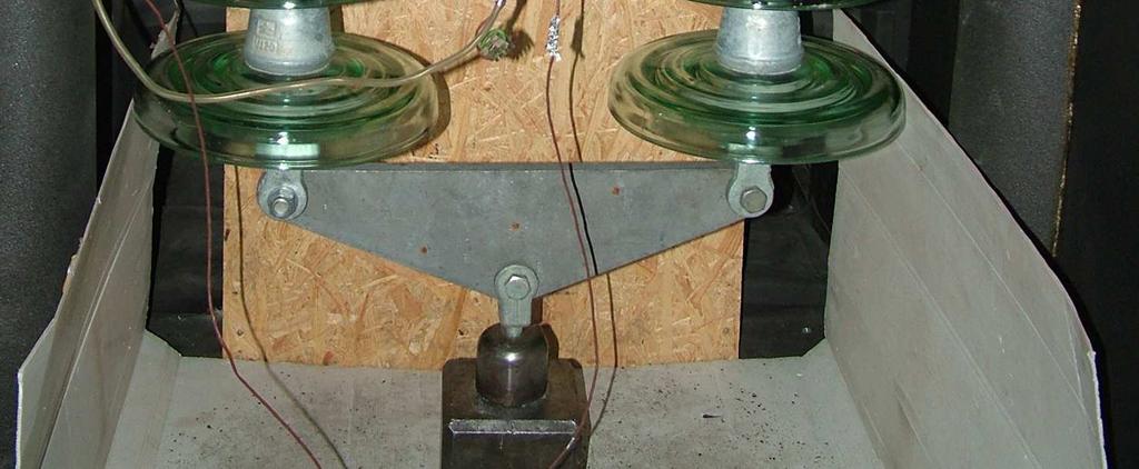
17 Page 17 of 29 III.4.Power arc test III.4.1 Test circumstances Three new insulator strings were subjected to power arc tests according to the IEC standard. One string consisted three cap and pin type glass insulator units. After one power arc test the string was replaced for a new one. The attached drawing is serving the identification of the tested insulator. The test arrangement can be seen on Figure 1. III.4.2 Test carried out The tests were carried out in single-phase test circuit supplied from 50 Hz network. Figure 2 shows the connection diagram of the test circuit. The insulator strings prepared for the power arc tests is shown on Photos The tests were performed on the insulator strings in the order indicated below: Name of the tests Figures, Photos, Diagrams Results 1. Power arc tests on insulator string (3 glass units / string) with Figure 1 parameters of 6 ka 0.2 s; 6 ka 0.2 s; 6 ka 0.2 s Photos Visual examination 3. Mechanical failing load tests were carried out on the tested strings according to the IEC 61467:2008 standard. (70% of - PASSED SML) 4. Checking of dimensions - PASSED PASSED (details in Table 12) During the tests oscillograms were taken. Arc current and arc voltage were registered by transient recorder with sampling rate of 50 µs and supplemented with the calculated arc power and energy. On the oscillograms and in the Figures enclosed to the test report the next notations are applied: U I P E arc voltage, arc current, arc power (created by mathematical way), arc energy (created by mathematical way). The measuring circuit is shown in Figure 2. The measuring equipment and devices used for the tests are listed on Page 21 as well as the uncertainty of the measurement of each electrical quantity on. III.4.3 Result of the tests During the power arc tests separation of cap and pin could not be observed. The tested cap and pin type porcelain insulator withstood the power arc test with parameters assigned by the manufacturer and passed the mechanical failing load tests with the prescribed load. The test circumstances, parameters and results are collected in Table 12. The tested glass insulators fulfilled the requirements of referred IEC standard.
18 Page 18 of 29 Figure 1 The test arrangement 1. Tested insulators 2. Ignition wire: Ø 0.63 mm (0.31 mm 2 ) copper 3. Insulating plate (800 x 800 mm) 4. Insulating cylinder (Ø 120 mm) 5. Auxiliary insulators (All dimension in millimetre)
19 Page 19 of 29
20 Page 20 of 29 Power arc test on cap and pin type glass insulators Test arrangement / test circuit: Figure 1 / 2 Supply and return conditions: D (Supply: unbalanced; Return: unbalanced) Cross-section of fusible wire: 0.31 mm 2 (copper) No. of the tested strings: Specified arc current (I n ) / arc time (t n ): 6 ka / 200 ms 6 ka / 200 ms 6 ka / 200 ms Oscillogram No.: BDK 1002 BDK 1003 BDK 1004 Arc current: peak value [ka]: r.m.s. value [ka]: Arc time [ms]: I t [kas]: Prescribed value with tolerance of + 10% Achieved value: Arc voltage [kv]: Arc power [MW]: Arc energy [MJ]: No-load voltage of the test circuit [kv]: Photos: High-speed film (2000fps): Atmospheric conditions: wind speed [m/s]: atmospheric pressure [hpa]: temperature [ C]: humidity [%]: rainfall: Remarks and results: - After the power arc test all tested insulator passed the mechanical failing load test with 70% of SML - Neither breakage of sheds nor separation could be observed after the tests. Table 12 Summary of test circumstances and results of the tests
21 Page 21 of 29 Uncertainty of measurements During the tests the uncertainties of the measurements were the following: mechanical load (Amsler): ± 1% mechanical load (WPM): ± 0.5 lightning impulse voltage: ± 0.5% power frequency voltage: ± 1% conductivity: ± 1% Uncertainty of the radio interference level measurement: ± 1dB Voltage measurement: ± 0.33% Current measurement: ± 0.33% The uncertainty values given in this report are the standard deviation values multiplied by k=2. Measurement uncertainty was estimated according to the method described in the EA-4/02 document. Measuring devices used for the tests: No. Designation Manufacturer Type S/N: [1] Tensile machine WPM ZD 10/90 263/1111/DS [2] Tensile machine AMSLER ZD /66/9 [3] Coating Thickness Meter LIST MAGNETIK 20-ST 20ST-1150 [4] Impulse generator MICAFIL SH B1698 [5] Divider VEIKI TA-1 01 [6] Impulse voltage TR-AS TR-AS 100- [7] Voltage divider TUR KDIS 350/ /1 [8] Termination TUR H [9] Indoor 50 Hz test TUR PEO [10] Peak voltmeter SIEMENS MU [11] Coupling capacitor MICAFIL TEPI-P800 77H734 [12] Radio interference meter SIEMENS B83600-B40 A [13] Impedance adaptor ( Ω) SIEMENS B83600-B56 A [14] VD 42 kv / 100 V VEIKI R-C-R 19 [15] Sh 20 ka VEIKI -- S20-5 [16] PSO 9070LS ECKELMANN PSO 9070LS


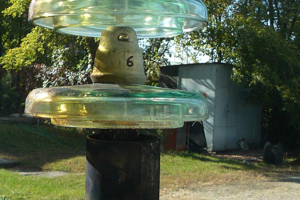
22 Page 22 of 29 PHOTOS Photo 1 The test arrangement of verification of the locking system Photo 2 The test arrangement of verification of the axial and radial displacements


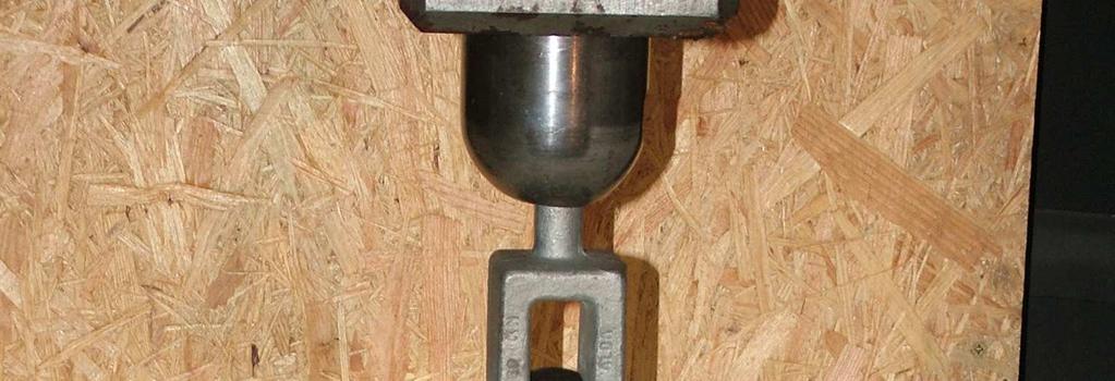
23 Page 23 of 29 Photo 3 The test arrangement of thermal-mechanical test Photo 4 The test arrangement of failing load tests


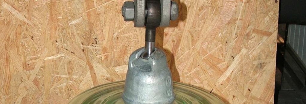
24 Page 24 of 29 Photo 5 The test arrangement of the residual test Photo 6 The broken insulators after the residual strength test


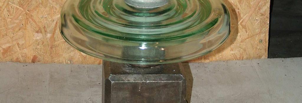
25 Page 25 of 29 Photo 7 The test arrangement of dielectric test on one unit insulator Photo 8 The test arrangement of dielectric test on short standard string


26 Page 26 of 29 Photo 9 The test arrangement of RIV measurement Photo 10 The test arrangement of the puncture test in air


27 Page 27 of 29 Photo 11 The test arrangement of power arc test Photo 12 The first insulator string prepared for the power arc test


28 Page 28 of 29 Photo 13 The first insulator string after the power arc test Photo 14 The second insulator string after the power arc test


29 Page 29 of 29 Photo 15 The third insulator string after the power arc test
CSA Design Test Report CS-8 Glass Bells Catalog # PCN160146
 CSA Design Test Report CS-8 Glass Bells Catalog # PCN160146 This design test report records the results of laboratory tests performed on the CS-8 Glass Bells which met or exceeded all performed tests of
SPECIFICATION SS 51/9 400KV COUPLING CAPACITORS FOR POWER LINE CARRIER SYSTEM
 INDEPENDENT POWER TRANSMISSION OPERATOR S.A. TNPRD/ SUBSTATION SPECIFICATION & EQUIPMENT SECTION January 2017 SPECIFICATION SS 51/9 400KV COUPLING CAPACITORS FOR POWER LINE CARRIER SYSTEM I. SCOPE This
TYPE. max. working voltage 250 V 350 V 500 V 750 V. max. overload voltage 500 V 700 V 1000 V 1500 V. basic specifications IEC B
 FEATURES Non inductive High pulse loading capability. APPLICATIONS Application for overload and high voltage surge hazard circuits. DESCRIPTION A carbon film is deposited on a high grade ceramic body.
FEATURES APPLICATIONS DESCRIPTION QUICK REFERENCE DATA. PILKOR components
 FEATURES Excellent anti-surge characteristics Stable characteristics to moisture resistance even in high resistance range. Good replacement for ceramic plate resistors. APPLICATIONS Telecommunication Industrial
Interference suppression film capacitors MKP 336 1
 MKP RADIAL POTTED TYPE PITCH /15/22.5/27.5 mm l b h lt P d t CBA196 Fig.1 Simplified outlines. FEATURES to 27.5 mm lead pitch Supplied loose in box and taped on reel Consists of a low-inductive wound cell
Metallized polyester film capacitors MKT 470
 MKT RADIAL POTTED TYPE PITCH 5 mm CBA141 Fig.1 Simplified outlines. FEATURES Low-inductive wound cell of metallized (PETP) film Potted with epoxy resin in a flame-retardant case Radial leads of solder-coated
O Plus Dry Bushing 69 kv system, 350 kv BIL, 3000 A. Table of contents
 Type test report O Plus Dry Bushing 69 kv system, 0 kv BIL, 000 A Table of contents Abstract... 2 2 Certification... 2 Introduction.... Description and ratings....2 Overview of tests.... Applicable standards....4
Metallized Polypropylene Film Capacitor DC-Link Capacitor MKP Type
 Metallized Polypropylene Film Capacitor DC-Link Capacitor MKP Type FEATURES Slim line, low building height Very long useful life time: Up to 100 000 h at U NDC and 70 C High ripple current capability,
DC Film Capacitors MKT Axial Type
 MKT181 DC Film Capacitors MKT Axial Type FEATURES Supplied loose in box, taped on ammopack or reel Material categorization: For definitions of compliance please see www.vishay.com/doc?9991 APPLICATIONS
O Plus Dry Bushing 25 kv system, 150 kv BIL, 3000 A
 TYPE TEST REPORT O Plus Dry Bushing 25 kv system, 150 kv BIL, 3000 A 02 1 Abstract 02 2 Certification 03 3 Introduction 03 3.1 Description and ratings 03 3.2 Overview of tests 03 3.3 Applicable standards
Film Capacitors. EMI suppression capacitors. Date: June 2018
 Film Capacitors EMI suppression capacitors Date: June 2018 EPCOS AG 2018. Reproduction, publication and dissemination of this publication, enclosures hereto and the information contained therein without
High-ohmic/high-voltage resistors
 FEATURES These resistors meet the safety requirements of: UL1676 (range 510 kω to 11 MΩ) EN60065 BS60065 (U.K.) NFC 92-130 (France) VDE 0860 (Germany) High pulse loading capability Small size. APPLICATIONS
Snubber MMKP 386 AC and pulse double metallized film capacitor
 Page 1 of 19 VISHAY BCcomponents Snubber MMKP 386 AC and pulse double metallized film capacitor File under TPD sheet 190, HQN-384-17/110 Page 2 of 19 Pb AC and Pulse Double Metallized polypropylene MMKP
AC and Pulse Metallized Polypropylene Film Capacitors MKP Axial Type
 Vishay Roederstein AC and Pulse Metallized Polypropylene Film Capacitors FEATURES Supplied loose in box, taped on ammopack or reel available on request l t APPLICATIONS High current and high pulse operations
S P E C I F I C A T I O N S
 TO : 2009-09-14 S P E C I F I C A T I O N S PRODUCT : CERAMIC CAPACITOR MODEL : DA (X1,Y1) SERIES Manufacturer Customer WRITTEN CHECKED APPROVED WRITTEN CHECKED APPROVED 9/14 9/14 9/14 / / / DONG IL ELECTRONICS
MKP-X2 TECHNICAL TERMS EXPLANATION
 TECHNICAL TERMS EXPLANATION Rated capacitance Capacitance referred to 1 khz, 20 +-1ºC, 65+-2% of relative humidity and 96+- 10 kpa. In case of doubt please refer to IEC 60068-1, sub-clause 5.2. Capacitance
AC and Pulse Double Metallized Polypropylene Film Capacitors MMKP Radial Potted Type
 AC and Pulse Double Metallized Polypropylene Film Capacitors MMKP Radial Potted Type FEATURES 7.5 mm to 37.5 mm lead pitch; 7.5 mm bent back pitch Low contact resistance Low loss dielectric Small dimensions
This specification covers the requirements for product performance, test methods and quality assurance provisions of FG Terminal.
 DESIGN OBJECTIVES The product described in this document has not been fully tested to ensure conformance to the requirements outlined below. Therefore AMP Ltd makes no representation or warranty, express
IEC Type Test Report Report No. EU1527-H-00.1 PH3 Series Polymer-housed Arrester 10,000 A Line Discharge Class 3
 EU1527-H-00.1 IEC Type Test Report Report No. EU1527-H-00.1 PH3 Series Polymer-housed Arrester 10,000 A Line Discharge Class 3 This report records the results of type tests made on PH3 series 10 ka Line
Electrical, Electronic and Computer Engineering ENEL4HB - High Voltage 2
 Electrical, Electronic and Computer Engineering ENEL4HB - High Voltage 2 Main Examination October 2015 Instructions Answer all questions and show all working. Time allowed = 2 hours Full marks = 100 Question
Characteristics and Definitions Used for Film Capacitors
 Characteristics and Definitions Used for Film Capacitors COMMON FILM DIELECTRICS USED IN FILM CAPACITORS PRODUCTS PARAMETER DIELECTRIC (1) UNIT Dielectric constant 1 khz 3.3 3 3. - Dissipation factor 1
DC Film Capacitors MKT Radial Lacquered Type
 DC Film Capacitors MKT Radial Lacquered Type FEATURES Available taped and loose in box Material categorization: for definitions of compliance please see www.vishay.com/doc?99912 APPLICATIONS Blocking and
High Ohmic/High Voltage Resistors
 High Ohmic/High Voltage Resistors VR68 A metal glazed film is deposited on a high grade ceramic body. After a helical groove has been cut in the resistive layer, tinned electrolytic copper wires are welded
RS INDUSTRY LIMITED. RS Chip Array ESD Suppressor APPROVAL SHEET. Customer Information. Part No. : Model No. : COMPANY PURCHASE R&D
 APPROVAL SHEET Customer Information Customer : Part Name : Part No. : Model No. : COMPANY PURCHASE R&D Vendor Information Name: RS INDUSTRY LIMITED Part Name ARRAY TYPE MULTILAYER VARISTOR Part No. RS
Power System Engineering Prof. Debrapriya Das Department of Electrical Engineering Indian Institute of Technology, Kharagpur
 Power System Engineering Prof. Debrapriya Das Department of Electrical Engineering Indian Institute of Technology, Kharagpur Lecture - 01 Overhead Line Insulators So, welcome to this another course that
Damping resistor design consideration
 http : //www.cigre.org CIGRÉ B4-054 CIGRÉ Winnipeg 2017 Colloquium Study Committees A3, B4 & D1 Winnipeg, Canada September 30 October 6, 201717 Damping resistor design consideration Elassad Yann MS Resistances
TYPE. 250 ppm / 200 ppm /
 FEATURES High power in small packages Available wide range to automatic insertion machine. APPLICATIONS All general purpose power applications. DESCRIPTION A homogeneous film of metal alloy is deposited
Metallized Polyester Film Capacitors MKT Radial Potted Types
 www.vishay.com Metallized Polyester Film Capacitors MKT Radial Potted Types FEATURES Material categorization: for definitions of compliance please see www.vishay.com/doc?99912 APPLICATIONS Blocking, bypassing,
AC Line Rated Ceramic Disc Capacitors Class X1, 760 V AC, Class Y1, 500 V AC
 AC Line Rated Ceramic Disc Capacitors Class X1, 760 V AC, Class Y1, 500 V AC FEATURES Complying with IEC 60384-14 4 th edition Can pass 10 kv pulses (10 per polarity) Withstands 85 / 85 / 1000 h test Reduced
Metallized Polyester Film Capacitors MKT Radial Potted Type
 www.vishay.com Metallized Polyester Film Capacitors MKT Radial Potted Type FEATURES 7.5 mm lead pitch Supplied loose in box and taped on reel or ammopack Material categorization: for definitions of compliance
VEIKI-VNL ELECTRIC LARGE LABORATORIES Ltd. TYPE TEST REPORT
 Page 1 of 13 TYPE TEST REPORT Test object: Designation: All Aluminium Alloy Conductor (AAAC) 50 mm 2 All Aluminium Alloy Conductor (Code: 49-AL3) Manufacturer: BMET Energy Telecom Industry and Trade LLC.
DC Film Capacitors MKT Radial Potted Type
 DC Film Capacitors MKT Radial Potted Type FEATURES 15 mm to 27.5 mm lead pitch. Supplied loose in box and taped on reel Material categorization: for definitions of compliance please see www.vishay.com/doc?99912
High Ohmic/High Voltage Resistors
 High Ohmic/High Voltage Resistors A metal glazed film is deposited on a high grade ceramic body. After a helical groove has been cut in the resistive layer, tinned electrolytic copper wires are welded
PFC Input Capacitors PCMP 472 Metallized Polypropylene film capacitors
 MKP RADIAL LACQUERED CAPACITORS(Dipped Type)-Brown Pitch 10.0/15.0/22.5/27.5mm (reduced pitch 7.5mm) QUICK REFERENCE DATA Capacitance range (E6 series) Capacitance tolerance Rated voltage (DC) Climatic
AC and Pulse Double Metallized Polypropylene Film Capacitors MMKP Radial Potted Type
 AC and Pulse Double Metallized Polypropylene Film Capacitors MMKP Radial Potted Type FEATURES 7.5 mm to 37.5 mm lead pitch Material categorization: for definitions of compliance please see /doc?99912 APPLICATIONS
Suppressor film capacitor Highlight and Application in Series with the main
 Suppressor film capacitor Highlight and Application in Series with the main April 2007 Paola Bettacchi - Product Manager 1 Film capacitor : main features and performances Process flow charts Self-healing
THB AC Filtering Metalized Polypropylene Film Capacitor Radial Type 85 C / 85 % RH 1000 h at U NAC
 THB AC Filtering Metalized Polypropylene Film Capacitor Radial Type 85 C / 85 % RH 00 h at U NAC FEATURES High robustness under high humidity THB 85 C, 85 % RH, 00 h at rated U NAC UL 8 (electrical pending)
High-Voltage Types Ordering Information, Mica Capacitors
 High-Voltage Types Ordering Information, Mica Capacitors Ordering Information Ordering Information: Order by complete part number, as below. For other options,write your requirements on your quote request
FILM DIELECTRICS USED IN FILM CAPACITOR PRODUCTS
 FILM DIELECTRICS USED IN FILM CAPACITOR PRODUCTS Overview PARAMETER Dielectric constant: DIELECTRIC (1) KT KN KI KP UNIT at 1 khz 3.3 3.0 3.0. Dissipation factor at 1 khz 50 40 3 1 10-4 at 10 khz 110 6
DC Film Capacitors MKT Radial Potted Type
 DC Film Capacitors MKT Radial Potted Type MKT80 FEATURES AEC-Q00 qualified (rev. D) for PCM. mm (for larger available components on request) High temperature capabilities, up to 0 C Capacitance up to 60
HIGH VOLTAGE MULTILAYER CERAMIC CAPACITORS
 DESCRIPTION: RoHS compliant (*) Capacitors 0805 to 6560 Rated voltage 1000V to 10KV Dielectric Type I and II SMD and leaded versions * Non RoHS version still maintained for current applications. I. Foreword
High Ohmic/High Voltage Metal Glaze Leaded Resistors
 High Ohmic/High Voltage FEATURES A metal glazed film is deposited on a high grade ceramic body. After a helical groove has been cut in the resistive layer, tinned electrolytic copper wires are welded to
Specifications: The shelf life of product is within 6 months. Features Description Test Conditions Requirements
 Specifications: Operating Temperature Range : -25 C to+70 C Storage Temperature Range : -30 C to +80 C Current Range : 50mA, 12V DC The shelf life of product is within 6 months Test Sequence: Appearance
Electrical, Electronic and Computer Engineering ENEL4HB - High Voltage 2
 Electrical, Electronic and Computer Engineering ENEL4HB - High oltage 2 Main Examination October 2016 Instructions Answer all questions, show all working and include all necessary comments (it is your
Fatima Michael College of Engineering & Technology
 ANNA UNIVERSITY AFFILIATED COLLEGES BE EEE SEMESTER VI EE2353 - HIGH VOLTAGE ENGINEERING UNIT IOVER VOLTAGES IN ELECTRICAL POWER SYSTEMS 1. What is surge arrester? 2. Name the sources of switching surges.
AC and Pulse PCMP 389 Metallized Polypropylene film capacitors
 MKP RADIAL POTTED CAPACITORS Pitch 10.0/15.0/22.5/27.5mm (reduced pitch 7.5mm) QUICK REFERENCE DATA Capacitance range (E24 series) Capacitance tolerance Rated voltage (DC) Climatic category Temperature
1W, 1206, Low Resistance Chip Resistor (Lead free / Halogen Free)
") 1W, 1206, (Lead free / Halogen Free) 1. Scope This specification applies to 1.6mm x 3.2mm size 1W, fixed metal film chip resistors rectangular type for use in electronic equipment. 2. Type Designation
1W, 1206, (Lead free / Halogen Free) 1. Scope This specification applies to 1.6mm x 3.2mm size 1W, fixed metal film chip resistors rectangular type for use in electronic equipment. 2. Type Designation
Code No: RR Set No. 1
 Code No: RR410209 Set No. 1 1. What are the gases mainly used in insulating medium at high pressures? Which is more suitable? Why? What about its dielectric strength? Explain. [16] 2. (a) Define time lags
Independent, accredited testing station Member laboratory of STL and LOVAG TEST CONFIRMATION. on the given range of performed tests
 Independent, accredited testing station Member laboratory of STL and LOVAG TEST CONFIRMATION on the given range of performed tests 3M Laboratories Europe Zweigniederlassung der 3M Deutschland GmbH Carl-Schurz-Str.
DC Film Capacitors MKT Radial Lacquered Type
 l 467 w FEATURES Available taped and loose in box RoHS compliant Seating plane (1) h APPLICATIONS Blocking and coupling, bypass and energy reservoir. α (2) l t REFERENCE STANDARDS IEC 60384-2 MARKING C-value;
INSTITUTE OF AERONAUTICAL ENGINERING DUNDIGAL ELECTRICAL AND ELECTRONICS ENGINEERING
 INSTITUTE OF AERONAUTICAL ENGINERING DUNDIGAL ELECTRICAL AND ELECTRONICS ENGINEERING Course code : 5067(07-08) Course title : High voltage engineering Course structure Lectures Tutorials Practical credits
EMI Suppression PCRC 420 film capacitors (RC unit)
") MKP RADIAL POTTED CAPACITORS Pitch 15.0/17.5 mm P = 15.0 / 17.5mm QUICK REFERENCE DATA Capacitance value Capacitance tolerance Resistance value Resistance tolerance Rated (AC) voltage 50 to 60 Hz Climatic
MKP RADIAL POTTED CAPACITORS Pitch 15.0/17.5 mm P = 15.0 / 17.5mm QUICK REFERENCE DATA Capacitance value Capacitance tolerance Resistance value Resistance tolerance Rated (AC) voltage 50 to 60 Hz Climatic
High-voltage Ceramic Capacitors (DC250V-6.3kV)
") High-voltage Ceramic Capacitors (DC250V-6.kV) DEB Series (Class 2/DC1k-.15kV) Features 1. Small size and high capacitance. 2. Coated with flame-retardant epoxy resin. (equivalent to UL94V-0
High-voltage Ceramic Capacitors (DC250V-6.kV) DEB Series (Class 2/DC1k-.15kV) Features 1. Small size and high capacitance. 2. Coated with flame-retardant epoxy resin. (equivalent to UL94V-0
ZNR Transient/Surge Absorbers (Type E)
") ZNR Transient/Surge Absorbers Type : E The ZNR Type E is capable of handling larger surge energy than Type D in applications to protect electronic equipment or semiconductor devices from switching and
ZNR Transient/Surge Absorbers Type : E The ZNR Type E is capable of handling larger surge energy than Type D in applications to protect electronic equipment or semiconductor devices from switching and
Product Data Sheet PD-0037-B
 Product Data Sheet PD-0037-B 3M Shielded Compact Ribbon (SCR) Connector 3M Shielded Compact Ribbon (SCR) Boardmount Right Angle 36110-2220 XX 3 Electronic Solutions Division Page: 1 of 12 Table of Contents
OR Explain thermal breakdown in solid dielectrics. How this mechanism is
 Subject : High Voltage Engineering (2090) ITM Universe, Vadodara Electrical Engineering Department Class : Electrical Sem : th Long Questions Sr. No Question Unit No : 0 Explain Charge Simulation method
FEATURES Overload protection without risk of fire wide range of overload currents. APPLICATIONS TV, Monitor, Audio, Video DESCRIPTION
 FEATURES Overload protection without risk of fire wide range of overload currents. APPLICATIONS TV, Monitor, Audio, Video DESCRIPTION A homogeneous film of metal alloy is Deposited on a high grade ceramic
For the electronic measurement of current: DC, AC, pulsed..., with galvanic separation between the primary and the secondary circuit.
 Current Transducer LDSR 0.3-TP/SP1 I P R N = 300 ma For the electronic measurement of current: DC, AC, pulsed..., with galvanic separation between the primary and the secondary circuit. Features Closed
Blower Motor 3P Connector
 1. Scope Blower Motor P Connector 1.1 Content This specification covers the requirements for product performance, test methods and quality assurance provisions of Blower Motor P connector. Applicable product
Issued August DATA SHEET. 3VT3 MCCB up to 630 A
 ssued August 9 DATA SHEET VT MCCB up to 6 A Based on Siemens Catalog V 6 8 Circuit breakers Switch disconnectors Technical specifications Specifications Type VT 76-AA6/6/56-AA, VT 76-AA6/6/56-AA Circuit
PFC Input Capacitors PCMP 372 Metallized Polypropylene film capacitors
 MKP RADIAL POTTED CAPACITORS Pitch 10.0/15.0/22.5/27.5mm QUICK REFERENCE DATA Capacitance range (E6 series) Capacitance tolerance Rated voltage (DC) Climatic category Temperature range Reference specification
TYPE. 250 ppm / 200 ppm / rated dissipation at T amb = ppm / 200 ppm / 250 ppm / 200 ppm /
 FEATURES Overload protection without risk of fire wide range of overload currents. APPLICATIONS TV, Monitor, Audio, Video DESCRIPTION A homogeneous film of metal alloy is Deposited on a high grade ceramic
- CAUTION AND WARNING -
 - CAUTION AND WARNING - Please contact us for complete technical specification before use and confirm the appropriate condition of your application. If used in a specific appliance that requires an extremely
3/4W, 2010 Low Resistance Chip Resistor
 1. Scope 3/4W, 2010 This specification applies to 2.5mm x 5.0mm size 3/4W, fixed metal film chip resistors rectangular type for use in electronic equipment. 2. Type Designation RL2550 L - Where (1) (2)
INSTITUTE OF AERONAUTICAL ENGINEERING (Autonomous) Dundigal, Hyderabad
 Dundigal, Hyderabad") INSTITUTE OF AERONAUTICAL ENGINEERING (Autonomous) Dundigal, Hyderabad - 00 0 Department of Electrical and Electronics Engineering TUTORIAL QUESTION BANK Course Name : HIGH VOLTAGE ENGINEERING Course Code
INSTITUTE OF AERONAUTICAL ENGINEERING (Autonomous) Dundigal, Hyderabad - 00 0 Department of Electrical and Electronics Engineering TUTORIAL QUESTION BANK Course Name : HIGH VOLTAGE ENGINEERING Course Code
PRODUCT SPECIFICATIONS
 PRODUCT SCIFICATIONS CUSTOMER : CUSTOMER'S REFERENCE : 3/34 3/35 3/36 Series DESCRIPTIONS : SHENGXIN TY : METALLIZED POLYESTER FILM CAPACITOR-BOX series Fig. w T T W H.5max P 20min H S L0.5max Fig Fig2.
WIESON TECHNOLOGIES CO., LTD.
 TABLE OF CONTENT 1. Scope.... 2 2. Reference Documents. 2 3. Material and Components.... 2 4. Design and Construction.... 2 5. Rating.. 2 6. Performance and Test Descriptions. 2 7. Test Requirements and
FIXED THICK FILM CHIP RESISTORS; RECTANGULAR TYPE & HIGH OHM. RoHS COMPLIANCE ITEM Halogen and Antimony Free
 Spec. No.: RHC K HTS 0001 /8 Date: 2017. 1. 10 Specification Title: FIXED THICK FILM CHIP RESISTORS; RECTANGULAR TYPE & HIGH OHM Style:,20 RoHS COMPLIANCE ITEM Halogen and Antimony Free Product specification
Issued August DATA SHEET. 3VT5 MCCB up to 1600 A
 ssued August 9 DATA SHEET VT5 MCCB up to 0 A Based on Siemens Catalog V 8 Standard circuit breakers Releases Technical specifications Specifications VT5 circuit breakers Switch disconnectors Type Standards
TEST REPORT RP
 Page 1 of 36 Environmental and material tests (ENV) SECTOR Product description: Tested Models: Manufacturer: Led lights Sample 01 -> Led Puma -> 28234/LED/AS Sample 02 -> Extreme Led -> 556600_04 Sample
AC and Pulse Metallized Polypropylene Film Capacitors MKP Radial Potted Type
 AC and Pulse Metallized Polypropylene Film Capacitors MKP Radial Potted Type FEATURES 5 mm to 37.5 mm lead pitch Material categorization: for definitions of compliance please see www.vishay.com/doc?9992
Metallized Polypropylene film capacitor PCMP 371
 MKP RADIAL POTTED CAPACITORS Pitch 22.5/27.5 mm QUICK REFERENCE DATA Capacitance range Capacitance tolerance Rated voltage (AC) Rated Frequency Climatic category Temperature range Reference specification
CL - High Power, High Q, NP0, RoHS
 DSCRIPTION Low SR/SL NP0 Porcelain Capacitors xcellent characteristics in current, voltage and power with high Q factor Highest working voltage in class 7 000V APPLICATIONS RF Power Amplifiers Industrial
DEPARTMENT OF ELECTRICAL AND ELECTRONICS ENGINEERING QUESTION BANK
 DEPARTMENT OF ELECTRICAL AND ELECTRONICS ENGINEERING QUESTION BANK SUBJECT CODE & NAME: EE 2303 - TRANSMISSION & DISTRIBUTION YEAR / SEM: III/V UNIT-I TRANSMISSION SYSTEM INTRODUCTION PART-A 1. What is
CR-PF Series Ultra-Low Lead Content Thick Film Resistor
 RoHS COMPLIANT** & HALOGEN FREE*** 102 Features n Ultra-low lead (Pb) content* n Green technology n High reliability and stability n Thick film paste on high grade ceramic substrate n RoHS compliant**
TECHNICAL INFORMATION
 TECHNICAL INFORMATION RATED PRIMARY OLTAGE () This is the supply assigned to the transformer by the manufacturer. RATED SECONDARY OLTAGE () This is the secondary output assigned to the transformer when
DATA SHEET SURFACE-MOUNT CERAMIC MULTILAYER CAPACITORS General purpose & High capacitance Class 2, X5R
 DATA SHEET SURFACE-MOUNT CERAMIC MULTILAYER CAPACITORS General purpose & High capacitance Class 2, 6.3 V TO 50 V 10 nf to 100 µf RoHS compliant Product Specification Product specification 2 Surface-Mount
Capacitors. Typical electrical characteristics of metallized polyester capacitors KEU. Type KEU Metallized polyester capacitors
 Capacitors Type KEU Metallized polyester capacitors As a dielectric high quality polyester film with good electrical properties is used. Electrodes of capacitor are vacuum metallized aluminium. The thickness
Chip Inductors. LCCM Series Chip Common Mode Filter FEATURES CONSTRUCTION
 FEATURES Small wire wound chip inductor with ferrite core and 2 common mode lines. Highly effective in noise suppression High common-mode impedance at noise band an low differential mode impedance at signal
Digital Current Transducer HO-SW series I P N = A. Ref: HO 100-SW; HO 150-SW; HO 200-SW; HO 250-SW
 Digital Current Transducer HO-SW series I P N = 100... 250 A Ref: HO 100-SW; HO 150-SW; HO 200-SW; HO 250-SW Bitstream output from on onboard Sigma Delta modulator. For the electronic measurement of current:
M I N I S T R Y O F C O M M U N I C A T I O N S T E L E C O M M U N I C A T I O N S S E C T O R T E C H N I C A L S T A N D A R D F O R
 M I N I S T R Y O F C O M M U N I C A T I O N S T E L E C O M M U N I C A T I O N S S E C T O R T E C H N I C A L S T A N D A R D F O R M A T E R I A L S N O. G 2 0 : 1 0 : 0 0 1 : 1 8 J U M P E R W I
INSTITUTE OF AERONAUTICAL ENGINERING DUNDIGAL ELECTRICAL AND ELECTRONICS ENGINEERING
 INSTITUTE OF AERONAUTICAL ENGINERING DUNDIGAL ELECTRICAL AND ELECTRONICS ENGINEERING Course code : 067(07-08) Course title : High voltage engineering Course structure Lectures Tutorials Practical credits
Modeling of Transmission Line and Substation for Insulation Coordination Studies
 TRAINING DUBROVNIK, CROATIA - APRIL, 27-29 2009 SIMULATION & ANALYSIS OF POWER SYSTEM TRANSIENTS WITH EMTP-RV Modeling of Transmission Line and Substation for Insulation Coordination Studies Prof. Ivo
DATA SHEET SURFACE-MOUNT CERAMIC MULTILAYER CAPACITORS General purpose & High capacitance Class 2, X5R
 DATA SHEET SURFACE-MOUNT CERAMIC MULTILAYER CAPACITORS General purpose & High capacitance Class 2, 6.3 V TO 50 V 10 nf to 100 µf RoHS compliant Product Specification Product specification 2 Surface-Mount
Cap. pf R R R R Rated WVDC 2.2 2R R R A,B, 0.5 0R5 3.
 0201N (.020" x.010") 0201N Capacitance & Rated Voltage Table Cap. pf 0.1 0R1 Tol. Rated WVDC Cap. pf 2.2 2R2 Remark: special capacitance, tolerance and WVDC are available, consult with PASSIVE PLUS. Tol.
DC Film Capacitors MKT Radial Potted Type
 DC Film Capacitors MKT Radial Potted Type FEATURES 7.62 mm lead pitch. Supplied loose in box and taped on reel or ammopack AEC-Q200 qualified Material categorization: For definitions of compliance please
DATA SHEET SURFACE-MOUNT CERAMIC MULTILAYER CAPACITORS C-Array: Class 2, X7R 16/25/50 V size 0612 (4 0603) Product Specification Jul 21, 2003 V.
 Product Specification Jul 21, 2003 V.") DATA SHEET SURFACE-MOUNT CERAMIC MULTILAYER CAPACITORS C-Array: Class 2, X7R 16/25/50 V Product Specification Jul 21, 2003 V.6 FEATURES 0612 (4 0603) capacitors (of the same capacitance value) per array
DATA SHEET SURFACE-MOUNT CERAMIC MULTILAYER CAPACITORS C-Array: Class 2, X7R 16/25/50 V Product Specification Jul 21, 2003 V.6 FEATURES 0612 (4 0603) capacitors (of the same capacitance value) per array
Metallized Polyester PCMT 369 film capacitors
 MKT RADIAL LACQUERED CAPACITORS (Dipped Type) Pitch 10.0/15.0/22.5/27.5 mm (reduced pitch ; 7.5mm) QUICK REFERENCE DATA Capacitance range (E12 series) Capacitance tolerance Rated voltage V Rdc Climatic
MKV AC Capacitors Damping B High dielectric strength High peak-current capability Especially suitable for snubber circuits
 MKV AC Capacitors B 25 835 High dielectric strength High peak-current capability Especially suitable for snubber circuits Construction Self-healing Plastic dielectric Oil-impregnated tubular windings (no
DATA SHEET SURFACE-MOUNT CERAMIC MULTILAYER CAPACITORS NP0/X5R/X7R
 Product Specification May 5, 2017 V.10 DATA SHEET SURFACE-MOUNT CERAMIC MULTILAYER CAPACITORS 01005 NP0/X5R/X7R 4 V TO 25 V 0.5 pf to 470 nf RoHS compliant & Halogen Free 2 SCOPE This specification describes
Qualification Test Report
 Qualification Test Report 501-97 28Jun10 Rev E Connector, Shielded, Miniature Circular DIN, PCB Mounted 1. INTRODUCTION 1.1. Purpose Testing was performed on Tyco Electronics Mini DIN Printed Circuit Board
WK25V, WK20V, WK12V, WK08V, WK06V. Thick Film High Voltage Chip Resistors. Size 2512, 2010,1206, 0805, 0603
 WK25V, WK20V, WK12V, WK08V, WK06V ±5%, ±2%, ±1%, ±0.5% Thick Film High Voltage Chip Resistors Size 2512, 2010,1206, 0805, 0603 *Contents in this sheet are subject to change without prior notice. Page 1
Fusible Resistors Ambient Temperature ( )
") Fusible Resistors RATING: C.1 Rated power is the value of max. load voltage specified at the ambient temperature of 70. When the ambient temperature surpasses the above mentioned temperature, the value
Fusible Resistors RATING: C.1 Rated power is the value of max. load voltage specified at the ambient temperature of 70. When the ambient temperature surpasses the above mentioned temperature, the value
DC Film Capacitors MKT Axial Type
 MKT 181 Ø d FEATURES Supplied loose in box, taped on ammopack or reel RoHS compliant L 40.0 ±.0 40.0 ±.0 Max. Dimensions in mm D Max. ENCAPSULATION Plastic-wrapped, epoxy resin sealed, flame retardant
Precision Leaded Resistors
 FEATURES Approved according to CECC 40101-806 Advanced thin film technology Low TC: ± 15 to Precision tolerance of value: ± 0.1 % and ± 0.25 % Superior overall : class 0.05 Wide precision range: 10 to
 Anna University B.E/B.Tech Degree Examination November/December 2010, Seventh Semester, Electrical and Electronics Engineering, EE1402-HIGH VOLTAGE ENGINEERING Answer all the questions. Part-A (10*2=20)
2W, 2816, SL Type Low Resistance Chip Resistor (Lead / Halogen Free)
") 2W, 2816, SL Type (Lead / Halogen Free) 1. Scope This specification applies to 4.2mm x 7.1mm size 2W, fixed metal foil current sensing resistors used in electronic equipment. 2. Features / Applications
2W, 2816, SL Type (Lead / Halogen Free) 1. Scope This specification applies to 4.2mm x 7.1mm size 2W, fixed metal foil current sensing resistors used in electronic equipment. 2. Features / Applications
Ref: HLSR 16-PW; HLSR 32-PW; HLSR 40-PW-000; HLSR 50-PW-000,
 Digital Current Transducer HLSR-PW series I P N = 16... 50 A Ref: HLSR 16-PW; HLSR 32-PW; HLSR 40-PW-000; HLSR 50-PW-000, Bitstream output from on onboard Sigma Delta modulator. For the electronic measurement
Standard Metal Film Leaded Resistors
 Standard Metal Film Leaded Resistors A homogeneous film of metal alloy is deposited on a high grade ceramic body. After a helical groove has been cut in the resistive layer, tinned connecting leads of
Conventional Paper-I-2011 PART-A
 Conventional Paper-I-0 PART-A.a Give five properties of static magnetic field intensity. What are the different methods by which it can be calculated? Write a Maxwell s equation relating this in integral