Test Report issued under the responsibility of: SHA-001 Date of issue... : Total number of pages... : 292. Report Number...
|
|
|
- Steven Fields
- 6 years ago
- Views:
Transcription

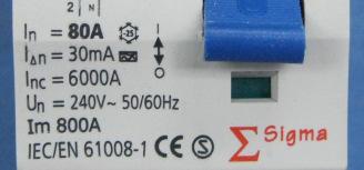
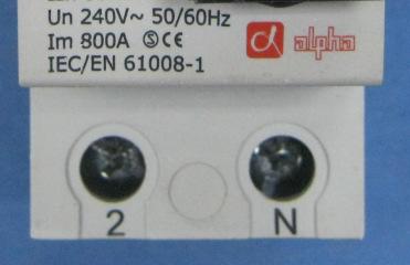
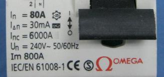
1 D Test Report issued under the responsibility of: TEST REORT Residual current operated circuit-breakers without integral overcurrent protection for household and similar uses (RCCBs) art 1: General rules Report Number.... : SHA-001 Date of issue... : Total number of pages... : 292 Applicant s name... : ZHEJIANG MAXGE ELECTRIC TECHNOLOGY CO., LTD. Address... : No.299 East Changhong Road, Deqing Economic zone, Wukang, Deqing, ZHEJIANG, CHINA Test specification: Standard... : :2010 (Third Edition) +A1:2012 used in conjunction with IEC :1990 (First Edition) Test procedure... : CB, S Non-standard test method..: EN :2012 Test Report Form No.... : IEC61008_1F Test Report Form(s) Originator... : OVE Master TRF... : Dated Copyright 2012 Worldwide System for Conformity Testing and Certification of Electrotechnical Equipment and Components (IECEE), Geneva, Switzerland. All rights reserved. This publication may be reproduced in whole or in part for non-commercial purposes as long as the IECEE is acknowledged as copyright owner and source of the material. IECEE takes no responsibility for and will not assume liability for damages resulting from the reader's interpretation of the reproduced material due to its placement and context. If this Test Report Form is used by non-iecee members, the IECEE/IEC logo and the reference to the CB Scheme procedure shall be removed. This report is not valid as a CB Test Report unless signed by an approved CB Testing Laboratory and appended to a CB Test Certificate issued by an NCB in accordance with IECEE 02. Test item description... : RCCBs Trade Mark... : Manufacturer... : Same as applicant Model/Type reference... : SGR, ER, ALR (See page 7 General product information) Ratings... : Un= 240V~(1+N), In=16, 20, 25, 32, 40, 50, 63, 80A; Type A and AC(30mA, 100mA, 300mA) for 16A to 80A; Type A and AC(10mA) for 16A to 25A; I c = Inc=6000A&10000A
2
3 age 3 of 292 Report No SHA-001 Summary of testing: Clause Testing items Testing location 6 Marking and other product information CBTL General CBTL Mechanism CBTL Clearances and creepage distances CBTL Non-interchangeability CBTL 9.3 Test of Indelibility of marking CBTL 9.4 Test of reliability of screws, current-carrying parts and connections. CBTL 9.5 Reliability of terminals for external conductors CBTL 9.6 Test of protection against electric shock CBTL 9.7 Test of dielectric properties Resistance to humidity CBTL Insulation resistance of the main circuit CBTL 9.7.3~9.7.7 Dielectric strength CBTL 9.8 Test of temperature-rise CBTL 9.9 Operating characteristic ACTL 9.10 Mechanical and electrical endurance ACTL 9.11 Behavior of the RCCBs under short circuit conditions ACTL 9.12 Resistance to mechanical shock and impact Mechanical shock CBTL Mechanical impact CBTL 9.13 Resistance to heat CBTL 9.14 Resistance to abnormal heat and to fire CBTL 9.15 Trip-free mechanism CBTL 9.16 Operation of the test device at the limits of rated voltage CBTL Behaviour of RCCBs in case of failure of the line voltage, classified according to Limiting values of the non-operating current under over current conditions CBTL ACTL 9.19 Resistance against unwanted tripping due to current surges ACTL 9.20 Resistance of the insulation against an impulse voltages ACTL Reliability Behaviour of RCCBs in case of an earth fault current comprising a d.c. components ACTL Climatic test CBTL
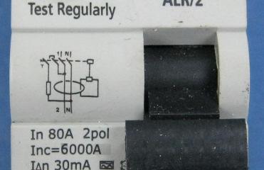
4 age 4 of 292 Report No SHA Test with temperature of 40 ACTL 9.23 Ageing of electronic components ACTL 9.24 Electromagnetic compatibility (EMC) CBTL Summary of compliance with National Differences The test results obtained and the general performance is considered to comply with the group differences of EN :2012. Summary of testing: Report ref.no SHA- 001 No. of poles I n (A) I n (A) Type Test sequence and number of samples A B C D 0 +D 1 D 2 E F G H a) EMC b) 1+N 80 0,03 A x x x x x x x x N 80 0,03 AC x N 80 0,1 A x N 80 0,3 A x N 80 0,1 AC x N 80 0,3 AC x N 25 0,01 A x x x x x x x x N 25 0,01 AC x N 16 0,3 A x x SHA N 80 0,03 A x x x x x x x x x x 3+N 80 0,03 AC x N 80 0,1 A x N 80 0,3 A x N 80 0,1 AC x N 80 0,3 AC x N 25 0,01 A x x x x x x x x x x 3+N 25 0,01 AC x N 16 0,3 A x x x - Note: a). Test sequence in EN b). See EMC test report No SHA.

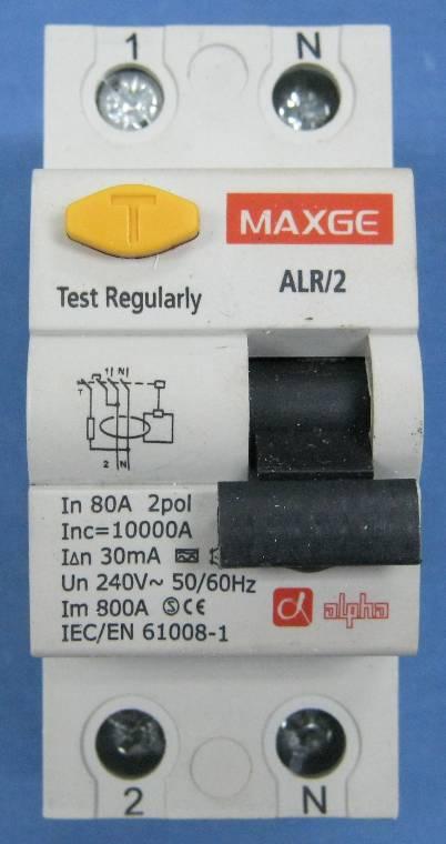
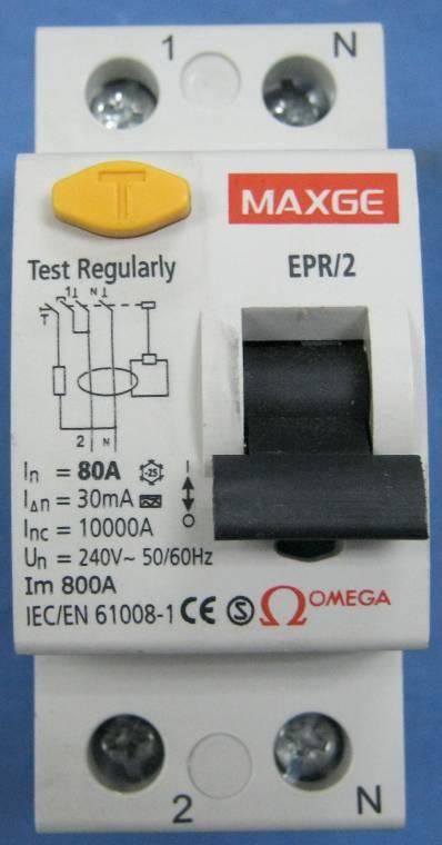
5 age 5 of 292 Report No SHA-001 Copy of marking plate:
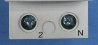
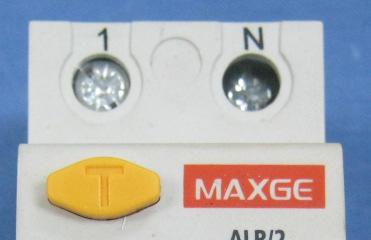
6 age 6 of 292 Report No SHA-001 Test item particulars... : Classification of RCCBs functionally dependent on the line voltage... : Opening automatically in case of failure of the line voltage... : - reclosing automatically when the line voltage is restored... : - not reclosing automatically when the line voltage is restored... : Not opening automatically in case of failure of the line voltage... : - able to trip in a hazardous situation arising on failure of line voltage... : - not able to trip in a hazardous situation arising on failure of line voltage... : Yes / No Yes / No Yes / No Yes / No Yes / No Yes / No Yes / No Type of RCCB... : - type AC... : Yes / No - type A... : Yes / No - independent of the line voltage... : Yes / No - dependent on the line voltage... : Yes / No - without time delay... : Yes / No - with time delay: type S... : Yes / No - enclosed... : Yes / No - unenclosed... : Yes / No - I number... : 20 ( for built in use) - for fixed installation... : Yes - for mobile installation... : No Number of poles... : 2(1+N) Ambient air temperature ( C)... : -25 ~ +40 Method of mounting... : Din rail mounting Method of connection... : Screw in Rated residual operating current (A)... : 0,01; 0,03; 0,1; 0,3 Rated current (A)... : 16, 20, 25, 32, 40, 50, 63, 80 Rated voltage (V)... : 240 Rated impulse withstand voltage (U imp ) 4kV Nature of supply... : ~ Rated frequency (Hz)... : 50/60
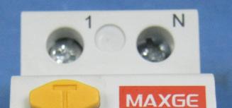
7 age 7 of 292 Report No SHA-001 Rated making and breaking capacity (A)... : 10In(63, 80A), 500A(16, 20, 25, 32, 40, 50A) Rated residual making and breaking capacity (A)... : Same as above Rated conditional short-circuit current (A)... : 6000, Rated conditional residual short-circuit current (A)... : Same as above Type of terminal... : Screw in ossible test case verdicts: - test case does not apply to the test object... : - test object does meet the requirement... : (ass) - test object does not meet the requirement... : F (Fail) Testing... : Date of receipt of test item... : Date (s) of performance of tests... : From to General remarks: The test results presented in this report relate only to the object tested. This report shall not be reproduced, except in full, without the written approval of the Issuing testing laboratory. "(see Enclosure #)" refers to additional information appended to the report. "(see appended table)" refers to a table appended to the report. Throughout this report a comma / point is used as the decimal separator. Manufacturer s Declaration per sub-clause of IECEE 02: The application for obtaining a CB Test Certificate includes more than one factory location and a declaration from the Manufacturer stating that the sample(s) submitted for evaluation is (are) representative of the products from each factory has been provided...: Yes Not applicable When differences exist; they shall be identified in the General product information section. Name and address of factory (ies)... : ZHEJIANG MAXGE ELECTRIC TECHNOLOGY CO., LTD. General product information: Un= 240V~(1+N), 415V~(3+N) In=16, 20, 25, 32, 40, 50, 63, 80A Type A and AC(30mA, 100mA, 300mA) for 16A to 80A; Type A and AC(10mA) for 16A to 25A I c = Inc =6000A&10000A No.299 East Changhong Road, Deqing Economic zone, Wukang, Deqing, ZHEJIANG, CHINA Note: 1: SGR, ER and ALR are the same internal instruction except for the enclosure shape. 2: The ratings of I c and Inc tested in the reports are 10000A.
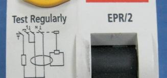
8 age 8 of 292 Report No.: SHA-001 TEST SEQUENCE A 1 (1 sample: In= 80A, I n= 0,03A, type A ) A Marking a) manufacturer's name or trademark...: b) type designation, catalogue number or serial number...: SGR c) rated voltage(s) (V)...: 240V~ d) rated frequency (Hz)...: 50/60Hz e) rated current (A)...: 80A f) rated residual operating current (A)...: 30mA h) rated making and breaking capacity (A)...: 800A j) degree of protection...: k) position of use...: l) rated residual making and breaking capacity (A)...: m) symbol S for type S S n) symbol of the method of operation...: o) operating means of test device...: T p) wiring diagram...: q) operating characteristic...: Marking on the RCCB itself or on nameplate or nameplates attached to the RCCB and located so that for small devices at least e), f), o) and q) (only for type A) are legible when the RCCB is installed : Joule integral withstand capacity (A²s)...: eak current withstand capacity (A)...: Time delay when opening in case of failure of the line voltage (s)...: Open position indicated by "0" and closed position O / I by "I"...: For push-buttons the OFF push-button shall either be red or marked with "0"...:
9 age 9 of 292 Report No.: SHA-001 If necessary to distinguish between supply and load terminals they shall be clearly marked...: Terminals for neutral conductor marked by "N" Terminals for protective conductor marked by [symbol IEC a] Marking indelible, easy legible and not on removable parts 9.3 Test: 15 s with water, 15 s with hexane For universal terminals (rigid-solid, rigid-stranded and flexible conductors: - no markings For non-universal terminals: - terminals for rigid-solid conductors only, marked by the letters s or sol - terminals for rigid (solid and stranded) conductors only, marked by the letter r marking on the RCCB or if the space available is not sufficient, on the smallest package unit or in technical information 8. Requirements for construction and operation General Residual current detection is located between the incoming and outgoing terminals Not possible to alter the operating characteristics by means of external interventions other than those specifically intended for changing the setting of the residual operating current Changing from one setting to another shall not be possible without a tool In case of an RCCB having multiple settings of residual operating current the rating refers to the highest setting Mechanism Moving contacts of all poles so mechanically coupled that all poles except the switched neutral, make and break substantially together
10 age 10 of 292 Report No.: SHA-001 Switched neutral opens after and closes before other poles Compliance is checked by inspection and by manual tests, using any appropriate means (e.g.: indicator lights, oscilloscope, etc.) Trip-free mechanism 9.15 Test: the RCCB is mounted and wired as in normal use - test circuit according to fig. 4a - a residual current equal to 1,5 I n is passed by closing S2, the RCCB having been closed and the operating means being held in the closed position. The RCCB shall trip - test repeated by moving the operating means slowly (1 s) to a position where the current starts to flow. Tripping shall occur without further movement 45mA ossible to switch on and off by hand No intermediate positions of the contacts In the open position isolation distance in accordance with the requirements necessary to satisfy the isolating function Indication of the open and closed position of the main contacts shall be provided by one or both of the following means: - the position of the actuator (this being preferred) - a separate mechanical indicator If a separate mechanical indicator is used, this shall show the colour red for the closed position and the colour green for the open position means of indication of the contact position shall be reliable -checked by inspection and by the tests of 9.15
11 age 11 of 292 Report No.: SHA-001 RCCBs shall be designed so that the actuator, front plate or cover can only be correctly fitted in a manner which ensures correct indication of the contact position -checked by inspection and by the tests of 9.11 When means are provided or specified by the manufacturer to lock the operating means in the open position: locking only possible when the main contacts are in the open position If the operating means is used for indication, it shall, when released, automatically take up the position to that of the moving contacts; the operating means shall have two distinct rest positions except that for automatic opening a third distinct position may be provided, when necessary to reset before reclosing For RCCBs functionally dependent on line voltage, reclosing automatically when the line voltage is restored after failure, the operating means shall remain in the ON position and the contacts shall reclose automatically unless the operating means has been placed in the OFF position When an indicator light is used this shall be lit when the RCCB is in the closed position The indicator light shall not be the only means to indicate the closed position The action of the mechanism shall not be influenced by the position of enclosures or covers and shall be independent of any removable part. If the cover is used as a guiding means for pushbuttons, it shall not be possible to remove the buttons from the outside Operating means securely fixed; not possible to remove them without a tool No such locking
12 age 12 of 292 Report No.: SHA-001 For "up-down" operating means the contacts shall be closed by the up movement Screws, current-carrying parts and connections Connections withstand mechanical stresses occurring in normal use Screws for mounting the RCCB are not of threadcutting type 9.4 Screws and nuts which are operated when mounting and connecting comply with the test of 9.4 Torque test: - torque (Nm); 5/10 times; diameter (mm)...: 2,5Nm; 5 times; 5,9mm Screws with a thread of insulating material operated when mounting the RCCB: correct introduction ensured Electrical connections: contact pressure not transmitted through insulating material unless there is sufficient resilience in the metallic parts Current-carrying parts including parts intended for protective conductors, if any, shall be made of a metal having, under the conditions occurring in the equipment, mechanical strength, electrical conductivity and resistance to corrosion adequate for their intended use. Examples below: - copper - an alloy 58% copper for parts worked cold - an alloy 50% copper for other parts - other metal In case of using ferrous alloys or suitably coated ferrous alloys, compliance to resistance to corrosion is checked by a test of resistance to rusting (see 9.25). The requirements of this subclause do not apply to: contacts, magnetic circuits, heater elements, bimetals, shunts, parts of electronic devices or to screws, nuts, washers, clamping plates, similar parts of terminals and parts of the test circuit Terminals for external conductors
13 age 13 of 292 Report No.: SHA-001 Compliance is checked by inspection and by the tests as relevant for the type of connection: 9.5 for screw-type terminals by specific tests for plug-in or bolt-on RCCBs included in the standard by the tests of Annexes J, K or L Terminals ensure the necessary contact pressure 9.5 Torque test: - torque (Nm); diameter (mm)...: 2,5Nm; 5,9mm - max. cross-sectional area (mm²)...: 25mm ull test: Terminal shall be suitable for all types of conductors: rigid (solid or stranded) and flexible, unless otherwise specified by the manufacturer. Min. cross-section solid / stranded / flexible (mm²)... 1,0mm² Max. cross-section solid / stranded / flexible (mm²)... 25mm² Torque 2 / 3 (Nm)... 1,67Nm ull for 1 min solid / stranded / flexible (N)... 50N for 1,0mm 2 During the test no noticeable move of conductor 100N for 25mm Torque test: - torque (2/3) (Nm)...: 1,67Nm - min. cross-sectional area (mm²)...: 1,0 mm² - max. cross-sectional area (mm²)...: 25 mm² The conductor shows no damage Terminals have not worked loose and no damage Terminals fitted with the largest cross-section area specified in Table 6, for stranded and/or flexible copper conductor. 1,0 to 25 mm² Max. cross-section stranded (mm²) mm² Max. cross-section flexible (mm²) mm² Torque 2 / 3 (Nm)... 1,67 Nm After the test no strand of conductor escaped outside RCCBs shall be provided with:
14 age 14 of 292 Report No.: SHA terminals which shall allow the connection of copper conductors having nominal crosssectional areas as shown in Table 6 Rated current (A) Range of nominal cross sections to be clamped* (mm²) Rigid (solid or stranded) conductors Flexible conductors 13 1 to 2,5 1 to 2,5 > to 4 1 to 4 > ,5 to 6 1,5 to 6 > ,5 to 10 2,5 to 6 > to 16 4 to 10 > to to 16 > to to 25 > to to 35 *It is required that, for current ratings up to and including 50 A, terminals be designed to clamp solid conductors as well as rigid stranded conductors. Nevertheless, it is permitted that terminals for conductors having cross-sections from 1 mm² up to 6 mm² be designed to clamp solid conductors only. - or terminals for external untreated aluminium conductors and with aluminium screw-type terminals for use with copper or with aluminium conductors according to Annex L Means for clamping the conductors in the terminals do not serve to fix any other component (see tests of 9.5) Terminals for In 32 A allow the connection of conductors without special preparation Terminals shall have adequate mechanical strength and metric ISO thread or equivalent (see tests of 9.4 and 9.5.1) Clamping of conductor without undue damage to conductor (see tests of 9.5.2) Clamping of conductor reliably and between metal surfaces (see tests of 9.4 and 9.5.1) Terminals so designed or positioned that no conductor can slip out while the clamping screws or nuts are tightened (see tests of ) Stranded 1,0mm² to 25mm² Flexible 1,0mm² to 16mm² The terminal is designed for solid conductors of 1-6 mm².
15 age 15 of 292 Report No.: SHA Terminals so fixed or located that they do not work loose when the clamping screws or nuts are tightened or loosened (see tests of 9.4) Clamping screws or nuts of terminals for the protective conductors adequately secured against accidental loosening and not possible to unclamp without a tool Screws and nuts of terminals for external conductors shall be in engagement with a metal thread and the screws shall not be of the tapping screw type 8.2 rotection against electric shock Live parts not accessible in normal use For RCCBs other than plug-in type, external parts, other than screws or other means for fixing covers, which are accessible in normal use shall be of insulating material or be lined throughout with insulating material Lining reliably fixed Lining has adequate thickness and mechanical strength Inlet openings for cables or conduits shall be of insulating material or be provided with bushings or similar devices of insulating material Such devices shall be reliably fixed Such devices shall have adequate mechanical strength For plug-in RCCBs, external parts, other than screws or other means for fixing covers, which are accessible, shall be of insulating material Metallic operating means insulated from live parts Metal parts of the mechanism not accessible, insulated from accessible metal parts, from metal frames (for flush-type), from screws or other means for fixing the base and from metal plates
16 age 16 of 292 Report No.: SHA-001 ossible to replace plug-in RCCBs easily without touching live parts Lacquer or enamel not considered to provide adequate insulation 9.6 Test: verify with test finger, 1 min with a force of 75 N Enclosures or covers not deformed to such an extent that live parts can be touched 8.9 Resistance to heat RCCB sufficiently resistant to heat Test: 1 h; test temperature ( C): (100 ± 2) C for not removable covers or (70 ± 2) C for removable covers...: No change impairing further use and no flow of sealing compound so that live parts are exposed No access to live parts even if the test finger is applied with a force not exceeding 5 N 100 C The RCCB shall trip with a test current of 1,25 I n (ms)...: Marking still legible after test Trip, 25ms Ball-pressure test for external parts of insulating material (parts retaining live parts in position); test temperature: 125 C ± 2 C for 1 h; diameter of impression (mm): 2 mm...: Ball-pressure test for external parts of insulating material (parts not retaining live parts in position); test temperature ( C): (70 ± 2) C or (40 ± 2) C + max. temperature rise of 9.8; diameter of impression (mm): 2 mm...: 1,5 mm(enclosure) 1,0 mm(handle) Clearances and creepage distances (internal and external parts) The minimum required clearances and creepage distances are based on the RCCB being designed for operating in an environment with pollution degree 2
17 age 17 of 292 Report No.: SHA-001 Compliance for item 1 in is checked by measurement and by the test of and The test is carried out with samples not submitted to the humidity treatment described in The clearances of items 2 and 4 may be reduced provided that the measured clearances are not shorter than the minimum allowed in IEC for homogenous field conditions. In this case, after the humidity treatment in 9.7.1, compliance for item 2 and 4 and arrangements of items b), c), d) and e) is checked: - Tests according to to as applicable - Test according to with test voltages acc. Table 16 with test arrangements of items b), c), d), e) If measurement does not show any reduced clearance, test is not applied Compliance for item 3, checked by measurement arts of CBs connected to the live parts protected against pollution by the use of a type 2 protection according to IEC are exempt from this verification The insulating materials are classified into Material Groups on the basis of their comparative tracking index (CTI) acc. to IEC and measured according to IEC Clearances [mm] U imp 4kV (see table 5) 2,5kV(see table 5) Minimum clearances (see table 5) minimum clearances [mm] 1. between live parts which are separated when the main contacts are in the open position 5,0mm 2. between live parts of different polarity >5,0mm 3. between circuits supplied from different sources, one of which being ELV or SELV 4. between live parts and: - accessible surfaces of operating means >5,0mm - screws or other means for fixing covers which have to be removed when mounting the RCCB - surface on which the RCCB is mounted - screws or other means for fixing the RCCB
18 age 18 of 292 Report No.: SHA metal covers or boxes - other accessible metal parts >10,0mm - metal frames supporting flush-type RCCBs >10,0mm Minimum creepage distances (see table 5) Material group 1. between live parts which are separated when the main contacts are in the open position IIIb IIIa II I minimum creepage distances [mm] 5,1mm 2. between live parts of different polarity >5,0mm 3. between circuits supplied from different sources, one of which being ELV or SELV 4. between live parts and: - accessible surfaces of operating means >5,0mm - screws or other means for fixing covers which have to be removed when mounting the RCCB - surface on which the RCCB is mounted - screws or other means for fixing the RCCB - metal covers or boxes - other accessible metal parts >10,0mm - metal frames supporting flush-type RCCBs >10,0mm 9.25 Test of resistance to rusting: - 10 min immersed in a cold chemical degreaser such as methyl-chloroform or refined petrol - 10 min immersed in a 10% solution of ammonium chloride in water at 20 C±5 C - 10 min in a box containing air saturated with moisture at 20 C±5 C - 10 min at 100 C No sign of rust TEST SEQUENCE A 2 A 2-1 A 2-2 A 2-3 (3 samples: In= 80A, I n = 0,03A, type A) 8.10 Resistance to abnormal heat and fire
19 age 19 of 292 Report No.: SHA-001 External parts of insulating material shall not be liable to ignite and to spread fire under fault or overload conditions 9.14 Glow wire test Test performed on a complete RCCB Glow-wire test: ( ) C for external parts of 960(Enclosure) insulating material retaining current-carrying parts or parts of the protective circuit in position Glow-wire test: ( ) C for all other external 650(Handle) parts insulating material No visible flames, no sustained glowing, or No flames(handle) flames and glowing extinguish within 30 s after 2,9s(Enclosure) removal... : No ignition of tissue paper or scorching of the pinewood board TEST SEQUENCE A 1 (1 sample: In= 25A, I n= 0,01A, type A ) A Marking a) manufacturer's name or trademark...: b) type designation, catalogue number or serial number...: SGR c) rated voltage(s) (V)...: 240V~ d) rated frequency (Hz)...: 50/60Hz e) rated current (A)...: 25A f) rated residual operating current (A)...: 10mA h) rated making and breaking capacity (A)...: 500A j) degree of protection...: k) position of use...: l) rated residual making and breaking capacity (A)...: m) symbol S for type S S n) symbol of the method of operation...: o) operating means of test device...: T
20 age 20 of 292 Report No.: SHA-001 p) wiring diagram...: q) operating characteristic...: Marking on the RCCB itself or on nameplate or nameplates attached to the RCCB and located so that for small devices at least e), f), o) and q) (only for type A) are legible when the RCCB is installed : Joule integral withstand capacity (A²s)...: eak current withstand capacity (A)...: Time delay when opening in case of failure of the line voltage (s)...: Open position indicated by "0" and closed position by "I"...: For push-buttons the OFF push-button shall either be red or marked with "0"...: If necessary to distinguish between supply and load terminals they shall be clearly marked...: Terminals for neutral conductor marked by "N" Terminals for protective conductor marked by [symbol IEC a] Marking indelible, easy legible and not on removable parts O / I 9.3 Test: 15 s with water, 15 s with hexane For universal terminals (rigid-solid, rigid-stranded and flexible conductors: - no markings For non-universal terminals: - terminals for rigid-solid conductors only, marked by the letters s or sol - terminals for rigid (solid and stranded) conductors only, marked by the letter r marking on the RCCB or if the space available is not sufficient, on the smallest package unit or in technical information 8. Requirements for construction and operation General
21 age 21 of 292 Report No.: SHA-001 Residual current detection is located between the incoming and outgoing terminals Not possible to alter the operating characteristics by means of external interventions other than those specifically intended for changing the setting of the residual operating current Changing from one setting to another shall not be possible without a tool In case of an RCCB having multiple settings of residual operating current the rating refers to the highest setting Mechanism Moving contacts of all poles so mechanically coupled that all poles except the switched neutral, make and break substantially together Switched neutral opens after and closes before other poles Compliance is checked by inspection and by manual tests, using any appropriate means (e.g.: indicator lights, oscilloscope, etc.) Trip-free mechanism 9.15 Test: the RCCB is mounted and wired as in normal use - test circuit according to fig. 4a - a residual current equal to 1,5 I n is passed by 15mA closing S2, the RCCB having been closed and the operating means being held in the closed position. The RCCB shall trip - test repeated by moving the operating means slowly (1 s) to a position where the current starts to flow. Tripping shall occur without further movement ossible to switch on and off by hand No intermediate positions of the contacts
22 age 22 of 292 Report No.: SHA-001 In the open position isolation distance in accordance with the requirements necessary to satisfy the isolating function Indication of the open and closed position of the main contacts shall be provided by one or both of the following means: - the position of the actuator (this being preferred) - a separate mechanical indicator If a separate mechanical indicator is used, this shall show the colour red for the closed position and the colour green for the open position means of indication of the contact position shall be reliable -checked by inspection and by the tests of 9.15 RCCBs shall be designed so that the actuator, front plate or cover can only be correctly fitted in a manner which ensures correct indication of the contact position -checked by inspection and by the tests of 9.11 When means are provided or specified by the manufacturer to lock the operating means in the open position: locking only possible when the main contacts are in the open position If the operating means is used for indication, it shall, when released, automatically take up the position to that of the moving contacts; the operating means shall have two distinct rest positions except that for automatic opening a third distinct position may be provided, when necessary to reset before reclosing No such locking
23 age 23 of 292 Report No.: SHA-001 For RCCBs functionally dependent on line voltage, reclosing automatically when the line voltage is restored after failure, the operating means shall remain in the ON position and the contacts shall reclose automatically unless the operating means has been placed in the OFF position When an indicator light is used this shall be lit when the RCCB is in the closed position The indicator light shall not be the only means to indicate the closed position The action of the mechanism shall not be influenced by the position of enclosures or covers and shall be independent of any removable part. If the cover is used as a guiding means for pushbuttons, it shall not be possible to remove the buttons from the outside Operating means securely fixed; not possible to remove them without a tool For "up-down" operating means the contacts shall be closed by the up movement Screws, current-carrying parts and connections Connections withstand mechanical stresses occurring in normal use Screws for mounting the RCCB are not of threadcutting type 9.4 Screws and nuts which are operated when mounting and connecting comply with the test of 9.4 Torque test: - torque (Nm); 5/10 times; diameter (mm)...: 2,5Nm; 5 times; 5,9mm Screws with a thread of insulating material operated when mounting the RCCB: correct introduction ensured
24 age 24 of 292 Report No.: SHA Electrical connections: contact pressure not transmitted through insulating material unless there is sufficient resilience in the metallic parts Current-carrying parts including parts intended for protective conductors, if any, shall be made of a metal having, under the conditions occurring in the equipment, mechanical strength, electrical conductivity and resistance to corrosion adequate for their intended use. Examples below: - copper - an alloy 58% copper for parts worked cold - an alloy 50% copper for other parts - other metal In case of using ferrous alloys or suitably coated ferrous alloys, compliance to resistance to corrosion is checked by a test of resistance to rusting (see 9.25). The requirements of this subclause do not apply to: contacts, magnetic circuits, heater elements, bimetals, shunts, parts of electronic devices or to screws, nuts, washers, clamping plates, similar parts of terminals and parts of the test circuit Terminals for external conductors Compliance is checked by inspection and by the tests as relevant for the type of connection: 9.5 for screw-type terminals by specific tests for plug-in or bolt-on RCCBs included in the standard by the tests of Annexes J, K or L Terminals ensure the necessary contact pressure 9.5 Torque test: - torque (Nm); diameter (mm)...: 2,5Nm; 5,9mm - max. cross-sectional area (mm²)...: 6mm ull test: Terminal shall be suitable for all types of conductors: rigid (solid or stranded) and flexible, unless otherwise specified by the manufacturer. Min. cross-section solid / stranded / flexible (mm²)... 1,0mm² Max. cross-section solid / stranded / flexible (mm²)... 6mm²
25 age 25 of 292 Report No.: SHA-001 Torque 2 / 3 (Nm)... 1,67Nm ull for 1 min solid / stranded / flexible (N)... 50N for 1,0mm 2 During the test no noticeable move of conductor 60N for 6mm Torque test: - torque (2/3) (Nm)...: 1,67Nm - min. cross-sectional area (mm²)...: 1,0 mm² - max. cross-sectional area (mm²)...: 6 mm² The conductor shows no damage Terminals have not worked loose and no damage Terminals fitted with the largest cross-section area specified in Table 6, for stranded and/or flexible copper conductor. Max. cross-section stranded (mm²)... 6 mm² Max. cross-section flexible (mm²)... 6 mm² Torque 2 / 3 (Nm)... 1,67 Nm After the test no strand of conductor escaped outside RCCBs shall be provided with: - terminals which shall allow the connection of copper conductors having nominal crosssectional areas as shown in Table 6 Rated current (A) Range of nominal cross sections to be clamped* (mm²) Rigid (solid or stranded) conductors Flexible conductors 13 1 to 2,5 1 to 2,5 > to 4 1 to 4 > ,5 to 6 1,5 to 6 > ,5 to 10 2,5 to 6 > to 16 4 to 10 > to to 16 > to to 25 > to to 35 *It is required that, for current ratings up to and including 50 A, terminals be designed to clamp solid conductors as well as rigid stranded conductors. Nevertheless, it is permitted that terminals for conductors having cross-sections from 1 mm² up to 6 mm² be designed to clamp solid conductors only. Stranded 1,0mm² to 6mm² Flexible 1,0mm² to 6mm² The terminal is designed for solid conductors of 1-6 mm².
26 age 26 of 292 Report No.: SHA or terminals for external untreated aluminium conductors and with aluminium screw-type terminals for use with copper or with aluminium conductors according to Annex L Means for clamping the conductors in the terminals do not serve to fix any other component (see tests of 9.5) Terminals for In 32 A allow the connection of conductors without special preparation Terminals shall have adequate mechanical strength and metric ISO thread or equivalent (see tests of 9.4 and 9.5.1) Clamping of conductor without undue damage to conductor (see tests of 9.5.2) Clamping of conductor reliably and between metal surfaces (see tests of 9.4 and 9.5.1) Terminals so designed or positioned that no conductor can slip out while the clamping screws or nuts are tightened (see tests of ) Terminals so fixed or located that they do not work loose when the clamping screws or nuts are tightened or loosened (see tests of 9.4) Clamping screws or nuts of terminals for the protective conductors adequately secured against accidental loosening and not possible to unclamp without a tool Screws and nuts of terminals for external conductors shall be in engagement with a metal thread and the screws shall not be of the tapping screw type 8.2 rotection against electric shock Live parts not accessible in normal use
27 age 27 of 292 Report No.: SHA-001 For RCCBs other than plug-in type, external parts, other than screws or other means for fixing covers, which are accessible in normal use shall be of insulating material or be lined throughout with insulating material Lining reliably fixed Lining has adequate thickness and mechanical strength Inlet openings for cables or conduits shall be of insulating material or be provided with bushings or similar devices of insulating material Such devices shall be reliably fixed Such devices shall have adequate mechanical strength For plug-in RCCBs, external parts, other than screws or other means for fixing covers, which are accessible, shall be of insulating material Metallic operating means insulated from live parts Metal parts of the mechanism not accessible, insulated from accessible metal parts, from metal frames (for flush-type), from screws or other means for fixing the base and from metal plates ossible to replace plug-in RCCBs easily without touching live parts Lacquer or enamel not considered to provide adequate insulation 9.6 Test: verify with test finger, 1 min with a force of 75 N Enclosures or covers not deformed to such an extent that live parts can be touched 8.9 Resistance to heat RCCB sufficiently resistant to heat Test: 1 h; test temperature ( C): (100 ± 2) C for not removable covers or (70 ± 2) C for removable covers...: 100 C
28 age 28 of 292 Report No.: SHA-001 No change impairing further use and no flow of sealing compound so that live parts are exposed No access to live parts even if the test finger is applied with a force not exceeding 5 N The RCCB shall trip with a test current of 1,25 I n (ms)...: Marking still legible after test Trip, 17ms Ball-pressure test for external parts of insulating material (parts retaining live parts in position); test temperature: 125 C ± 2 C for 1 h; diameter of impression (mm): 2 mm...: Ball-pressure test for external parts of insulating material (parts not retaining live parts in position); test temperature ( C): (70 ± 2) C or (40 ± 2) C + max. temperature rise of 9.8; diameter of impression (mm): 2 mm...: 1,5 mm(enclosure) 1,0 mm(handle) Clearances and creepage distances (internal and external parts) The minimum required clearances and creepage distances are based on the RCCB being designed for operating in an environment with pollution degree 2 Compliance for item 1 in is checked by measurement and by the test of and The test is carried out with samples not submitted to the humidity treatment described in The clearances of items 2 and 4 may be reduced provided that the measured clearances are not shorter than the minimum allowed in IEC for homogenous field conditions. In this case, after the humidity treatment in 9.7.1, compliance for item 2 and 4 and arrangements of items b), c), d) and e) is checked: - Tests according to to as applicable - Test according to with test voltages acc. Table 16 with test arrangements of items b), c), d), e) If measurement does not show any reduced clearance, test is not applied Compliance for item 3, checked by measurement
29 age 29 of 292 Report No.: SHA-001 arts of CBs connected to the live parts protected against pollution by the use of a type 2 protection according to IEC are exempt from this verification The insulating materials are classified into Material Groups on the basis of their comparative tracking index (CTI) acc. to IEC and measured according to IEC Clearances [mm] U imp 4kV (see table 5) 2,5kV(see table 5) Minimum clearances (see table 5) minimum clearances [mm] 1. between live parts which are separated when the main contacts are in the open position 5,0mm 2. between live parts of different polarity 3,8mm 3. between circuits supplied from different sources, one of which being ELV or SELV 4. between live parts and: - accessible surfaces of operating means 4,3mm - screws or other means for fixing covers which have to be removed when mounting the RCCB - surface on which the RCCB is mounted - screws or other means for fixing the RCCB - metal covers or boxes - other accessible metal parts >10,0mm - metal frames supporting flush-type RCCBs >10,0mm Minimum creepage distances (see table 5) Material group 1. between live parts which are separated when the main contacts are in the open position IIIb IIIa II I minimum creepage distances [mm] 5,1mm 2. between live parts of different polarity 4,7mm 3. between circuits supplied from different sources, one of which being ELV or SELV 4. between live parts and: - accessible surfaces of operating means 4,5mm
30 age 30 of 292 Report No.: SHA screws or other means for fixing covers which have to be removed when mounting the RCCB - surface on which the RCCB is mounted - screws or other means for fixing the RCCB - metal covers or boxes - other accessible metal parts >10,0mm - metal frames supporting flush-type RCCBs >10,0mm 9.25 Test of resistance to rusting: - 10 min immersed in a cold chemical degreaser such as methyl-chloroform or refined petrol - 10 min immersed in a 10% solution of ammonium chloride in water at 20 C±5 C - 10 min in a box containing air saturated with moisture at 20 C±5 C - 10 min at 100 C No sign of rust TEST SEQUENCE A 2 A 2-4 A 2-5 A 2-6 (3 samples: In= 25A, I n = 0,01A, type A) 8.10 Resistance to abnormal heat and fire External parts of insulating material shall not be liable to ignite and to spread fire under fault or overload conditions 9.14 Glow wire test Test performed on a complete RCCB Glow-wire test: ( ) C for external parts of insulating material retaining current-carrying parts or parts of the protective circuit in position Glow-wire test: ( ) C for all other external parts insulating material 960(Enclosure) 650(Handle) No visible flames, no sustained glowing, or No flames(handle) flames and glowing extinguish within 30 s after removal... : No ignition of tissue paper or scorching of the pinewood board 2,9s(Enclosure)
31 age 31 of 292 Report No.: SHA-001 TEST SEQUENCE B (3 samples: In= 80A, I n= 0,03A, type A) B1 B2 B3 8 REQUIREMENTS FOR CONSTRUCTION AND OERATION 8.3 DIELECTRIC ROERTIES AND ISOLATING CAABILITY RCCBs have adequate dielectric properties 9.7 TEST OF DIELECTRIC ROERTIES AND ISOLATING CAABILITY VERIFICATION OF RESISTANCE OF THE INSULATION OF OEN CONTACT AND BASIC INSULATION AGAINST AN IMULSE VOLTAGE IN NORMAL CONDITIONS These tests are not preceded by the humidity treatment described in The test is carried out on an RCCB fixed on a metal support The impulses are given by a generator producing positive and negative impulses having a front time of 1,2µs, and a time to half-value of 50µs The shape of the impulses is adjusted with the RCCB under test connected to the impulse generator. For RCCBs with incorporated surge arresters that cannot be disconnected, the shape of the impulses is adjusted without connection of the RCCB to the impulse generator. 1,2/50µs rated impulse withstand voltage [kv]: 4 kv see level of test laboratory [m] 5m test voltage (acc. Table 22) [kv]: 6,2kV RCCB in open position (contacts in open position) The impulses are applied between: the line terminals connected together and the load terminals connected together RCCB in closed position All components bridging the basic insulation disconnected A first series of tests is made applying the impulse voltage between the phase pole(s) and the neutral pole (or path) connected together and the metal support connected to the terminal(s) intended for the protective conductor(s), if any A second series of tests is made applying the impulse voltage between the phase pole(s), connected together, and the neutral pole (or path) of the RCCB
32 age 32 of 292 Report No.: SHA-001 Five positive impulses and five negative impulses are applied, the interval between consecutive impulses being at least 1 s for impulses of the same polarity and being at least 10 s for impulses of the opposite polarity. no disruptive discharges during the test VERIFICATION OF THE BEHAVIOUR OF COMONENTS BRIDGING THE BASIC INSULATION A new RCCB sample is tested Test only performed on RCCBs, where components bridging the basic insulation have been disconnected during the impulse voltage test of test voltage 1200V+U 0 The voltage is applied during 5s between the phase pole(s) and the neutral pole (or path) connected together and the metal support connected to the terminal(s) intended for the prospective conductor(s), if any after test, no component bridging the basic insulation should show a visible alteration. Then, the equipment is connected to the mains acc. manufacturer s instruction The RCCB shall trip with a test current of 1,25 I N Test switch S 2 and RCCB in the closed position, test voltage established by closing the test switch S RESISTANCE TO HUMIDITY arts which can be removed without a tool are removed, spring lids kept open, inlet openings are left open and if knock-outs one is opened Test conditions: 48 h in humidity cabinet RH = 91% to 95% T = 20 to 30 C ± 1 C RH = 93% T = 25 C The samples show no damage Insulation resistance of the main circuit measured between 30 and 60 min after this treatment with 500 V DC after 5 s: B1 [MΩ] [ms] B2 [MΩ] B3 [MΩ] a) between the terminals which are electrically > 2000 > 2000 > 2000 connected together when the RCCB is in the closed position... 2 MΩ b) between each pole and the others connected > 2000 > 2000 > 2000 together (electronic components, connected between current path being disconnected)... 2 MΩ
33 age 33 of 292 Report No.: SHA-001 c) between all poles connected together and the > 2000 > 2000 > 2000 frame... 5 MΩ d) between metal parts of the mechanism and the frame... 5 MΩ e) between the frame and a metal foil in contact with the inner surface of the lining of insulating material... 5 MΩ Dielectric strength of the main circuit measured with an AC voltage (45-65Hz) for 1 min: a) electronic components disconnected V b) electronic components disconnected V c) electronic components disconnected V d) electronic components disconnected V e) electronic components disconnected V No flashover or breakdown Insulation resistance of auxiliary circuits measured with 500 V DC after 1 min: 1) between all auxiliary circuits and the frame... 2 MΩ 2) between each part of the auxiliary circuits which might be isolated from the other parts and the whole of the other parts connected together... 2 MΩ Dielectric strength of auxiliary circuits measured with an AC voltage at rated frequency for 1 min: Rated voltage of auxiliary circuits (a.c. or d.c.) Test voltage (V) > > > > V B1 [MΩ] B2 [MΩ] B3 [MΩ] 1) between all auxiliary circuits and the frame 2) between each part of the auxiliary circuits which might be isolated from the other parts and the whole of the other parts connected together No flashover or perforation Verification of clearances with the impulse withstand voltage If the measurement of clearances of items 2 and 4 in Table 5 shows a reduction of the required length, this test applies.
34 age 34 of 292 Report No.: SHA-001 The test is carried out on an RCCB fixed on a metal support and being in the closed position The impulses are given by a generator producing positive and negative impulses having a front time of 1,2µs, and a time to half-value of 50µs The shape of the impulses is adjusted with the RCCB under test connected to the impulse generator. For RCCBs with incorporated surge arresters that cannot be disconnected, the shape of the impulses is adjusted without connection of the RCCB to the impulse generator. 1,2/50µs test performed with: - surge impedance of the test apparatus 500Ω and surge protective devices disconnected before testing or - hybrid generator with an surge impedance of 2 Ω and surge protective devices not diconnected before testing rated impulse withstand voltage [kv]: 4kV see level of test laboratory [m] 5m test voltage (acc. Table 16) [kv]: 4,9kV A first series of tests is made applying the impulse voltage between the phase pole(s) and the neutral pole (or path) connected together and the metal support connected to the terminal(s) intended for the protective conductor(s), if any A second series of tests is made applying the impulse voltage between the phase pole(s), connected together, and the neutral pole (or path) of the RCCB A third series of tests is made applying the impulse voltage between (and not tested during the two first sequences described here above): b) between each pole and the others connected together (electronic components, connected between current path being disconnected) c) between all poles connected together and the frame d) between metal parts of the mechanism and the frame e) between the frame and a metal foil in contact with the inner surface of the lining of insulating material
35 age 35 of 292 Report No.: SHA-001 Five positive impulses and five negative impulses are applied, the interval between consecutive impulses being at least 1 s for impulses of the same polarity and being at least 10 s for impulses of the opposite polarity. no disruptive discharges during the test Secondary circuit of detection transformers No insulation test, provided that no connection with accessible metal parts or with protective conductor or live parts exists Capability of control circuits connected to the main circuit of withstanding high DC voltages due to insulation measurements RCCB fixed on metal support in closed position with all control circuits connected as in service. Open test voltage 600 V +25 / -0 V Maximum ripple 5% Short-circuit current 12 ma +2 / -0 ma Applied for 1 min between each pole and the other poles connected together to the frame. 600V 12,8mA 1min 600V 12,8mA 1min Type I N A I N A Standard values of break time and non-actuating time at a residual current equal to I N 2 I N 5 I N 5 I N or 0,25A a) 5A-200A, b) 600V 12,8mA 1min 500A General Any value <0,03 0,3 0,15 0,04 0,04 0,04 0,03 0,3 0,15 0,04 0,04 0,04 Max. break times >0,03 0,3 0,15 0,04 0,04 0,04 S 25 >0,03 0,5 0,2 0,15 0,15 0,15 Max. break times a) value to be decided by the manufacturer for this test b) The test are only made during verification of the correct operation as mentioned in Verification of the correct operation in case of sudden appearance of residual current by closing S 1, (S 2 and RCCB in closed position): 0,13 0,06 0,05 0,04 0,04 Min. nonactuating times Maximum break times at: [ms] [ms] [ms] - I N I N I N or ,25 A
36 age 36 of 292 Report No.: SHA I t A No value exceeds the relevant specified limiting value Additional test for type S: Minimum non-actuating time at: [ms] [ms] [ms] - I N... 0,13 s - 2 I N... 0,06 s - 5 I N... 0,05 s - I t... 0,04 s The test switch S 1 and the RCCB being in the closed position, the test voltage is suddenly established by closing the test switch S 2 for min. non-operating times acc. table 2 No tripping during tests 8.4 Temperature rise Temperature rises do not exceed the limiting values stated in table 7. Cross-section (mm²) 25mm² Ambient air temperature ( C) 24 C Test current I N (A) until steady state values are reached. Four pole RCCBs: Current passing through 80A - 3 phase poles (1) - neutral and adjacent pole (2) arts... Temperature rise K [K] [K] [K] Terminals for external connections External parts liable to be touched during manual operation of the RCCB, including operating means of insulating material and metallic means for coupling insulated operating means of several poles External metallic parts of operating means Other external parts, including that face of the RCCB in direct contact with the mounting surface Reliability RCCBs operate reliably even after long service Test with 28 cycles at 40 ± 2 C Cross-section (mm²)... 25mm² Torque 2 / 3 (Nm)... 1,67Nm
37 age 37 of 292 Report No.: SHA-001 Test current I N (A)... 80A - with current passing h - without current... 3 h For 4 pole RCCBs with 3 overcurrent protected poles only 3 poles loaded At the end of the last period of 21 h with current passing the temperature rise of the terminals shall not exceed 65K [K] [K] [K] After cool down the RCCB shall trip with a test current of 1,25 I N - break time not exceeding the value for I N in table 2 [ms] [ms] [ms] Test switch S 2 and RCCB in the closed position, test voltage established by closing the test switch S Verification of ageing of electronic components 168 h at 40 ± 2 C C Test current I N (A)... 80A Cross-section (mm²)... 25mm² Electronic parts at 1,1 U N V After cool down: - electronic parts show no damage The RCCB shall trip with a test current of 1,25 I N - break time not exceeding the value for I N in table 2 Test switch S 2 and RCCB in the closed position, test voltage established by closing the test switch S 1 [ms] [ms] [ms] TEST SEQUENCE B (3 samples: In= 25A, I n= 0,01A, type A) B4 B5 B6 8 REQUIREMENTS FOR CONSTRUCTION AND OERATION 8.3 DIELECTRIC ROERTIES AND ISOLATING CAABILITY RCCBs have adequate dielectric properties 9.7 TEST OF DIELECTRIC ROERTIES AND ISOLATING CAABILITY VERIFICATION OF RESISTANCE OF THE INSULATION OF OEN CONTACT AND BASIC INSULATION AGAINST AN IMULSE VOLTAGE IN NORMAL CONDITIONS These tests are not preceded by the humidity treatment described in
38 age 38 of 292 Report No.: SHA-001 The test is carried out on an RCCB fixed on a metal support The impulses are given by a generator producing positive and negative impulses having a front time of 1,2µs, and a time to half-value of 50µs The shape of the impulses is adjusted with the RCCB under test connected to the impulse generator. For RCCBs with incorporated surge arresters that cannot be disconnected, the shape of the impulses is adjusted without connection of the RCCB to the impulse generator. 1,2/50µs rated impulse withstand voltage [kv]: 4 kv see level of test laboratory [m] 5m test voltage (acc. Table 22) [kv]: 6,2kV RCCB in open position (contacts in open position) The impulses are applied between: the line terminals connected together and the load terminals connected together RCCB in closed position All components bridging the basic insulation disconnected A first series of tests is made applying the impulse voltage between the phase pole(s) and the neutral pole (or path) connected together and the metal support connected to the terminal(s) intended for the protective conductor(s), if any A second series of tests is made applying the impulse voltage between the phase pole(s), connected together, and the neutral pole (or path) of the RCCB Five positive impulses and five negative impulses are applied, the interval between consecutive impulses being at least 1 s for impulses of the same polarity and being at least 10 s for impulses of the opposite polarity. no disruptive discharges during the test VERIFICATION OF THE BEHAVIOUR OF COMONENTS BRIDGING THE BASIC INSULATION A new RCCB sample is tested Test only performed on RCCBs, where components bridging the basic insulation have been disconnected during the impulse voltage test of
39 age 39 of 292 Report No.: SHA-001 test voltage 1200V+U 0 The voltage is applied during 5s between the phase pole(s) and the neutral pole (or path) connected together and the metal support connected to the terminal(s) intended for the prospective conductor(s), if any after test, no component bridging the basic insulation should show a visible alteration. Then, the equipment is connected to the mains acc. manufacturer s instruction The RCCB shall trip with a test current of 1,25 I N Test switch S 2 and RCCB in the closed position, test voltage established by closing the test switch S RESISTANCE TO HUMIDITY arts which can be removed without a tool are removed, spring lids kept open, inlet openings are left open and if knock-outs one is opened Test conditions: 48 h in humidity cabinet RH = 91% to 95% T = 20 to 30 C ± 1 C RH = 93% T = 25 C The samples show no damage Insulation resistance of the main circuit measured between 30 and 60 min after this treatment with 500 V DC after 5 s: B4 [MΩ] [ms] B5 [MΩ] B6 [MΩ] a) between the terminals which are electrically > 2000 > 2000 > 2000 connected together when the RCCB is in the closed position... 2 MΩ b) between each pole and the others connected > 2000 > 2000 > 2000 together (electronic components, connected between current path being disconnected)... 2 MΩ c) between all poles connected together and the > 2000 > 2000 > 2000 frame... 5 MΩ d) between metal parts of the mechanism and the frame... 5 MΩ e) between the frame and a metal foil in contact with the inner surface of the lining of insulating material... 5 MΩ Dielectric strength of the main circuit measured with an AC voltage (45-65Hz) for 1 min: a) electronic components disconnected V b) electronic components disconnected V c) electronic components disconnected V
40 age 40 of 292 Report No.: SHA-001 d) electronic components disconnected V e) electronic components disconnected V No flashover or breakdown Insulation resistance of auxiliary circuits measured with 500 V DC after 1 min: 1) between all auxiliary circuits and the frame... 2 MΩ 2) between each part of the auxiliary circuits which might be isolated from the other parts and the whole of the other parts connected together... 2 MΩ Dielectric strength of auxiliary circuits measured with an AC voltage at rated frequency for 1 min: Rated voltage of auxiliary circuits (a.c. or d.c.) Test voltage (V) > > > > V B4 [MΩ] B5 [MΩ] B6 [MΩ] 1) between all auxiliary circuits and the frame 2) between each part of the auxiliary circuits which might be isolated from the other parts and the whole of the other parts connected together No flashover or perforation Verification of clearances with the impulse withstand voltage If the measurement of clearances of items 2 and 4 in Table 5 shows a reduction of the required length, this test applies. The test is carried out on an RCCB fixed on a metal support and being in the closed position The impulses are given by a generator producing positive and negative impulses having a front time of 1,2µs, and a time to half-value of 50µs The shape of the impulses is adjusted with the RCCB under test connected to the impulse generator. For RCCBs with incorporated surge arresters that cannot be disconnected, the shape of the impulses is adjusted without connection of the RCCB to the impulse generator. 1,2/50µs test performed with:
41 age 41 of 292 Report No.: SHA surge impedance of the test apparatus 500Ω and surge protective devices disconnected before testing or - hybrid generator with an surge impedance of 2 Ω and surge protective devices not diconnected before testing rated impulse withstand voltage [kv]: 4kV see level of test laboratory [m] 5m test voltage (acc. Table 16) [kv]: 4,9kV A first series of tests is made applying the impulse voltage between the phase pole(s) and the neutral pole (or path) connected together and the metal support connected to the terminal(s) intended for the protective conductor(s), if any A second series of tests is made applying the impulse voltage between the phase pole(s), connected together, and the neutral pole (or path) of the RCCB A third series of tests is made applying the impulse voltage between (and not tested during the two first sequences described here above): b) between each pole and the others connected together (electronic components, connected between current path being disconnected) c) between all poles connected together and the frame d) between metal parts of the mechanism and the frame e) between the frame and a metal foil in contact with the inner surface of the lining of insulating material Five positive impulses and five negative impulses are applied, the interval between consecutive impulses being at least 1 s for impulses of the same polarity and being at least 10 s for impulses of the opposite polarity. no disruptive discharges during the test Secondary circuit of detection transformers No insulation test, provided that no connection with accessible metal parts or with protective conductor or live parts exists.
42 age 42 of 292 Report No.: SHA Capability of control circuits connected to the main circuit of withstanding high DC voltages due to insulation measurements RCCB fixed on metal support in closed position with all control circuits connected as in service. Open test voltage 600 V +25 / -0 V Maximum ripple 5% Short-circuit current 12 ma +2 / -0 ma Applied for 1 min between each pole and the other poles connected together to the frame. 600V 12,8mA 1min 600V 12,8mA 1min Type I N A I N A Standard values of break time and non-actuating time at a residual current equal to I N 2 I N 5 I N 5 I N or 0,25A a) 5A-200A, b) 600V 12,8mA 1min 500A General Any value <0,03 0,3 0,15 0,04 0,04 0,04 Max. break times 0,03 0,3 0,15 0,04 0,04 0,04 >0,03 0,3 0,15 0,04 0,04 0,04 S 25 >0,03 0,5 0,2 0,15 0,15 0,15 Max. break times a) value to be decided by the manufacturer for this test b) The test are only made during verification of the correct operation as mentioned in Verification of the correct operation in case of sudden appearance of residual current by closing S 1, (S 2 and RCCB in closed position): 0,13 0,06 0,05 0,04 0,04 Min. nonactuating times Maximum break times at: [ms] [ms] [ms] - I N I N I N or ,25 A I t A No value exceeds the relevant specified limiting value Additional test for type S: Minimum non-actuating time at: [ms] [ms] [ms] - I N... 0,13 s - 2 I N... 0,06 s - 5 I N... 0,05 s
43 age 43 of 292 Report No.: SHA I t... 0,04 s The test switch S 1 and the RCCB being in the closed position, the test voltage is suddenly established by closing the test switch S 2 for min. non-operating times acc. table 2 No tripping during tests 8.4 Temperature rise Temperature rises do not exceed the limiting values stated in table 7. Cross-section (mm²) 4mm² Ambient air temperature ( C) 22 C Test current I N (A) until steady state values are reached. Four pole RCCBs: Current passing through 25A - 3 phase poles (1) - neutral and adjacent pole (2) arts... Temperature rise K [K] [K] [K] Terminals for external connections External parts liable to be touched during manual operation of the RCCB, including operating means of insulating material and metallic means for coupling insulated operating means of several poles External metallic parts of operating means Other external parts, including that face of the RCCB in direct contact with the mounting surface Reliability RCCBs operate reliably even after long service Test with 28 cycles at 40 ± 2 C Cross-section (mm²)... 4mm² Torque 2 / 3 (Nm)... 1,67Nm Test current I N (A)... 25A - with current passing h - without current... 3 h For 4 pole RCCBs with 3 overcurrent protected poles only 3 poles loaded At the end of the last period of 21 h with current passing the temperature rise of the terminals shall not exceed 65K [K] [K] [K]
44 age 44 of 292 Report No.: SHA-001 After cool down the RCCB shall trip with a test current of 1,25 I N - break time not exceeding the value for I N in table 2 [ms] [ms] [ms] Test switch S 2 and RCCB in the closed position, test voltage established by closing the test switch S Verification of ageing of electronic components 168 h at 40 ± 2 C C Test current I N (A)... 25A Cross-section (mm²)... 4mm² Electronic parts at 1,1 U N V After cool down: - electronic parts show no damage The RCCB shall trip with a test current of 1,25 I N - break time not exceeding the value for I N in table 2 Test switch S 2 and RCCB in the closed position, test voltage established by closing the test switch S 1 [ms] [ms] [ms]
45 age 45 of 292 Report No.: SHA-001 TEST SEQUENCE C (3 samples: In= 80A, I n= 0,03A, type A) C1 C2 C3 8.6 Mechanical and electrical endurance RCCBs shall be capable of performing an adequate number of mechanical and electrical operations 9.10 Test is made: - In 25 A; 2 s on; 13 s off... : - In > 25 A; 2 s on; 28 s off... : 80A Number of operating cycles: Test voltage Un (V); test current In (A); cos phi 0,85-0,9... : 240V, 80,4A, 0,86 Cross-sectional area (mm²)... : 25mm² RCCBs having I n > 0,010 A tested at: cycles for manual operation... : C1 - OK C2 - OK C3 - OK cycles by using the test device... : C1 - OK C2 - OK C3 - OK cycles at a current of I n... : C1 - OK C2 - OK C3 - OK RCCBs having I n 0,010 A tested at: cycles for manual operation... : C1 - C2 - C cycles by using the test device... : C1 - C2 - C cycles at a current of I n... : C1 - C2 - C3 - Test is made without load using manual operation:
46 age 46 of 292 Report No.: SHA In 25 A; 2000 cycles... : C1 - C2 - C3 - - In > 25 A; 1000 cycles... : C1 - OK C2 - OK C3 - OK After the test: - no undue wear - no damage - no loosening of connections - no seepage of sealing compound The RCCB shall trip with a test current of 1,25 I n C1-27ms (ms)... : C2-36ms C3-31ms Dielectric strength test at a voltage of 900 V a.c. for 1 min: a)... : C1 - OK C2 - OK C3 - OK b)... : C1 - OK C2 - OK C3 - OK c)... : C1 - OK C2 - OK C3 - OK d)... : C1 - C2 - C3 - e)... : C1 - C2 - C3 -
47 age 47 of 292 Report No.: SHA-001 TEST SEQUENCE C (3 samples: In= 25A, I n= 0,01A, type A) C4 C5 C6 8.6 Mechanical and electrical endurance RCCBs shall be capable of performing an adequate number of mechanical and electrical operations 9.10 Test is made: - In 25 A; 2 s on; 13 s off... : - In > 25 A; 2 s on; 28 s off... : 25A Number of operating cycles: Test voltage Un (V); test current In (A); cos phi 0,85-0,9... : 243V, 25,3A, 0,87 Cross-sectional area (mm²)... : 4mm² RCCBs having I n > 0,010 A tested at: cycles for manual operation... : C4 - OK C5 - OK C6 - OK cycles by using the test device... : C4 - OK C5 - OK C6 - OK cycles at a current of I n... : C4 - OK C5 - OK C6 - OK RCCBs having I n 0,010 A tested at: cycles for manual operation... : C4 - C5 - C cycles by using the test device... : C4 - C5 - C cycles at a current of I n... : C4 - C5 - C6 - Test is made without load using manual operation:
48 age 48 of 292 Report No.: SHA In 25 A; 2000 cycles... : C4 - C5 - C6 - - In > 25 A; 1000 cycles... : C4 - OK C5 - OK C6 - OK After the test: - no undue wear - no damage - no loosening of connections - no seepage of sealing compound The RCCB shall trip with a test current of 1,25 I n C4-19ms (ms)... : C5-17ms C6-22ms Dielectric strength test at a voltage of 900 V a.c. for 1 min: a)... : C4 - OK C5 - OK C6 - OK b)... : C4 - OK C5 - OK C6 - OK c)... : C4 - OK C5 - OK C6 - OK d)... : C4 - C5 - C6 - e)... : C4 - C5 - C6 -
49 age 49 of 292 Report No.: SHA-001 TEST SEQUENCE D (3 samples: In= 80A, I n= 0,03A, type A) Tests D0 8.5 Operating characteristics For multiple settings of I n tests are made for each setting RCCB installed as for normal use, test circuit according to fig For RCCBs functionally dependent on line voltage, each test is made at 1,1 and 0,85 times the rated line voltage; voltage (V)... : D1 D2 D3 Test on 50 and 60Hz Type I N A I N A Standard values of break time and non-actuating time at a residual current equal to I N 2 I N 5 I N 5 I N or 0,25A a) 5A-200A, b) 500A General Any value <0,03 0,3 0,15 0,04 0,04 0,04 Max. break times 0,03 0,3 0,15 0,04 0,04 0,04 >0,03 0,3 0,15 0,04 0,04 0,04 S 25 >0,03 0,5 0,2 0,15 0,15 0,15 Max. break times a) value to be decided by the manufacturer for this test b) The test are only made during verification of the correct operation as mentioned in ,13 0,06 0,05 0,04 0,04 Min. nonactuating times Off-load tests made at a temperature of 20 ± 2 C 23 C Verification of the correct operation in case of a steady increase residual current: - steady increase from 0,2 I n to I n within 30 s (ma)... : I n= 30mA - tripping current between I no and I n (ma)... : D1-23,7-25,0mA D2-23,7-24,7mA D3-23,3-24,3mA Verification of the correct operation at closing on residual current
50 age 50 of 292 Report No.: SHA the RCCB closes on I n : no value exceeds the D ms specified limiting value of Table 1 (ms)... : D ms D ms The test circuit being successively calibrated at each of the values of residual current specified in Table 1, the test switch S2 and the RCCB being in the closed position, the test voltage is suddenly established by closing the test switch S1 - maximum break time (ms) at: I n... : D1-54ms D2-44ms D3-43ms - maximum break time (ms) at: 2 I n... : D1-29ms D2-27ms D3-21ms - maximum break time (ms) at: 5 I n... : D1 - D2 - D3 - - maximum break time (ms) at: 0,25 A (if D1-17ms applicable)... : D2-18ms D3-17ms - maximum break time (ms) at: 500 A... : D1-17ms D2-19ms D3-14ms No value exceeds the relevant specified limiting value Verification of the correct operation in case of sudden appearance of residual current of values between 5 I n and 500A : The test switch S1 and the RCCB being in the closed position, the residual current is suddenly established by closing the test switch S2 - maximum break time (ms) at: 5A (value 1 D1-16ms between 5A and 200A) : D2-17ms D3-19ms - maximum break time (ms) at: 200A (value 2 D1-15ms between 5A and 200A) : D2-12ms D3-16ms
51 age 51 of 292 Report No.: SHA-001 No value exceeds the relevant specified limiting value Additional test for type S: - minimum non actuating time (ms) at: I n ; 0,13 s : D1 - D2 - D3 - - minimum non actuating time (ms) at: 2 I n ; D1-0,06 s... : D2 - D3 - - minimum non actuating time (ms) at: 5 I n ; D1-0,05 s... : D2 - D3 - - minimum non actuating time (ms) at: 500 A; D1-0,04 s... : D2 - D3 - No tripping during tests a) Tests repeated at a temperature of -5 C: The test circuit being successively calibrated at each of the values of residual current specified in Table 1, the test switch S2 and the RCCB being in the closed position, the test voltage is suddenly established by closing the test switch S1 - maximum break time (ms) at: I n... : D1-47ms D2-42ms D3-36ms - maximum break time (ms) at: 2 I n... : D1-28ms D2-26ms D3-24ms - maximum break time (ms) at: 5 I n... : D1 - D2 - D3 - - maximum break time (ms) at: 0,25 A (if D1-19ms applicable)... : D2-18ms D3-15ms
52 age 52 of 292 Report No.: SHA maximum break time (ms) at: 500 A... : D1-14ms D2-15ms D3-13ms No value exceeds the relevant specified limiting value Additional test for type S: - minimum non actuating time (ms) at: I n : 0,13 s : D1 - D2 - D3 - - minimum non actuating time (ms) at: 2 I n ; 0,06 s... : - minimum non actuating time (ms) at: 5 I n ; 0,05 s... : - minimum non actuating time (ms) at: 500 A; 0,04 s... : No tripping during the tests D1 - D2 - D3 - D1 - D2 - D3 - D1 - D2 - D Tests repeated with the RCCB loaded with rated current: - test current (A): In, until steady state conditions are reached... : 80A - cross-sectional area (mm²)... : 25mm² - the RCCB closes on I n : no value exceeds the D ms specified limiting value of Table 1 (ms)... : D ms D ms The switch S1 and the RCCB are in closed position. The residual current is established by closing S2 : - maximum break time (ms) at: I n... : D1-48ms D2-41ms D3-32ms - maximum break time (ms) at: 2 I n... : D1-29ms D2-25ms D3-21ms
53 age 53 of 292 Report No.: SHA maximum break time (ms) at: 5 I n... : D1 - D2 - D3 - - maximum break time (ms) at: 0,25 A (if D1-18ms applicable)... : D2-12ms D3-14ms - maximum break time (ms) at: 500 A... : D1-15ms D2-14ms D3-14ms No value exceeds the relevant specified limiting value Additional test for type S: - minimum non actuating time (ms) at: I n ; 0,13 s : D1 - D2 - D3 - - minimum non actuating time (ms) at: 2 I n ; 0,06 s... : - minimum non actuating time (ms) at: 5 I n ; 0,05 s... : - minimum non actuating time (ms) at: 500 A; 0,04 s... : No tripping during the tests D1 - D2 - D3 - D1 - D2 - D3 - D1 - D2 - D b) Tests repeated with the RCCB loaded with rated current: - test current (A): In at a temperature of +40 C: until steady state conditions are reached... : 80A - cross-sectional area (mm²)... : 25mm² The test circuit being successively calibrated at each of the values of residual current specified in Table 1, the test switch S2 and the RCCB being in the closed position, the test voltage is suddenly established by closing the test switch S1
54 age 54 of 292 Report No.: SHA maximum break time (ms) at: I n... : D1-45ms D2-47ms D3-34ms - maximum break time (ms) at: 2 I n... : D1-28ms D2-26ms D3-19ms - maximum break time (ms) at: 5 I n... : D1 - D2 - D3 - - maximum break time (ms) at: 0,25 A (if D1-17ms applicable)... : D2-18ms D3-15ms - maximum break time (ms) at: 500 A... : D1 16ms D2 14ms D3 17ms No value exceeds the relevant specified limiting value Additional test for type S: - minimum non actuating time (ms) at: I n ; 0,13 s : D1 - D2 - D3 - - minimum non actuating time (ms) at: 2 I n for D1-0,06 s... : D2 - D3 - - minimum non actuating time (ms) at: 5 I n ; D1-0,05 s... : D2 - D3 - - minimum non actuating time (ms) at: 500 A; D1-0,04 s... : D2 - D3 - No tripping during the tests
55 age 55 of 292 Report No.: SHA-001 Tests "D1" 8.12 RCCBs functionally dependent on line voltage RCCBs functionally dependent on the line voltage, shall operate correctly between 0,85 and 1,1 times their rated voltage; voltage (V)... : Multipole RCCBs shall have all current paths supplied from the phases and neutral, if any 9.17 Verification of the behaviour of RCCBs opening automatically in case of failure of the line voltage Limiting value of the line voltage (Ux): - rated voltage applied to the line terminals and D1 - progressively lowered to attain zero within about D2-30 s until automatic opening occurs; voltage (V). : D3 - - all values less than 0,85 times the rated voltage D1 - (V)... : D2 - D3 - - tripping test at test voltage (V) with I n and D1 - operating according to Table 1 (ms)... : D2 - D3 - No value exceeds the specified limiting values Not possible to close the apparatus by manual D1 - operating means below Ux... : D2 - D Verification of behaviour in case of failure of the line voltage RCCB supplied with rated voltage, and the line voltage then switched off Time (ms) interval between switching off and D1 - opening of the main contacts... : D2 - D3 - a) RCCBs opening without delay: no value exceeds 0,5 s b) RCCBs opening with delay: max. and min. values within the range indicated by the manufacturer
56 age 56 of 292 Report No.: SHA Verification of the correct operation, in presence of a residual current, for RCCBs opening with delay in case of failure of the line voltage RCCB connected according to fig. 4 at the rated voltage (Un)... : All phases but one switched off by means of S3 During the delay: test of 9.9.2: steady increase from 0,2 I n to I n within 30 s D1 - (ma)... : D2 - D3 - - tripping current between I no and I n (ma)... : D1 - D2 - D3 - The RCCB closes on I n : no value exceeds the D1 - specified limiting value of Table 1 (ms)... : D2 - D The test circuit being successively calibrated at each of the values of residual current specified in Table 1, the test switch S2 and the RCCB being in the closed position, the test voltage is suddenly established by closing the test switch S1 - maximum break time (ms) at: I n... : D1 - D2 - D3 - - maximum break time (ms) at: 2 I n... : D1 - D2 - D3 - - maximum break time (ms) at: 5 I n... : D1 - D2 - D3 - - maximum break time (ms) at: 0,25 A (if D1 - applicable)... : D2 - D3 - - maximum break time (ms) at: 500 A... : D1 - D2 - D3 -
57 age 57 of 292 Report No.: SHA-001 No value exceeds the relevant specified limiting value Additional test for type S: - minimum non actuating time (ms) at: I n ; 0,13 s : D1 - D2 - D3 - - minimum non actuating time (ms) at: 2 I n ; D1-0,06 s... : D2 - D3 - - minimum non actuating time (ms) at: 5 I n ; D1-0,05 s... : D2 - D3 - - minimum non actuating time (ms) at: 500 A; D1-0,04 s... : D2 - D3 - No tripping during tests Verification of the correct operation of RCCBs with 3 or 4 current paths, neutral and one line terminal only being energized in turn: RCCB connected according to fig The test circuit being successively calibrated at each of the values of residual current specified in Table 1, the test switch S2 and the RCCB being in the closed position, the test voltage is suddenly established by closing the test switch S1 - maximum break time (ms) at: I n... : D1 - D2 - D3 - - maximum break time (ms) at: 2 I n... : D1 - D2 - D3 - - maximum break time (ms) at: 5 I n... : D1 - D2 - D3 - - maximum break time (ms) at: 0,25 A (if D1 - applicable)... : D2 - D3 -
58 age 58 of 292 Report No.: SHA maximum break time (ms) at: 500 A... : D1 - D2 - D3 - No value exceeds the relevant specified limiting value Additional test for type S: - minimum non actuating time (ms) at: I n ; 0,13 s : D1 - D2 - D3 - - minimum non actuating time (ms) at: 2 I n ; D1-0,06 s... : D2 - D3 - - minimum non actuating time (ms) at: 5 I n ; D1-0,05 s... : D2 - D3 - - minimum non actuating time (ms) at: 500 A; D1-0,04 s... : D2 - D3 - No tripping during tests Verification of the reclosing function of automatically reclosing RCCBs (under consideration) 8.14 Behaviour of RCCBs in case of current surges caused by impulse voltages 9.19 Verification of behaviour of RCCBs in case of current surges caused by impulse voltages Current surge test for all RCCBs (0,5µs/100kHz ring wave test) One pole of the RCCB is submitted to 10 applications of a surge current according to the following requirements: - peak value: 200 A + 10/0% 200A - virtual front time: 0,5 µs ± 30% 0,5 µs - period of the following oscillatory wave: 10 µs 10 µs ± 20% - each successive reverse peak: about 60% of the OK preceding peak The polarity shall be inverted after every two OK applications
59 age 59 of 292 Report No.: SHA-001 The interval between two consecutive applications 30s shall be about 30 s During the test the RCCB shall not trip... : D1 - not trip D2 - not trip D3 - not trip - break time (ms) at: I n... : D1-23ms D2-25ms D3-23ms Verification of behaviour at surge currents up to 3000A (8/20µs surge current) Test conditions One pole of the RCCB is submitted to 10 applications of a surge current according to the following requirements: eak value: 3000A +10/-0% 3000A Virtual front time: 0,8µs ± 20% 0,8 µs Virtual time of half value: 20µs ± 20% 20 µs eak of reverse current: less than 30 % of peak 30% value The polarity shall be inverted after every two OK applications The interval between two consecutive applications 30s shall be about 30 s S-type: During the test the RCCB shall not trip D1 - D2 - D3 - - break time (ms) at I n... : D1 - D2 - D General type: During the test the RCCB may trip. After any tripping the RCCB shall be re-closed - break time (ms) at I n... : D1-23ms D2-25ms D3-22ms 8.15 Behaviour of RCCBs in case of earth fault currents comprising a d.c. component 9.21 Verification of the correct operation at residual currents with d.c. components for RCCBs type A
60 age 60 of 292 Report No.: SHA RCCB installed as for normal use, test circuits according to fig. 5 and For RCCBs functionally dependent on line voltage, each test is made at 1,1 and 0,85 times the rated line voltage; voltage (V)... : Verification of the correct operation in case of a continuous rise of the residual pulsating direct current (see Table 20): - steady increase from zero to: 1,4 I n for I n > 0,01 A with 1,4 I n /30 A/s (ma) - steady increase from zero to: 2 I n for I n 0,01 A with 2 I n /30 A/s (ma) - angle α = 0 (+/-)... : D1-21,9~23,8mA D2-22,5~24,7mA D3-21,2~22,5mA - angle α = 90 (+/-)... : D1-21,4~22,9mA D2-21,3~22,9mA D3-21,4~23,3mA - angle α = 135 (+/-)... : D1-20,8~23,7mA D2-22,5~24,5mA D3-20,3~23,8mA No value exceeds the relevant specified limiting values Verification of the correct operation in case of suddenly appearing residual pulsating direct currents by closing S2 (angle α = 0 ) For RCCBs functionally dependent on line voltage according to a) the residual current is established by closing S1 RCCBs with I n < 0,03 A: - maximum break time (ms) at: 2 I n (+/-)... : D1 - D2 - D3 - - maximum break time (ms) at: 4 I n (+/-)... : D1 - D2 - D3 -
61 age 61 of 292 Report No.: SHA maximum break time (ms) at: 0,5 A rms (+/-)... : D1 - D2 - D3 - - maximum break time (ms) at: 350 A rms (+/-).. : D1 - D2 - D3 - RCCBs with I n = 0,03 A: - maximum break time (ms) at: 1,4 I n (+/-)... : D1-23ms D2-25ms D3-22ms - maximum break time (ms) at: 2,8 I n (+/-)... : D1-17ms D2-19ms D3-21ms - maximum break time (ms) at: 0,35 A rms (+/-). : D1-17ms D2-16ms D3-16ms - maximum break time (ms) at: 350 A rms (+/-).. : D1-18ms D2-16ms D3-17ms RCCBs with I n > 0,03 A: - maximum break time (ms) at: 1,4 I n (+/-)... : D1 - D2 - D3 - - maximum break time (ms) at: 2,8 I n (+/-)... : D1 - D2 - D3 - - maximum break time (ms) at: 7 I n (+/-)... : D1 - D2 - D3 - - maximum break time (ms) at: 350 A rms (+/-).. : D1 - D2 - D3 - No value exceeds the relevant specified limiting value
62 age 62 of 292 Report No.: SHA Verification of the correct operation with the pole under test and one other pole loaded with rated current - test current (A): In... : 80A - steady increase from zero to: 1,4 I n for I n > 0,01 A with 1,4 I n /30 A/s (ma) I n= 30mA - steady increase from zero to: 2 I n for I n 0,01 A with 2 I n /30 A/s (ma) - angle α = 0 (+/-)... : D1-22,2~23,8mA D2-22,6~24,5mA D3-21,6~23,2mA - angle α = 90 (+/-)... : D1-21,7~22,7mA D2-21,7~23,2mA D3-21,7~24,2mA - angle α = 135 (+/-)... : D1-20,8~24,1mA D2-21,8~24,7mA D3-20,8~23,7mA No value exceeds the relevant specified limiting values Verification of the correct operation in case of residual pulsating d.c. currents with angle α = 0 superimposed by smooth direct current of 0,006 A: - steady increase of pulsating d.c. current from zero to: 1,4 I n for I n > 0,01 A with 1,4 I n /30 A/s (ma) I n= 30mA - steady increase of pulsating d.c. current from zero to: 2 I n for I n 0,01 A with 2 I n /30 A/s (ma) - angle α = 0 (+/-) (+/- 6 ma)... : D1-23,2~25,1mA D2-24,3~26,3mA D3-22,6~24,7mA No value exceeds the relevant specified limiting values Verification of the rated residual making and 800A breaking capacity (A): I m... : Test circuit according to figure... : 7 oint of test circuit which is directly earthed... : Neutral of power supply
63 age 63 of 292 Report No.: SHA-001 Grid distance "a" (mm)... : 35mm rospective current (A)... : 800A rospective current obtained (A)... : 816A ower factor... : 0,93-0,98 ower factor obtained... : 0,95 oint of initiation: 45 ± 5 45 Test sequence: O-t-CO-t-CO on each pole in turn O-t-CO-t-CO excluding the switched neutral pole During tests no endangering of operator, no permanent arcing, no flashover and no melting of fuse F After the tests no damage impairing further use The leakage current flowing across the open contacts is measured at 1,1 Un and shall not D1 0,003mA D2 0,002mA exceed 2mA (ma) D3 0,004mA Dielectric strength test of the main circuit at test voltage 2 Un for 1 min: a)... : D1 - OK D2 - OK D3 - OK b)... : D1 - OK D2 - OK D3 - OK c)... : D1 - OK D2 - OK D3 - OK d)... : D1 - D2 - D3 - e)... : D1 - D2 - D3 - No flashover or breakdown... : D1 - OK D2 - OK D3 - OK
64 age 64 of 292 Report No.: SHA-001 Making and breaking In at Un... : D1 - OK D2 - OK D3 - OK The RCCB shall trip with a test current of 1,25 I n D1-24 ms (ms)... : D2-26 ms D3-29 ms The polyethylene sheet shows no holes 9.17 Verification of the behaviour of RCCBs opening automatically in case of failure of the line voltage Limiting value of the line voltage (Ux): - rated voltage applied to the line terminals and progressively lowered to attain zero within about D1 - D2-30 s until automatic opening occurs; voltage (V). : D3 - - all values less than 0,85 times the rated voltage D1 - (V)... : D2 - D3 - - tripping test at test voltage (V) with I n and D1 - operating according to Table 1 (ms)... : D2 - D3 - No value exceeds the specified limiting values Not possible to close the apparatus by manual D1 - operating means below Ux... : D2 - D Verification of behaviour in case of failure of the line voltage RCCB supplied with rated voltage, and the line voltage then switched off Time (ms) interval between switching off and D1 - opening of the main contacts... : D2 - D3 - a) RCCBs opening without delay: no value exceeds 0,5 s b) RCCBs opening with delay: max. and min. values within the range indicated by the manufacturer
65 age 65 of 292 Report No.: SHA Verification of the correct operation, in presence of a residual current, for RCCBs opening with delay in case of failure of the line voltage RCCB connected according to fig. 4 at the rated voltage (Un)... : All phases but one switched off by means of S3 During the delay: test of 9.9.2: steady increase from 0,2 I n to I n within 30 s D1 - (ma)... : D2 - D3 - - tripping current between I no and I n (ma)... : D1 - D2 - D3 - The RCCB closes on I n : no value exceeds the D1 - specified limiting value of Table 1 (ms)... : D2 - D The test circuit being successively calibrated at each of the values of residual current specified in Table 1, the test switch S2 and the RCCB being in the closed position, the test voltage is suddenly established by closing the test switch S1 - maximum break time (ms) at: I n... : D1 - D2 - D3 - - maximum break time (ms) at: 2 I n... : D1 - D2 - D3 - - maximum break time (ms) at: 5 I n... : D1 - D2 - D3 - - maximum break time (ms) at: 0,25 A (if D1 - applicable)... : D2 - D3 - - maximum break time (ms) at: 500 A... : D1 - D2 - D3 -
66 age 66 of 292 Report No.: SHA-001 No value exceeds the relevant specified limiting value Additional test for type S: - minimum non actuating time (ms) at: I n ; 0,13 s : D1 - D2 - D3 - - minimum non actuating time (ms) at: 2 I n ; D1-0,06 s... : D2 - D3 - - minimum non actuating time (ms) at: 5 I n ; D1-0,05 s... : D2 - D3 - - minimum non actuating time (ms) at: 500 A; D1-0,04 s... : D2 - D3 - No tripping during tests Verification of the correct operation of RCCBs with 3 or 4 current paths, neutral and one line terminal only being energized in turn: RCCB connected according to fig The test circuit being successively calibrated at each of the values of residual current specified in Table 1, the test switch S2 and the RCCB being in the closed position, the test voltage is suddenly established by closing the test switch S1 - maximum break time (ms) at: I n... : D1 - D2 - D3 - - maximum break time (ms) at: 2 I n... : D1 - D2 - D3 - - maximum break time (ms) at: 5 I n... : D1 - D2 - D3 - - maximum break time (ms) at: 0,25 A (if D1 - applicable)... : D2 - D3 -
67 age 67 of 292 Report No.: SHA maximum break time (ms) at: 500 A... : D1 - D2 - D3 - No value exceeds the relevant specified limiting value Additional test for type S: - minimum non actuating time (ms) at: I n ; 0,13 s : D1 - D2 - D3 - - minimum non actuating time (ms) at: 2 I n ; D1-0,06 s... : D2 - D3 - - minimum non actuating time (ms) at: 5 I n ; D1-0,05 s... : D2 - D3 - - minimum non actuating time (ms) at: 500 A; D1-0,04 s... : D2 - D3 - No tripping during tests Verification of the reclosing function of automatically reclosing RCCBs (under consideration) 8.11 Test device RCCBs shall be provided with a test device Ampere-turns produced when operating the test device do not exceed 2,5 times the ampere-turns produced by I n Not possible to energize the circuit on the load side by operating the test device when the RCCB is in the open position 9.16 Verification of the operation of the test device at the limits of rated voltage: a) RCCB at 0,85 times the rated voltage, test D1 - OK device actuated 25 times at intervals of 5 s... : D2 - OK D3 - OK
68 age 68 of 292 Report No.: SHA-001 b) test a) repeated at 1,1 times the rated voltage : D1 - OK D2 - OK D3 - OK c) test b) repeated, but only once, the operating means of the test device being held in the closed D1 - OK D2 - OK position for 30 s... : D3 - OK RCCB operated at each test... : D1 - operated D2 - operated D3 - operated No change impairing further use... : D1 - OK D2 - OK D3 - OK 8.8 Resistance to mechanical shock and impact RCCBs shall have adequate mechanical behaviour so as to withstand the stresses imposed during installation and use Mechanical shock Mechanical shock: 50 falls of 40 mm on one side; 50 falls on opposite side C turned through 90 ; 50 falls on one side; 50 falls on opposite side No opening of RCCB during the test... : D1 - OK D2 - OK D3 - OK Mechanical impact Impact test (10 blows, height 10 cm): no damage : D1 - OK D2 - OK D3 - OK RCCBs for rail mounting downward vertical force of 50 N for 1 min, upward vertical force of 50 N for 1 min RCCB shall not become loose during test and no D1 - OK damage impairing its further use... : D2 - OK D3 - OK RCCBs of plug-in type (under consideration) 8.13 Behaviour of RCCBs in case of overcurrents in the main circuit
69 age 69 of 292 Report No.: SHA-001 RCCBs shall not operate under specified conditions of overcurrent Verification of the limiting value of overcurrent in case of a load through a RCCB with two poles RCCB connected as for normal use with a load 484A 1s equal to (A): 6 In switched on using a two-pole test switch for 1 s... : Test repeated three times with an interval of at D1 - OK least 1 min... : D2 - OK D3 OK The RCCB shall not open... : D1 - OK D2 - OK D3 - OK RCCBs functionally dependent on the line voltage at rated voltage (Un)... : Verification of the limiting value of overcurrent in case of a single phase load through a three-pole or four-pole RCCB RCCB connected according to fig. 22 Test current (A): 6 In closed by S1 for 1 s... : Test repeated three times for each possible D1 - combination of current paths with an interval of at D2 - least 1 min... : D3 - The RCCB shall not open... : D1 - D2 - D3 - RCCBs functionally dependent on the line voltage at rated voltage TEST SEQUENCE D (3 samples: In= 25A, I n= 0,01A, type A) Tests D0 8.5 Operating characteristics For multiple settings of I n tests are made for each setting D4 D5 D6
70 age 70 of 292 Report No.: SHA RCCB installed as for normal use, test circuit according to fig For RCCBs functionally dependent on line voltage, each test is made at 1,1 and 0,85 times the rated line voltage; voltage (V)... : Test on 50 and 60Hz Type I N A I N A Standard values of break time and non-actuating time at a residual current equal to I N 2 I N 5 I N 5 I N or 0,25A a) 5A-200A, b) 500A General Any value <0,03 0,3 0,15 0,04 0,04 0,04 Max. break times 0,03 0,3 0,15 0,04 0,04 0,04 >0,03 0,3 0,15 0,04 0,04 0,04 S 25 >0,03 0,5 0,2 0,15 0,15 0,15 Max. break times a) value to be decided by the manufacturer for this test b) The test are only made during verification of the correct operation as mentioned in ,13 0,06 0,05 0,04 0,04 Min. nonactuating times Off-load tests made at a temperature of 20 ± 2 C 23 C Verification of the correct operation in case of a steady increase residual current: - steady increase from 0,2 I n to I n within 30 s (ma)... : I n= 10mA - tripping current between I no and I n (ma)... : D4-8,06 8,47mA D5-8,26 8,99mA D6-8,10 8,90mA Verification of the correct operation at closing on residual current - the RCCB closes on I n : no value exceeds the D ms specified limiting value of Table 1 (ms)... : D ms D ms The test circuit being successively calibrated at each of the values of residual current specified in Table 1, the test switch S2 and the RCCB being in the closed position, the test voltage is suddenly established by closing the test switch S1
71 age 71 of 292 Report No.: SHA maximum break time (ms) at: I n... : D4-42ms D5-42ms D6-44ms - maximum break time (ms) at: 2 I n... : D4-27ms D5-29ms D6-24ms - maximum break time (ms) at: 5 I n... : D4 - D5 - D6 - - maximum break time (ms) at: 0,25 A (if D4-17ms applicable)... : D5-17ms D6-19ms - maximum break time (ms) at: 500 A... : D4-17ms D5-25ms D6-16ms No value exceeds the relevant specified limiting value Verification of the correct operation in case of sudden appearance of residual current of values between 5 I n and 500A : The test switch S1 and the RCCB being in the closed position, the residual current is suddenly established by closing the test switch S2 - maximum break time (ms) at: 5A (value 1 D4-18ms between 5A and 200A) : D5-13ms D6-18ms - maximum break time (ms) at: 200A (value 2 D4-11ms between 5A and 200A) : D5-14ms D6-13ms No value exceeds the relevant specified limiting value Additional test for type S: - minimum non actuating time (ms) at: I n ; 0,13 s : D4 - D5 - D6 -
72 age 72 of 292 Report No.: SHA minimum non actuating time (ms) at: 2 I n ; D4-0,06 s... : D5 - D6 - - minimum non actuating time (ms) at: 5 I n ; D4-0,05 s... : D5 - D6 - - minimum non actuating time (ms) at: 500 A; D4-0,04 s... : D5 - D6 - No tripping during tests a) Tests repeated at a temperature of -5 C: The test circuit being successively calibrated at each of the values of residual current specified in Table 1, the test switch S2 and the RCCB being in the closed position, the test voltage is suddenly established by closing the test switch S1 - maximum break time (ms) at: I n... : D4-41ms D5-43ms D6-48ms - maximum break time (ms) at: 2 I n... : D4-24ms D5-29ms D6-23ms - maximum break time (ms) at: 5 I n... : D4 - D5 - D6 - - maximum break time (ms) at: 0,25 A (if D4-18ms applicable)... : D5-17ms D6-18ms - maximum break time (ms) at: 500 A... : D4-18ms D5-13ms D6-21ms No value exceeds the relevant specified limiting value Additional test for type S:
73 age 73 of 292 Report No.: SHA minimum non actuating time (ms) at: I n : 0,13 s : D4 - D5 - D6 - - minimum non actuating time (ms) at: 2 I n ; 0,06 s... : - minimum non actuating time (ms) at: 5 I n ; 0,05 s... : - minimum non actuating time (ms) at: 500 A; 0,04 s... : No tripping during the tests D4 - D5 - D6 - D4 - D5 - D6 - D4 - D5 - D Tests repeated with the RCCB loaded with rated current: - test current (A): In, until steady state conditions are reached... : 25A - cross-sectional area (mm²)... : 4mm² - the RCCB closes on I n : no value exceeds the D ms specified limiting value of Table 1 (ms)... : D ms D ms The switch S1 and the RCCB are in closed position. The residual current is established by closing S2 : - maximum break time (ms) at: I n... : D4-42ms D5-43ms D6-47ms - maximum break time (ms) at: 2 I n... : D4-22ms D5-27ms D6-24ms - maximum break time (ms) at: 5 I n... : D4 - D5 - D6 - - maximum break time (ms) at: 0,25 A (if D4-15ms applicable)... : D5-17ms D6-13ms
74 age 74 of 292 Report No.: SHA maximum break time (ms) at: 500 A... : D4-14ms D5-12ms D6-14ms No value exceeds the relevant specified limiting value Additional test for type S: - minimum non actuating time (ms) at: I n ; 0,13 s : D4 - D5 - D6 - - minimum non actuating time (ms) at: 2 I n ; 0,06 s... : - minimum non actuating time (ms) at: 5 I n ; 0,05 s... : - minimum non actuating time (ms) at: 500 A; 0,04 s... : No tripping during the tests D4 - D5 - D6 - D4 - D5 - D6 - D4 - D5 - D b) Tests repeated with the RCCB loaded with rated current: - test current (A): In at a temperature of +40 C: until steady state conditions are reached... : 25A - cross-sectional area (mm²)... : 4mm² The test circuit being successively calibrated at each of the values of residual current specified in Table 1, the test switch S2 and the RCCB being in the closed position, the test voltage is suddenly established by closing the test switch S1 - maximum break time (ms) at: I n... : D4-45ms D5-44ms D6-42ms - maximum break time (ms) at: 2 I n... : D4-25ms D5-29ms D6-28ms
75 age 75 of 292 Report No.: SHA maximum break time (ms) at: 5 I n... : D4 - D5 - D6 - - maximum break time (ms) at: 0,25 A (if D4-18ms applicable)... : D5-21ms D6-19ms - maximum break time (ms) at: 500 A... : D4-18ms D5-14ms D6-17ms No value exceeds the relevant specified limiting value Additional test for type S: - minimum non actuating time (ms) at: I n ; 0,13 s : D4 - D5 - D6 - - minimum non actuating time (ms) at: 2 I n for D4-0,06 s... : D5 - D6 - - minimum non actuating time (ms) at: 5 I n ; D4-0,05 s... : D5 - D6 - - minimum non actuating time (ms) at: 500 A; D4-0,04 s... : D5 - D6 - No tripping during the tests Tests "D1" 8.12 RCCBs functionally dependent on line voltage RCCBs functionally dependent on the line voltage, shall operate correctly between 0,85 and 1,1 times their rated voltage; voltage (V)... : Multipole RCCBs shall have all current paths supplied from the phases and neutral, if any 9.17 Verification of the behaviour of RCCBs opening automatically in case of failure of the line voltage
76 age 76 of 292 Report No.: SHA Limiting value of the line voltage (Ux): - rated voltage applied to the line terminals and D4 - progressively lowered to attain zero within about D5-30 s until automatic opening occurs; voltage (V). : D6 - - all values less than 0,85 times the rated voltage D4 - (V)... : D5 - D6 - - tripping test at test voltage (V) with I n and D4 - operating according to Table 1 (ms)... : D5 - D6 - No value exceeds the specified limiting values Not possible to close the apparatus by manual D4 - operating means below Ux... : D5 - D Verification of behaviour in case of failure of the line voltage RCCB supplied with rated voltage, and the line voltage then switched off Time (ms) interval between switching off and D4 - opening of the main contacts... : D5 - D6 - a) RCCBs opening without delay: no value exceeds 0,5 s b) RCCBs opening with delay: max. and min. values within the range indicated by the manufacturer Verification of the correct operation, in presence of a residual current, for RCCBs opening with delay in case of failure of the line voltage RCCB connected according to fig. 4 at the rated voltage (Un)... : All phases but one switched off by means of S3 During the delay: test of 9.9.2: steady increase from 0,2 I n to I n within 30 s D4 - (ma)... : D5 - D6 -
77 age 77 of 292 Report No.: SHA tripping current between I no and I n (ma)... : D4 - D5 - D6 - The RCCB closes on I n : no value exceeds the D4 - specified limiting value of Table 1 (ms)... : D5 - D The test circuit being successively calibrated at each of the values of residual current specified in Table 1, the test switch S2 and the RCCB being in the closed position, the test voltage is suddenly established by closing the test switch S1 - maximum break time (ms) at: I n... : D4 - D5 - D6 - - maximum break time (ms) at: 2 I n... : D4 - D5 - D6 - - maximum break time (ms) at: 5 I n... : D4 - D5 - D6 - - maximum break time (ms) at: 0,25 A (if D4 - applicable)... : D5 - D6 - - maximum break time (ms) at: 500 A... : D4 - D5 - D6 - No value exceeds the relevant specified limiting value Additional test for type S: - minimum non actuating time (ms) at: I n ; 0,13 s : D4 - D5 - D6 - - minimum non actuating time (ms) at: 2 I n ; D4-0,06 s... : D5 - D6 -
78 age 78 of 292 Report No.: SHA minimum non actuating time (ms) at: 5 I n ; D4-0,05 s... : D5 - D6 - - minimum non actuating time (ms) at: 500 A; D4-0,04 s... : D5 - D6 - No tripping during tests Verification of the correct operation of RCCBs with 3 or 4 current paths, neutral and one line terminal only being energized in turn: RCCB connected according to fig The test circuit being successively calibrated at each of the values of residual current specified in Table 1, the test switch S2 and the RCCB being in the closed position, the test voltage is suddenly established by closing the test switch S1 - maximum break time (ms) at: I n... : D4 - D5 - D6 - - maximum break time (ms) at: 2 I n... : D4 - D5 - D6 - - maximum break time (ms) at: 5 I n... : D4 - D5 - D6 - - maximum break time (ms) at: 0,25 A (if D4 - applicable)... : D5 - D6 - - maximum break time (ms) at: 500 A... : D4 - D5 - D6 - No value exceeds the relevant specified limiting value Additional test for type S: - minimum non actuating time (ms) at: I n ; 0,13 s : D4 - D5 - D6 -
79 age 79 of 292 Report No.: SHA minimum non actuating time (ms) at: 2 I n ; D4-0,06 s... : D5 - D6 - - minimum non actuating time (ms) at: 5 I n ; D4-0,05 s... : D5 - D6 - - minimum non actuating time (ms) at: 500 A; D4-0,04 s... : D5 - D6 - No tripping during tests Verification of the reclosing function of automatically reclosing RCCBs (under consideration) 8.14 Behaviour of RCCBs in case of current surges caused by impulse voltages 9.19 Verification of behaviour of RCCBs in case of current surges caused by impulse voltages Current surge test for all RCCBs (0,5µs/100kHz ring wave test) One pole of the RCCB is submitted to 10 applications of a surge current according to the following requirements: - peak value: 200 A + 10/0% 200A - virtual front time: 0,5 µs ± 30% 0,5 µs - period of the following oscillatory wave: 10 µs 10 µs ± 20% - each successive reverse peak: about 60% of the OK preceding peak The polarity shall be inverted after every two OK applications The interval between two consecutive applications 30s shall be about 30 s During the test the RCCB shall not trip... : D4 - not trip D5 - not trip D6 - not trip - break time (ms) at: I n... : D4-24ms D5-19ms D6-19ms Verification of behaviour at surge currents up to 3000A (8/20µs surge current)
80 age 80 of 292 Report No.: SHA Test conditions One pole of the RCCB is submitted to 10 applications of a surge current according to the following requirements: eak value: 3000A +10/-0% 3000A Virtual front time: 0,8µs ± 20% 0,8 µs Virtual time of half value: 20µs ± 20% 20 µs eak of reverse current: less than 30 % of peak 30% value The polarity shall be inverted after every two OK applications The interval between two consecutive applications 30s shall be about 30 s S-type: During the test the RCCB shall not trip D4 - D5 - D6 - - break time (ms) at I n... : D4 - D5 - D General type: During the test the RCCB may trip. After any tripping the RCCB shall be re-closed - break time (ms) at I n... : D4-20ms D5-19ms D6-22ms 8.15 Behaviour of RCCBs in case of earth fault currents comprising a d.c. component 9.21 Verification of the correct operation at residual currents with d.c. components for RCCBs type A RCCB installed as for normal use, test circuits according to fig. 5 and For RCCBs functionally dependent on line voltage, each test is made at 1,1 and 0,85 times the rated line voltage; voltage (V)... : Verification of the correct operation in case of a continuous rise of the residual pulsating direct current (see Table 20): - steady increase from zero to: 1,4 I n for I n > 0,01 A with 1,4 I n /30 A/s (ma)
81 age 81 of 292 Report No.: SHA steady increase from zero to: 2 I n for I n 0,01 A with 2 I n /30 A/s (ma) - angle α = 0 (+/-)... : D4-8,21~8,32mA D5-7,91~8,64mA D6-8,23~8,75mA - angle α = 90 (+/-)... : D4-7,22~8,72mA D5-6,98~7,41mA D6-7,34~8,42mA - angle α = 135 (+/-)... : D4-8,53~9,35mA D5-7,34~7,58mA D6-7,53~8,92mA No value exceeds the relevant specified limiting values Verification of the correct operation in case of suddenly appearing residual pulsating direct currents by closing S2 (angle α = 0 ) For RCCBs functionally dependent on line voltage according to a) the residual current is established by closing S1 RCCBs with I n < 0,03 A: - maximum break time (ms) at: 2 I n (+/-)... : D4-16ms D5-18ms D6-14ms - maximum break time (ms) at: 4 I n (+/-)... : D4-19ms D5-18ms D6-17ms - maximum break time (ms) at: 0,5 A rms (+/-)... : D4-14ms D5-18ms D6-14ms - maximum break time (ms) at: 350 A rms (+/-).. : D4-15ms D5-18ms D6-18ms RCCBs with I n = A: - maximum break time (ms) at: 1,4 I n (+/-)... : D4 - D5 - D6 -
82 age 82 of 292 Report No.: SHA maximum break time (ms) at: 2,8 I n (+/-)... : D4 - D5 - D6 - - maximum break time (ms) at: 0,35 A rms (+/-). : D4 - D5 - D6 - - maximum break time (ms) at: 350 A rms (+/-).. : D4 - D5 - D6 - RCCBs with I n > 0,03 A: - maximum break time (ms) at: 1,4 I n (+/-)... : D4 - D5 - D6 - - maximum break time (ms) at: 2,8 I n (+/-)... : D4 - D5 - D6 - - maximum break time (ms) at: 7 I n (+/-)... : D4 - D5 - D6 - - maximum break time (ms) at: 350 A rms (+/-).. : D4 - D5 - D6 - No value exceeds the relevant specified limiting value Verification of the correct operation with the pole under test and one other pole loaded with rated current - test current (A): In... : 25A - steady increase from zero to: 1,4 I n for I n > 0,01 A with 1,4 I n /30 A/s (ma) I n= 10mA - steady increase from zero to: 2 I n for I n 0,01 A with 2 I n /30 A/s (ma) - angle α = 0 (+/-)... : D4-8,31~8,72mA D5-7,55~8,38mA D6-8,15~8,54mA
83 age 83 of 292 Report No.: SHA angle α = 90 (+/-)... : D4-7,31~9,00mA D5-7,05~7,43mA D6-7,29~8,64mA - angle α = 135 (+/-)... : D4-8,54~9,54mA D5-7,38~7,65mA D6-7,55~8,86mA No value exceeds the relevant specified limiting values Verification of the correct operation in case of residual pulsating d.c. currents with angle α = 0 superimposed by smooth direct current of 0,006 A: - steady increase of pulsating d.c. current from zero to: 1,4 I n for I n > 0,01 A with 1,4 I n /30 A/s (ma) I n= 10mA - steady increase of pulsating d.c. current from zero to: 2 I n for I n 0,01 A with 2 I n /30 A/s (ma) - angle α = 0 (+/-) (+/- 6 ma)... : D4-9,27~9,65mA D5-8,95~9,68mA D6-9,60~9,82mA No value exceeds the relevant specified limiting values Verification of the rated residual making and breaking capacity (A): I m... : 500A Test circuit according to figure... : 7 oint of test circuit which is directly earthed... : Neutral of power supply Grid distance "a" (mm)... : 35mm rospective current (A)... : 500A rospective current obtained (A)... : 503A ower factor... : 0,93-0,98 ower factor obtained... : 0,96 oint of initiation: 45 ± 5 45 Test sequence: O-t-CO-t-CO on each pole in turn excluding the switched neutral pole O-t-CO-t-CO
84 age 84 of 292 Report No.: SHA-001 During tests no endangering of operator, no permanent arcing, no flashover and no melting of fuse F After the tests no damage impairing further use The leakage current flowing across the open D4 0,002mA contacts is measured at 1,1 Un and shall not D5 0,004mA exceed 2mA (ma) D6 0,003mA Dielectric strength test of the main circuit at test voltage 2 Un for 1 min: a)... : D4 - OK D5 - OK D6 - OK b)... : D4 - OK D5 - OK D6 - OK c)... : D4 - OK D5 - OK D6 - OK d)... : D4 - D5 - D6 - e)... : D4 - D5 - D6 - No flashover or breakdown... : D4 - OK D5 - OK D6 - OK Making and breaking In at Un... : D4 - OK D5 - OK D6 - OK The RCCB shall trip with a test current of 1,25 I n D4-19 ms (ms)... : D5-17 ms D6-19 ms The polyethylene sheet shows no holes 9.17 Verification of the behaviour of RCCBs opening automatically in case of failure of the line voltage
85 age 85 of 292 Report No.: SHA Limiting value of the line voltage (Ux): - rated voltage applied to the line terminals and progressively lowered to attain zero within about D4 - D5-30 s until automatic opening occurs; voltage (V). : D6 - - all values less than 0,85 times the rated voltage D4 - (V)... : D5 - D6 - - tripping test at test voltage (V) with I n and D4 - operating according to Table 1 (ms)... : D5 - D6 - No value exceeds the specified limiting values Not possible to close the apparatus by manual D4 - operating means below Ux... : D5 - D Verification of behaviour in case of failure of the line voltage RCCB supplied with rated voltage, and the line voltage then switched off Time (ms) interval between switching off and D4 - opening of the main contacts... : D5 - D6 - a) RCCBs opening without delay: no value exceeds 0,5 s b) RCCBs opening with delay: max. and min. values within the range indicated by the manufacturer Verification of the correct operation, in presence of a residual current, for RCCBs opening with delay in case of failure of the line voltage RCCB connected according to fig. 4 at the rated voltage (Un)... : All phases but one switched off by means of S3 During the delay: test of 9.9.2: steady increase from 0,2 I n to I n within 30 s D4 - (ma)... : D5 - D6 -
86 age 86 of 292 Report No.: SHA tripping current between I no and I n (ma)... : D4 - D5 - D6 - The RCCB closes on I n : no value exceeds the D4 - specified limiting value of Table 1 (ms)... : D5 - D The test circuit being successively calibrated at each of the values of residual current specified in Table 1, the test switch S2 and the RCCB being in the closed position, the test voltage is suddenly established by closing the test switch S1 - maximum break time (ms) at: I n... : D4 - D5 - D6 - - maximum break time (ms) at: 2 I n... : D4 - D5 - D6 - - maximum break time (ms) at: 5 I n... : D4 - D5 - D6 - - maximum break time (ms) at: 0,25 A (if D4 - applicable)... : D5 - D6 - - maximum break time (ms) at: 500 A... : D4 - D5 - D6 - No value exceeds the relevant specified limiting value Additional test for type S: - minimum non actuating time (ms) at: I n ; 0,13 s : D4 - D5 - D6 - - minimum non actuating time (ms) at: 2 I n ; D4-0,06 s... : D5 - D6 -
87 age 87 of 292 Report No.: SHA minimum non actuating time (ms) at: 5 I n ; D4-0,05 s... : D5 - D6 - - minimum non actuating time (ms) at: 500 A; D4-0,04 s... : D5 - D6 - No tripping during tests Verification of the correct operation of RCCBs with 3 or 4 current paths, neutral and one line terminal only being energized in turn: RCCB connected according to fig The test circuit being successively calibrated at each of the values of residual current specified in Table 1, the test switch S2 and the RCCB being in the closed position, the test voltage is suddenly established by closing the test switch S1 - maximum break time (ms) at: I n... : D4 - D5 - D6 - - maximum break time (ms) at: 2 I n... : D4 - D5 - D6 - - maximum break time (ms) at: 5 I n... : D4 - D5 - D6 - - maximum break time (ms) at: 0,25 A (if D4 - applicable)... : D5 - D6 - - maximum break time (ms) at: 500 A... : D4 - D5 - D6 - No value exceeds the relevant specified limiting value Additional test for type S: - minimum non actuating time (ms) at: I n ; 0,13 s : D4 - D5 - D6 -
88 age 88 of 292 Report No.: SHA minimum non actuating time (ms) at: 2 I n ; D4-0,06 s... : D5 - D6 - - minimum non actuating time (ms) at: 5 I n ; D4-0,05 s... : D5 - D6 - - minimum non actuating time (ms) at: 500 A; D4-0,04 s... : D5 - D6 - No tripping during tests Verification of the reclosing function of automatically reclosing RCCBs (under consideration) 8.11 Test device RCCBs shall be provided with a test device Ampere-turns produced when operating the test device do not exceed 2,5 times the ampere-turns produced by I n Not possible to energize the circuit on the load side by operating the test device when the RCCB is in the open position 9.16 Verification of the operation of the test device at the limits of rated voltage: a) RCCB at 0,85 times the rated voltage, test D4 - OK device actuated 25 times at intervals of 5 s... : D5 - OK D6 - OK b) test a) repeated at 1,1 times the rated voltage : D4 - OK D5 - OK D6 - OK c) test b) repeated, but only once, the operating D4 - OK means of the test device being held in the closed D5 - OK position for 30 s... : D6 - OK RCCB operated at each test... : D4 - operated D5 - operated D6 - operated
89 age 89 of 292 Report No.: SHA-001 No change impairing further use... : D4 - OK D5 - OK D6 - OK 8.8 Resistance to mechanical shock and impact RCCBs shall have adequate mechanical behaviour so as to withstand the stresses imposed during installation and use Mechanical shock Mechanical shock: 50 falls of 40 mm on one side; 50 falls on opposite side C turned through 90 ; 50 falls on one side; 50 falls on opposite side No opening of RCCB during the test... : D4 - OK D5 - OK D6 - OK Mechanical impact Impact test (10 blows, height 10 cm): no damage : D4 - OK D5 - OK D6 - OK RCCBs for rail mounting downward vertical force of 50 N for 1 min, upward vertical force of 50 N for 1 min RCCB shall not become loose during test and no D4 - OK damage impairing its further use... : D5 - OK D6 - OK RCCBs of plug-in type (under consideration) 8.13 Behaviour of RCCBs in case of overcurrents in the main circuit RCCBs shall not operate under specified conditions of overcurrent Verification of the limiting value of overcurrent in case of a load through a RCCB with two poles RCCB connected as for normal use with a load equal to (A): 6 In switched on using a two-pole test switch for 1 s... : 150A 1s
90 age 90 of 292 Report No.: SHA-001 Test repeated three times with an interval of at D4 - OK least 1 min... : D5 - OK D6 OK The RCCB shall not open... : D4 - OK D5 - OK D6 - OK RCCBs functionally dependent on the line voltage at rated voltage (Un)... : Verification of the limiting value of overcurrent in case of a single phase load through a three-pole or four-pole RCCB RCCB connected according to fig. 22 Test current (A): 6 In closed by S1 for 1 s... : Test repeated three times for each possible D4 - combination of current paths with an interval of at D5 - least 1 min... : D6 - The RCCB shall not open... : D4 - D5 - D6 - RCCBs functionally dependent on the line voltage at rated voltage TEST SEQUENCE D (1 sample: In= 80A, I n= 0,03A, type AC) Tests D0 8.5 Operating characteristics For multiple settings of I n tests are made for each setting RCCB installed as for normal use, test circuit according to fig For RCCBs functionally dependent on line voltage, each test is made at 1,1 and 0,85 times the rated line voltage; voltage (V)... : D13 Test on 50 and 60Hz Type I N A I N A Standard values of break time and non-actuating time at a residual current equal to
91 age 91 of 292 Report No.: SHA-001 I N 2 I N 5 I N 5 I N or 0,25A a) 5A-200A, b) 500A General Any value <0,03 0,3 0,15 0,04 0,04 0,04 Max. break times 0,03 0,3 0,15 0,04 0,04 0,04 >0,03 0,3 0,15 0,04 0,04 0,04 S 25 >0,03 0,5 0,2 0,15 0,15 0,15 Max. break times a) value to be decided by the manufacturer for this test b) The test are only made during verification of the correct operation as mentioned in ,13 0,06 0,05 0,04 0,04 Min. nonactuating times Off-load tests made at a temperature of 20 ± 2 C 23 C Verification of the correct operation in case of a steady increase residual current: - steady increase from 0,2 I n to I n within 30 s (ma)... : I n= 30mA - tripping current between I no and I n (ma)... : D13-23,0 23,9mA Verification of the correct operation at closing on residual current - the RCCB closes on I n : no value exceeds the specified limiting value of Table 1 (ms)... : D ms The test circuit being successively calibrated at each of the values of residual current specified in Table 1, the test switch S2 and the RCCB being in the closed position, the test voltage is suddenly established by closing the test switch S1 - maximum break time (ms) at: I n... : D13-44ms - maximum break time (ms) at: 2 I n... : D13-23ms - maximum break time (ms) at: 5 I n... : D maximum break time (ms) at: 0,25 A (if applicable)... : D13-24ms - maximum break time (ms) at: 500 A... : D13-15ms No value exceeds the relevant specified limiting value Verification of the correct operation in case of sudden appearance of residual current of values between 5 I n and 500A :
92 age 92 of 292 Report No.: SHA-001 The test switch S1 and the RCCB being in the closed position, the residual current is suddenly established by closing the test switch S2 - maximum break time (ms) at: 5A (value 1 D13-14ms between 5A and 200A) : - maximum break time (ms) at: 200A (value 2 D13-11ms between 5A and 200A) : No value exceeds the relevant specified limiting value Additional test for type S: - minimum non actuating time (ms) at: I n ; 0,13 s : D minimum non actuating time (ms) at: 2 I n ; D13-0,06 s... : - minimum non actuating time (ms) at: 5 I n ; D13-0,05 s... : - minimum non actuating time (ms) at: 500 A; D13-0,04 s... : No tripping during tests a) Tests repeated at a temperature of -5 C: The test circuit being successively calibrated at each of the values of residual current specified in Table 1, the test switch S2 and the RCCB being in the closed position, the test voltage is suddenly established by closing the test switch S1 - maximum break time (ms) at: I n... : D13-44ms - maximum break time (ms) at: 2 I n... : D13-25ms - maximum break time (ms) at: 5 I n... : D maximum break time (ms) at: 0,25 A (if applicable)... : D13-21ms - maximum break time (ms) at: 500 A... : D13-15ms No value exceeds the relevant specified limiting value Additional test for type S: - minimum non actuating time (ms) at: I n : 0,13 s : D minimum non actuating time (ms) at: 2 I n ; 0,06 s... : D13 -
93 age 93 of 292 Report No.: SHA minimum non actuating time (ms) at: 5 I n ; D13-0,05 s... : - minimum non actuating time (ms) at: 500 A; D13-0,04 s... : No tripping during the tests Tests repeated with the RCCB loaded with rated current: - test current (A): In, until steady state conditions are reached... : 80A - cross-sectional area (mm²)... : 25mm² - the RCCB closes on I n : no value exceeds the specified limiting value of Table 1 (ms)... : D13-41ms The switch S1 and the RCCB are in closed position. The residual current is established by closing S2 : - maximum break time (ms) at: I n... : D13-45ms - maximum break time (ms) at: 2 I n... : D13-25ms - maximum break time (ms) at: 5 I n... : D maximum break time (ms) at: 0,25 A (if applicable)... : D13-20ms - maximum break time (ms) at: 500 A... : D13-14ms No value exceeds the relevant specified limiting value Additional test for type S: - minimum non actuating time (ms) at: I n ; 0,13 s : D minimum non actuating time (ms) at: 2 I n ; D13-0,06 s... : - minimum non actuating time (ms) at: 5 I n ; D13-0,05 s... : - minimum non actuating time (ms) at: 500 A; D13-0,04 s... : No tripping during the tests b) Tests repeated with the RCCB loaded with rated current: - test current (A): In at a temperature of +40 C: until steady state conditions are reached... : 80A - cross-sectional area (mm²)... : 25mm²
94 age 94 of 292 Report No.: SHA-001 The test circuit being successively calibrated at each of the values of residual current specified in Table 1, the test switch S2 and the RCCB being in the closed position, the test voltage is suddenly established by closing the test switch S1 - maximum break time (ms) at: I n... : D13-45ms - maximum break time (ms) at: 2 I n... : D13-21ms - maximum break time (ms) at: 5 I n... : D maximum break time (ms) at: 0,25 A (if D13-24ms applicable)... : - maximum break time (ms) at: 500 A... : D13-17ms No value exceeds the relevant specified limiting value Additional test for type S: - minimum non actuating time (ms) at: I n ; 0,13 s : D minimum non actuating time (ms) at: 2 I n for D13-0,06 s... : - minimum non actuating time (ms) at: 5 I n ; D13-0,05 s... : - minimum non actuating time (ms) at: 500 A; D13-0,04 s... : No tripping during the tests Tests "D1" 8.12 RCCBs functionally dependent on line voltage RCCBs functionally dependent on the line voltage, shall operate correctly between 0,85 and 1,1 times their rated voltage; voltage (V)... : Multipole RCCBs shall have all current paths supplied from the phases and neutral, if any 9.17 Verification of the behaviour of RCCBs opening automatically in case of failure of the line voltage Limiting value of the line voltage (Ux): - rated voltage applied to the line terminals and D13 - progressively lowered to attain zero within about 30 s until automatic opening occurs; voltage (V). :
95 age 95 of 292 Report No.: SHA all values less than 0,85 times the rated voltage D13 - (V)... : - tripping test at test voltage (V) with I n and D13 - operating according to Table 1 (ms)... : No value exceeds the specified limiting values Not possible to close the apparatus by manual operating means below Ux... : D Verification of behaviour in case of failure of the line voltage RCCB supplied with rated voltage, and the line voltage then switched off Time (ms) interval between switching off and D13 - opening of the main contacts... : a) RCCBs opening without delay: no value exceeds 0,5 s b) RCCBs opening with delay: max. and min. values within the range indicated by the manufacturer Verification of the correct operation, in presence of a residual current, for RCCBs opening with delay in case of failure of the line voltage RCCB connected according to fig. 4 at the rated voltage (Un)... : All phases but one switched off by means of S3 During the delay: test of 9.9.2: steady increase from 0,2 I n to I n within 30 s (ma)... : D tripping current between I no and I n (ma)... : D13 - The RCCB closes on I n : no value exceeds the specified limiting value of Table 1 (ms)... : D The test circuit being successively calibrated at each of the values of residual current specified in Table 1, the test switch S2 and the RCCB being in the closed position, the test voltage is suddenly established by closing the test switch S1 - maximum break time (ms) at: I n... : D maximum break time (ms) at: 2 I n... : D maximum break time (ms) at: 5 I n... : D13 -
96 age 96 of 292 Report No.: SHA maximum break time (ms) at: 0,25 A (if applicable)... : D maximum break time (ms) at: 500 A... : D13 - No value exceeds the relevant specified limiting value Additional test for type S: - minimum non actuating time (ms) at: I n ; 0,13 s : D minimum non actuating time (ms) at: 2 I n ; D13-0,06 s... : - minimum non actuating time (ms) at: 5 I n ; D13-0,05 s... : - minimum non actuating time (ms) at: 500 A; D13-0,04 s... : No tripping during tests Verification of the correct operation of RCCBs with 3 or 4 current paths, neutral and one line terminal only being energized in turn: RCCB connected according to fig The test circuit being successively calibrated at each of the values of residual current specified in Table 1, the test switch S2 and the RCCB being in the closed position, the test voltage is suddenly established by closing the test switch S1 - maximum break time (ms) at: I n... : D maximum break time (ms) at: 2 I n... : D maximum break time (ms) at: 5 I n... : D maximum break time (ms) at: 0,25 A (if applicable)... : D maximum break time (ms) at: 500 A... : D13 - No value exceeds the relevant specified limiting value Additional test for type S: - minimum non actuating time (ms) at: I n ; 0,13 s : D minimum non actuating time (ms) at: 2 I n ; D13-0,06 s... : - minimum non actuating time (ms) at: 5 I n ; 0,05 s... : D13 -
97 age 97 of 292 Report No.: SHA minimum non actuating time (ms) at: 500 A; D13-0,04 s... : No tripping during tests Verification of the reclosing function of automatically reclosing RCCBs (under consideration) 8.14 Behaviour of RCCBs in case of current surges caused by impulse voltages 9.19 Verification of behaviour of RCCBs in case of current surges caused by impulse voltages Current surge test for all RCCBs (0,5µs/100kHz ring wave test) One pole of the RCCB is submitted to 10 applications of a surge current according to the following requirements: - peak value: 200 A + 10/0% 200A - virtual front time: 0,5 µs ± 30% 0,5 µs - period of the following oscillatory wave: 10 µs 10 µs ± 20% - each successive reverse peak: about 60% of the OK preceding peak The polarity shall be inverted after every two OK applications The interval between two consecutive applications 30s shall be about 30 s During the test the RCCB shall not trip... : D13 - not trip - break time (ms) at: I n... : D13-21ms Verification of behaviour at surge currents up to 3000A (8/20µs surge current) Test conditions One pole of the RCCB is submitted to 10 applications of a surge current according to the following requirements: eak value: 3000A +10/-0% 3000A Virtual front time: 0,8µs ± 20% 0,8 µs Virtual time of half value: 20µs ± 20% 20 µs eak of reverse current: less than 30 % of peak 30% value The polarity shall be inverted after every two OK applications
98 age 98 of 292 Report No.: SHA-001 The interval between two consecutive applications 30s shall be about 30 s S-type: During the test the RCCB shall not trip D break time (ms) at I n... : D General type: During the test the RCCB may trip. After any tripping the RCCB shall be re-closed - break time (ms) at I n... : D13-20ms 8.15 Behaviour of RCCBs in case of earth fault currents comprising a d.c. component 9.21 Verification of the correct operation at residual currents with d.c. components for RCCBs type A RCCB installed as for normal use, test circuits according to fig. 5 and For RCCBs functionally dependent on line voltage, each test is made at 1,1 and 0,85 times the rated line voltage; voltage (V)... : Verification of the correct operation in case of a continuous rise of the residual pulsating direct current (see Table 20): - steady increase from zero to: 1,4 I n for I n > 0,01 A with 1,4 I n /30 A/s (ma) - steady increase from zero to: 2 I n for I n 0,01 A with 2 I n /30 A/s (ma) - angle α = 0 (+/-)... : D angle α = 90 (+/-)... : D angle α = 135 (+/-)... : D13 - No value exceeds the relevant specified limiting values Verification of the correct operation in case of suddenly appearing residual pulsating direct currents by closing S2 (angle α = 0 ) For RCCBs functionally dependent on line voltage according to a) the residual current is established by closing S1 RCCBs with I n < 0,03 A: - maximum break time (ms) at: 2 I n (+/-)... : D maximum break time (ms) at: 4 I n (+/-)... : D maximum break time (ms) at: 0,5 A rms (+/-)... : D13 -
99 age 99 of 292 Report No.: SHA maximum break time (ms) at: 350 A rms (+/-).. : D13 - RCCBs with I n = A: - maximum break time (ms) at: 1,4 I n (+/-)... : D maximum break time (ms) at: 2,8 I n (+/-)... : D maximum break time (ms) at: 0,35 A rms (+/-). : D maximum break time (ms) at: 350 A rms (+/-).. : D13 - RCCBs with I n > 0,03 A: - maximum break time (ms) at: 1,4 I n (+/-)... : D maximum break time (ms) at: 2,8 I n (+/-)... : D maximum break time (ms) at: 7 I n (+/-)... : D maximum break time (ms) at: 350 A rms (+/-).. : D13 - No value exceeds the relevant specified limiting value Verification of the correct operation with the pole under test and one other pole loaded with rated current - test current (A): In... : A - steady increase from zero to: 1,4 I n for I n > 0,01 A with 1,4 I n /30 A/s (ma) I n= ma - steady increase from zero to: 2 I n for I n 0,01 A with 2 I n /30 A/s (ma) - angle α = 0 (+/-)... : D angle α = 90 (+/-)... : D angle α = 135 (+/-)... : D13 - No value exceeds the relevant specified limiting values Verification of the correct operation in case of residual pulsating d.c. currents with angle α = 0 superimposed by smooth direct current of 0,006 A: - steady increase of pulsating d.c. current from zero to: 1,4 I n for I n > 0,01 A with 1,4 I n /30 A/s (ma) I n= ma - steady increase of pulsating d.c. current from zero to: 2 I n for I n 0,01 A with 2 I n /30 A/s (ma) - angle α = 0 (+/-) (+/- 6 ma)... : D13 -
100 age 100 of 292 Report No.: SHA-001 No value exceeds the relevant specified limiting values Verification of the rated residual making and breaking capacity (A): I m... : 800A Test circuit according to figure... : 7 oint of test circuit which is directly earthed... : Neutral of power supply Grid distance "a" (mm)... : 35mm rospective current (A)... : 800A rospective current obtained (A)... : 816A ower factor... : 0,93-0,98 ower factor obtained... : 0,95 oint of initiation: 45 ± 5 45 Test sequence: O-t-CO-t-CO on each pole in turn O-t-CO-t-CO excluding the switched neutral pole During tests no endangering of operator, no permanent arcing, no flashover and no melting of fuse F After the tests no damage impairing further use The leakage current flowing across the open contacts is measured at 1,1 Un and shall not D13 0,004mA exceed 2mA (ma) Dielectric strength test of the main circuit at test voltage 2 Un for 1 min: a)... : D13 - OK b)... : D13 - OK c)... : D13 - OK d)... : D13 - e)... : D13 - No flashover or breakdown... : D13 - OK Making and breaking In at Un... : D13 - OK The RCCB shall trip with a test current of 1,25 I n D13-22ms (ms)... : The polyethylene sheet shows no holes 9.17 Verification of the behaviour of RCCBs opening automatically in case of failure of the line voltage
101 age 101 of 292 Report No.: SHA Limiting value of the line voltage (Ux): - rated voltage applied to the line terminals and D13 - progressively lowered to attain zero within about 30 s until automatic opening occurs; voltage (V). : - all values less than 0,85 times the rated voltage D13 - (V)... : - tripping test at test voltage (V) with I n and D13 - operating according to Table 1 (ms)... : No value exceeds the specified limiting values Not possible to close the apparatus by manual operating means below Ux... : D Verification of behaviour in case of failure of the line voltage RCCB supplied with rated voltage, and the line voltage then switched off Time (ms) interval between switching off and D13 - opening of the main contacts... : a) RCCBs opening without delay: no value exceeds 0,5 s b) RCCBs opening with delay: max. and min. values within the range indicated by the manufacturer Verification of the correct operation, in presence of a residual current, for RCCBs opening with delay in case of failure of the line voltage RCCB connected according to fig. 4 at the rated voltage (Un)... : All phases but one switched off by means of S3 During the delay: test of 9.9.2: steady increase from 0,2 I n to I n within 30 s (ma)... : D tripping current between I no and I n (ma)... : D13 - The RCCB closes on I n : no value exceeds the specified limiting value of Table 1 (ms)... : D13 -
102 age 102 of 292 Report No.: SHA The test circuit being successively calibrated at each of the values of residual current specified in Table 1, the test switch S2 and the RCCB being in the closed position, the test voltage is suddenly established by closing the test switch S1 - maximum break time (ms) at: I n... : D maximum break time (ms) at: 2 I n... : D maximum break time (ms) at: 5 I n... : D maximum break time (ms) at: 0,25 A (if applicable)... : D maximum break time (ms) at: 500 A... : D13 - No value exceeds the relevant specified limiting value Additional test for type S: - minimum non actuating time (ms) at: I n ; 0,13 s : D minimum non actuating time (ms) at: 2 I n ; D13-0,06 s... : - minimum non actuating time (ms) at: 5 I n ; D13-0,05 s... : - minimum non actuating time (ms) at: 500 A; D13-0,04 s... : No tripping during tests Verification of the correct operation of RCCBs with 3 or 4 current paths, neutral and one line terminal only being energized in turn: RCCB connected according to fig The test circuit being successively calibrated at each of the values of residual current specified in Table 1, the test switch S2 and the RCCB being in the closed position, the test voltage is suddenly established by closing the test switch S1 - maximum break time (ms) at: I n... : D maximum break time (ms) at: 2 I n... : D maximum break time (ms) at: 5 I n... : D maximum break time (ms) at: 0,25 A (if applicable)... : D maximum break time (ms) at: 500 A... : D13 -
103 age 103 of 292 Report No.: SHA-001 No value exceeds the relevant specified limiting value Additional test for type S: - minimum non actuating time (ms) at: I n ; 0,13 s : D minimum non actuating time (ms) at: 2 I n ; D13-0,06 s... : - minimum non actuating time (ms) at: 5 I n ; D13-0,05 s... : - minimum non actuating time (ms) at: 500 A; D13-0,04 s... : No tripping during tests Verification of the reclosing function of automatically reclosing RCCBs (under consideration) 8.11 Test device RCCBs shall be provided with a test device Ampere-turns produced when operating the test device do not exceed 2,5 times the ampere-turns produced by I n Not possible to energize the circuit on the load side by operating the test device when the RCCB is in the open position 9.16 Verification of the operation of the test device at the limits of rated voltage: a) RCCB at 0,85 times the rated voltage, test D13 - OK device actuated 25 times at intervals of 5 s... : b) test a) repeated at 1,1 times the rated voltage : D13 - OK c) test b) repeated, but only once, the operating D13 - OK means of the test device being held in the closed position for 30 s... : RCCB operated at each test... : D13 - operated No change impairing further use... : D13 - OK 8.8 Resistance to mechanical shock and impact RCCBs shall have adequate mechanical behaviour so as to withstand the stresses imposed during installation and use Mechanical shock
104 age 104 of 292 Report No.: SHA-001 Mechanical shock: 50 falls of 40 mm on one side; 50 falls on opposite side C turned through 90 ; 50 falls on one side; 50 falls on opposite side No opening of RCCB during the test... : D13 - OK Mechanical impact Impact test (10 blows, height 10 cm): no damage : D13 - OK RCCBs for rail mounting downward vertical force of 50 N for 1 min, upward vertical force of 50 N for 1 min RCCB shall not become loose during test and no damage impairing its further use... : D13 - OK RCCBs of plug-in type (under consideration) 8.13 Behaviour of RCCBs in case of overcurrents in the main circuit RCCBs shall not operate under specified conditions of overcurrent Verification of the limiting value of overcurrent in case of a load through a RCCB with two poles RCCB connected as for normal use with a load 484A 1s equal to (A): 6 In switched on using a two-pole test switch for 1 s... : Test repeated three times with an interval of at least 1 min... : D13 - OK The RCCB shall not open... : D13 - OK RCCBs functionally dependent on the line voltage at rated voltage (Un)... : Verification of the limiting value of overcurrent in case of a single phase load through a three-pole or four-pole RCCB RCCB connected according to fig. 22 Test current (A): 6 In closed by S1 for 1 s... : Test repeated three times for each possible combination of current paths with an interval of at least 1 min... : D13 - The RCCB shall not open... : D13 - RCCBs functionally dependent on the line voltage at rated voltage
105 age 105 of 292 Report No.: SHA-001 TEST SEQUENCE D (1 sample: In= 25A, I n= 0,01A, type AC) Tests D0 8.5 Operating characteristics For multiple settings of I n tests are made for each setting RCCB installed as for normal use, test circuit according to fig For RCCBs functionally dependent on line voltage, each test is made at 1,1 and 0,85 times the rated line voltage; voltage (V)... : D14 Test on 50 and 60Hz Type I N A I N A Standard values of break time and non-actuating time at a residual current equal to I N 2 I N 5 I N 5 I N or 0,25A a) 5A-200A, b) 500A General Any value <0,03 0,3 0,15 0,04 0,04 0,04 Max. break times 0,03 0,3 0,15 0,04 0,04 0,04 >0,03 0,3 0,15 0,04 0,04 0,04 S 25 >0,03 0,5 0,2 0,15 0,15 0,15 Max. break times a) value to be decided by the manufacturer for this test b) The test are only made during verification of the correct operation as mentioned in ,13 0,06 0,05 0,04 0,04 Min. nonactuating times Off-load tests made at a temperature of 20 ± 2 C 23 C Verification of the correct operation in case of a steady increase residual current: - steady increase from 0,2 I n to I n within 30 s (ma)... : I n= 10mA - tripping current between I no and I n (ma)... : D14-7,98 8,23mA Verification of the correct operation at closing on residual current - the RCCB closes on I n : no value exceeds the specified limiting value of Table 1 (ms)... : D ms
106 age 106 of 292 Report No.: SHA The test circuit being successively calibrated at each of the values of residual current specified in Table 1, the test switch S2 and the RCCB being in the closed position, the test voltage is suddenly established by closing the test switch S1 - maximum break time (ms) at: I n... : D14-46ms - maximum break time (ms) at: 2 I n... : D14-29ms - maximum break time (ms) at: 5 I n... : D maximum break time (ms) at: 0,25 A (if applicable)... : D14-19ms - maximum break time (ms) at: 500 A... : D14-20ms No value exceeds the relevant specified limiting value Verification of the correct operation in case of sudden appearance of residual current of values between 5 I n and 500A : The test switch S1 and the RCCB being in the closed position, the residual current is suddenly established by closing the test switch S2 - maximum break time (ms) at: 5A (value 1 D14-17ms between 5A and 200A) : - maximum break time (ms) at: 200A (value 2 D14-16ms between 5A and 200A) : No value exceeds the relevant specified limiting value Additional test for type S: - minimum non actuating time (ms) at: I n ; 0,13 s : D minimum non actuating time (ms) at: 2 I n ; D14-0,06 s... : - minimum non actuating time (ms) at: 5 I n ; D14-0,05 s... : - minimum non actuating time (ms) at: 500 A; D14-0,04 s... : No tripping during tests a) Tests repeated at a temperature of -5 C:
107 age 107 of 292 Report No.: SHA-001 The test circuit being successively calibrated at each of the values of residual current specified in Table 1, the test switch S2 and the RCCB being in the closed position, the test voltage is suddenly established by closing the test switch S1 - maximum break time (ms) at: I n... : D14-37ms - maximum break time (ms) at: 2 I n... : D14-26ms - maximum break time (ms) at: 5 I n... : D maximum break time (ms) at: 0,25 A (if D14-27ms applicable)... : - maximum break time (ms) at: 500 A... : D14-19ms No value exceeds the relevant specified limiting value Additional test for type S: - minimum non actuating time (ms) at: I n : 0,13 s : D minimum non actuating time (ms) at: 2 I n ; D14-0,06 s... : - minimum non actuating time (ms) at: 5 I n ; D14-0,05 s... : - minimum non actuating time (ms) at: 500 A; D14-0,04 s... : No tripping during the tests Tests repeated with the RCCB loaded with rated current: - test current (A): In, until steady state conditions are reached... : 25A - cross-sectional area (mm²)... : 4mm² - the RCCB closes on I n : no value exceeds the D14-33ms specified limiting value of Table 1 (ms)... : The switch S1 and the RCCB are in closed position. The residual current is established by closing S2 : - maximum break time (ms) at: I n... : D14-36ms - maximum break time (ms) at: 2 I n... : D14-28ms - maximum break time (ms) at: 5 I n... : D maximum break time (ms) at: 0,25 A (if D14-26ms applicable)... : - maximum break time (ms) at: 500 A... : D14-10ms
108 age 108 of 292 Report No.: SHA-001 No value exceeds the relevant specified limiting value Additional test for type S: - minimum non actuating time (ms) at: I n ; 0,13 s : D minimum non actuating time (ms) at: 2 I n ; D14-0,06 s... : - minimum non actuating time (ms) at: 5 I n ; D14-0,05 s... : - minimum non actuating time (ms) at: 500 A; D14-0,04 s... : No tripping during the tests b) Tests repeated with the RCCB loaded with rated current: - test current (A): In at a temperature of +40 C: until steady state conditions are reached... : 25A - cross-sectional area (mm²)... : 4mm² The test circuit being successively calibrated at each of the values of residual current specified in Table 1, the test switch S2 and the RCCB being in the closed position, the test voltage is suddenly established by closing the test switch S1 - maximum break time (ms) at: I n... : D14-41ms - maximum break time (ms) at: 2 I n... : D14-28ms - maximum break time (ms) at: 5 I n... : D maximum break time (ms) at: 0,25 A (if applicable)... : D14-27ms - maximum break time (ms) at: 500 A... : D14-16ms No value exceeds the relevant specified limiting value Additional test for type S: - minimum non actuating time (ms) at: I n ; 0,13 s : D minimum non actuating time (ms) at: 2 I n for D14-0,06 s... : - minimum non actuating time (ms) at: 5 I n ; D14-0,05 s... : - minimum non actuating time (ms) at: 500 A; 0,04 s... : D14 -
109 age 109 of 292 Report No.: SHA-001 No tripping during the tests Tests "D1" 8.12 RCCBs functionally dependent on line voltage RCCBs functionally dependent on the line voltage, shall operate correctly between 0,85 and 1,1 times their rated voltage; voltage (V)... : Multipole RCCBs shall have all current paths supplied from the phases and neutral, if any 9.17 Verification of the behaviour of RCCBs opening automatically in case of failure of the line voltage Limiting value of the line voltage (Ux): - rated voltage applied to the line terminals and D14 - progressively lowered to attain zero within about 30 s until automatic opening occurs; voltage (V). : - all values less than 0,85 times the rated voltage D14 - (V)... : - tripping test at test voltage (V) with I n and D14 - operating according to Table 1 (ms)... : No value exceeds the specified limiting values Not possible to close the apparatus by manual D14 - operating means below Ux... : Verification of behaviour in case of failure of the line voltage RCCB supplied with rated voltage, and the line voltage then switched off Time (ms) interval between switching off and D14 - opening of the main contacts... : a) RCCBs opening without delay: no value exceeds 0,5 s b) RCCBs opening with delay: max. and min. values within the range indicated by the manufacturer Verification of the correct operation, in presence of a residual current, for RCCBs opening with delay in case of failure of the line voltage
110 age 110 of 292 Report No.: SHA-001 RCCB connected according to fig. 4 at the rated voltage (Un)... : All phases but one switched off by means of S3 During the delay: test of 9.9.2: steady increase from 0,2 I n to I n within 30 s (ma)... : D tripping current between I no and I n (ma)... : D14 - The RCCB closes on I n : no value exceeds the specified limiting value of Table 1 (ms)... : D The test circuit being successively calibrated at each of the values of residual current specified in Table 1, the test switch S2 and the RCCB being in the closed position, the test voltage is suddenly established by closing the test switch S1 - maximum break time (ms) at: I n... : D maximum break time (ms) at: 2 I n... : D maximum break time (ms) at: 5 I n... : D maximum break time (ms) at: 0,25 A (if applicable)... : D maximum break time (ms) at: 500 A... : D14 - No value exceeds the relevant specified limiting value Additional test for type S: - minimum non actuating time (ms) at: I n ; 0,13 s : D minimum non actuating time (ms) at: 2 I n ; D14-0,06 s... : - minimum non actuating time (ms) at: 5 I n ; D14-0,05 s... : - minimum non actuating time (ms) at: 500 A; D14-0,04 s... : No tripping during tests Verification of the correct operation of RCCBs with 3 or 4 current paths, neutral and one line terminal only being energized in turn: RCCB connected according to fig. 4
111 age 111 of 292 Report No.: SHA The test circuit being successively calibrated at each of the values of residual current specified in Table 1, the test switch S2 and the RCCB being in the closed position, the test voltage is suddenly established by closing the test switch S1 - maximum break time (ms) at: I n... : D maximum break time (ms) at: 2 I n... : D maximum break time (ms) at: 5 I n... : D maximum break time (ms) at: 0,25 A (if applicable)... : D maximum break time (ms) at: 500 A... : D14 - No value exceeds the relevant specified limiting value Additional test for type S: - minimum non actuating time (ms) at: I n ; 0,13 s : D minimum non actuating time (ms) at: 2 I n ; D14-0,06 s... : - minimum non actuating time (ms) at: 5 I n ; D14-0,05 s... : - minimum non actuating time (ms) at: 500 A; D14-0,04 s... : No tripping during tests Verification of the reclosing function of automatically reclosing RCCBs (under consideration) 8.14 Behaviour of RCCBs in case of current surges caused by impulse voltages 9.19 Verification of behaviour of RCCBs in case of current surges caused by impulse voltages Current surge test for all RCCBs (0,5µs/100kHz ring wave test) One pole of the RCCB is submitted to 10 applications of a surge current according to the following requirements: - peak value: 200 A + 10/0% 200A - virtual front time: 0,5 µs ± 30% 0,5 µs - period of the following oscillatory wave: 10 µs 10 µs ± 20% - each successive reverse peak: about 60% of the OK preceding peak
112 age 112 of 292 Report No.: SHA-001 The polarity shall be inverted after every two OK applications The interval between two consecutive applications 30s shall be about 30 s During the test the RCCB shall not trip... : D14 - not trip - break time (ms) at: I n... : D14-20ms Verification of behaviour at surge currents up to 3000A (8/20µs surge current) Test conditions One pole of the RCCB is submitted to 10 applications of a surge current according to the following requirements: eak value: 3000A +10/-0% 3000A Virtual front time: 0,8µs ± 20% 0,8 µs Virtual time of half value: 20µs ± 20% 20 µs eak of reverse current: less than 30 % of peak 30% value The polarity shall be inverted after every two OK applications The interval between two consecutive applications 30s shall be about 30 s S-type: During the test the RCCB shall not trip D break time (ms) at I n... : D General type: During the test the RCCB may trip. After any tripping the RCCB shall be re-closed - break time (ms) at I n... : D14-17ms 8.15 Behaviour of RCCBs in case of earth fault currents comprising a d.c. component 9.21 Verification of the correct operation at residual currents with d.c. components for RCCBs type A RCCB installed as for normal use, test circuits according to fig. 5 and For RCCBs functionally dependent on line voltage, each test is made at 1,1 and 0,85 times the rated line voltage; voltage (V)... : Verification of the correct operation in case of a continuous rise of the residual pulsating direct current (see Table 20):
113 age 113 of 292 Report No.: SHA steady increase from zero to: 1,4 I n for I n > 0,01 A with 1,4 I n /30 A/s (ma) - steady increase from zero to: 2 I n for I n 0,01 A with 2 I n /30 A/s (ma) - angle α = 0 (+/-)... : D angle α = 90 (+/-)... : D angle α = 135 (+/-)... : D14 - No value exceeds the relevant specified limiting values Verification of the correct operation in case of suddenly appearing residual pulsating direct currents by closing S2 (angle α = 0 ) For RCCBs functionally dependent on line voltage according to a) the residual current is established by closing S1 RCCBs with I n < 0,03 A: - maximum break time (ms) at: 2 I n (+/-)... : D maximum break time (ms) at: 4 I n (+/-)... : D maximum break time (ms) at: 0,5 A rms (+/-)... : D maximum break time (ms) at: 350 A rms (+/-).. : D14 - RCCBs with I n = A: - maximum break time (ms) at: 1,4 I n (+/-)... : D maximum break time (ms) at: 2,8 I n (+/-)... : D maximum break time (ms) at: 0,35 A rms (+/-). : D maximum break time (ms) at: 350 A rms (+/-).. : D14 - RCCBs with I n > 0,03 A: - maximum break time (ms) at: 1,4 I n (+/-)... : D maximum break time (ms) at: 2,8 I n (+/-)... : D maximum break time (ms) at: 7 I n (+/-)... : D maximum break time (ms) at: 350 A rms (+/-).. : D14 - No value exceeds the relevant specified limiting value Verification of the correct operation with the pole under test and one other pole loaded with rated current - test current (A): In... : A
114 age 114 of 292 Report No.: SHA steady increase from zero to: 1,4 I n for I n > 0,01 A with 1,4 I n /30 A/s (ma) I n= ma - steady increase from zero to: 2 I n for I n 0,01 A with 2 I n /30 A/s (ma) - angle α = 0 (+/-)... : D angle α = 90 (+/-)... : D angle α = 135 (+/-)... : D14 - No value exceeds the relevant specified limiting values Verification of the correct operation in case of residual pulsating d.c. currents with angle α = 0 superimposed by smooth direct current of 0,006 A: - steady increase of pulsating d.c. current from zero to: 1,4 I n for I n > 0,01 A with 1,4 I n /30 A/s (ma) I n= ma - steady increase of pulsating d.c. current from zero to: 2 I n for I n 0,01 A with 2 I n /30 A/s (ma) - angle α = 0 (+/-) (+/- 6 ma)... : D14 - No value exceeds the relevant specified limiting values Verification of the rated residual making and breaking capacity (A): I m... : 500A Test circuit according to figure... : 7 oint of test circuit which is directly earthed... : Neutral of power supply Grid distance "a" (mm)... : 35mm rospective current (A)... : 500A rospective current obtained (A)... : 503A ower factor... : 0,93~1 ower factor obtained... : 0,96 oint of initiation: 45 ± 5 45 Test sequence: O-t-CO-t-CO on each pole in turn O-t-CO-t-CO excluding the switched neutral pole During tests no endangering of operator, no permanent arcing, no flashover and no melting of fuse F
115 age 115 of 292 Report No.: SHA-001 After the tests no damage impairing further use The leakage current flowing across the open contacts is measured at 1,1 Un and shall not D14 0,003mA exceed 2mA (ma) Dielectric strength test of the main circuit at test voltage 2 Un for 1 min: a)... : D14 - OK b)... : D14 - OK c)... : D14 - OK d)... : D14 - e)... : D14 - No flashover or breakdown... : D14 - OK Making and breaking In at Un... : D14 - OK The RCCB shall trip with a test current of 1,25 I n D14-18ms (ms)... : The polyethylene sheet shows no holes 9.17 Verification of the behaviour of RCCBs opening automatically in case of failure of the line voltage Limiting value of the line voltage (Ux): - rated voltage applied to the line terminals and D14 - progressively lowered to attain zero within about 30 s until automatic opening occurs; voltage (V). : - all values less than 0,85 times the rated voltage D14 - (V)... : - tripping test at test voltage (V) with I n and D14 - operating according to Table 1 (ms)... : No value exceeds the specified limiting values Not possible to close the apparatus by manual operating means below Ux... : D Verification of behaviour in case of failure of the line voltage RCCB supplied with rated voltage, and the line voltage then switched off Time (ms) interval between switching off and opening of the main contacts... : D14 -
116 age 116 of 292 Report No.: SHA-001 a) RCCBs opening without delay: no value exceeds 0,5 s b) RCCBs opening with delay: max. and min. values within the range indicated by the manufacturer Verification of the correct operation, in presence of a residual current, for RCCBs opening with delay in case of failure of the line voltage RCCB connected according to fig. 4 at the rated voltage (Un)... : All phases but one switched off by means of S3 During the delay: test of 9.9.2: steady increase from 0,2 I n to I n within 30 s (ma)... : D tripping current between I no and I n (ma)... : D14 - The RCCB closes on I n : no value exceeds the specified limiting value of Table 1 (ms)... : D The test circuit being successively calibrated at each of the values of residual current specified in Table 1, the test switch S2 and the RCCB being in the closed position, the test voltage is suddenly established by closing the test switch S1 - maximum break time (ms) at: I n... : D maximum break time (ms) at: 2 I n... : D maximum break time (ms) at: 5 I n... : D maximum break time (ms) at: 0,25 A (if applicable)... : D maximum break time (ms) at: 500 A... : D14 - No value exceeds the relevant specified limiting value Additional test for type S: - minimum non actuating time (ms) at: I n ; 0,13 s : D minimum non actuating time (ms) at: 2 I n ; D14-0,06 s... : - minimum non actuating time (ms) at: 5 I n ; 0,05 s... : D14 -
117 age 117 of 292 Report No.: SHA minimum non actuating time (ms) at: 500 A; D14-0,04 s... : No tripping during tests Verification of the correct operation of RCCBs with 3 or 4 current paths, neutral and one line terminal only being energized in turn: RCCB connected according to fig The test circuit being successively calibrated at each of the values of residual current specified in Table 1, the test switch S2 and the RCCB being in the closed position, the test voltage is suddenly established by closing the test switch S1 - maximum break time (ms) at: I n... : D maximum break time (ms) at: 2 I n... : D maximum break time (ms) at: 5 I n... : D maximum break time (ms) at: 0,25 A (if applicable)... : D maximum break time (ms) at: 500 A... : D14 - No value exceeds the relevant specified limiting value Additional test for type S: - minimum non actuating time (ms) at: I n ; 0,13 s : D minimum non actuating time (ms) at: 2 I n ; D14-0,06 s... : - minimum non actuating time (ms) at: 5 I n ; D14-0,05 s... : - minimum non actuating time (ms) at: 500 A; D14-0,04 s... : No tripping during tests Verification of the reclosing function of automatically reclosing RCCBs (under consideration) 8.11 Test device RCCBs shall be provided with a test device Ampere-turns produced when operating the test device do not exceed 2,5 times the ampere-turns produced by I n
118 age 118 of 292 Report No.: SHA-001 Not possible to energize the circuit on the load side by operating the test device when the RCCB is in the open position 9.16 Verification of the operation of the test device at the limits of rated voltage: a) RCCB at 0,85 times the rated voltage, test device actuated 25 times at intervals of 5 s... : D14 - OK b) test a) repeated at 1,1 times the rated voltage : D14 - OK c) test b) repeated, but only once, the operating means of the test device being held in the closed position for 30 s... : D14 - OK RCCB operated at each test... : D14 - operated No change impairing further use... : D14 - OK 8.8 Resistance to mechanical shock and impact RCCBs shall have adequate mechanical behaviour so as to withstand the stresses imposed during installation and use Mechanical shock Mechanical shock: 50 falls of 40 mm on one side; 50 falls on opposite side C turned through 90 ; 50 falls on one side; 50 falls on opposite side No opening of RCCB during the test... : D14 - OK Mechanical impact Impact test (10 blows, height 10 cm): no damage : D14 - OK RCCBs for rail mounting downward vertical force of 50 N for 1 min, upward vertical force of 50 N for 1 min RCCB shall not become loose during test and no damage impairing its further use... : D14 - OK RCCBs of plug-in type (under consideration) 8.13 Behaviour of RCCBs in case of overcurrents in the main circuit RCCBs shall not operate under specified conditions of overcurrent Verification of the limiting value of overcurrent in case of a load through a RCCB with two poles
119 age 119 of 292 Report No.: SHA-001 RCCB connected as for normal use with a load 150A 1s equal to (A): 6 In switched on using a two-pole test switch for 1 s... : Test repeated three times with an interval of at D14 - OK least 1 min... : The RCCB shall not open... : D14 - OK RCCBs functionally dependent on the line voltage at rated voltage (Un)... : Verification of the limiting value of overcurrent in case of a single phase load through a three-pole or four-pole RCCB RCCB connected according to fig. 22 Test current (A): 6 In closed by S1 for 1 s... : Test repeated three times for each possible D14 - combination of current paths with an interval of at least 1 min... : The RCCB shall not open... : D14 - RCCBs functionally dependent on the line voltage at rated voltage
120 age 120 of 292 Report No.: SHA-001 TEST SEQUENCE D (1 sample: In= 80A, I n= 0,1A, type A) Tests D0 8.5 Operating characteristics For multiple settings of I n tests are made for each setting RCCB installed as for normal use, test circuit according to fig For RCCBs functionally dependent on line voltage, each test is made at 1,1 and 0,85 times the rated line voltage; voltage (V)... : D01 Test on 50 and 60Hz Type I N A I N A Standard values of break time and non-actuating time at a residual current equal to I N 2 I N 5 I N 5 I N or 0,25A a) 5A-200A, b) 500A General Any value <0,03 0,3 0,15 0,04 0,04 0,04 Max. break times 0,03 0,3 0,15 0,04 0,04 0,04 >0,03 0,3 0,15 0,04 0,04 0,04 S 25 >0,03 0,5 0,2 0,15 0,15 0,15 Max. break times a) value to be decided by the manufacturer for this test b) The test are only made during verification of the correct operation as mentioned in ,13 0,06 0,05 0,04 0,04 Min. nonactuating times Off-load tests made at a temperature of 20 ± 2 C 23 C Verification of the correct operation in case of a steady increase residual current: - steady increase from 0,2 I n to I n within 30 s (ma)... : I n=100ma - tripping current between I no and I n (ma)... : D01-55,0-59,8mA Verification of the correct operation at closing on residual current - the RCCB closes on I n : no value exceeds the specified limiting value of Table 1 (ms)... : D ms
121 age 121 of 292 Report No.: SHA The test circuit being successively calibrated at each of the values of residual current specified in Table 1, the test switch S2 and the RCCB being in the closed position, the test voltage is suddenly established by closing the test switch S1 - maximum break time (ms) at: I n... : D01-30ms - maximum break time (ms) at: 2 I n... : D01-22ms - maximum break time (ms) at: 5 I n... : D maximum break time (ms) at: 0,25 A (if applicable)... : D01-15ms - maximum break time (ms) at: 500 A... : D01-14ms No value exceeds the relevant specified limiting value Verification of the correct operation in case of sudden appearance of residual current of values between 5 I n and 500A : The test switch S1 and the RCCB being in the closed position, the residual current is suddenly established by closing the test switch S2 - maximum break time (ms) at: 5A (value 1 D01-19ms between 5A and 200A) : - maximum break time (ms) at: 200A (value 2 D01-14ms between 5A and 200A) : No value exceeds the relevant specified limiting value Additional test for type S: - minimum non actuating time (ms) at: I n ; 0,13 s : D minimum non actuating time (ms) at: 2 I n ; D01-0,06 s... : - minimum non actuating time (ms) at: 5 I n ; D01-0,05 s... : - minimum non actuating time (ms) at: 500 A; D01-0,04 s... : No tripping during tests a) Tests repeated at a temperature of -5 C:
122 age 122 of 292 Report No.: SHA-001 The test circuit being successively calibrated at each of the values of residual current specified in Table 1, the test switch S2 and the RCCB being in the closed position, the test voltage is suddenly established by closing the test switch S1 - maximum break time (ms) at: I n... : D01-28ms - maximum break time (ms) at: 2 I n... : D01-23ms - maximum break time (ms) at: 5 I n... : D maximum break time (ms) at: 0,25 A (if D01-16ms applicable)... : - maximum break time (ms) at: 500 A... : D01-15ms No value exceeds the relevant specified limiting value Additional test for type S: - minimum non actuating time (ms) at: I n : 0,13 s : D minimum non actuating time (ms) at: 2 I n ; D01-0,06 s... : - minimum non actuating time (ms) at: 5 I n ; D01-0,05 s... : - minimum non actuating time (ms) at: 500 A; D01-0,04 s... : No tripping during the tests Tests repeated with the RCCB loaded with rated current: - test current (A): In, until steady state conditions are reached... : 80A - cross-sectional area (mm²)... : 25mm² - the RCCB closes on I n : no value exceeds the D ms specified limiting value of Table 1 (ms)... : The switch S1 and the RCCB are in closed position. The residual current is established by closing S2 : - maximum break time (ms) at: I n... : D01-34ms - maximum break time (ms) at: 2 I n... : D01-21ms - maximum break time (ms) at: 5 I n... : D maximum break time (ms) at: 0,25 A (if D01-15ms applicable)... : - maximum break time (ms) at: 500 A... : D01-14ms
123 age 123 of 292 Report No.: SHA-001 No value exceeds the relevant specified limiting value Additional test for type S: - minimum non actuating time (ms) at: I n ; 0,13 s : D minimum non actuating time (ms) at: 2 I n ; D01-0,06 s... : - minimum non actuating time (ms) at: 5 I n ; D01-0,05 s... : - minimum non actuating time (ms) at: 500 A; D01-0,04 s... : No tripping during the tests b) Tests repeated with the RCCB loaded with rated current: - test current (A): In at a temperature of +40 C: until steady state conditions are reached... : 80A - cross-sectional area (mm²)... : 25mm² The test circuit being successively calibrated at each of the values of residual current specified in Table 1, the test switch S2 and the RCCB being in the closed position, the test voltage is suddenly established by closing the test switch S1 - maximum break time (ms) at: I n... : D01-32ms - maximum break time (ms) at: 2 I n... : D01-22ms - maximum break time (ms) at: 5 I n... : D maximum break time (ms) at: 0,25 A (if applicable)... : D01-15ms - maximum break time (ms) at: 500 A... : D01-14ms No value exceeds the relevant specified limiting value Additional test for type S: - minimum non actuating time (ms) at: I n ; 0,13 s : D minimum non actuating time (ms) at: 2 I n for D01-0,06 s... : - minimum non actuating time (ms) at: 5 I n ; D01-0,05 s... : - minimum non actuating time (ms) at: 500 A; 0,04 s... : D01 -
124 age 124 of 292 Report No.: SHA-001 No tripping during the tests TEST SEQUENCE D (1 sample: In= 80A, I n= 0,3A, type A) Tests D0 8.5 Operating characteristics For multiple settings of I n tests are made for each setting RCCB installed as for normal use, test circuit according to fig For RCCBs functionally dependent on line voltage, each test is made at 1,1 and 0,85 times the rated line voltage; voltage (V)... : D02 Test on 50 and 60Hz Type I N A I N A Standard values of break time and non-actuating time at a residual current equal to I N 2 I N 5 I N 5 I N or 0,25A a) 5A-200A, b) 500A General Any value <0,03 0,3 0,15 0,04 0,04 0,04 Max. break times 0,03 0,3 0,15 0,04 0,04 0,04 >0,03 0,3 0,15 0,04 0,04 0,04 S 25 >0,03 0,5 0,2 0,15 0,15 0,15 Max. break times a) value to be decided by the manufacturer for this test b) The test are only made during verification of the correct operation as mentioned in ,13 0,06 0,05 0,04 0,04 Min. nonactuating times Off-load tests made at a temperature of 20 ± 2 C 23 C Verification of the correct operation in case of a steady increase residual current: - steady increase from 0,2 I n to I n within 30 s (ma)... : I n=300ma - tripping current between I no and I n (ma)... : D mA Verification of the correct operation at closing on residual current - the RCCB closes on I n : no value exceeds the specified limiting value of Table 1 (ms)... : D ms
125 age 125 of 292 Report No.: SHA The test circuit being successively calibrated at each of the values of residual current specified in Table 1, the test switch S2 and the RCCB being in the closed position, the test voltage is suddenly established by closing the test switch S1 - maximum break time (ms) at: I n... : D02-32ms - maximum break time (ms) at: 2 I n... : D02-22ms - maximum break time (ms) at: 5 I n... : D maximum break time (ms) at: 0,25 A (if applicable)... : D02-17ms - maximum break time (ms) at: 500 A... : D02-15ms No value exceeds the relevant specified limiting value Verification of the correct operation in case of sudden appearance of residual current of values between 5 I n and 500A : The test switch S1 and the RCCB being in the closed position, the residual current is suddenly established by closing the test switch S2 - maximum break time (ms) at: 5A (value 1 D02-16ms between 5A and 200A) : - maximum break time (ms) at: 200A (value 2 D02-19ms between 5A and 200A) : No value exceeds the relevant specified limiting value Additional test for type S: - minimum non actuating time (ms) at: I n ; 0,13 s : D minimum non actuating time (ms) at: 2 I n ; D02-0,06 s... : - minimum non actuating time (ms) at: 5 I n ; D02-0,05 s... : - minimum non actuating time (ms) at: 500 A; D02-0,04 s... : No tripping during tests a) Tests repeated at a temperature of -5 C:
126 age 126 of 292 Report No.: SHA-001 The test circuit being successively calibrated at each of the values of residual current specified in Table 1, the test switch S2 and the RCCB being in the closed position, the test voltage is suddenly established by closing the test switch S1 - maximum break time (ms) at: I n... : D02-35ms - maximum break time (ms) at: 2 I n... : D02-25ms - maximum break time (ms) at: 5 I n... : D maximum break time (ms) at: 0,25 A (if D02-19ms applicable)... : - maximum break time (ms) at: 500 A... : D02-14ms No value exceeds the relevant specified limiting value Additional test for type S: - minimum non actuating time (ms) at: I n : 0,13 s : D minimum non actuating time (ms) at: 2 I n ; D02-0,06 s... : - minimum non actuating time (ms) at: 5 I n ; D02-0,05 s... : - minimum non actuating time (ms) at: 500 A; D02-0,04 s... : No tripping during the tests Tests repeated with the RCCB loaded with rated current: - test current (A): In, until steady state conditions are reached... : 80A - cross-sectional area (mm²)... : 25mm² - the RCCB closes on I n : no value exceeds the D ms specified limiting value of Table 1 (ms)... : The switch S1 and the RCCB are in closed position. The residual current is established by closing S2 : - maximum break time (ms) at: I n... : D02-31ms - maximum break time (ms) at: 2 I n... : D02-21ms - maximum break time (ms) at: 5 I n... : D maximum break time (ms) at: 0,25 A (if D02-15ms applicable)... : - maximum break time (ms) at: 500 A... : D02-14ms
127 age 127 of 292 Report No.: SHA-001 No value exceeds the relevant specified limiting value Additional test for type S: - minimum non actuating time (ms) at: I n ; 0,13 s : D minimum non actuating time (ms) at: 2 I n ; D02-0,06 s... : - minimum non actuating time (ms) at: 5 I n ; D02-0,05 s... : - minimum non actuating time (ms) at: 500 A; D02-0,04 s... : No tripping during the tests b) Tests repeated with the RCCB loaded with rated current: - test current (A): In at a temperature of +40 C: until steady state conditions are reached... : 80A - cross-sectional area (mm²)... : 25mm² The test circuit being successively calibrated at each of the values of residual current specified in Table 1, the test switch S2 and the RCCB being in the closed position, the test voltage is suddenly established by closing the test switch S1 - maximum break time (ms) at: I n... : D02-32ms - maximum break time (ms) at: 2 I n... : D02-22ms - maximum break time (ms) at: 5 I n... : D maximum break time (ms) at: 0,25 A (if applicable)... : D02-15ms - maximum break time (ms) at: 500 A... : D02-13ms No value exceeds the relevant specified limiting value Additional test for type S: - minimum non actuating time (ms) at: I n ; 0,13 s : D minimum non actuating time (ms) at: 2 I n for D02-0,06 s... : - minimum non actuating time (ms) at: 5 I n ; D02-0,05 s... : - minimum non actuating time (ms) at: 500 A; 0,04 s... : D02 -
128 age 128 of 292 Report No.: SHA-001 No tripping during the tests TEST SEQUENCE D (1 sample: In= 80A, I n= 0,1A, type AC) Tests D0 8.5 Operating characteristics For multiple settings of I n tests are made for each setting RCCB installed as for normal use, test circuit according to fig For RCCBs functionally dependent on line voltage, each test is made at 1,1 and 0,85 times the rated line voltage; voltage (V)... : D03 Test on 50 and 60Hz Type I N A I N A Standard values of break time and non-actuating time at a residual current equal to I N 2 I N 5 I N 5 I N or 0,25A a) 5A-200A, b) 500A General Any value <0,03 0,3 0,15 0,04 0,04 0,04 Max. break times 0,03 0,3 0,15 0,04 0,04 0,04 >0,03 0,3 0,15 0,04 0,04 0,04 S 25 >0,03 0,5 0,2 0,15 0,15 0,15 Max. break times a) value to be decided by the manufacturer for this test b) The test are only made during verification of the correct operation as mentioned in ,13 0,06 0,05 0,04 0,04 Min. nonactuating times Off-load tests made at a temperature of 20 ± 2 C 23 C Verification of the correct operation in case of a steady increase residual current: - steady increase from 0,2 I n to I n within 30 s (ma)... : I n=100ma - tripping current between I no and I n (ma)... : D03-59,0 67,5mA Verification of the correct operation at closing on residual current - the RCCB closes on I n : no value exceeds the specified limiting value of Table 1 (ms)... : D ms
129 age 129 of 292 Report No.: SHA The test circuit being successively calibrated at each of the values of residual current specified in Table 1, the test switch S2 and the RCCB being in the closed position, the test voltage is suddenly established by closing the test switch S1 - maximum break time (ms) at: I n... : D03-27ms - maximum break time (ms) at: 2 I n... : D03-19ms - maximum break time (ms) at: 5 I n... : D maximum break time (ms) at: 0,25 A (if applicable)... : D03-15ms - maximum break time (ms) at: 500 A... : D03-15ms No value exceeds the relevant specified limiting value Verification of the correct operation in case of sudden appearance of residual current of values between 5 I n and 500A : The test switch S1 and the RCCB being in the closed position, the residual current is suddenly established by closing the test switch S2 - maximum break time (ms) at: 5A (value 1 D03-14ms between 5A and 200A) : - maximum break time (ms) at: 200A (value 2 D03-16ms between 5A and 200A) : No value exceeds the relevant specified limiting value Additional test for type S: - minimum non actuating time (ms) at: I n ; 0,13 s : D minimum non actuating time (ms) at: 2 I n ; D03-0,06 s... : - minimum non actuating time (ms) at: 5 I n ; D03-0,05 s... : - minimum non actuating time (ms) at: 500 A; D03-0,04 s... : No tripping during tests a) Tests repeated at a temperature of -5 C:
130 age 130 of 292 Report No.: SHA-001 The test circuit being successively calibrated at each of the values of residual current specified in Table 1, the test switch S2 and the RCCB being in the closed position, the test voltage is suddenly established by closing the test switch S1 - maximum break time (ms) at: I n... : D03-32ms - maximum break time (ms) at: 2 I n... : D03-25ms - maximum break time (ms) at: 5 I n... : D maximum break time (ms) at: 0,25 A (if D03-17ms applicable)... : - maximum break time (ms) at: 500 A... : D03-13ms No value exceeds the relevant specified limiting value Additional test for type S: - minimum non actuating time (ms) at: I n : 0,13 s : D minimum non actuating time (ms) at: 2 I n ; D03-0,06 s... : - minimum non actuating time (ms) at: 5 I n ; D03-0,05 s... : - minimum non actuating time (ms) at: 500 A; D03-0,04 s... : No tripping during the tests Tests repeated with the RCCB loaded with rated current: - test current (A): In, until steady state conditions are reached... : 80A - cross-sectional area (mm²)... : 25mm² - the RCCB closes on I n : no value exceeds the D03-32ms specified limiting value of Table 1 (ms)... : The switch S1 and the RCCB are in closed position. The residual current is established by closing S2 : - maximum break time (ms) at: I n... : D03-34ms - maximum break time (ms) at: 2 I n... : D03-23ms - maximum break time (ms) at: 5 I n... : D maximum break time (ms) at: 0,25 A (if D03-17ms applicable)... : - maximum break time (ms) at: 500 A... : D03-13ms
131 age 131 of 292 Report No.: SHA-001 No value exceeds the relevant specified limiting value Additional test for type S: - minimum non actuating time (ms) at: I n ; 0,13 s : D minimum non actuating time (ms) at: 2 I n ; D03-0,06 s... : - minimum non actuating time (ms) at: 5 I n ; D03-0,05 s... : - minimum non actuating time (ms) at: 500 A; D03-0,04 s... : No tripping during the tests b) Tests repeated with the RCCB loaded with rated current: - test current (A): In at a temperature of +40 C: until steady state conditions are reached... : 80A - cross-sectional area (mm²)... : 25mm² The test circuit being successively calibrated at each of the values of residual current specified in Table 1, the test switch S2 and the RCCB being in the closed position, the test voltage is suddenly established by closing the test switch S1 - maximum break time (ms) at: I n... : D03-29ms - maximum break time (ms) at: 2 I n... : D03-23ms - maximum break time (ms) at: 5 I n... : D maximum break time (ms) at: 0,25 A (if applicable)... : D03-17ms - maximum break time (ms) at: 500 A... : D03-15ms No value exceeds the relevant specified limiting value Additional test for type S: - minimum non actuating time (ms) at: I n ; 0,13 s : D minimum non actuating time (ms) at: 2 I n for D03-0,06 s... : - minimum non actuating time (ms) at: 5 I n ; D03-0,05 s... : - minimum non actuating time (ms) at: 500 A; 0,04 s... : D03 -
132 age 132 of 292 Report No.: SHA-001 No tripping during the tests TEST SEQUENCE D (1 sample: In= 80A, I n= 0,3A, type AC) Tests D0 8.5 Operating characteristics For multiple settings of I n tests are made for each setting RCCB installed as for normal use, test circuit according to fig For RCCBs functionally dependent on line voltage, each test is made at 1,1 and 0,85 times the rated line voltage; voltage (V)... : D04 Test on 50 and 60Hz Type I N A I N A Standard values of break time and non-actuating time at a residual current equal to I N 2 I N 5 I N 5 I N or 0,25A a) 5A-200A, b) 500A General Any value <0,03 0,3 0,15 0,04 0,04 0,04 Max. break times 0,03 0,3 0,15 0,04 0,04 0,04 >0,03 0,3 0,15 0,04 0,04 0,04 S 25 >0,03 0,5 0,2 0,15 0,15 0,15 Max. break times a) value to be decided by the manufacturer for this test b) The test are only made during verification of the correct operation as mentioned in ,13 0,06 0,05 0,04 0,04 Min. nonactuating times Off-load tests made at a temperature of 20 ± 2 C 23 C Verification of the correct operation in case of a steady increase residual current: - steady increase from 0,2 I n to I n within 30 s (ma)... : I n=300ma - tripping current between I no and I n (ma)... : D mA Verification of the correct operation at closing on residual current - the RCCB closes on I n : no value exceeds the specified limiting value of Table 1 (ms)... : D ms
133 age 133 of 292 Report No.: SHA The test circuit being successively calibrated at each of the values of residual current specified in Table 1, the test switch S2 and the RCCB being in the closed position, the test voltage is suddenly established by closing the test switch S1 - maximum break time (ms) at: I n... : D04-28ms - maximum break time (ms) at: 2 I n... : D04-23ms - maximum break time (ms) at: 5 I n... : D maximum break time (ms) at: 0,25 A (if applicable)... : D04-15ms - maximum break time (ms) at: 500 A... : D04-13ms No value exceeds the relevant specified limiting value Verification of the correct operation in case of sudden appearance of residual current of values between 5 I n and 500A : The test switch S1 and the RCCB being in the closed position, the residual current is suddenly established by closing the test switch S2 - maximum break time (ms) at: 5A (value 1 D04-13ms between 5A and 200A) : - maximum break time (ms) at: 200A (value 2 D04-11ms between 5A and 200A) : No value exceeds the relevant specified limiting value Additional test for type S: - minimum non actuating time (ms) at: I n ; 0,13 s : D minimum non actuating time (ms) at: 2 I n ; D04-0,06 s... : - minimum non actuating time (ms) at: 5 I n ; D04-0,05 s... : - minimum non actuating time (ms) at: 500 A; D04-0,04 s... : No tripping during tests a) Tests repeated at a temperature of -5 C:
134 age 134 of 292 Report No.: SHA-001 The test circuit being successively calibrated at each of the values of residual current specified in Table 1, the test switch S2 and the RCCB being in the closed position, the test voltage is suddenly established by closing the test switch S1 - maximum break time (ms) at: I n... : D04-32ms - maximum break time (ms) at: 2 I n... : D04-23ms - maximum break time (ms) at: 5 I n... : D maximum break time (ms) at: 0,25 A (if D04-18ms applicable)... : - maximum break time (ms) at: 500 A... : D04-13ms No value exceeds the relevant specified limiting value Additional test for type S: - minimum non actuating time (ms) at: I n : 0,13 s : D minimum non actuating time (ms) at: 2 I n ; D04-0,06 s... : - minimum non actuating time (ms) at: 5 I n ; D04-0,05 s... : - minimum non actuating time (ms) at: 500 A; D04-0,04 s... : No tripping during the tests Tests repeated with the RCCB loaded with rated current: - test current (A): In, until steady state conditions are reached... : 80A - cross-sectional area (mm²)... : 25mm² - the RCCB closes on I n : no value exceeds the D04-31ms specified limiting value of Table 1 (ms)... : The switch S1 and the RCCB are in closed position. The residual current is established by closing S2 : - maximum break time (ms) at: I n... : D04-34ms - maximum break time (ms) at: 2 I n... : D04-23ms - maximum break time (ms) at: 5 I n... : D maximum break time (ms) at: 0,25 A (if D04-19ms applicable)... : - maximum break time (ms) at: 500 A... : D04-15ms
135 age 135 of 292 Report No.: SHA-001 No value exceeds the relevant specified limiting value Additional test for type S: - minimum non actuating time (ms) at: I n ; 0,13 s : D minimum non actuating time (ms) at: 2 I n ; D04-0,06 s... : - minimum non actuating time (ms) at: 5 I n ; D04-0,05 s... : - minimum non actuating time (ms) at: 500 A; D04-0,04 s... : No tripping during the tests b) Tests repeated with the RCCB loaded with rated current: - test current (A): In at a temperature of +40 C: until steady state conditions are reached... : 80A - cross-sectional area (mm²)... : 25mm² The test circuit being successively calibrated at each of the values of residual current specified in Table 1, the test switch S2 and the RCCB being in the closed position, the test voltage is suddenly established by closing the test switch S1 - maximum break time (ms) at: I n... : D04-27ms - maximum break time (ms) at: 2 I n... : D04-22ms - maximum break time (ms) at: 5 I n... : D maximum break time (ms) at: 0,25 A (if applicable)... : D04-19ms - maximum break time (ms) at: 500 A... : D04-15ms No value exceeds the relevant specified limiting value Additional test for type S: - minimum non actuating time (ms) at: I n ; 0,13 s : D minimum non actuating time (ms) at: 2 I n for D04-0,06 s... : - minimum non actuating time (ms) at: 5 I n ; D04-0,05 s... : - minimum non actuating time (ms) at: 500 A; 0,04 s... : D04 -
136 age 136 of 292 Report No.: SHA-001 No tripping during the tests TEST SEQUENCE D2 D 2-1 D 2-2 D 2-3 (3 samples: In= 80A, I n= 0,03A, type A) Tests "D2" c) Verification of suitability in IT system:... : Test circuit according to figure... : 8 oint of test circuit which is directly earthed... : Neutral of power supply Grid distance "a" (mm)... : 35mm Test voltage 105% of rated phase to neutral 252V voltage for the pole exclusively for the neutral Test voltage 105% of rated phase to phase 436V voltage for the other poles rospective current - 500A or 10In - 10 I n (A)... : rospective current (A)... : 800A rospective current obtained (A)... : 830A ower factor... : 0,93-0,98 ower factor obtained... : 0,96 oint of initiation: 0 ± 5 for the first tested pole, 0 shifted by 30 for the other poles Test sequence: O-t-CO on each pole in turn O-t-CO excluding the switched neutral pole During tests no endangering of operator, no permanent arcing, no flashover and no melting of fuse F After the tests no damage impairing further use The leakage current flowing across the open contacts is measured at 1,1 Un and shall not D2-1 0,003 ma D2-2 0,004 ma exceed 2mA (ma) D2-3 0,002 ma Dielectric strength test of the main circuit at test voltage 2 Un for 1 min: a)... : D2-1 - OK D2-2 - OK D2-3 - OK
137 age 137 of 292 Report No.: SHA-001 b)... : D2-1 - OK D2-2 - OK D2-3 - OK c)... : D2-1 - OK D2-2 - OK D2-3 - OK d)... : D2-1- D2-2- D2-3- e)... : D2-1- D2-2- D2-3- No flashover or breakdown... : D2-1- D2-2- D2-3- Making and breaking In at Un... : D2-1- D2-2- D2-3- The RCCB shall trip with a test current of 1,25 I n D ms (ms)... : D ms D ms The polyethylene sheet shows no holes 9.17 Verification of the behaviour of RCCBs opening automatically in case of failure of the line voltage Limiting value of the line voltage (Ux): - rated voltage applied to the line terminals and D2-1- progressively lowered to attain zero within about D s until automatic opening occurs; voltage (V). : D all values less than 0,85 times the rated voltage D2-1- (V)... : D2-2- D tripping test at test voltage (V) with I n and D2-1- operating according to Table 1 (ms)... : D2-2- D2-3- No value exceeds the specified limiting values
138 age 138 of 292 Report No.: SHA-001 Not possible to close the apparatus by manual D2-1- operating means below Ux... : D2-2- D Verification of behaviour in case of failure of the line voltage RCCB supplied with rated voltage, and the line voltage then switched off Time (ms) interval between switching off and D2-1- opening of the main contacts... : D2-2- D2-3- a) RCCBs opening without delay: no value exceeds 0,5 s b) RCCBs opening with delay: max. and min. values within the range indicated by the manufacturer Verification of the correct operation, in presence of a residual current, for RCCBs opening with delay in case of failure of the line voltage RCCB connected according to fig. 4 at the rated voltage (Un)... : All phases but one switched off by means of S3 During the delay: test of 9.9.2: steady increase from 0,2 I n to I n within 30 s D2-1- (ma)... : D2-2- D tripping current between I no and I n (ma)... : D2-1- D2-2- D2-3- The RCCB closes on I n : no value exceeds the D2-1- specified limiting value of Table 1 (ms)... : D2-2- D The test circuit being successively calibrated at each of the values of residual current specified in Table 1, the test switch S2 and the RCCB being in the closed position, the test voltage is suddenly established by closing the test switch S1
139 age 139 of 292 Report No.: SHA maximum break time (ms) at: I n... : D2-1- D2-2- D maximum break time (ms) at: 2 I n... : D2-1- D2-2- D maximum break time (ms) at: 5 I n... : D2-1- D2-2- D maximum break time (ms) at: 0,25 A (if D2-1- applicable)... : D2-2- D maximum break time (ms) at: 500 A... : D2-1- D2-2- D2-3- No value exceeds the relevant specified limiting value Additional test for type S: - minimum non actuating time (ms) at: I n ; 0,13 s : D2-1- D2-2- D minimum non actuating time (ms) at: 2 I n ; D2-1- 0,06 s... : D2-2- D minimum non actuating time (ms) at: 5 I n ; D2-1- 0,05 s... : D2-2- D minimum non actuating time (ms) at: 500 A; D2-1- 0,04 s... : D2-2- D2-3- No tripping during tests Verification of the correct operation of RCCBs with 3 or 4 current paths, neutral and one line terminal only being energized in turn: RCCB connected according to fig. 4
140 age 140 of 292 Report No.: SHA The test circuit being successively calibrated at each of the values of residual current specified in Table 1, the test switch S2 and the RCCB being in the closed position, the test voltage is suddenly established by closing the test switch S1 - maximum break time (ms) at: I n... : D2-1- D2-2- D maximum break time (ms) at: 2 I n... : D2-1- D2-2- D maximum break time (ms) at: 5 I n... : D2-1- D2-2- D maximum break time (ms) at: 0,25 A (if D2-1- applicable)... : D2-2- D maximum break time (ms) at: 500 A... : D2-1- D2-2- D2-3- No value exceeds the relevant specified limiting value Additional test for type S: - minimum non actuating time (ms) at: I n ; 0,13 s : D2-1- D2-2- D minimum non actuating time (ms) at: 2 I n ; D2-1- 0,06 s... : D2-2- D minimum non actuating time (ms) at: 5 I n ; D2-1- 0,05 s... : D2-2- D minimum non actuating time (ms) at: 500 A; D2-1- 0,04 s... : D2-2- D2-3- No tripping during tests
141 age 141 of 292 Report No.: SHA-001 TEST SEQUENCE D2 D 2-4 D 2-5 D 2-6 (3 samples: In= 25A, I n= 0,01A, type A) Tests "D2" c) Verification of suitability in IT system:... : Test circuit according to figure... : 8 oint of test circuit which is directly earthed... : Neutral of power supply Grid distance "a" (mm)... : 35mm Test voltage 105% of rated phase to neutral 252V voltage for the pole exclusively for the neutral Test voltage 105% of rated phase to phase 436V voltage for the other poles rospective current - 500A or 10In - 10 I n (A)... : rospective current (A)... : 500A rospective current obtained (A)... : 505A ower factor... : 0,93~1 ower factor obtained... : 0,96 oint of initiation: 0 ± 5 for the first tested pole, 0 shifted by 30 for the other poles Test sequence: O-t-CO on each pole in turn O-t-CO excluding the switched neutral pole During tests no endangering of operator, no permanent arcing, no flashover and no melting of fuse F After the tests no damage impairing further use The leakage current flowing across the open contacts is measured at 1,1 Un and shall not D2-4 0,003 ma D2-5 0,002 ma exceed 2mA (ma) D2-6 0,001 ma Dielectric strength test of the main circuit at test voltage 2 Un for 1 min: a)... : D2-4 - OK D2-5 - OK D2-6 - OK
142 age 142 of 292 Report No.: SHA-001 b)... : D2-4 - OK D2-5 - OK D2-6 - OK c)... : D2-4 - OK D2-5 - OK D2-6 - OK d)... : D2-4- D2-5- D2-6- e)... : D2-4- D2-5- D2-6- No flashover or breakdown... : D2-4- D2-5- D2-6- Making and breaking In at Un... : D2-4- D2-5- D2-6- The RCCB shall trip with a test current of 1,25 I n D ms (ms)... : D ms D ms The polyethylene sheet shows no holes 9.17 Verification of the behaviour of RCCBs opening automatically in case of failure of the line voltage Limiting value of the line voltage (Ux): - rated voltage applied to the line terminals and D2-4- progressively lowered to attain zero within about D s until automatic opening occurs; voltage (V). : D all values less than 0,85 times the rated voltage D2-4- (V)... : D2-5- D tripping test at test voltage (V) with I n and D2-4- operating according to Table 1 (ms)... : D2-5- D2-6- No value exceeds the specified limiting values
143 age 143 of 292 Report No.: SHA-001 Not possible to close the apparatus by manual D2-4- operating means below Ux... : D2-5- D Verification of behaviour in case of failure of the line voltage RCCB supplied with rated voltage, and the line voltage then switched off Time (ms) interval between switching off and D2-4- opening of the main contacts... : D2-5- D2-6- a) RCCBs opening without delay: no value exceeds 0,5 s b) RCCBs opening with delay: max. and min. values within the range indicated by the manufacturer Verification of the correct operation, in presence of a residual current, for RCCBs opening with delay in case of failure of the line voltage RCCB connected according to fig. 4 at the rated voltage (Un)... : All phases but one switched off by means of S3 During the delay: test of 9.9.2: steady increase from 0,2 I n to I n within 30 s D2-4- (ma)... : D2-5- D tripping current between I no and I n (ma)... : D2-4- D2-5- D2-6- The RCCB closes on I n : no value exceeds the D2-4- specified limiting value of Table 1 (ms)... : D2-5- D The test circuit being successively calibrated at each of the values of residual current specified in Table 1, the test switch S2 and the RCCB being in the closed position, the test voltage is suddenly established by closing the test switch S1
144 age 144 of 292 Report No.: SHA maximum break time (ms) at: I n... : D2-4- D2-5- D maximum break time (ms) at: 2 I n... : D2-4- D2-5- D maximum break time (ms) at: 5 I n... : D2-4- D2-5- D maximum break time (ms) at: 0,25 A (if D2-4- applicable)... : D2-5- D maximum break time (ms) at: 500 A... : D2-4- D2-5- D2-6- No value exceeds the relevant specified limiting value Additional test for type S: - minimum non actuating time (ms) at: I n ; 0,13 s : D2-4- D2-5- D minimum non actuating time (ms) at: 2 I n ; D2-4- 0,06 s... : D2-5- D minimum non actuating time (ms) at: 5 I n ; D2-4- 0,05 s... : D2-5- D minimum non actuating time (ms) at: 500 A; D2-4- 0,04 s... : D2-5- D2-6- No tripping during tests Verification of the correct operation of RCCBs with 3 or 4 current paths, neutral and one line terminal only being energized in turn: RCCB connected according to fig. 4
145 age 145 of 292 Report No.: SHA The test circuit being successively calibrated at each of the values of residual current specified in Table 1, the test switch S2 and the RCCB being in the closed position, the test voltage is suddenly established by closing the test switch S1 - maximum break time (ms) at: I n... : D2-4- D2-5- D maximum break time (ms) at: 2 I n... : D2-4- D2-5- D maximum break time (ms) at: 5 I n... : D2-4- D2-5- D maximum break time (ms) at: 0,25 A (if D2-4- applicable)... : D2-5- D maximum break time (ms) at: 500 A... : D2-4- D2-5- D2-6- No value exceeds the relevant specified limiting value Additional test for type S: - minimum non actuating time (ms) at: I n ; 0,13 s : D2-4- D2-5- D minimum non actuating time (ms) at: 2 I n ; D2-4- 0,06 s... : D2-5- D minimum non actuating time (ms) at: 5 I n ; D2-4- 0,05 s... : D2-5- D minimum non actuating time (ms) at: 500 A; D2-4- 0,04 s... : D2-5- D2-6- No tripping during tests
146 age 146 of 292 Report No.: SHA-001 TEST SEQUENCE E (3 samples: In= 80A, I n= 0,03A, type A) E1 E2 E3 8.7 erformance at short-circuit currents a) Verification of the coordination between the RCCB and the SCD Verification of the coordination at the rated conditional short-circuit current (A): Inc... : 10000A Test circuit according to figure... : 7 oint of test circuit which is directly earthed... : Neutral Grid distance "a" (mm)... : 45mm Silver wire diameter (mm) or fuse... : 0,85mm rospective current (A)... : 10000A rospective current obtained (A)... : 10240A ower factor... : 0,45~0,50 ower factor obtained... : 0,49 oint of initiation: 45 ± 5 45 Verification of I²t (ka²s) and Ip (ka) prior to testing I²t = 33,8kA²s (( 1x 1,1x values of table 15), RCCB replaced Ip = 5,52 ka by a connection having negligible impedance Test sequence: O-t-CO O-t-CO I²t (ka²s); Ip (ka)... : E1-27,3 ka²s, 5,16 ka E2-27,1 ka²s, 5,13 ka E3-28,1 ka²s, 5,36 ka During tests no endangering of operator, no permanent arcing, no flashover and no melting of fuse F After the tests no damage impairing further use The leakage current flowing across the open contacts is measured at 1,1 Un and shall not E1 0,004mA E2 0,003mA exceed 2mA (ma) E3 0,005mA Dielectric strength test of the main circuit at test voltage of 2 Un for 1 min: a)... : E1 - OK E2 - OK E3 - OK
147 age 147 of 292 Report No.: SHA-001 b)... : E1 - OK E2 - OK E3 - OK c)... : E1 - OK E2 - OK E3 - OK d)... : E1 - E2 - E3 - e)... : E1 - E2 - E3 - No flashover or breakdown... : E1 - OK E2 - OK E3 - OK Making and breaking In at Un... : E1 - OK E2 - OK E3 - OK The RCCB shall trip with a test current of 1,25 I n E1-16 ms (ms)... : E2-12 ms E3-16 ms The polyethylene sheet shows no holes 9.17 Verification of the behaviour of RCCBs opening automatically in case of failure of the line voltage Limiting value of the line voltage (Ux): - rated voltage applied to the line terminals and E1 - progressively lowered to attain zero within about E2-30 s until automatic opening occurs; voltage (V). : E3 - - all values less than 0,85 times the rated voltage E1 - (V)... : E2 - E3 - - tripping test at test voltage (V) with I n and E1 - operating according to Table 1 (ms)... : E2 - E3 - No value exceeds the specified limiting values
148 age 148 of 292 Report No.: SHA-001 Not possible to close the apparatus by manual E1 - operating means below Ux... : E2 - E Verification of behaviour in case of failure of the line voltage RCCB supplied with rated voltage, and the line voltage then switched off Time (ms) interval between switching off and E1 - opening of the main contacts... : E2 - E3 - a) RCCBs opening without delay: no value exceeds 0,5 s b) RCCBs opening with delay: max. and min. values within the range indicated by the manufacturer Verification of the correct operation, in presence of a residual current, for RCCBs opening with delay in case of failure of the line voltage RCCB connected according to fig. 4 at the rated voltage (Un)... : All phases but one switched off by means of S3 During the delay: test of 9.9.2: steady increase from 0,2 I n to I n within 30 s E1 - (ma)... : E2 - E3 - - tripping current between I no and I n (ma)... : E1 - E2 - E3 - The RCCB closes on I n : no value exceeds the E1 - specified limiting value of Table 1 (ms)... : E2 - E The test circuit being successively calibrated at each of the values of residual current specified in Table 1, the test switch S2 and the RCCB being in the closed position, the test voltage is suddenly established by closing the test switch S1
149 age 149 of 292 Report No.: SHA maximum break time (ms) at: I n... : E1 - E2 - E3 - - maximum break time (ms) at: 2 I n... : E1 - E2 - E3 - - maximum break time (ms) at: 5 I n... : E1 - E2 - E3 - - maximum break time (ms) at: 0,25 A (if E1 - applicable)... : E2 - E3 - - maximum break time (ms) at: 500 A... : E1 - E2 - E3 - No value exceeds the relevant specified limiting value Additional test for type S: - minimum non actuating time (ms) at: I n ; 0,13 s : E1 - E2 - E3 - - minimum non actuating time (ms) at: 2 I n ; E1-0,06 s... : E2 - E3 - - minimum non actuating time (ms) at: 5 I n ; E1-0,05 s... : E2 - E3 - - minimum non actuating time (ms) at: 500 A; E1-0,04 s... : E2 - E3 - No tripping during tests Verification of the correct operation of RCCBs with 3 or 4 current paths, neutral and one line terminal only being energized in turn: RCCB connected according to fig. 4
150 age 150 of 292 Report No.: SHA The test circuit being successively calibrated at each of the values of residual current specified in Table 1, the test switch S2 and the RCCB being in the closed position, the test voltage is suddenly established by closing the test switch S1 - maximum break time (ms) at: I n... : E1 - E2 - E3 - - maximum break time (ms) at: 2 I n... : E1 - E2 - E3 - - maximum break time (ms) at: 5 I n... : E1 - E2 - E3 - - maximum break time (ms) at: 0,25 A (if E1 - applicable)... : E2 - E3 - - maximum break time (ms) at: 500 A... : E1 - E2 - E3 - No value exceeds the relevant specified limiting value Additional test for type S: - minimum non actuating time (ms) at: I n ; 0,13 s : E1 - E2 - E3 - - minimum non actuating time (ms) at: 2 I n ; E1-0,06 s... : E2 - E3 - - minimum non actuating time (ms) at: 5 I n ; E1-0,05 s... : E2 - E3 - - minimum non actuating time (ms) at: 500 A; E1-0,04 s... : E2 - E3 - No tripping during tests
151 age 151 of 292 Report No.: SHA Verification of the reclosing function of automatically reclosing RCCBs (under consideration) Verification of the rated making and breaking capacity (A): Im... : 800A Test circuit according to figure... : 7 Residual operating current (A): 10 I n... : 0,3A oint of test circuit which is directly earthed... : Neutral of power supply Grid distance "a" (mm)... : 35mm rospective current (A)... : 800A rospective current obtained (A)... : 827A ower factor... : 0,93~0,98 ower factor obtained... : 0,95 oint of initiation: 45 ± 5 45 Test sequence: CO-t-CO-t-CO CO-t-CO-t-CO During tests no endangering of operator, no permanent arcing, no flashover and no melting of fuse F After the tests no damage impairing further use The leakage current flowing across the open contacts is measured at 1,1 Un and shall not E1 0,003mA E2 0,004mA exceed 2mA (ma) E3 0,005mA Dielectric strength test of the main circuit at test voltage of 2 Un for 1 min: a)... : E1 - OK E2 - OK E3 - OK b)... : E1 - OK E2 - OK E3 - OK c)... : E1 - OK E2 - OK E3 - OK d)... : E1 - E2 - E3 -
152 age 152 of 292 Report No.: SHA-001 e)... : E1 - E2 - E3 - No flashover or breakdown E1 - OK E2 - OK E3 - OK Making and breaking In at Un... : E1 - OK E2 - OK E3 - OK The RCCB shall trip with a test current of 1,25 I n E1-15 ms (ms)... : E2-15 ms E3-17 ms The polyethylene sheet shows no holes 9.17 Verification of the behaviour of RCCBs opening automatically in case of failure of the line voltage Limiting value of the line voltage (Ux): - rated voltage applied to the line terminals and E1 - progressively lowered to attain zero within about E2-30 s until automatic opening occurs; voltage (V). : E3 - - all values less than 0,85 times the rated voltage E1 - (V)... : E2 - E3 - - tripping test at test voltage (V) with I n and E1 - operating according to Table 1 (ms)... : E2 - E3 - No value exceeds the specified limiting values Not possible to close the apparatus by manual E1 - operating means below Ux... : E2 - E Verification of behaviour in case of failure of the line voltage RCCB supplied with rated voltage, and the line voltage then switched off Time (ms) interval between switching off and E1 - opening of the main contacts... : E2 - E3 -
153 age 153 of 292 Report No.: SHA-001 a) RCCBs opening without delay: no value exceeds 0,5 s b) RCCBs opening with delay: max. and min. values within the range indicated by the manufacturer Verification of the correct operation, in presence of a residual current, for RCCBs opening with delay in case of failure of the line voltage RCCB connected according to fig. 4 at the rated voltage (Un)... : All phases but one switched off by means of S3 During the delay: test of 9.9.2: steady increase from 0,2 I n to I n within 30 s E1 - (ma)... : E2 - E3 - - tripping current between I no and I n (ma)... : E1 - E2 - E3 - The RCCB closes on I n : no value exceeds the E1 - specified limiting value of Table 1 (ms)... : E2 - E The test circuit being successively calibrated at each of the values of residual current specified in Table 1, the test switch S2 and the RCCB being in the closed position, the test voltage is suddenly established by closing the test switch S1 - maximum break time (ms) at: I n... : E1 - E2 - E3 - - maximum break time (ms) at: 2 I n... : E1 - E2 - E3 - - maximum break time (ms) at: 5 I n... : E1 - E2 - E3 -
154 age 154 of 292 Report No.: SHA maximum break time (ms) at: 0,25 A (if E1 - applicable)... : E2 - E3 - - maximum break time (ms) at: 500 A... : E1 - E2 - E3 - No value exceeds the relevant specified limiting value Additional test for type S: - minimum non actuating time (ms) at: I n ; 0,13 s : E1 - E2 - E3 - - minimum non actuating time (ms) at: 2 I n ; E1-0,06 s... : E2 - E3 - - minimum non actuating time (ms) at: 5 I n ; E1-0,05 s... : E2 - E3 - - minimum non actuating time (ms) at: 500 A; E1-0,04 s... : E2 - E3 - No tripping during tests Verification of the correct operation of RCCBs with 3 or 4 current paths, neutral and one line terminal only being energized in turn: RCCB connected according to fig The test circuit being successively calibrated at each of the values of residual current specified in Table 1, the test switch S2 and the RCCB being in the closed position, the test voltage is suddenly established by closing the test switch S1 - maximum break time (ms) at: I n... : E1 - E2 - E3 - - maximum break time (ms) at: 2 I n... : E1 - E2 - E3 -
155 age 155 of 292 Report No.: SHA maximum break time (ms) at: 5 I n... : E1 - E2 - E3 - - maximum break time (ms) at: 0,25 A (if E1 - applicable)... : E2 - E3 - - maximum break time (ms) at: 500 A... : E1 - E2 - E3 - No value exceeds the relevant specified limiting value Additional test for type S: - minimum non actuating time (ms) at: I n ; 0,13 s : E1 - E2 - E3 - - minimum non actuating time (ms) at: 2 I n ; E1-0,06 s... : E2 - E3 - - minimum non actuating time (ms) at: 5 I n ; E1-0,05 s... : E2 - E3 - - minimum non actuating time (ms) at: 500 A; E1-0,04 s... : E2 - E3 - No tripping during tests Verification of the reclosing function of automatically reclosing RCCBs (under consideration) TEST SEQUENCE E E4 E5 E6 (3 samples: In= 25A, I n= 0,01A, type A) 8.7 erformance at short-circuit currents a) Verification of the coordination between the RCCB and the SCD Verification of the coordination at the rated 10000A conditional short-circuit current (A): Inc... : Test circuit according to figure... : 7
156 age 156 of 292 Report No.: SHA-001 oint of test circuit which is directly earthed... : Neutral Grid distance "a" (mm)... : 45mm Silver wire diameter (mm) or fuse... : 0,45mm rospective current (A)... : 10000A rospective current obtained (A)... : 10240A ower factor... : 0,45~0,50 ower factor obtained... : 0,49 oint of initiation: 45 ± 5 45 Verification of I²t (ka²s) and Ip (ka) prior to testing I²t = 4,11kA²s (( 1x 1,1x values of table 15), RCCB replaced Ip = 2,30 ka by a connection having negligible impedance Test sequence: O-t-CO O-t-CO I²t (ka²s); Ip (ka)... : E4 3,81 ka²s, 2,28 ka E5 3,86 ka²s, 2,27 ka E6 3,79 ka²s, 2,27 ka During tests no endangering of operator, no permanent arcing, no flashover and no melting of fuse F After the tests no damage impairing further use The leakage current flowing across the open E4 0,005mA contacts is measured at 1,1 Un and shall not E5 0,002mA exceed 2mA (ma) E6 0,003mA Dielectric strength test of the main circuit at test voltage of 2 Un for 1 min: a)... : E4 - OK E5 - OK E6 - OK b)... : E4 - OK E5 - OK E6 - OK c)... : E4 - OK E5 - OK E6 - OK d)... : E4 - E5 - E6 -
157 age 157 of 292 Report No.: SHA-001 e)... : E4 - E5 - E6 - No flashover or breakdown... : E4 - OK E5 - OK E6 - OK Making and breaking In at Un... : E4 - OK E5 - OK E6 - OK The RCCB shall trip with a test current of 1,25 I n E4-17 ms (ms)... : E5-16 ms E6-14 ms The polyethylene sheet shows no holes 9.17 Verification of the behaviour of RCCBs opening automatically in case of failure of the line voltage Limiting value of the line voltage (Ux): - rated voltage applied to the line terminals and E4 - progressively lowered to attain zero within about E5-30 s until automatic opening occurs; voltage (V). : E6 - - all values less than 0,85 times the rated voltage E4 - (V)... : E5 - E6 - - tripping test at test voltage (V) with I n and E4 - operating according to Table 1 (ms)... : E5 - E6 - No value exceeds the specified limiting values Not possible to close the apparatus by manual E4 - operating means below Ux... : E5 - E Verification of behaviour in case of failure of the line voltage RCCB supplied with rated voltage, and the line voltage then switched off Time (ms) interval between switching off and E4 - opening of the main contacts... : E5 - E6 -
158 age 158 of 292 Report No.: SHA-001 a) RCCBs opening without delay: no value exceeds 0,5 s b) RCCBs opening with delay: max. and min. values within the range indicated by the manufacturer Verification of the correct operation, in presence of a residual current, for RCCBs opening with delay in case of failure of the line voltage RCCB connected according to fig. 4 at the rated voltage (Un)... : All phases but one switched off by means of S3 During the delay: test of 9.9.2: steady increase from 0,2 I n to I n within 30 s E4 - (ma)... : E5 - E6 - - tripping current between I no and I n (ma)... : E4 - E5 - E6 - The RCCB closes on I n : no value exceeds the E4 - specified limiting value of Table 1 (ms)... : E5 - E The test circuit being successively calibrated at each of the values of residual current specified in Table 1, the test switch S2 and the RCCB being in the closed position, the test voltage is suddenly established by closing the test switch S1 - maximum break time (ms) at: I n... : E4 - E5 - E6 - - maximum break time (ms) at: 2 I n... : E4 - E5 - E6 - - maximum break time (ms) at: 5 I n... : E4 - E5 - E6 -
159 age 159 of 292 Report No.: SHA maximum break time (ms) at: 0,25 A (if E4 - applicable)... : E5 - E6 - - maximum break time (ms) at: 500 A... : E4 - E5 - E6 - No value exceeds the relevant specified limiting value Additional test for type S: - minimum non actuating time (ms) at: I n ; 0,13 s : E4 - E5 - E6 - - minimum non actuating time (ms) at: 2 I n ; E4-0,06 s... : E5 - E6 - - minimum non actuating time (ms) at: 5 I n ; E4-0,05 s... : E5 - E6 - - minimum non actuating time (ms) at: 500 A; E4-0,04 s... : E5 - E6 - No tripping during tests Verification of the correct operation of RCCBs with 3 or 4 current paths, neutral and one line terminal only being energized in turn: RCCB connected according to fig The test circuit being successively calibrated at each of the values of residual current specified in Table 1, the test switch S2 and the RCCB being in the closed position, the test voltage is suddenly established by closing the test switch S1 - maximum break time (ms) at: I n... : E4 - E5 - E6 - - maximum break time (ms) at: 2 I n... : E4 - E5 - E6 -
160 age 160 of 292 Report No.: SHA maximum break time (ms) at: 5 I n... : E4 - E5 - E6 - - maximum break time (ms) at: 0,25 A (if E4 - applicable)... : E5 - E6 - - maximum break time (ms) at: 500 A... : E4 - E5 - E6 - No value exceeds the relevant specified limiting value Additional test for type S: - minimum non actuating time (ms) at: I n ; 0,13 s : E4 - E5 - E6 - - minimum non actuating time (ms) at: 2 I n ; E4-0,06 s... : E5 - E6 - - minimum non actuating time (ms) at: 5 I n ; E4-0,05 s... : E5 - E6 - - minimum non actuating time (ms) at: 500 A; E4-0,04 s... : E5 - E6 - No tripping during tests Verification of the reclosing function of automatically reclosing RCCBs (under consideration) Verification of the rated making and breaking 500A capacity (A): Im... : Test circuit according to figure... : 7 Residual operating current (A): 10 I n... : 0,1A oint of test circuit which is directly earthed... : Neutral of power supply Grid distance "a" (mm)... : 35mm rospective current (A)... : 500A rospective current obtained (A)... : 515A
161 age 161 of 292 Report No.: SHA-001 ower factor... : 0,93~1 ower factor obtained... : 0,97 oint of initiation: 45 ± 5 45 Test sequence: CO-t-CO-t-CO CO-t-CO-t-CO During tests no endangering of operator, no permanent arcing, no flashover and no melting of fuse F After the tests no damage impairing further use The leakage current flowing across the open contacts is measured at 1,1 Un and shall not E4 0,003mA E5 0,004mA exceed 2mA (ma) E6 0,002mA Dielectric strength test of the main circuit at test voltage of 2 Un for 1 min: a)... : E4 - OK E5 - OK E6 - OK b)... : E4 - OK E5 - OK E6 - OK c)... : E4 - OK E5 - OK E6 - OK d)... : E4 - E5 - E6 - e)... : E4 - E5 - E6 - No flashover or breakdown E4 - OK E5 - OK E6 - OK Making and breaking In at Un... : E4 - OK E5 - OK E6 - OK
162 age 162 of 292 Report No.: SHA-001 The RCCB shall trip with a test current of 1,25 I n E4-17 ms (ms)... : E5-12 ms E6-18 ms The polyethylene sheet shows no holes 9.17 Verification of the behaviour of RCCBs opening automatically in case of failure of the line voltage Limiting value of the line voltage (Ux): - rated voltage applied to the line terminals and E4 - progressively lowered to attain zero within about E5-30 s until automatic opening occurs; voltage (V). : E6 - - all values less than 0,85 times the rated voltage E4 - (V)... : E5 - E6 - - tripping test at test voltage (V) with I n and E4 - operating according to Table 1 (ms)... : E5 - E6 - No value exceeds the specified limiting values Not possible to close the apparatus by manual E4 - operating means below Ux... : E5 - E Verification of behaviour in case of failure of the line voltage RCCB supplied with rated voltage, and the line voltage then switched off Time (ms) interval between switching off and E4 - opening of the main contacts... : E5 - E6 - a) RCCBs opening without delay: no value exceeds 0,5 s b) RCCBs opening with delay: max. and min. values within the range indicated by the manufacturer Verification of the correct operation, in presence of a residual current, for RCCBs opening with delay in case of failure of the line voltage RCCB connected according to fig. 4 at the rated voltage (Un)... :
163 age 163 of 292 Report No.: SHA-001 All phases but one switched off by means of S3 During the delay: test of 9.9.2: steady increase from 0,2 I n to I n within 30 s E4 - (ma)... : E5 - E6 - - tripping current between I no and I n (ma)... : E4 - E5 - E6 - The RCCB closes on I n : no value exceeds the E4 - specified limiting value of Table 1 (ms)... : E5 - E The test circuit being successively calibrated at each of the values of residual current specified in Table 1, the test switch S2 and the RCCB being in the closed position, the test voltage is suddenly established by closing the test switch S1 - maximum break time (ms) at: I n... : E4 - E5 - E6 - - maximum break time (ms) at: 2 I n... : E4 - E5 - E6 - - maximum break time (ms) at: 5 I n... : E4 - E5 - E6 - - maximum break time (ms) at: 0,25 A (if E4 - applicable)... : E5 - E6 - - maximum break time (ms) at: 500 A... : E4 - E5 - E6 - No value exceeds the relevant specified limiting value Additional test for type S:
164 age 164 of 292 Report No.: SHA minimum non actuating time (ms) at: I n ; 0,13 s : E4 - E5 - E6 - - minimum non actuating time (ms) at: 2 I n ; E4-0,06 s... : E5 - E6 - - minimum non actuating time (ms) at: 5 I n ; E4-0,05 s... : E5 - E6 - - minimum non actuating time (ms) at: 500 A; E4-0,04 s... : E5 - E6 - No tripping during tests Verification of the correct operation of RCCBs with 3 or 4 current paths, neutral and one line terminal only being energized in turn: RCCB connected according to fig The test circuit being successively calibrated at each of the values of residual current specified in Table 1, the test switch S2 and the RCCB being in the closed position, the test voltage is suddenly established by closing the test switch S1 - maximum break time (ms) at: I n... : E4 - E5 - E6 - - maximum break time (ms) at: 2 I n... : E4 - E5 - E6 - - maximum break time (ms) at: 5 I n... : E4 - E5 - E6 - - maximum break time (ms) at: 0,25 A (if E4 - applicable)... : E5 - E6 - - maximum break time (ms) at: 500 A... : E4 - E5 - E6 -
165 age 165 of 292 Report No.: SHA-001 No value exceeds the relevant specified limiting value Additional test for type S: - minimum non actuating time (ms) at: I n ; 0,13 s : E4 - E5 - E6 - - minimum non actuating time (ms) at: 2 I n ; E4-0,06 s... : E5 - E6 - - minimum non actuating time (ms) at: 5 I n ; E4-0,05 s... : E5 - E6 - - minimum non actuating time (ms) at: 500 A; E4-0,04 s... : E5 - E6 - No tripping during tests Verification of the reclosing function of automatically reclosing RCCBs (under consideration)
166 age 166 of 292 Report No.: SHA-001 TEST SEQUENCE F (3 samples: In= 80A, I n= 0,03A, type A) F1 F2 F3 8.7 erformance at short-circuit currents Verification of the coordination between the RCCB and the SCD b) Verification of the coordination at the rated making and breaking capacity (A): Im... : 800A Test circuit according to figure... : 7 oint of test circuit which is directly earthed... : Neutral of power supply Grid distance "a" (mm)... : 35mm Silver wire diameter (mm) or fuse... : 0,85mm rospective current (A)... : 800A rospective current obtained (A)... : 817A ower factor... : 0,93~0,98 ower factor obtained... : 0,97 oint of initiation: 45 ± 5 45 Test sequence: O-t-CO-t-CO O-t-CO-t-CO During tests no endangering of operator, no permanent arcing, no flashover and no melting of fuse F After the tests no damage impairing further use The leakage current flowing across the open contacts is measured at 1,1 Un and shall not F1 0,004mA F2 0,005mA exceed 2mA (ma) F3 0,004mA Dielectric strength test of the main circuit at test voltage of 2 Un for 1 min: a)... : F1 - OK F2 - OK F3 - OK b)... : F1 - OK F2 - OK F3 - OK c)... : F1 - OK F2 - OK F3 - OK
167 age 167 of 292 Report No.: SHA-001 d)... : F1 - F2 - F3 - e)... : F1 - F2 - F3 - No flashover or breakdown... : F1 - OK F2 - OK F3 - OK Making and breaking In at Un... : F1 - OK F2 - OK F3 - OK The RCCB shall trip with a test current of 1,25 I n F1-31ms (ms)... : F2-29ms F3-36ms The polyethylene sheet shows no holes 9.17 Verification of the behaviour of RCCBs opening automatically in case of failure of the line voltage Limiting value of the line voltage (Ux): - rated voltage applied to the line terminals and F1 - progressively lowered to attain zero within about F2-30 s until automatic opening occurs; voltage (V). : F3 - - all values less than 0,85 times the rated voltage F1 - (V)... : F2 - F3 - - tripping test at test voltage (V) with I n and F1 - operating according to Table 1 (ms)... : F2 - F3 - No value exceeds the specified limiting values Not possible to close the apparatus by manual F1 - operating means below Ux... : F2 - F Verification of behaviour in case of failure of the line voltage RCCB supplied with rated voltage, and the line voltage then switched off
168 age 168 of 292 Report No.: SHA-001 Time (ms) interval between switching off and F1 - opening of the main contacts... : F2 - F3 - a) RCCBs opening without delay: no value exceeds 0,5 s b) RCCBs opening with delay: max. and min. values within the range indicated by the manufacturer Verification of the correct operation, in presence of a residual current, for RCCBs opening with delay in case of failure of the line voltage RCCB connected according to fig. 4 at the rated voltage (Un)... : All phases but one switched off by means of S3 During the delay: test of 9.9.2: steady increase from 0,2 I n to I n within 30 s F1 - (ma)... : F2 - F3 - - tripping current between I no and I n (ma)... : F1 - F2 - F3 - The RCCB closes on I n : no value exceeds the F1 - specified limiting value of Table 1 (ms)... : F2 - F The test circuit being successively calibrated at each of the values of residual current specified in Table 1, the test switch S2 and the RCCB being in the closed position, the test voltage is suddenly established by closing the test switch S1 - maximum break time (ms) at: I n... : F1 - F2 - F3 - - maximum break time (ms) at: 2 I n... : F1 - F2 - F3 -
169 age 169 of 292 Report No.: SHA maximum break time (ms) at: 5 I n... : F1 - F2 - F3 - - maximum break time (ms) at: 0,25 A (if F1 - applicable)... : F2 - F3 - - maximum break time (ms) at: 500 A... : F1 - F2 - F3 - No value exceeds the relevant specified limiting value Additional test for type S: - minimum non actuating time (ms) at: I n ; 0,13 s : F1 - F2 - F3 - - minimum non actuating time (ms) at: 2 I n ; F1-0,06 s... : F2 - F3 - - minimum non actuating time (ms) at: 5 I n ; F1-0,05 s... : F2 - F3 - - minimum non actuating time (ms) at: 500 A; F1-0,04 s... : F2 - F3 - No tripping during tests Verification of the correct operation of RCCBs with 3 or 4 current paths, neutral and one line terminal only being energized in turn: RCCB connected according to fig The test circuit being successively calibrated at each of the values of residual current specified in Table 1, the test switch S2 and the RCCB being in the closed position, the test voltage is suddenly established by closing the test switch S1 - maximum break time (ms) at: I n... : F1 - F2 - F3 -
170 age 170 of 292 Report No.: SHA maximum break time (ms) at: 2 I n... : F1 - F2 - F3 - - maximum break time (ms) at: 5 I n... : F1 - F2 - F3 - - maximum break time (ms) at: 0,25 A (if F1 - applicable)... : F2 - F3 - - maximum break time (ms) at: 500 A... : F1 - F2 - F3 - No value exceeds the relevant specified limiting value Additional test for type S: - minimum non actuating time (ms) at: I n ; 0,13 s : F1 - F2 - F3 - - minimum non actuating time (ms) at: 2 I n ; F1-0,06 s... : F2 - F3 - - minimum non actuating time (ms) at: 5 I n ; F1-0,05 s... : F2 - F3 - - minimum non actuating time (ms) at: 500 A; F1-0,04 s... : F2 - F3 - No tripping during tests Verification of the reclosing function of automatically reclosing RCCBs (under consideration) c) Verification of the coordination at the rated 10000A conditional residual short-circuit current (A): I c. : Test circuit according to figure... : 7 oint of test circuit which is directly earthed... : Neutral of power supply Grid distance "a" (mm)... : 45mm
171 age 171 of 292 Report No.: SHA-001 Silver wire diameter (mm) or fuse... : 0,85mm rospective current (A)... : 10000A rospective current obtained (A)... : 10200A ower factor... : 0,45-0,50 ower factor obtained... : 0,46 oint of initiation: 45 ± 5 45 Verification of I²t (ka²s) and Ip (ka) prior to testing I²t =32,3kA²s ( 1x 1,1x values of table 15), RCCB replaced by a connection having negligible impedance Ip =5,32kA Test sequence: O-t-CO-t-CO O-t-CO-t-CO I²t (ka²s); Ip (ka)... : F1-31,5 ka²s, 5,31 ka F2-31,6 ka²s, 5,20 ka F3-31,9 ka²s, 5,26 ka During tests no endangering of operator, no permanent arcing, no flashover and no melting of fuse F After the tests no damage impairing further use The leakage current flowing across the open contacts is measured at 1,1 Un and shall not F1 0,004mA F2 0,005mA exceed 2mA (ma) F3 0,003mA Dielectric strength test of the main circuit at test voltage of 2 Un for 1 min: a)... : F1 - OK F2 - OK F3 - OK b)... : F1 - OK F2 - OK F3 - OK c)... : F1 - OK F2 - OK F3 - OK d)... : F1 - F2 - F3 -
172 age 172 of 292 Report No.: SHA-001 e)... : F1 - F2 - F3 - No flashover or breakdown... : F1 - OK F2 - OK F3 - OK Making and breaking In at Un... : F1 - OK F2 - OK F3 - OK The RCCB shall trip with a test current of 1,25 I n F1-31 ms (ms)... : F2-29 ms F3-35 ms The polyethylene sheet shows no holes 9.17 Verification of the behaviour of RCCBs opening automatically in case of failure of the line voltage Limiting value of the line voltage (Ux): - rated voltage applied to the line terminals and F1 - progressively lowered to attain zero within about F2-30 s until automatic opening occurs; voltage (V). : F3 - - all values less than 0,85 times the rated voltage F1 - (V)... : F2 - F3 - - tripping test at test voltage (V) with I n and F1 - operating according to Table 1 (ms)... : F2 - F3 - No value exceeds the specified limiting values Not possible to close the apparatus by manual F1 - operating means below Ux... : F2 - F Verification of behaviour in case of failure of the line voltage RCCB supplied with rated voltage, and the line voltage then switched off Time (ms) interval between switching off and F1 - opening of the main contacts... : F2 - F3 -
173 age 173 of 292 Report No.: SHA-001 a) RCCBs opening without delay: no value exceeds 0,5 s b) RCCBs opening with delay: max. and min. values within the range indicated by the manufacturer Verification of the correct operation, in presence of a residual current, for RCCBs opening with delay in case of failure of the line voltage RCCB connected according to fig. 4 at the rated voltage (Un)... : All phases but one switched off by means of S3 During the delay: test of 9.9.2: steady increase from 0,2 I n to I n within 30 s F1 - (ma)... : F2 - F3 - - tripping current between I no and I n (ma)... : F1 - F2 - F3 - The RCCB closes on I n : no value exceeds the F1 - specified limiting value of Table 1 (ms)... : F2 - F The test circuit being successively calibrated at each of the values of residual current specified in Table 1, the test switch S2 and the RCCB being in the closed position, the test voltage is suddenly established by closing the test switch S1 - maximum break time (ms) at: I n... : F1 - F2 - F3 - - maximum break time (ms) at: 2 I n... : F1 - F2 - F3 - - maximum break time (ms) at: 5 I n... : F1 - F2 - F3 -
174 age 174 of 292 Report No.: SHA maximum break time (ms) at: 0,25 A (if F1 - applicable)... : F2 - F3 - - maximum break time (ms) at: 500 A... : F1 - F2 - F3 - No value exceeds the relevant specified limiting value Additional test for type S: - minimum non actuating time (ms) at: I n ; 0,13 s : F1 - F2 - F3 - - minimum non actuating time (ms) at: 2 I n ; F1-0,06 s... : F2 - F3 - - minimum non actuating time (ms) at: 5 I n ; F1-0,05 s... : F2 - F3 - - minimum non actuating time (ms) at: 500 A; F1-0,04 s... : F2 - F3 - No tripping during tests Verification of the correct operation of RCCBs with 3 or 4 current paths, neutral and one line terminal only being energized in turn: RCCB connected according to fig The test circuit being successively calibrated at each of the values of residual current specified in Table 1, the test switch S2 and the RCCB being in the closed position, the test voltage is suddenly established by closing the test switch S1 - maximum break time (ms) at: I n... : F1 - F2 - F3 - - maximum break time (ms) at: 2 I n... : F1 - F2 - F3 -
175 age 175 of 292 Report No.: SHA maximum break time (ms) at: 5 I n... : F1 - F2 - F3 - - maximum break time (ms) at: 0,25 A (if F1 - applicable)... : F2 - F3 - - maximum break time (ms) at: 500 A... : F1 - F2 - F3 - No value exceeds the relevant specified limiting value Additional test for type S: - minimum non actuating time (ms) at: I n ; 0,13 s : F1 - F2 - F3 - - minimum non actuating time (ms) at: 2 I n ; F1-0,06 s... : F2 - F3 - - minimum non actuating time (ms) at: 5 I n ; F1-0,05 s... : F2 - F3 - - minimum non actuating time (ms) at: 500 A; F1-0,04 s... : F2 - F3 - No tripping during tests Verification of the reclosing function of automatically reclosing RCCBs (under consideration) TEST SEQUENCE F (3 samples: In= 25A, I n= 0,01A, type A) F4 F5 F6 8.7 erformance at short-circuit currents Verification of the coordination between the RCCB and the SCD b) Verification of the coordination at the rated making and breaking capacity (A): Im... : 500A
176 age 176 of 292 Report No.: SHA-001 Test circuit according to figure... : 7 oint of test circuit which is directly earthed... : Neutral of power supply Grid distance "a" (mm)... : 35mm Silver wire diameter (mm) or fuse... : 0,45mm rospective current (A)... : 500A rospective current obtained (A)... : 503A ower factor... : 0,93~1 ower factor obtained... : 0,96 oint of initiation: 45 ± 5 45 Test sequence: O-t-CO-t-CO O-t-CO-t-CO During tests no endangering of operator, no permanent arcing, no flashover and no melting of fuse F After the tests no damage impairing further use The leakage current flowing across the open contacts is measured at 1,1 Un and shall not F4 0,002mA F5 0,003mA exceed 2mA (ma) F6 0,004mA Dielectric strength test of the main circuit at test voltage of 2 Un for 1 min: a)... : F4 - OK F5 - OK F6 - OK b)... : F4 - OK F5 - OK F6 - OK c)... : F4 - OK F5 - OK F6 - OK d)... : F4 - F5 - F6 - e)... : F4 - F5 - F6 -
177 age 177 of 292 Report No.: SHA-001 No flashover or breakdown... : F4 - OK F5 - OK F6 - OK Making and breaking In at Un... : F4 - OK F5 - OK F6 - OK The RCCB shall trip with a test current of 1,25 I n F4-31ms (ms)... : F5-28ms F6-30ms The polyethylene sheet shows no holes 9.17 Verification of the behaviour of RCCBs opening automatically in case of failure of the line voltage Limiting value of the line voltage (Ux): - rated voltage applied to the line terminals and F4 - progressively lowered to attain zero within about F5-30 s until automatic opening occurs; voltage (V). : F6 - - all values less than 0,85 times the rated voltage F4 - (V)... : F5 - F6 - - tripping test at test voltage (V) with I n and F4 - operating according to Table 1 (ms)... : F5 - F6 - No value exceeds the specified limiting values Not possible to close the apparatus by manual F4 - operating means below Ux... : F5 - F Verification of behaviour in case of failure of the line voltage RCCB supplied with rated voltage, and the line voltage then switched off Time (ms) interval between switching off and F4 - opening of the main contacts... : F5 - F6 - a) RCCBs opening without delay: no value exceeds 0,5 s
178 age 178 of 292 Report No.: SHA-001 b) RCCBs opening with delay: max. and min. values within the range indicated by the manufacturer Verification of the correct operation, in presence of a residual current, for RCCBs opening with delay in case of failure of the line voltage RCCB connected according to fig. 4 at the rated voltage (Un)... : All phases but one switched off by means of S3 During the delay: test of 9.9.2: steady increase from 0,2 I n to I n within 30 s F4 - (ma)... : F5 - F6 - - tripping current between I no and I n (ma)... : F4 - F5 - F6 - The RCCB closes on I n : no value exceeds the F4 - specified limiting value of Table 1 (ms)... : F5 - F The test circuit being successively calibrated at each of the values of residual current specified in Table 1, the test switch S2 and the RCCB being in the closed position, the test voltage is suddenly established by closing the test switch S1 - maximum break time (ms) at: I n... : F4 - F5 - F6 - - maximum break time (ms) at: 2 I n... : F4 - F5 - F6 - - maximum break time (ms) at: 5 I n... : F4 - F5 - F6 - - maximum break time (ms) at: 0,25 A (if F4 - applicable)... : F5 - F6 -
179 age 179 of 292 Report No.: SHA maximum break time (ms) at: 500 A... : F4 - F5 - F6 - No value exceeds the relevant specified limiting value Additional test for type S: - minimum non actuating time (ms) at: I n ; 0,13 s : F4 - F5 - F6 - - minimum non actuating time (ms) at: 2 I n ; F4-0,06 s... : F5 - F6 - - minimum non actuating time (ms) at: 5 I n ; F4-0,05 s... : F5 - F6 - - minimum non actuating time (ms) at: 500 A; F4-0,04 s... : F5 - F6 - No tripping during tests Verification of the correct operation of RCCBs with 3 or 4 current paths, neutral and one line terminal only being energized in turn: RCCB connected according to fig The test circuit being successively calibrated at each of the values of residual current specified in Table 1, the test switch S2 and the RCCB being in the closed position, the test voltage is suddenly established by closing the test switch S1 - maximum break time (ms) at: I n... : F4 - F5 - F6 - - maximum break time (ms) at: 2 I n... : F4 - F5 - F6 - - maximum break time (ms) at: 5 I n... : F4 - F5 - F6 -
180 age 180 of 292 Report No.: SHA maximum break time (ms) at: 0,25 A (if F4 - applicable)... : F5 - F6 - - maximum break time (ms) at: 500 A... : F4 - F5 - F6 - No value exceeds the relevant specified limiting value Additional test for type S: - minimum non actuating time (ms) at: I n ; 0,13 s : F4 - F5 - F6 - - minimum non actuating time (ms) at: 2 I n ; F4-0,06 s... : F5 - F6 - - minimum non actuating time (ms) at: 5 I n ; F4-0,05 s... : F5 - F6 - - minimum non actuating time (ms) at: 500 A; F4-0,04 s... : F5 - F6 - No tripping during tests Verification of the reclosing function of automatically reclosing RCCBs (under consideration) c) Verification of the coordination at the rated conditional residual short-circuit current (A): I c. : 10000A Test circuit according to figure... : 7 oint of test circuit which is directly earthed... : Neutral of power supply Grid distance "a" (mm)... : 45mm Silver wire diameter (mm) or fuse... : 0,45mm rospective current (A)... : 10000A rospective current obtained (A)... : 10200A ower factor... : 0,45-0,50 ower factor obtained... : 0,49 oint of initiation: 45 ± 5 45
181 age 181 of 292 Report No.: SHA-001 Verification of I²t (ka²s) and Ip (ka) prior to testing I²t =4,33kA²s ( 1x 1,1x values of table 15), RCCB replaced by a connection having negligible impedance Ip =2,35kA Test sequence: O-t-CO-t-CO O-t-CO-t-CO I²t (ka²s); Ip (ka)... : F4 4,02 ka²s, 2,30 ka F5 4,05 ka²s, 2,31 ka F6 3,99 ka²s, 2,29 ka During tests no endangering of operator, no permanent arcing, no flashover and no melting of fuse F After the tests no damage impairing further use The leakage current flowing across the open contacts is measured at 1,1 Un and shall not F4 0,004mA F5 0,004mA exceed 2mA (ma) F6 0,005mA Dielectric strength test of the main circuit at test voltage of 2 Un for 1 min: a)... : F4 - OK F5 - OK F6 - OK b)... : F4 - OK F5 - OK F6 - OK c)... : F4 - OK F5 - OK F6 - OK d)... : F4 - F5 - F6 - e)... : F4 - F5 - F6 - No flashover or breakdown... : F4 - OK F5 - OK F6 - OK
182 age 182 of 292 Report No.: SHA-001 Making and breaking In at Un... : F4 - OK F5 - OK F6 - OK The RCCB shall trip with a test current of 1,25 I n F4-31 ms (ms)... : F5-29 ms F6-35 ms The polyethylene sheet shows no holes 9.17 Verification of the behaviour of RCCBs opening automatically in case of failure of the line voltage Limiting value of the line voltage (Ux): - rated voltage applied to the line terminals and F4 - progressively lowered to attain zero within about F5-30 s until automatic opening occurs; voltage (V). : F6 - - all values less than 0,85 times the rated voltage F4 - (V)... : F5 - F6 - - tripping test at test voltage (V) with I n and F4 - operating according to Table 1 (ms)... : F5 - F6 - No value exceeds the specified limiting values Not possible to close the apparatus by manual F4 - operating means below Ux... : F5 - F Verification of behaviour in case of failure of the line voltage RCCB supplied with rated voltage, and the line voltage then switched off Time (ms) interval between switching off and F4 - opening of the main contacts... : F5 - F6 - a) RCCBs opening without delay: no value exceeds 0,5 s b) RCCBs opening with delay: max. and min. values within the range indicated by the manufacturer
183 age 183 of 292 Report No.: SHA Verification of the correct operation, in presence of a residual current, for RCCBs opening with delay in case of failure of the line voltage RCCB connected according to fig. 4 at the rated voltage (Un)... : All phases but one switched off by means of S3 During the delay: test of 9.9.2: steady increase from 0,2 I n to I n within 30 s F4 - (ma)... : F5 - F6 - - tripping current between I no and I n (ma)... : F4 - F5 - F6 - The RCCB closes on I n : no value exceeds the F4 - specified limiting value of Table 1 (ms)... : F5 - F The test circuit being successively calibrated at each of the values of residual current specified in Table 1, the test switch S2 and the RCCB being in the closed position, the test voltage is suddenly established by closing the test switch S1 - maximum break time (ms) at: I n... : F4 - F5 - F6 - - maximum break time (ms) at: 2 I n... : F4 - F5 - F6 - - maximum break time (ms) at: 5 I n... : F4 - F5 - F6 - - maximum break time (ms) at: 0,25 A (if F4 - applicable)... : F5 - F6 - - maximum break time (ms) at: 500 A... : F4 - F5 - F6 -
184 age 184 of 292 Report No.: SHA-001 No value exceeds the relevant specified limiting value Additional test for type S: - minimum non actuating time (ms) at: I n ; 0,13 s : F4 - F5 - F6 - - minimum non actuating time (ms) at: 2 I n ; F4-0,06 s... : F5 - F6 - - minimum non actuating time (ms) at: 5 I n ; F4-0,05 s... : F5 - F6 - - minimum non actuating time (ms) at: 500 A; F4-0,04 s... : F5 - F6 - No tripping during tests Verification of the correct operation of RCCBs with 3 or 4 current paths, neutral and one line terminal only being energized in turn: RCCB connected according to fig The test circuit being successively calibrated at each of the values of residual current specified in Table 1, the test switch S2 and the RCCB being in the closed position, the test voltage is suddenly established by closing the test switch S1 - maximum break time (ms) at: I n... : F4 - F5 - F6 - - maximum break time (ms) at: 2 I n... : F4 - F5 - F6 - - maximum break time (ms) at: 5 I n... : F4 - F5 - F6 - - maximum break time (ms) at: 0,25 A (if F4 - applicable)... : F5 - F6 -
185 age 185 of 292 Report No.: SHA maximum break time (ms) at: 500 A... : F4 - F5 - F6 - No value exceeds the relevant specified limiting value Additional test for type S: - minimum non actuating time (ms) at: I n ; 0,13 s : F4 - F5 - F6 - - minimum non actuating time (ms) at: 2 I n ; F4-0,06 s... : F5 - F6 - - minimum non actuating time (ms) at: 5 I n ; F4-0,05 s... : F5 - F6 - - minimum non actuating time (ms) at: 500 A; F4-0,04 s... : F5 - F6 - No tripping during tests Verification of the reclosing function of automatically reclosing RCCBs (under consideration) TEST SEQUENCE F (3 samples: In= 16A, I n= 0,3A, type A) F7 F8 F9 8.7 erformance at short-circuit currents Verification of the coordination between the RCCB and the SCD b) Verification of the coordination at the rated making and breaking capacity (A): Im... : 500A Test circuit according to figure... : 7 oint of test circuit which is directly earthed... : Neutral of power supply Grid distance "a" (mm)... : 35mm Silver wire diameter (mm) or fuse... : 0,35mm rospective current (A)... : 500A rospective current obtained (A)... : 503A
186 age 186 of 292 Report No.: SHA-001 ower factor... : 0,95~1 ower factor obtained... : 0,96 oint of initiation: 45 ± 5 45 Test sequence: O-t-CO-t-CO O-t-CO-t-CO During tests no endangering of operator, no permanent arcing, no flashover and no melting of fuse F After the tests no damage impairing further use The leakage current flowing across the open contacts is measured at 1,1 Un and shall not F7 0,003mA F8 0,002mA exceed 2mA (ma) F9 0,003mA Dielectric strength test of the main circuit at test voltage of 2 Un for 1 min: a)... : F7 - OK F8 - OK F9 - OK b)... : F7 - OK F8 - OK F9 - OK c)... : F7 - OK F8 - OK F9 - OK d)... : F7 - F8 - F9 - e)... : F7 - F8 - F9 - No flashover or breakdown... : F7 - OK F8 - OK F9 - OK Making and breaking In at Un... : F7 - OK F8 - OK F9 - OK
187 age 187 of 292 Report No.: SHA-001 The RCCB shall trip with a test current of 1,25 I n F7-22ms (ms)... : F8-18ms F9-24ms The polyethylene sheet shows no holes 9.17 Verification of the behaviour of RCCBs opening automatically in case of failure of the line voltage Limiting value of the line voltage (Ux): - rated voltage applied to the line terminals and F7 - progressively lowered to attain zero within about F8-30 s until automatic opening occurs; voltage (V). : F9 - - all values less than 0,85 times the rated voltage F7 - (V)... : F8 - F9 - - tripping test at test voltage (V) with I n and F7 - operating according to Table 1 (ms)... : F8 - F9 - No value exceeds the specified limiting values Not possible to close the apparatus by manual F7 - operating means below Ux... : F8 - F Verification of behaviour in case of failure of the line voltage RCCB supplied with rated voltage, and the line voltage then switched off Time (ms) interval between switching off and F7 - opening of the main contacts... : F8 - F9 - a) RCCBs opening without delay: no value exceeds 0,5 s b) RCCBs opening with delay: max. and min. values within the range indicated by the manufacturer Verification of the correct operation, in presence of a residual current, for RCCBs opening with delay in case of failure of the line voltage RCCB connected according to fig. 4 at the rated voltage (Un)... :
188 age 188 of 292 Report No.: SHA-001 All phases but one switched off by means of S3 During the delay: test of 9.9.2: steady increase from 0,2 I n to I n within 30 s F7 - (ma)... : F8 - F9 - - tripping current between I no and I n (ma)... : F7 - F8 - F9 - The RCCB closes on I n : no value exceeds the F7 - specified limiting value of Table 1 (ms)... : F8 - F The test circuit being successively calibrated at each of the values of residual current specified in Table 1, the test switch S2 and the RCCB being in the closed position, the test voltage is suddenly established by closing the test switch S1 - maximum break time (ms) at: I n... : F7 - F8 - F9 - - maximum break time (ms) at: 2 I n... : F7 - F8 - F9 - - maximum break time (ms) at: 5 I n... : F7 - F8 - F9 - - maximum break time (ms) at: 0,25 A (if F7 - applicable)... : F8 - F9 - - maximum break time (ms) at: 500 A... : F7 - F8 - F9 - No value exceeds the relevant specified limiting value Additional test for type S:
189 age 189 of 292 Report No.: SHA minimum non actuating time (ms) at: I n ; 0,13 s : F7 - F8 - F9 - - minimum non actuating time (ms) at: 2 I n ; F7-0,06 s... : F8 - F9 - - minimum non actuating time (ms) at: 5 I n ; F7-0,05 s... : F8 - F9 - - minimum non actuating time (ms) at: 500 A; F7-0,04 s... : F8 - F9 - No tripping during tests Verification of the correct operation of RCCBs with 3 or 4 current paths, neutral and one line terminal only being energized in turn: RCCB connected according to fig The test circuit being successively calibrated at each of the values of residual current specified in Table 1, the test switch S2 and the RCCB being in the closed position, the test voltage is suddenly established by closing the test switch S1 - maximum break time (ms) at: I n... : F7 - F8 - F9 - - maximum break time (ms) at: 2 I n... : F7 - F8 - F9 - - maximum break time (ms) at: 5 I n... : F7 - F8 - F9 - - maximum break time (ms) at: 0,25 A (if F7 - applicable)... : F8 - F9 - - maximum break time (ms) at: 500 A... : F7 - F8 - F9 -
190 age 190 of 292 Report No.: SHA-001 No value exceeds the relevant specified limiting value Additional test for type S: - minimum non actuating time (ms) at: I n ; 0,13 s : F7 - F8 - F9 - - minimum non actuating time (ms) at: 2 I n ; F7-0,06 s... : F8 - F9 - - minimum non actuating time (ms) at: 5 I n ; F7-0,05 s... : F8 - F9 - - minimum non actuating time (ms) at: 500 A; F7-0,04 s... : F8 - F9 - No tripping during tests Verification of the reclosing function of automatically reclosing RCCBs (under consideration) c) Verification of the coordination at the rated conditional residual short-circuit current (A): I c. : 10000A Test circuit according to figure... : 7 oint of test circuit which is directly earthed... : Neutral of power supply Grid distance "a" (mm)... : 45mm Silver wire diameter (mm) or fuse... : 0,35mm rospective current (A)... : 10000A rospective current obtained (A)... : 10150A ower factor... : 0,45-0,50 ower factor obtained... : 0,47 oint of initiation: 45 ± 5 45 Verification of I²t (ka²s) and Ip (ka) prior to testing I²t =2,06kA²s ( 1x 1,1x values of table 15), RCCB replaced by a connection having negligible impedance Ip =1,54kA Test sequence: O-t-CO-t-CO O-t-CO-t-CO
191 age 191 of 292 Report No.: SHA-001 I²t (ka²s); Ip (ka)... : F7 2,02 ka²s, 1,49 ka F8 2,01 ka²s, 1,51 ka F9 2,02 ka²s, 1,51 ka During tests no endangering of operator, no permanent arcing, no flashover and no melting of fuse F After the tests no damage impairing further use The leakage current flowing across the open F7 0,003mA contacts is measured at 1,1 Un and shall not F8 0,004mA exceed 2mA (ma) F9 0,003mA Dielectric strength test of the main circuit at test voltage of 2 Un for 1 min: a)... : F7 - OK F8 - OK F9 - OK b)... : F7 - OK F8 - OK F9 - OK c)... : F7 - OK F8 - OK F9 - OK d)... : F7 - F8 - F9 - e)... : F7 - F8 - F9 - No flashover or breakdown... : F7 - OK F8 - OK F9 - OK Making and breaking In at Un... : F7 - OK F8 - OK F9 - OK The RCCB shall trip with a test current of 1,25 I n F7-21 ms (ms)... : F8-17 ms F9-17 ms
192 age 192 of 292 Report No.: SHA-001 The polyethylene sheet shows no holes 9.17 Verification of the behaviour of RCCBs opening automatically in case of failure of the line voltage Limiting value of the line voltage (Ux): - rated voltage applied to the line terminals and F7 - progressively lowered to attain zero within about F8-30 s until automatic opening occurs; voltage (V). : F9 - - all values less than 0,85 times the rated voltage F7 - (V)... : F8 - F9 - - tripping test at test voltage (V) with I n and F7 - operating according to Table 1 (ms)... : F8 - F9 - No value exceeds the specified limiting values Not possible to close the apparatus by manual F7 - operating means below Ux... : F8 - F Verification of behaviour in case of failure of the line voltage RCCB supplied with rated voltage, and the line voltage then switched off Time (ms) interval between switching off and F7 - opening of the main contacts... : F8 - F9 - a) RCCBs opening without delay: no value exceeds 0,5 s b) RCCBs opening with delay: max. and min. values within the range indicated by the manufacturer Verification of the correct operation, in presence of a residual current, for RCCBs opening with delay in case of failure of the line voltage RCCB connected according to fig. 4 at the rated voltage (Un)... : All phases but one switched off by means of S3 During the delay: test of 9.9.2:
193 age 193 of 292 Report No.: SHA steady increase from 0,2 I n to I n within 30 s F7 - (ma)... : F8 - F9 - - tripping current between I no and I n (ma)... : F7 - F8 - F9 - The RCCB closes on I n : no value exceeds the F7 - specified limiting value of Table 1 (ms)... : F8 - F The test circuit being successively calibrated at each of the values of residual current specified in Table 1, the test switch S2 and the RCCB being in the closed position, the test voltage is suddenly established by closing the test switch S1 - maximum break time (ms) at: I n... : F7 - F8 - F9 - - maximum break time (ms) at: 2 I n... : F7 - F8 - F9 - - maximum break time (ms) at: 5 I n... : F7 - F8 - F9 - - maximum break time (ms) at: 0,25 A (if F7 - applicable)... : F8 - F9 - - maximum break time (ms) at: 500 A... : F7 - F8 - F9 - No value exceeds the relevant specified limiting value Additional test for type S: - minimum non actuating time (ms) at: I n ; 0,13 s : F7 - F8 - F9 -
194 age 194 of 292 Report No.: SHA minimum non actuating time (ms) at: 2 I n ; F7-0,06 s... : F8 - F9 - - minimum non actuating time (ms) at: 5 I n ; F7-0,05 s... : F8 - F9 - - minimum non actuating time (ms) at: 500 A; F7-0,04 s... : F8 - F9 - No tripping during tests Verification of the correct operation of RCCBs with 3 or 4 current paths, neutral and one line terminal only being energized in turn: RCCB connected according to fig The test circuit being successively calibrated at each of the values of residual current specified in Table 1, the test switch S2 and the RCCB being in the closed position, the test voltage is suddenly established by closing the test switch S1 - maximum break time (ms) at: I n... : F7 - F8 - F9 - - maximum break time (ms) at: 2 I n... : F7 - F8 - F9 - - maximum break time (ms) at: 5 I n... : F7 - F8 - F9 - - maximum break time (ms) at: 0,25 A (if F7 - applicable)... : F8 - F9 - - maximum break time (ms) at: 500 A... : F7 - F8 - F9 - No value exceeds the relevant specified limiting value Additional test for type S:
195 age 195 of 292 Report No.: SHA minimum non actuating time (ms) at: I n ; 0,13 s : F7 - F8 - F9 - - minimum non actuating time (ms) at: 2 I n ; F7-0,06 s... : F8 - F9 - - minimum non actuating time (ms) at: 5 I n ; F7-0,05 s... : F8 - F9 - - minimum non actuating time (ms) at: 500 A; F7-0,04 s... : F8 - F9 - No tripping during tests Verification of the reclosing function of automatically reclosing RCCBs (under consideration) TEST SEQUENCE G (3 samples: In= 80A, I n= 0,03A, type A) G1 G2 G Verification of reliability Climatic test based on Clause 4 of IEC :2000 and IEC : - number of cycles: test temperature: upper temperature 55 C 55 C ± 2 C Initial verification: maximum break time at I n (ms)... : G1-25ms G2-27ms G3-28ms No value exceeds the specified limiting value OK Additional test for type S: - minimum non actuating time (ms) at: I n ; 0,13 s : G1 - G2 - G3 - No tripping during tests
196 age 196 of 292 Report No.: SHA-001 Climatic test: no tripping during 28 cycles test... : G1 - No trip G2 - No trip G3 - No trip Final verification: the RCCB shall trip with a test G1-27ms current of 1,25 I n (ms)... : G2-27ms G3-25ms TEST SEQUENCE G (3 samples: In= 25A, I n= 0,01A, type A) G4 G5 G Verification of reliability Climatic test based on Clause 4 of IEC :2000 and IEC : - number of cycles: test temperature: upper temperature 55 C 55 C ± 2 C Initial verification: maximum break time at I n (ms)... : G4-25ms G5-29ms G6-29ms No value exceeds the specified limiting value OK Additional test for type S: - minimum non actuating time (ms) at: I n ; 0,13 s : G4 - G5 - G6 - No tripping during tests Climatic test: no tripping during 28 cycles test... : G4 - No trip G5 - No trip G6 - No trip Final verification: the RCCB shall trip with a test G4-16ms current of 1,25 I n (ms)... : G5-20ms G6-23ms TEST SEQUENCE G (3 samples: In= 16A, I n= 0,3A, type A) 9.22 Verification of reliability G7 G8 G9
197 age 197 of 292 Report No.: SHA Climatic test based on Clause 4 of IEC :2000 and IEC : - number of cycles: test temperature: upper temperature 55 C 55 C ± 2 C Initial verification: maximum break time at I n (ms)... : G7-21ms G8-23ms G9-19ms No value exceeds the specified limiting value OK Additional test for type S: - minimum non actuating time (ms) at: I n ; 0,13 s : G7 - G8 - G9 - No tripping during tests Climatic test: no tripping during 28 cycles test... : G7 - No trip G8 - No trip G9 - No trip Final verification: the RCCB shall trip with a test G7-14ms current of 1,25 I n (ms)... : G8-17ms G9-13ms
198 age 198 of 292 Report No.: SHA-001 IEC 61543: TEST SEQUENCE H Harmonics, interharmonics Signalling voltage Conducted unidirectional transients of the ms and µs time scale Test results of test sequence H: see test report No. : Testing location / address... : TEST SEQUENCE I Conducted sine-wave voltages or currents Radiated high-frequency phenomena Fast transients (burst) Test results of test sequence I: see test report No. : Testing location / address... : table4- T1.1 table4- T1.2 table5- T2.3 IEC 61543: table5- T2.1 table5- T2.5 table5- T2.2 IEC 61543: table5- T2.6 table6- T3.1 TEST SEQUENCE J Conducted common mode disturbances in the frequency range lower than 150 khz Electrostatic discharges Test results of test sequence J: see test report No. : Testing location / address... :
199 age 199 of 292 Report No.: SHA-001 ANNEX A (NORMATIVE) Test sequence and number of samples to be submitted for certification purposes Table A.1 - Test sequences Test sequence Clause or subclause Test ( or inspection) D A Marking General Mechanism Indelibility of marking Clearance and creepage distances (external parts only) Trip free mechanism Reliability of screws, current-carrying parts and connections Reliability of terminals for external conductors rotection against electric shock Resistance to heat Clearances and creepage distances (internal parts) Resistance to rusting A Resistance to abnormal heat and to fire B b) C 9.10 Mechanical and electrical endurance D Residual operating characteristics D a)b) Resistance of the insulation of open contacts and basic insulation against an impulse voltage in normal conditions Verification of the behaviour of components bridging the basic insulation Resistance to humidity Insulation resistance of the main circuit Dielectric strength of the main circuit Insulation resistance an dielectric strength of auxiliary circuits Verification of clearances with the impulse withstand voltage Secondary circuit of detection transformers Capability of control circuits connected to the main circuits etc. Temperature-rise Reliability at 40 C Ageing of electronic components Behaviour in case of failure of the line voltage Unwanted tripping Behaviour in case of surge currents D.C. components erformance at I m Test device Resistance to mechanical shock and impact Non-operating current under overcurrent conditions D c) Verification of the suitability of RCCBs for use in IT-systems E a) Coordination at I nc erformance at I m F b) Coordination at I m c) Coordination at I c G Reliability (climatic tests) H a) I IEC Table 4 -T1.1 IEC Table 4 -T1.2 IEC Table 5 -T2.3 IEC Table 5 -T2.1 IEC Table 5 -T2.5 IEC Table 5 -T2.2 J IEC Table 5 - T2.6 IEC Table 6 -T3.1 Harmonics, interharmonics Signalling voltage Surges Conducted sine-wave voltages or currents Radiated electromagnetic field Fast transients (burst) Conducted common mode disturbances in the frequency range lower than 150 khz Electrostatic discharges a) For devices containing a continuously operating oscillator, the test of CISR 14-1 shall be carried out on the samples prior to the tests of this sequence. b) This test may be done on separate samples.
200 age 200 of 292 Report No.: SHA-001 Table A.2 - Number of samples for full test procedure Test sequence a Number of samples Minimum number of accepted samples b Maximum number of samples for repeated tests c A A B C D 3 2 d 3 D E 3 2 d 3 F 3 2 d 3 G H e I e J e a) In total a maximum of three test sequences may be repeated. b) It is assumed that a sample which has not passed a test has not met the requirements due to workmanship or assembly defects which are not representative of the design. c) In the case of repeated tests, all test results must be acceptable. d) All samples shall meet the requirements in 9.9.2, 9.9.3, and , as appropriate. In addition, permanent arcing or flashover between poles or between poles and frame shall not occur in any sample during tests of , a), b) or c). e) At the manufacturer s request, the same set of samples may be subjected to more than one of these test sequences.
201 age 201 of 292 Report No.: SHA-001 Table A.3 - Number of samples for simplified test procedure a) g) Test sequence Number of samples according to the number of poles 2-poles b) c) 3-poles d) f) i) 4-poles e) A 1 1 max. rating I N min. rating I N 1 max. rating I N min. rating I N 1 max. rating I N min. rating I N A 2 3 max. rating I N min. rating I N 3 max. rating I N min. rating I N 3 max. rating I N min. rating I N B 3 max. rating I N min. rating I N 3 max. rating I N min. rating I N 3 max. rating I N min. rating I N C 3 max. rating I N min. rating I N 3 max. rating I N min. rating I N 3 max. rating I N min. rating I N D 0 + D 1 3 max. rating I N min. rating I N 3 max. rating I N min. rating I N 3 max. rating I N min. rating I N D 0 1 for all other ratings of I N D 2 3 max. rating I N min. rating I N 3 max. rating I N min. rating I N 3 max. rating I N min. rating I N E 3 max. rating I N min. rating I N 3 max. rating I N min. rating I N 3 max. rating I N min. rating I N F 3 max. rating I N min. rating I N 3 max. rating I N min. rating I N 3 max. rating I N min. rating I N 3 min. rating I N max. rating I N 3 min. rating I N max. rating I N 3 min. rating I N max. rating I N G 3 max. rating I N min. rating I N 3 max. rating I N min. rating I N 3 max. rating I N min. rating I N 3 min. rating I N max. rating I N 3 min. rating I N max. rating I N 3 min. rating I N max. rating I N H 3 h) samples of the same rating I N chosen at random min. rating I N I 3 h) samples of the same rating I N chosen at random min. rating I N J 3 h) samples of the same rating I N chosen at random min. rating I N a) If a test is to be repeated according to the minimum performance criteria of clause A.2, a new set of samples is used for the relevant test. In the repeated test all test results must be acceptable. b) If only 3-pole or 4-pole RCCBs are submitted, this column shall also apply to a set of samples with the smallest number of poles. c) Also applicable to 1-pole RCCBs with uninterrupted neutral and 2-pole RCCBs with 1 protected pole. d) Also applicable to 3-pole RCCBs with two protected poles e) Also applicable to 3-pole RCCBs with uninterrupted neutral and 4-pole RCCBs with 3 protected poles. f) This column is omitted when 4-pole RCCBs have been tested. g) If only one value of I N is submitted, min. rating I N and max. rating I N are replaced by I N. h) Only the highest number of current paths. i) If a 3-pole RCCB with 4 current paths and a 4-pole RCCB are submitted, then only the 4-pole RCCB is tested, with exception of the test of 9.8 of test sequence B for which both types are submitted to the test.
202 age 202 of 292 Report No.: SHA-001 Table A.4 - Test sequences for RCCBs of different classification according to 4.6 Test sequence Number of samples according to the number of poles a) 2-pole b) c) 3-pole e) 4-pole d) D 0 + D 1 1 max. rating I N min. rating I N D 0 1 for all other ratings of I N with max. I N 1 max. rating I N min. rating I N 1 max. rating I N min. rating I N a) If a test is to be repeated according to the minimum performance criteria of clause A.2, a new set of samples is used for the relevant test. In the repeated test all test results must be acceptable. b) If only 3-pole or 4-pole RCCBs are submitted, this column shall also apply to a set of samples with the smallest number of poles. c) Also applicable to 1-pole RCCBs with uninterrupted neutral. d) Also applicable to 3-pole RCCBs with uninterrupted neutral. e) This column is omitted when 4-pole RCCBs are being tested.
203 age 203 of 292 Report No.: SHA-001 ANNEX B DETERMINATION OF CLEARANCES AND CREEAGE DISTANCES B.1 General In determining clearances and creepage distances, it is recommended that the following points should be considered. B.2 Orientation and location of a creepage distance If necessary, the manufacturer shall indicate the intended orientation of the equipment or component in order that creepage distances are not adversely affected by the accumulation of pollution for which they were not designed. B.3 Creepage distances where more than one material is used A creepage distance may be split in several portions of different materials and/or have different pollution degrees if one of the creepage distances is dimensioned to withstand the total voltage or if the total distance is dimensioned according to the material having the lowest CTI. B.4 Creepage distances split by floating conductive part A creepage distance may be split into several parts, made with insulation material having the same CTI, including or separated by floating conductors as long as the sum of the distances across each individual part is equal or greater than the creepage distance required if the floating part did not exist. The minimum distance X for each individual part of the creepage distance is given in IEC :2007, 6.2 (see also Example 11 in Figure B.1). B.5 Measurement of creepage distances and clearances In determining creepage distances according to IEC , the dimension X, specified in the following examples, has a minimum value of 1,0 mm for pollution degree 2. If the associated clearance is less than 3 mm, the minimum dimension X may be reduced to one third of this clearance. The methods of measuring creepage distances and clearances are indicated in Example 1 to 11. These cases do not differentiate between gaps and grooves or between types of insulation. The following assumptions are made: - any recess is assumed to be bridged with an insulating link having a length equal to the specified width X and being placed in the most unfavourable position (see Example 3); - where the distance across a groove is equal to or larger than the specified width X, the creepage distance is measured along the contours of the groove (see Example 3); - creepage distances and clearances measured between parts which can assume different positions in relation to each other, are measured when these parts are in their most unfavourable position.
204 age 204 of 292 Report No.: SHA-001 ANNEX C ARRANGEMENT FOR THE DETECTION OF THE EMISSION OF IONIZED GASES DURING SHORT-CIRCUIT TESTS The device under test is mounted as shown in figure C.1, which may require adapting to the specific design of the device, and in accordance with the manufacturer's instructions. When required (i.e. during "O" operations), a clear polyethylene sheet (0,05 ± 0,01) mm thick, of a size at least 50 mm larger, in each direction, than the overall dimensions of the front face of the device but not less than 200 mm 200 mm, is fixed and reasonably stretched in a frame, placed at a distance of 10 mm from either the maximum projection of the operating means of a device without recess for the operating means; or the rim of a recess for the operating means of a device with recess for the operating means. The sheet should have the following physical properties: Density at 23 C: 0,92 ± 0,05 g/cm³ Melting-point: 110 C 120 C. When required, a barrier of insulating material, at least 2 mm thick, is placed, as shown in figure C.1, between the arc vent and the polyethylene sheet to prevent damage of the sheet due to hot particles emitted from the arc vent. When required, a grid (or grids) according to figure C.2 is (are) placed at a distance of "a" mm from each arc vent side of the device. The grid circuit (see figure C.3) shall be connected to the points B and C (see figures 7 or 8, as applicable). The parameters for the grid circuit are as follows: Resistor R': 1,5 Ω Copper wire F': length 50 mm, and diameter in accordance with f 1).
205 age 205 of 292 Report No.: SHA-001 ANNEX D ROUTINE TESTS D.1 General The tests specified in this standard are intended to reveal, as far as safety is concerned, unacceptable variations in material or manufacture. In general, further tests have to be made to ensure that every RCCB conforms with the samples that withstood the tests of this standard, according to the experience gained by the manufacturer. D.2 Tripping test A residual current is passed through each pole of the RCCB in turn. The RCCB shall not trip at a current less than or equal to 0,5 I N, but it shall trip at I N within a specified time (see Table 1). The test current shall be applied at least five times to each RCCB and shall be applied at least twice to each pole. [ms] [ms] [ms] D.3 Electric strength test A voltage of substantially sine-wave form of V having a frequency of 50 Hz/60 Hz is applied for 1 s as follows: a) with the RCCB in the open position, between each pair of terminals which are electrically connected together when the RCCB is in closed position b) for RCCBs not incorporating electronic components, with the RCCB in the closed position, between each pole in turn and the others connected together c) for RCCBs incorporating electronic components, with the RCCB in the open position, either between all incoming terminals of poles in turn or between all outgoing terminals of poles in turn, depending on the position of the electronic components. No flashover or breakdown shall occur D.4 erformance of the test device With the RCCB in the closed position, and connected to a supply at the appropriate voltage, the test device, when operated, shall open the RCCB. Where the test device is intended to operate at more than one value of rated voltage, the test shall be made at the lowest value of rated voltage.
206 age 206 of 292 Report No.: SHA-001 J ANNEX J articular requirements for RCCBs with screwless type terminals for external copper conductors J.1 THIS ANNEX ALIES TO RCCBS WITHIN THE SCOE OF CLAUSE 1, EQUIED WITH SCREWLESS TERMINALS, FOR CURRENT NOT EXCEEDING 20 A RIMARILY SUITABLE FOR CONNECTING UNREARED (SEE J.3.6) COER CONDUCTORS OF CROSS-SECTION U TO 4 MM 2. J.6 Marking and other product information in addition to clause 6: universal terminals: no markings non-universal terminals: terminals for rigid-solid conductors marked by sol terminals for rigid (solid and stranded) conductors marked by r terminals for flexible conductors marked by f Marking on the RCCB or if the space available is not sufficient on the smallest package unit or in technical information Marking indicating the length of insulation to be removed before insertion of the conductor into the terminal shown on the RCBO Manufacturer shall provide information in his literature, on the maximum number of conductors which may be clamped. J.8 Standard conditions for operating in service and for installation clause 8 applies with the following modifications: in 8.1.5, only , , , and apply Compliance is checked by inspection and by the tests of J.9.1 and J.9.2 of this annex, instead of 9.4 and 9.5. J.8.1 Connection or disconnection of conductors The connection or disconnection of conductors shall be made: - by the use of a general purpose tool or by a convenient device integral with the terminal to open it and to assist the insertion or the withdrawal of the conductors (e.g. for universal terminals)
207 age 207 of 292 Report No.: SHA or, for rigid conductors by simple insertion. For the disconnection of the conductors an operation other than a pull on the conductor shall be necessary (e.g. for push-wire terminals). Universal terminals shall accept rigid (solid or stranded) and flexible unprepared conductors. Non-universal terminals shall accept the types of conductors declared by the manufacturer. Compliance is checked by inspection and by the tests of J.9.1 and J.9.2. J.8.2 Dimensions of connectable conductors The dimensions of connectable conductors are given in Table J.1. The ability to connect these conductors shall be checked by inspection and by the tests of J.9.1 and J.9.2. J.8.3 Connectable cross-sectional areas nominal cross-sections to be clamped acc. table J.2 compliance checked by inspection and tests of J.9.1 and J.9.2. J.8.5 Design and construction of terminals terminals so designed and constructed that: - each conductor clamped individually - during operation of connection or disconnection the conductors can be connected or disconnected either at the same time or separately - inadequate insertion of the conductor is avoided It shall be possible to clamp securely any number of conductors up to the maximum provided for compliance checked by inspection and tests of J.9.1 and J.9.2. J.8.6 Resistance to ageing compliance checked by the test of J.9.3. J.9 Tests Clause 9 applies, by replacing 9.4 and 9.5 by the following tests J.9.1 Test of reliability of screwless terminals J Reliability of screwless system
208 age 208 of 292 Report No.: SHA-001 three terminals of poles of new samples, with copper conductors of the rated cross sectional area in accordance with Table J.2, types of conductors in accordance with J.8.1. The connection and subsequent disconnection shall be made five times with: Min. cross-section (mm²)... mm² Max. cross-section (mm²)... mm² new conductors used each time, except for the fifth time, when the conductor used for the fourth insertion is clamped at the same place. Before insertion into the terminal, wires of stranded rigid conductors re-shaped and wires of flexible conductors twisted to consolidate the ends. After each insertion, the conductor being inserted rotated 90 along its axis at the level of the clamped section and subsequently disconnected. After tests, the terminal not damaged in such a way as to impair its further use. J Test of reliability of connection J.9.2 three terminals of poles of new samples, with copper conductors of the rated cross sectional area in accordance with Table J.2, types of conductors in accordance with J.8.1. Before insertion into the terminal, wires of stranded rigid conductors and flexible conductors reshaped and wires of flexible conductors twisted to consolidate the ends. possible to fit the conductor into the terminal without undue force in the case of universal terminals and with the force necessary by hand in the case of push-wire terminals. conductor pushed as far as possible into the terminal or inserted so that adequate connection is obvious. Min. cross-section (mm²)... mm² Max. cross-section (mm²)... mm² After the test, no wire of the conductor shall have escaped outside the terminal. Tests of reliability of terminals for external conductors: mechanical strength three terminals of poles of new samples fitted with new conductors of the type and of the minimum and maximum cross-sectional areas acc. Table J.2. Min. cross-section (mm²)... mm²
209 age 209 of 292 Report No.: SHA-001 Max. cross-section (mm²)... mm² wires of stranded rigid conductors and flexible conductors reshaped and wires of flexible conductors twisted to consolidate the ends. ull for 1 min, min. cross-section (N)... N ull for 1 min, max. cross-section (N)... N During the test no noticeable move of conductor J.9.3 Cycling test Universal, rigid conductors - 3 samples Universal, flexible conductors - 3 samples Non-universal, solid conductors - 3 samples Non-universal, rigid (solid) stranded conductors - 3 samples Non-universal, rigid (stranded) stranded conductors - 3 samples Non-universal, flexible conductors - 3 samples Cross-section (mm²)... mm² Test current I N (A)... : A samples subjected to 192 temperature cycles Voltage drop after 192 cycles: voltage drop, measured at each terminal, at the end of the 192 nd cycle, exceeded not the smaller of the two following values: 22,5 mv 1,5 times the value measured after the 24 th cycle sample 1 sample 2 sample 3 [mv] [mv] [mv] - rigid solid conductors... : - rigid stranded conductors... : - flexible conductors... : Voltage drop after 24 th cycle: sample 1 sample 2 sample 3 [mv] [mv] [mv] - rigid solid conductors... : - rigid stranded conductors... : - flexible conductors... : after this test: no changes evidently impairing further use, such as cracks, deformations or the like.
210 age 210 of 292 Report No.: SHA-001 K ANNEX K articular requirements for RCCBs with flat quick-connect terminations K.1 This annex applies to RCCBs within the scope of Clause 1, equipped with flat quick-connect terminations consisting of a male tab (see K.3.2) with nominal width 6,3 mm and thickness0,8 mm, to be used with a mating female connector for connecting electrical copper conductors according to the manufacturer's instructions, for rated currents up to and including 16 A. K.6 Marking and other product information in addition to clause 6, addition after the lettered item k): Information regarding the female connector acc. to IEC and type of conductor to be used shall be given in the manufacturers' instructions: l) manufacturer s name or trade mark m) type reference n) information on cross-sections of conductors and colour code of insulated female connectors (see Table K.1) o) the use of only silver or tin-plated copper alloys K.8 Requirements for construction and operation Clause 8 applies, with the following exceptions: subclause applies, the female connectors being fitted to the male tabs of the RCCB replace the contents of by the following: K.8.2 Terminals for external conductors K K Male tabs and female connectors shall be of a metal having mechanical strength, electrical conductivity and resistance to corrosion adequate for their intended use. The nominal width of the male tab is 6,3 mm and the thickness 0,8 mm, applicable to rated currents up to and including 16 A. NOTE 1:The use for rated currents up to and including 20 A is accepted in BE, FR, IT, T, ES and US The dimensions of the male tab shall comply with those specified in Table K.3 and in figures K.2, K.3, K.4 and K.5 Dimensions of tabs according Table K.3 Measured in mm Minimum [mm] Maximum [mm] A Dimple 0,7 1,0 Hole 0,5 1,0
211 age 211 of 292 Report No.: SHA-001 B Dimple 7,8 min Hole 7,8 min C Dimple 0,77 0,84 Hole 0,77 0,84 D Dimple 6,20 6,40 Hole 6,20 6,40 E Dimple 3,6 4,1 Hole 4,3 4,7 F Dimple 1,6 2,0 Hole 1,6 2,0 J Dimple 8 12 Hole 8 12 M Dimple 2,2 2,5 Hole N Dimple 1,8 2,0 Hole Dimple 0,7 1,8 Hole 0,7 1,8 Q Dimple 8,9 min - Hole 8,9 min - Dimensions of the female connector which may be fitted-on are given in Figure K.6 and in Table K.4. request acc. table K.3 measured value B 3 max 7,8mm L 2 max 3,5mm K.9 Tests clause 9 applies with the following modifications: replace the contents of 9.5 by the following text: K.9.1 Mechanical overload-force Test done on 10 terminals of RCCBs, mounted as in normal use when wiring takes place. Axial push force, and successively the axial pull force gradually applied to the male tab integrated in the RCCB ush 96N ull 88N No damage occurred to the tab or to the RCCB in
212 age 212 of 292 Report No.: SHA-001 which the tab is integrated. addition to 9.8.3: Fine -wire thermocouples shall be placed in such a way as not to influence the contact or the connection area. An example of placement is shown in fig K.1
213 age 213 of 292 Report No.: SHA-001 L ANNEX L Specific requirements for RCCBs with screw-type terminals for external untreated aluminium conductors and with aluminium screw-type terminals for use with copper or with aluminium conductors L.6 Marking and other product information In addition to clause 6 the following apply: Terminal marking according table L.1, on the RCCB, near the terminals Conductor types accepted: Copper only None Aluminium only Al Aluminium and copper Al/Cu Other information concerning the number of conductors, screw torque (if different from table 10) and cross-section shall be indicated on the RCCB L.7 Standard conditions for operation in service Clause 7 applies L.8 Constructional requirements Clause 8 applies with the following exceptions: add the following text at the end of : For connection of aluminium conductors, RCCBs shall be provided with screw-type terminals allowing the connection of conductors having nominal cross-sections as shown in table L.2 Terminals for the connection of aluminium conductors and terminals of aluminium for the connection of copper or aluminium conductors shall have mechanical strength adequate to withstand the tests of 9.4, with the test conductors tightened with the torque indicated in table 11, or with the torque specified by the manufacturer, which shall never be lower than that specified in table 11. Compliance is checked by inspection, by measurement and by fitting in turn one conductor of the smallest and one of the largest crosssection areas as specified replace the text of by the following: Terminals shall allow the conductors to be connected without special preparation Compliance is checked by inspection and by the tests of L.9 L.9 Tests Nm mm²
214 age 214 of 292 Report No.: SHA-001 Clause 9 applies with the following modifications/additions: For the tests which are influenced by the material of the terminal and the type of conductor that can be connected, the test conditions of table L.3 are applied Additionally the test of L.9.2 is carried out on terminals separated from the RCCB L.9.2 Current cycling test This test is carried out on separate terminals L Test arrangement The general arrangement of the samples shall be as shown in figure L.1 90 % of torque stated by the manufacturer or selected in table 10 used for the specimens The test is carried out with conductors according to table L.5. The length of the test conductor from the point of entry to the screw-type terminal specimens to the equalizer shall be as in table L.6 Cross section of equalizer not greater than that given in table L.7 torque: Nm cross-section: mm 2 minimum conductor length: mm max. cross-section: mm 2 L Test method and acceptance criteria Test loop subjected to 500 cycles of 1h current-on and 1h current-off, starting at an a.c. current value of 1,12 times the test current value determined in table L.8 Near the end of each current-on period of the first 24 cycles, the current shall subsequently be adjusted to raise the temperature of the reference conductor to 75 C At the end of the 25 th cycle the test current shall be adjusted the last time and the stable temperature shall be recorded as the first measurement. No further adjustment of test current for the remainder of the test Temperatures recorded for at least one cycle of each working day, and after approximately 25, 50, 75, 100, 125, 175, 225, 275, 350, 425 and 500 cycles For each screw-type terminal: test current: A - the temperature rise shall not exceed 110 K - the stability factor Sf shall not exceed ± 10 C ambient air temperature: C max. temperature rise [K] max. stability factor Sf [ C]
215 age 215 of 292 Report No.: SHA-001 Terminal 1 Terminal 2 Terminal 3 Terminal 4 Terminal 5 Terminal 6 Terminal 7 Terminal 8
216 age 216 of 292 Report No.: SHA-001 ATTACHMENT TO TEST REORT EUROEAN GROU DIFFERENCES AND NATIONAL DIFFERENCES Residual current operated circuit-breakers without integral overcurrent protection for household and similar uses (RCCBs) Differences according to... : EN :2012 used in conjunction with EN : A11:1998 Attachment Form No.... : Attachment Originator... : EU_GD_IEC61008_1F OVE Master Attachment... : Dated Copyright 2013 IEC System for Conformity Testing and Certification of Electrical Equipment (IECEE), Geneva, Switzerland. All rights reserved. CENELEC COMMON MODIFICATIONS (EN) GENERAL 9.11 Short circuit tests d) Value of power frequency recovery voltage shall be equal to 110% of the rated voltage b) Tolerances and test quantities voltage (including recovery voltage): 0, -5% 6 MARKING TEST SEQUENCE "A" replace the complete test sequences A 1, A 2 (1 sample: In= 80A, I n= 0,03A, type A ) 6.Z1 standard marking EACH RCCB SHALL BE MARKED IN A DURABLE MANNER ACCORDING TO THE FOLLOWING TABLE Z3. A 1-1 RCCB MARKED WITH: a) The manufacturer's name or trademark b) Type designation, catalogue number or serial number c) SGR Rated voltage(s) with the symbol 240V~ d) Rated frequency, if the RCCB is designed for frequencies other than 50Hz 50/60Hz e) rated current 80A f) Rated residual operating current (I n) in A or in ma 30mA
217 age 217 of 292 Report No.: SHA-001 h) *) Rated making and breaking capacity (I m) 800A j) The degree of protection (only if different from I20) k) The position of use (symbol according to IEC 60051), if necessary l) *) Rated residual making and breaking capacity (I m), if different from rated short-circuit capacity (I m) m) The symbol S (S in a square) for type S devices n) symbol of the method of operation according to Table Z1 of 4.1 if the RCCB is functionally dependent on the line voltage o) Operating means of the test device, by the letter T (It is recommended to advise the user to test the device regularly) p) Wiring diagram unless the correct mode of operation is evident r) Operating characteristic in presence of residual currents with d.c. components - RCCBs of type AC with the symbol - RCCBs of type A with the symbol s) RCCBs according to 4 Z2 marked with the symbol (snowflake enclosing -25) t) Indication of the terminal for the neutral with "N" T u) Additional marking of performance to other standards or additional requirements according to 6.Z2 *) I M and I m (if different of I M) may be anywhere on the device or in the catalogue but shall be together. If a degree of protection higher than I20 is marked on the device, it shall comply with it, whichever the method of installation. If the higher degree of protection is obtained only by a specific method of installation and/or with the use of specific accessories this shall be specified in the manufacturers literature The manufacturer shall state the Joule integral I²t and the peak current I p withstand capability of the RCCB. Where this are not stated, minimum values as given in table 15 apply. RCCB classified acc : Time delay when opening in case of failure of the line voltage (s) : RCCB s other than operated by means of push button, open position indicated by "0" and closed position by " " Additional national symbols are allowed rovisionally the use of national indications only is allowed
218 age 218 of 292 Report No.: SHA-001 These indication visible when RCCB is installed For push-buttons the OFF push-button shall either be red and/or marked with "O" RED shall not be uses for any other push-button If a push-button is used for closing the contacts and is evidently identified as such, its depressed position is sufficient to indicate the closed position. If a single push-button is used for closing and opening the contacts and is identified as such, the button remaining in its depressed position is sufficient to indicate the closed position. On the other hand, if the button does not remain depressed, an additional means indicating the position of the contacts shall be provided. If necessary to distinguish between supply and load terminals they shall be clearly marked Terminals for neutral circuit N Terminal for protective conductor The suitability for isolation, which is provided by all RCCBs of this standard, may be indicated by the symbol on the device The base for plug-in RCCBs shall be marked with the following: - rated current or maximum rated current - trade mark Marking indelible, easy legible and not on removable parts Labels not easy to remove and no curling. Test acc. to cl. 9.3: 15 s with water and 15 s with hexane 6.Z2 additional marking Additional marking to other standards (EN or IEC or other) or additional requirements are allowed under the following conditions: - The RCCB shall comply with all the requirements of the additional standard. - The relevant standards to which the additional marking refers shall be indicated adjacent to this marking and shall be clearly differentiated or separated from the standard marking according to 6.Z.1. Compliance is checked by inspection and by carrying out all the test sequences required by the relevant standard. Equivalent or less severe test sequences need not be repeated.
219 age 219 of 292 Report No.: SHA Requirements for construction and operation 8.1 mechanical design General Not possible to alter the operating characteristics by means of external interventions It shall not be possible to disable or inhibit the RCCB function by any means. In case of an RCCB having multiple settings of residual operating current, the rating refers to the highest setting Mechanism Moving contacts of all poles so mechanically coupled that all poles except switched neutral make and break substantially together Switched neutral of four-pole RCCBs shall not close after and shall not open before the other poles Trip-free mechanism ossible to switch on and off by hand No intermediate position of the contacts RCCBs shall provide in the open position an isolating distance in accordance with the requirements necessary to satisfy the isolating function (see 8.3) Indication of the open and closed position of the main contacts shall be provided by one or both of the following means: - the position of the actuator (this being preferred) - a separate mechanical indicator If a separate mechanical indicator is used to indicate the position of the main contacts, this shall show the colour: - red for the closed position (ON) - green for the opened position (OFF) The means of indication of the contact position shall be reliable (Compliance is checked by inspection and by the test of 9.15 RCCBs shall be designed so that the actuator, front plate or cover can only be correctly fitted in a manner which ensures correct indication of the contact position (Compliance is checked by inspection and by the tests of 9.9 and 9.11) When means are provided or specified by the manufacturer to lock the operating means in the
220 age 220 of 292 Report No.: SHA-001 open position, locking in that position shall only be possible when the main contacts are in the open position. (Compliance is checked by inspection, taking into account the instructions of the manufacturer) If operating means is used for indication it shall, when released, automatically take up the position to that of the moving contacts; operating means shall have two rest positions except that for automatic opening a third distinct position may be provided, when necessary to reset before reclosing When an indicator light is used this shall be lit when the RCCB is in the closed position The indicator light shall not be the only means to indicate the closed position. The action of the mechanism shall not be influenced by the position of enclosures or covers and shall be independent of any removable part. If the cover is used as a guiding means for pushbuttons, it shall not possible to remove the buttons from the outside Operating means securely fixed, not possible to remove them without a tool. For "up-down" operating means the contacts are closed by the up movement Test: The RCCB is mounted and wired as in normal use. - Test circuit according to figure 4. A residual current equal to 1,5 I N is passed by closing S 2, the RCCB having been closed and the operating means being held in the closed position. The RCCB shall trip. Test repeated by moving the operating means slowly (1 s) to a position where the current starts to flow. Tripping shall occur without further movement. Clearances and creepage distances (internal and external parts) The minimum required clearances and creepage distances are based on the RCCB being designed for operating in an environment with pollution degree 2 Compliance is checked by inspection and/or by measurement and in addition for item 1 by the test of
221 age 221 of 292 Report No.: SHA-001 However, the clearances of item 2 and 4 may be reduced provided that the tests at rated impulse voltage are withstood The insulating materials are classified into Material Groups on the basis of their comparative tracking index (CTI) acc. to IEC and measured according to IEC Clearances [mm] U imp 4kV 1. between live parts which are separated when the main contacts are in the open position minimum clearances [mm] 5,0mm 2. between live parts of different polarity >5,0mm 3. between circuits supplied from different sources, one of which being ELV or SELV 4. between live parts and: - accessible surfaces of operating means >5,0mm - screws or other means for fixing covers which have to be removed when mounting the RCCB - surface on which the RCCB is mounted - screws or other means for fixing the RCCB - metal covers or boxes - other accessible metal parts >10,0mm - metal frames supporting flush-type RCCBs >10,0mm Creepage distances [mm] (see table 5) Material group IIIb IIIa II I 1. between live parts which are separated when the main contacts are in the open position minimum creepage distances [mm] 5,1mm 2. between live parts of different polarity >5,0mm 3. between circuits supplied from different sources, one of which being ELV or SELV 4. between live parts and: - accessible surfaces of operating means >5,0mm - screws or other means for fixing covers which have to be removed when mounting the RCCB
222 age 222 of 292 Report No.: SHA surface on which the RCCB is mounted - screws or other means for fixing the RCCB - metal covers or boxes - other accessible metal parts >10,0mm - metal frames supporting flush-type RCCB >10,0mm Screws, current-carrying parts and connections Connections withstand mechanical stresses occurring in normal use. Screws for mounting the RCCB are not of threadcutting type. Screws and nuts which are operated when mounting and connecting 9.4 Test according to cl. 9.4: - 10 times (screw Ø / torque Nm) Ø mm Nm - 5 times (screw Ø / torque Nm) Ø5,9 mm; 2,5Nm lug-in connections are tested by plugging the RCCB in and pulling it out five times. After the test the connection shall not have become loose nor shall their electrical function be impaired Screws with a thread of insulating material operated when mounting the RCCB; correct introduction ensured Electrical connections contact pressure not transmitted through insulating material unless there is sufficient resilience in the metallic parts Current carrying parts of - copper - an alloy 58% copper for parts worked cold - an alloy 50% copper for other parts - other metal Terminals for external conductors Terminals ensure the necessary contact pressure Compliance is checked by inspection and by the tests of 9.5 for screw-type terminals, by specific tests for plug-in or bolt-on RCCBs included in the standard, or by the tests of: Annex J, as relevant for the type of connection Annex J: RCCBs with screwless type terminals for external copper conductors Torque
223 age 223 of 292 Report No.: SHA-001 Ø mm Nm Ø5,9mm 2,5Nm Max. cross-sect.: mm² ull test: Min. cross-section (mm²)... : 1,0mm² Max. cross-section (mm²)... : 25mm² Torque 2 / 3 (Nm)... : 1,67Nm ull (N) for 1 min... : 50/100N During the test no noticeable move of conductor Min. cross-section (mm²)... : 1,0mm² Max. cross-section (mm²)... : 25mm² Torque 2 / 3 (Nm)... : 1,67Nm The conductor shows no damage Terminals not worked loose and no damage Nominal cross-sections from... : 1,0 to 25mm² Number of strands... : 7 of strands (mm)... : 2,14mm Torque 2 / 3 (Nm)... : 1,67Nm After the test no strand of conductor escaped outside Rated current Range of nominal cross (A) sections to be clamped* (mm²) Rigid (solid or stranded) conductors Flexible conductors 13 1 to 2,5 1 to 2,5 > to 4 1 to 4 > ,5 to 6 1,5 to 6 > ,5 to 10 2,5 to 6 > to 16 4 to 10 > to to 16 > to to 25 > to to 35 *It is required that, for current ratings up to and including 50 A, terminals be designed to clamp solid conductors as well as rigid stranded conductors. Nevertheless, it is permitted that terminals for conductors having cross-sections from 1 mm² up to 6 mm² be designed to clamp solid conductors only Means for clamping the conductors in the terminals do not serve to fix any other component. (See tests of sub-clause 9.5) Stranded 1,0mm² to 25mm² Flexible 1,0mm² to 16mm²
224 age 224 of 292 Report No.: SHA Terminals for I N 32 A allow the connection of conductors without special preparation Terminals have adequate mechanical strength and metric ISO thread or equivalent. (See tests of subclauses 9.4 and 9.5.1) Clamping of conductor without undue damage to conductor. (See tests of sub-clause 9.5.2) Clamping of conductor reliably and between metal surfaces. (See tests of sub-clauses 9.4 and 9.5.1) Terminals so designed or positioned that no conductor can slip out while the clamping screws or nuts are tightened. (See tests of sub-clause 9.5.3) Terminals so fixed or located that they do not work loose when the clamping screws or nuts are tightened or loosened. (See tests of sub-clause 9.4) Clamping screws or nuts of terminals for the protective conductors adequately secured against accidental loosening and not possible to unclamp without a tool Screws and nuts of terminals for external conductors shall be in engagement with a metal thread and not be of the tapping screw type. 8.1.Z1 Non-interchangeability For RCCBs intended to be mounted on bases forming a unit therewith (plug-in type or screw-in type) it shall not be possible, without the aid of a tool, to replace a RCCB when mounted and wired as for normal use by another of the same make having a higher rated current. Compliance is checked by inspection. 8.1.Z2 Mechanical mounting of plug-in type RCCBs 8.1.Z Z2.2 The mechanical mounting of plug-in type RCCBs, the holding in position of which does not depend solely on their plug-in connection(s), shall be reliable and have adequate stability. lug-in type RCCBs, the holding in position of which does not depend solely on their plug-in connection(s) lug-in type RCCBs, the holding in position of which depends solely on their plug-in connection(s) Compliance of the mechanical mounting is checked by the relevant tests of rotection against electric shock Live parts not accessible in normal use For RCCBs other than plug-in type, external parts,
225 age 225 of 292 Report No.: SHA-001 other than screws or other means for fixing covers, which are accessible in normal use shall be of insulating material or be lined throughout with insulating material. Linings - reliably fixed - adequate thickness and - mechanical strength Inlet openings for cables or conduits shall be of insulating material or be provided with bushings or similar devices of insulating material. Such devices - reliably fixed - adequate mechanical strength For plug-in RCCBs external parts other than screws or other means for fixing covers, which are accessible, shall be of insulating material. Metallic operating means insulated from live parts. Metal parts of mechanism not accessible, insulated from accessible metal parts, from metal frames (for flush-type), from screws or other means for fixing the base and from metal plates. ossible to replace plug-in RCCBs easily with-out touching live parts. Lacquer or enamel not considered to provide adequate insulation. 9.6 Test: Standard test finger Straight test finger with a force of 75 N for 1 min at 35 C ± 2 C Enclosures or covers not deformed to such an extent that live parts can be touched. 8.9 Resistance to heat RCCB sufficiently resistant to heat 75N, 1min, 35 C Test: - without removable covers... 1 h (100 ± 2) C 1h, 100 C - removable covers... 1 h (70 ± 2) C No change impairing further use and no flow of sealing compound that live parts are exposed No access to live parts even with test finger with a force not exceeding 5 N. The RCCB shall trip with a test current of 1,25 I N - 25ms
226 age 226 of 292 Report No.: SHA-001 break time not exceeding the value for I N in table 1 Marking still legible after test Ball pressure test for external parts of insulating material necessary to retain current-carrying parts or parts of the protective circuit in position: - T = 125 ± 2 C 125 C After 1 h Ø of impression 2 mm 1,5mm Ball pressure test for external parts of insulating material not necessary to retain current-carrying parts or parts of the protective circuit in position: T = 70 ± 2 C 70 C T = ± 2 C (40 C + max. temperature rise of sub-clause 9.8) Ø of impression 2 mm 1,0mm 8.10 Resistance to abnormal heat and to fire External parts of insulating material are not liable to ignite and to spread fire under fault or overload conditions Glow-wire test - External parts of insulating material necessary to retain current-carrying parts or parts of the protective circuit in position... : 960(Enclosure) - All other external parts of insulating material... : 650(Handle) No visible flame and no sustained glowing No flames(handle) Flames and glowing extinguish within 30 s after removal No ignition of tissue paper or scorching of the pinewood board 2,9s(Enclosure) 6 MARKING TEST SEQUENCE "A" replace the complete test sequences A 1, A 2 (1 sample: In= 25A, I n= 0,01A, type A ) 6.Z1 standard marking EACH RCCB SHALL BE MARKED IN A DURABLE MANNER ACCORDING TO THE FOLLOWING TABLE Z3. RCCB MARKED WITH: A 1-2
227 age 227 of 292 Report No.: SHA-001 a) The manufacturer's name or trademark b) Type designation, catalogue number or serial number c) SGR Rated voltage(s) with the symbol 240V~ d) Rated frequency, if the RCCB is designed for frequencies other than 50Hz 50/60Hz e) rated current 25A f) Rated residual operating current (I n) in A or in ma 10mA h) *) Rated making and breaking capacity (I m) 500A j) The degree of protection (only if different from I20) k) The position of use (symbol according to IEC 60051), if necessary l) *) Rated residual making and breaking capacity (I m), if different from rated short-circuit capacity (I m) m) The symbol S (S in a square) for type S devices n) symbol of the method of operation according to Table Z1 of 4.1 if the RCCB is functionally dependent on the line voltage o) Operating means of the test device, by the letter T (It is recommended to advise the user to test the device regularly) p) Wiring diagram unless the correct mode of operation is evident r) Operating characteristic in presence of residual currents with d.c. components - RCCBs of type AC with the symbol - RCCBs of type A with the symbol s) RCCBs according to 4 Z2 marked with the symbol (snowflake enclosing -25) t) Indication of the terminal for the neutral with "N" T u) Additional marking of performance to other standards or additional requirements according to 6.Z2 *) I M and I m (if different of I M) may be anywhere on the device or in the catalogue but shall be together. If a degree of protection higher than I20 is marked on the device, it shall comply with it, whichever the method of installation. If the higher degree of protection is obtained only by a specific method of installation and/or with the use of specific accessories this shall be specified in the manufacturers literature The manufacturer shall state the Joule integral I²t and the peak current I p withstand capability of the RCCB. Where this are not stated, minimum values as given in table 15 apply.
228 age 228 of 292 Report No.: SHA-001 RCCB classified acc : Time delay when opening in case of failure of the line voltage (s) : RCCB s other than operated by means of push button, open position indicated by "0" and closed position by " " Additional national symbols are allowed rovisionally the use of national indications only is allowed These indication visible when RCCB is installed For push-buttons the OFF push-button shall either be red and/or marked with "O" RED shall not be uses for any other push-button If a push-button is used for closing the contacts and is evidently identified as such, its depressed position is sufficient to indicate the closed position. If a single push-button is used for closing and opening the contacts and is identified as such, the button remaining in its depressed position is sufficient to indicate the closed position. On the other hand, if the button does not remain depressed, an additional means indicating the position of the contacts shall be provided. If necessary to distinguish between supply and load terminals they shall be clearly marked Terminals for neutral circuit N Terminal for protective conductor The suitability for isolation, which is provided by all RCCBs of this standard, may be indicated by the symbol on the device The base for plug-in RCCBs shall be marked with the following: - rated current or maximum rated current - trade mark Marking indelible, easy legible and not on removable parts Labels not easy to remove and no curling. Test acc. to cl. 9.3: 15 s with water and 15 s with hexane 6.Z2 additional marking Additional marking to other standards (EN or IEC or other) or additional requirements are allowed under the following conditions: - The RCCB shall comply with all the requirements
229 age 229 of 292 Report No.: SHA-001 of the additional standard. - The relevant standards to which the additional marking refers shall be indicated adjacent to this marking and shall be clearly differentiated or separated from the standard marking according to 6.Z.1. Compliance is checked by inspection and by carrying out all the test sequences required by the relevant standard. Equivalent or less severe test sequences need not be repeated. 8. Requirements for construction and operation 8.1 mechanical design General Not possible to alter the operating characteristics by means of external interventions It shall not be possible to disable or inhibit the RCCB function by any means. In case of an RCCB having multiple settings of residual operating current, the rating refers to the highest setting Mechanism Moving contacts of all poles so mechanically coupled that all poles except switched neutral make and break substantially together Switched neutral of four-pole RCCBs shall not close after and shall not open before the other poles Trip-free mechanism ossible to switch on and off by hand No intermediate position of the contacts RCCBs shall provide in the open position an isolating distance in accordance with the requirements necessary to satisfy the isolating function (see 8.3) Indication of the open and closed position of the main contacts shall be provided by one or both of the following means: - the position of the actuator (this being preferred) - a separate mechanical indicator If a separate mechanical indicator is used to indicate the position of the main contacts, this shall show the colour: - red for the closed position (ON) - green for the opened position (OFF)
230 age 230 of 292 Report No.: SHA-001 The means of indication of the contact position shall be reliable (Compliance is checked by inspection and by the test of 9.15 RCCBs shall be designed so that the actuator, front plate or cover can only be correctly fitted in a manner which ensures correct indication of the contact position (Compliance is checked by inspection and by the tests of 9.9 and 9.11) When means are provided or specified by the manufacturer to lock the operating means in the open position, locking in that position shall only be possible when the main contacts are in the open position. (Compliance is checked by inspection, taking into account the instructions of the manufacturer) If operating means is used for indication it shall, when released, automatically take up the position to that of the moving contacts; operating means shall have two rest positions except that for automatic opening a third distinct position may be provided, when necessary to reset before reclosing When an indicator light is used this shall be lit when the RCCB is in the closed position The indicator light shall not be the only means to indicate the closed position. The action of the mechanism shall not be influenced by the position of enclosures or covers and shall be independent of any removable part. If the cover is used as a guiding means for pushbuttons, it shall not possible to remove the buttons from the outside Operating means securely fixed, not possible to remove them without a tool. For "up-down" operating means the contacts are closed by the up movement Test: - The RCCB is mounted and wired as in normal use. - Test circuit according to figure 4. A residual current equal to 1,5 I N is passed by closing S 2, the RCCB having been closed and the operating means being held in the closed position. The RCCB shall trip. Test repeated by moving the operating means slowly (1 s) to a position where the current starts to flow. Tripping shall occur without further movement.
231 age 231 of 292 Report No.: SHA Clearances and creepage distances (internal and external parts) The minimum required clearances and creepage distances are based on the RCCB being designed for operating in an environment with pollution degree 2 Compliance is checked by inspection and/or by measurement and in addition for item 1 by the test of However, the clearances of item 2 and 4 may be reduced provided that the tests at rated impulse voltage are withstood The insulating materials are classified into Material Groups on the basis of their comparative tracking index (CTI) acc. to IEC and measured according to IEC Clearances [mm] U imp 4kV 1. between live parts which are separated when the main contacts are in the open position minimum clearances [mm] 5,0mm 2. between live parts of different polarity 3,8mm 3. between circuits supplied from different sources, one of which being ELV or SELV 4. between live parts and: - accessible surfaces of operating means 4,3mm - screws or other means for fixing covers which have to be removed when mounting the RCCB - surface on which the RCCB is mounted - screws or other means for fixing the RCCB - metal covers or boxes - other accessible metal parts >10,0mm - metal frames supporting flush-type RCCBs >10,0mm Creepage distances [mm] (see table 5) Material group IIIb IIIa II I minimum creepage distances [mm]
232 age 232 of 292 Report No.: SHA between live parts which are separated when the main contacts are in the open position 5,1mm 2. between live parts of different polarity 4,7mm 3. between circuits supplied from different sources, one of which being ELV or SELV 4. between live parts and: - accessible surfaces of operating means 4,5mm - screws or other means for fixing covers which have to be removed when mounting the RCCB - surface on which the RCCB is mounted - screws or other means for fixing the RCCB - metal covers or boxes - other accessible metal parts >10,0mm - metal frames supporting flush-type RCCB >10,0mm Screws, current-carrying parts and connections Connections withstand mechanical stresses occurring in normal use. Screws for mounting the RCCB are not of threadcutting type. Screws and nuts which are operated when mounting and connecting 9.4 Test according to cl. 9.4: - 10 times (screw Ø / torque Nm) Ø mm Nm - 5 times (screw Ø / torque Nm) Ø5,9 mm; 2,5Nm lug-in connections are tested by plugging the RCCB in and pulling it out five times. After the test the connection shall not have become loose nor shall their electrical function be impaired Screws with a thread of insulating material operated when mounting the RCCB; correct introduction ensured Electrical connections contact pressure not transmitted through insulating material unless there is sufficient resilience in the metallic parts Current carrying parts of - copper - an alloy 58% copper for parts worked cold - an alloy 50% copper for other parts - other metal
233 age 233 of 292 Report No.: SHA Terminals for external conductors Terminals ensure the necessary contact pressure Compliance is checked by inspection and by the tests of 9.5 for screw-type terminals, by specific tests for plug-in or bolt-on RCCBs included in the standard, or by the tests of: Annex J, as relevant for the type of connection Annex J: RCCBs with screwless type terminals for external copper conductors Torque Ø mm Nm Ø5,9mm 2,5Nm Max. cross-sect.: mm² ull test: Min. cross-section (mm²)... : 1,0mm² Max. cross-section (mm²)... : 6mm² Torque 2 / 3 (Nm)... : 1,67Nm ull (N) for 1 min... : 50/60N During the test no noticeable move of conductor Min. cross-section (mm²)... : 1,0mm² Max. cross-section (mm²)... : 6mm² Torque 2 / 3 (Nm)... : 1,67Nm The conductor shows no damage Terminals not worked loose and no damage Nominal cross-sections from... : 1,0 to 6mm² Number of strands... : 7 of strands (mm)... : 2,14mm Torque 2 / 3 (Nm)... : 1,67Nm After the test no strand of conductor escaped outside Rated current Range of nominal cross (A) sections to be clamped* (mm²) Rigid (solid or stranded) conductors Flexible conductors 13 1 to 2,5 1 to 2,5 > to 4 1 to 4 > ,5 to 6 1,5 to 6 > ,5 to 10 2,5 to 6 > to 16 4 to 10 > to to 16 Stranded 1,0mm² to 6mm² Flexible 1,0mm² to 6mm²
234 age 234 of 292 Report No.: SHA-001 > to to 25 > to to 35 *It is required that, for current ratings up to and including 50 A, terminals be designed to clamp solid conductors as well as rigid stranded conductors. Nevertheless, it is permitted that terminals for conductors having cross-sections from 1 mm² up to 6 mm² be designed to clamp solid conductors only Means for clamping the conductors in the terminals do not serve to fix any other component. (See tests of sub-clause 9.5) Terminals for I N 32 A allow the connection of conductors without special preparation Terminals have adequate mechanical strength and metric ISO thread or equivalent. (See tests of subclauses 9.4 and 9.5.1) Clamping of conductor without undue damage to conductor. (See tests of sub-clause 9.5.2) Clamping of conductor reliably and between metal surfaces. (See tests of sub-clauses 9.4 and 9.5.1) Terminals so designed or positioned that no conductor can slip out while the clamping screws or nuts are tightened. (See tests of sub-clause 9.5.3) Terminals so fixed or located that they do not work loose when the clamping screws or nuts are tightened or loosened. (See tests of sub-clause 9.4) Clamping screws or nuts of terminals for the protective conductors adequately secured against accidental loosening and not possible to unclamp without a tool Screws and nuts of terminals for external conductors shall be in engagement with a metal thread and not be of the tapping screw type. 8.1.Z1 Non-interchangeability For RCCBs intended to be mounted on bases forming a unit therewith (plug-in type or screw-in type) it shall not be possible, without the aid of a tool, to replace a RCCB when mounted and wired as for normal use by another of the same make having a higher rated current. Compliance is checked by inspection. 8.1.Z2 Mechanical mounting of plug-in type RCCBs The mechanical mounting of plug-in type RCCBs, the holding in position of which does not depend solely on their plug-in connection(s), shall be reliable and have adequate stability.
235 age 235 of 292 Report No.: SHA Z Z2.2 lug-in type RCCBs, the holding in position of which does not depend solely on their plug-in connection(s) lug-in type RCCBs, the holding in position of which depends solely on their plug-in connection(s) Compliance of the mechanical mounting is checked by the relevant tests of rotection against electric shock Live parts not accessible in normal use For RCCBs other than plug-in type, external parts, other than screws or other means for fixing covers, which are accessible in normal use shall be of insulating material or be lined throughout with insulating material. Linings - reliably fixed - adequate thickness and - mechanical strength Inlet openings for cables or conduits shall be of insulating material or be provided with bushings or similar devices of insulating material. Such devices - reliably fixed - adequate mechanical strength For plug-in RCCBs external parts other than screws or other means for fixing covers, which are accessible, shall be of insulating material. Metallic operating means insulated from live parts. Metal parts of mechanism not accessible, insulated from accessible metal parts, from metal frames (for flush-type), from screws or other means for fixing the base and from metal plates. ossible to replace plug-in RCCBs easily with-out touching live parts. Lacquer or enamel not considered to provide adequate insulation. 9.6 Test: Standard test finger Straight test finger with a force of 75 N for 1 min at 35 C ± 2 C Enclosures or covers not deformed to such an extent that live parts can be touched. 75N, 1min, 35 C
236 age 236 of 292 Report No.: SHA Resistance to heat RCCB sufficiently resistant to heat Test: - without removable covers... 1 h (100 ± 2) C 1h, 100 C - removable covers... 1 h (70 ± 2) C No change impairing further use and no flow of sealing compound that live parts are exposed No access to live parts even with test finger with a force not exceeding 5 N. The RCCB shall trip with a test current of 1,25 I N - break time not exceeding the value for I N in table 1 Marking still legible after test Ball pressure test for external parts of insulating material necessary to retain current-carrying parts or parts of the protective circuit in position: 17ms - T = 125 ± 2 C 125 C After 1 h Ø of impression 2 mm 1,5mm Ball pressure test for external parts of insulating material not necessary to retain current-carrying parts or parts of the protective circuit in position: T = 70 ± 2 C 70 C T = ± 2 C (40 C + max. temperature rise of sub-clause 9.8) Ø of impression 2 mm 1,0mm 8.10 Resistance to abnormal heat and to fire External parts of insulating material are not liable to ignite and to spread fire under fault or overload conditions Glow-wire test - External parts of insulating material necessary to retain current-carrying parts or parts of the protective circuit in position... : 960(Enclosure) - All other external parts of insulating material... : 650(Handle) No visible flame and no sustained glowing No flames(handle) Flames and glowing extinguish within 30 s after removal No ignition of tissue paper or scorching of the pinewood board 2,9s(Enclosure)
237 age 237 of 292 Report No.: SHA-001 TEST SEQUENCE "B" replace the complete test sequence B (3 samples: In= 80A, I n = 0,03A, type A) B1 B2 B3 8 requirements for construction and operation 8.3 dielectric properties and isolating capability RCCBs have adequate dielectric properties 9.7 test of dielectric properties and isolating capability arts which can be removed without a tool are removed, spring lids kept open, inlet openings are left open and if knock-outs one is opened Test conditions: 48 h in humidity cabinet RH = 91% to 95% T = 20 to 30 C ± 1 C The samples show no damage Insulation resistance of the main circuit measured between 30 and 60 min after this treatment with 500 V DC after 5 s: a) between the terminals which are electrically connected together when the RCCB is in the closed position... 2 MΩ b) between each pole and the others connected together (electronic components, connected between poles being disconnected)... 2 MΩ c) with the RCCB in the closed position, between all poles connected together and the frame, including a metal foil in contact with the outer surface of the internal enclosure of insulating material, if any... 5 MΩ d) between the frame and a metal foil in contact with the inner surface of the lining of insulating material... 5 MΩ Dielectric strength of the main circuit measured with an AC voltage (45-65Hz) for 1 min: 93% 25 C B1 [MΩ] B2 [MΩ] B3 [MΩ] > 2000 > 2000 > 2000 > 2000 > 2000 > 2000 > 2000 > 2000 > 2000 a) V b) (electronic components, connected between poles being disconnected) V c) V e) V No flashover or breakdown
238 age 238 of 292 Report No.: SHA Insulation resistance of auxiliary circuits measured with 500 V DC after 1 min: B1 [MΩ] B2 [MΩ] B3 [MΩ] 1) between all auxiliary circuits and the frame... 2 MΩ 2) between each part of the auxiliary circuits which might be isolated from the other parts and the whole of the other parts connected together... 2 MΩ Dielectric strength of auxiliary circuits measured with an AC voltage at rated frequency for 1 min: Rated voltage of auxiliary circuits (a.c. or d.c.) Test voltage (V) > > > > V 1) between all auxiliary circuits and the frame 2) between each part of the auxiliary circuits which might be isolated from the other parts and the whole of the other parts connected together No flashover or perforation Secondary circuit of detection transformers No insulation test, provided that no connection with accessible metal parts or with protective conductor or live parts exists Capability of control circuits connected to the main circuit of withstanding high DC voltages due to insulation measurements RCCB fixed on metal support in closed position with all control circuits connected as in service. Open test voltage 600 V +25 / -0 V Maximum ripple 5% Short-circuit current 12 ma +2 / -0 ma Applied for 1 min between each pole and the other poles connected together to the frame Verification of the correct operation in case of sudden appearance of residual current by closing S 1 600V 12,8mA 1min 600V 12,8mA 1min Type I N A I N A Standard values of break time and non-actuating time at a residual current equal to I N 2 I N 5 I N 5 I N or 0,25A a) 5A-200A, 500A b) 600V 12,8mA 1min I t c)
239 age 239 of 292 Report No.: SHA-001 General Any value <0,03 0,3 0,15 0,04 0,04 0,04 0,03 0,3 0,15 0,04 0,04 0,04 Max. break times >0,03 0,3 0,15 0,04 0,04 0,04 S 25 >0,03 0,5 0,2 0,15 0,15 0,15 Max. break times 0,13 0,06 0,05 0,04 0,04 Min. nonactuating times a) value to be decided by the manufacturer for this test b) The test are only made during verification of the correct operation as mentioned in d) but in any case values exceeding the lower limit of the overcurrent instantaneous tripping range are not tested. c) The test is made with a current I t equal to the lower limit of the overcurrent instantaneous tripping range according to type B, C or D, as applicable Verification of the correct operation in case of sudden appearance of residual current by closing S 1, (S 2 and RCCB in closed position): Maximum break times at: [ms] [ms] [ms] - I N I N I N or ,25 A A No value exceeds the relevant specified limiting value Additional test for type S: Minimum non-actuating time at: [ms] [ms] [ms] - I N... 0,13 s - 2 I N... 0,06 s - 5 I N... 0,05 s A... 0,04 s The test switch S 1 and the RCCB being in the closed position, the test voltage is suddenly established by closing the test switch S 2 for min. non-operating times acc. table verification of impulse withstand voltages (across clearances and across solid insulation) and of leakage current across open contacts
240 age 240 of 292 Report No.: SHA verification of impulse withstand voltage across the open contacts (suitability for isolation) The test is carried out on an RCCB fixed on a metal support The impulses are given by a generator producing positive and negative impulses having a front time of 1,2µs, and a time to half-value of 50µs The shape of the impulses is adjusted with the RCCB under test connected to the impulse generator. The test voltage is applied between the line terminals connected together and the load terminals connected together with the contacts in the open position Three positive impulses and three negative impulses are applied, the interval between consecutive impulses being at least 1 s for impulses of the same polarity and being at least 10 s for impulses of the opposite polarity. rated impulse withstand voltage [kv]: see level of test laboratory [m] test voltage (acc. Table 15) [kv]: no disruptive discharges during the test verification of impulse withstand voltage for the parts not tested in The test is carried out on an RCCB fixed on a metal support The impulses are given by a generator producing positive and negative impulses having a front time of 1,2µs, and a time to half-value of 50µs The shape of the impulses is adjusted with the RCCB under test connected to the impulse generator. A first series of tests is made applying the impulse voltage between the phase pole(s), connected together, and the neutral pole (or path) of the RCCB, as applicable. A second series of tests is made applying the impulse voltage between the metal support connected to the terminal(s) intended for the protective conductor(s), if any, and the phase pole(s) and the neutral pole (or path) connected together. In both cases three positive impulses and three negative impulses are applied, the interval between consecutive impulses being at least 1 s for impulses of the same polarity and at least
241 age 241 of 292 Report No.: SHA s for impulses of the opposite polarity. rated impulse withstand voltage [kv]: see level of test laboratory [m] test voltage (acc. Table 16) [kv]: no disruptive discharges during the test verification of leakage currents across open contacts (suitability for isolation) Each pole of RCCB having been submitted to the test of , , a), b), c) is supplied at a voltage 1,1 times its rated operational voltage, the RCCB being in the open position The leakage current flowing across the open contacts is measured and shall not exceed 2mA No tripping during tests 8.4 Temperature rise Temperature rises do not exceed the limiting values stated in table 7. Cross-section (mm²) 25mm² Ambient air temperature ( C) 24 C Test current I N (A) until steady state values are reached. Four pole RCCBs: Current passing through 80A - 3 phase poles (1) - neutral and adjacent pole (2) arts... Temperature rise K [K] [K] [K] Terminals for external connections External parts liable to be touched during manual operation of the RCCB, including operating means of insulating material and metallic means for coupling insulated operating means of several poles External metallic parts of operating means Other external parts, including that face of the RCCB in direct contact with the mounting surface Verification of resistance of the insulation against an impulse voltage RCCB fixed on metal support in closed position and wired as in normal use. Impulse voltage 1,2 / 50 µs with a peak value of: - 6 kv between the phase pole(s) connected
242 age 242 of 292 Report No.: SHA Reliability together and the neutral pole or, in absence of the neutral pole, on one pole taken at random - 8 kv between the metal support connected to terminal(s) for the protective conductor(s) and all poles connected together No unintentional disruptive discharge RCCBs operate reliably even after long service Test with 28 cycles at 40 ± 2 C Cross-section (mm²)... : 25mm² Torque 2 / 3 (Nm)... : 1,67Nm Test current I N (A)... : 80A - with current passing h - without current... 3 h For 4 pole RCCBs with 3 overcurrent protected poles only 3 poles loaded At the end of the last period of 21 h with current passing the temperature rise of the terminals shall not exceed 65K After cool down the RCCB shall trip with a test current of 1,25 I N - break time not exceeding the value for I N in table 1 Test switch S 2 and RCCB in the closed position, test voltage established by closing the test switch S 1. [K] [K] [K] [ms] [ms] [ms] Verification of ageing 168 h at 40 ± 2 C... : 40 C Test current I N (A)... : 80A Cross-section (mm²)... : 25mm² Electronic parts at 1,1 U N... : 264V After cool down: - electronic parts show no damage The RCCB shall trip with a test current of 1,25 I N - break time not exceeding the value for I N in table 1 Test switch S 2 and RCCB in the closed position, test voltage established by closing the test switch S 1 [ms] [ms] [ms]
243 age 243 of 292 Report No.: SHA-001 TEST SEQUENCE "B" replace the complete test sequence B (3 samples: In= 25A, I n = 0,01A, type A) B4 B5 B6 8 requirements for construction and operation 8.3 dielectric properties and isolating capability RCCBs have adequate dielectric properties 9.7 test of dielectric properties and isolating capability arts which can be removed without a tool are removed, spring lids kept open, inlet openings are left open and if knock-outs one is opened Test conditions: 48 h in humidity cabinet RH = 91% to 95% T = 20 to 30 C ± 1 C The samples show no damage Insulation resistance of the main circuit measured between 30 and 60 min after this treatment with 500 V DC after 5 s: a) between the terminals which are electrically connected together when the RCCB is in the closed position... 2 MΩ b) between each pole and the others connected together (electronic components, connected between poles being disconnected)... 2 MΩ c) with the RCCB in the closed position, between all poles connected together and the frame, including a metal foil in contact with the outer surface of the internal enclosure of insulating material, if any... 5 MΩ d) between the frame and a metal foil in contact with the inner surface of the lining of insulating material... 5 MΩ Dielectric strength of the main circuit measured with an AC voltage (45-65Hz) for 1 min: 93% 25 C B4 [MΩ] B5 [MΩ] B6 [MΩ] > 2000 > 2000 > 2000 > 2000 > 2000 > 2000 > 2000 > 2000 > 2000 a) V b) (electronic components, connected between poles being disconnected) V c) V e) V No flashover or breakdown Insulation resistance of auxiliary circuits measured with 500 V DC after 1 min: B4 [MΩ] B5 [MΩ] B6 [MΩ] 1) between all auxiliary circuits and
244 age 244 of 292 Report No.: SHA-001 the frame... 2 MΩ 2) between each part of the auxiliary circuits which might be isolated from the other parts and the whole of the other parts connected together... 2 MΩ Dielectric strength of auxiliary circuits measured with an AC voltage at rated frequency for 1 min: Rated voltage of auxiliary circuits (a.c. or d.c.) Test voltage (V) > > > > V 1) between all auxiliary circuits and the frame 2) between each part of the auxiliary circuits which might be isolated from the other parts and the whole of the other parts connected together No flashover or perforation Secondary circuit of detection transformers No insulation test, provided that no connection with accessible metal parts or with protective conductor or live parts exists Capability of control circuits connected to the main circuit of withstanding high DC voltages due to insulation measurements RCCB fixed on metal support in closed position with all control circuits connected as in service. Open test voltage 600 V +25 / -0 V Maximum ripple 5% Short-circuit current 12 ma +2 / -0 ma Applied for 1 min between each pole and the other poles connected together to the frame Verification of the correct operation in case of sudden appearance of residual current by closing S 1 600V 12,8mA 1min 600V 12,8mA 1min Type I N A I N A Standard values of break time and non-actuating time at a residual current equal to I N 2 I N 5 I N 5 I N or 0,25A a) 5A-200A, 500A b) 600V 12,8mA 1min I t c) General Any value <0,03 0,3 0,15 0,04 0,04 0,04 Max.
245 age 245 of 292 Report No.: SHA-001 0,03 0,3 0,15 0,04 0,04 0,04 break times >0,03 0,3 0,15 0,04 0,04 0,04 S 25 >0,03 0,5 0,2 0,15 0,15 0,15 Max. break times 0,13 0,06 0,05 0,04 0,04 Min. nonactuating times a) value to be decided by the manufacturer for this test b) The test are only made during verification of the correct operation as mentioned in d) but in any case values exceeding the lower limit of the overcurrent instantaneous tripping range are not tested. c) The test is made with a current I t equal to the lower limit of the overcurrent instantaneous tripping range according to type B, C or D, as applicable Verification of the correct operation in case of sudden appearance of residual current by closing S 1, (S 2 and RCCB in closed position): Maximum break times at: [ms] [ms] [ms] - I N I N I N or ,25 A A No value exceeds the relevant specified limiting value Additional test for type S: Minimum non-actuating time at: [ms] [ms] [ms] - I N... 0,13 s - 2 I N... 0,06 s - 5 I N... 0,05 s A... 0,04 s The test switch S 1 and the RCCB being in the closed position, the test voltage is suddenly established by closing the test switch S 2 for min. non-operating times acc. table verification of impulse withstand voltages (across clearances and across solid insulation) and of leakage current across open contacts verification of impulse withstand voltage across the open contacts (suitability for isolation)
246 age 246 of 292 Report No.: SHA-001 The test is carried out on an RCCB fixed on a metal support The impulses are given by a generator producing positive and negative impulses having a front time of 1,2µs, and a time to half-value of 50µs The shape of the impulses is adjusted with the RCCB under test connected to the impulse generator. The test voltage is applied between the line terminals connected together and the load terminals connected together with the contacts in the open position Three positive impulses and three negative impulses are applied, the interval between consecutive impulses being at least 1 s for impulses of the same polarity and being at least 10 s for impulses of the opposite polarity. rated impulse withstand voltage [kv]: see level of test laboratory [m] test voltage (acc. Table 15) [kv]: no disruptive discharges during the test verification of impulse withstand voltage for the parts not tested in The test is carried out on an RCCB fixed on a metal support The impulses are given by a generator producing positive and negative impulses having a front time of 1,2µs, and a time to half-value of 50µs The shape of the impulses is adjusted with the RCCB under test connected to the impulse generator. A first series of tests is made applying the impulse voltage between the phase pole(s), connected together, and the neutral pole (or path) of the RCCB, as applicable. A second series of tests is made applying the impulse voltage between the metal support connected to the terminal(s) intended for the protective conductor(s), if any, and the phase pole(s) and the neutral pole (or path) connected together. In both cases three positive impulses and three negative impulses are applied, the interval between consecutive impulses being at least 1 s for impulses of the same polarity and at least 10 s for impulses of the opposite polarity. rated impulse withstand voltage [kv]: see level of test laboratory [m]
247 age 247 of 292 Report No.: SHA-001 test voltage (acc. Table 16) [kv]: no disruptive discharges during the test verification of leakage currents across open contacts (suitability for isolation) Each pole of RCCB having been submitted to the test of , , a), b), c) is supplied at a voltage 1,1 times its rated operational voltage, the RCCB being in the open position The leakage current flowing across the open contacts is measured and shall not exceed 2mA No tripping during tests 8.4 Temperature rise Temperature rises do not exceed the limiting values stated in table 7. Cross-section (mm²) 4mm² Ambient air temperature ( C) 22 C Test current I N (A) until steady state values are reached. Four pole RCCBs: Current passing through 80A - 3 phase poles (1) - neutral and adjacent pole (2) arts... Temperature rise K [K] [K] [K] Terminals for external connections External parts liable to be touched during manual operation of the RCCB, including operating means of insulating material and metallic means for coupling insulated operating means of several poles External metallic parts of operating means Other external parts, including that face of the RCCB in direct contact with the mounting surface Verification of resistance of the insulation against an impulse voltage RCCB fixed on metal support in closed position and wired as in normal use. Impulse voltage 1,2 / 50 µs with a peak value of: - 6 kv between the phase pole(s) connected together and the neutral pole or, in absence of the neutral pole, on one pole taken at random - 8 kv between the metal support connected to terminal(s) for the protective conductor(s)
248 age 248 of 292 Report No.: SHA Reliability and all poles connected together No unintentional disruptive discharge RCCBs operate reliably even after long service Test with 28 cycles at 40 ± 2 C Cross-section (mm²)... : 4mm² Torque 2 / 3 (Nm)... : 1,67Nm Test current I N (A)... : 80A - with current passing h - without current... 3 h For 4 pole RCCBs with 3 overcurrent protected poles only 3 poles loaded At the end of the last period of 21 h with current passing the temperature rise of the terminals shall not exceed 65K After cool down the RCCB shall trip with a test current of 1,25 I N - break time not exceeding the value for I N in table 1 Test switch S 2 and RCCB in the closed position, test voltage established by closing the test switch S 1. [K] [K] [K] [ms] [ms] [ms] Verification of ageing 168 h at 40 ± 2 C... : 40 C Test current I N (A)... : 80A Cross-section (mm²)... : 4mm² Electronic parts at 1,1 U N... : 264V After cool down: - electronic parts show no damage The RCCB shall trip with a test current of 1,25 I N - break time not exceeding the value for I N in table 1 Test switch S 2 and RCCB in the closed position, test voltage established by closing the test switch S 1 [ms] [ms] [ms] TEST SEQUENCE "C" (3 samples: In= 80A, I n = 0,03A, type A) TESTS C 1 C1 C2 C3
249 age 249 of 292 Report No.: SHA requirements for construction and operation 8.6 Mechanical and electrical endurance modify: RCCBs shall be capable of performing an adequate number of mechanical and electrical operations. After test: a) 900V 900V 900V b) 900V 900V 900V c) 900V 900V 900V d) TEST SEQUENCE "C" (3 samples: In= 25A, I n = 0,01A, type A) TESTS C 1 C4 C5 C6 8 requirements for construction and operation 8.6 Mechanical and electrical endurance modify: RCCBs shall be capable of performing an adequate number of mechanical and electrical operations. After test: a) 900V 900V 900V b) 900V 900V 900V c) 900V 900V 900V d) modify: TEST SEQUENCE "D" (3 samples: In= 80A, I n = 0,03A, type A) TEST D 0 Verification of the correct operation in case of sudden appearance of residual current between 5 I N and 500A among the following list: 5A - 10A - 20A - 50A - 100A - 200A D1 D2 D3 by closing S 2, (S 1 and RCCB in closed position): - 5A (value 1 between 5A and 200A) 16ms 14ms 18ms - 10A (value 1 between 5A and 200A) 12ms 19ms 14ms - 20A (value 1 between 5A and 200A) 11ms 12ms 14ms - 50A (value 1 between 5A and 200A) 15ms 9ms 11ms
250 age 250 of 292 Report No.: SHA A (value 1 between 5A and 200A) 10ms 13ms 8ms - 200A (value 1 between 5A and 200A) 11ms 12ms 13ms No value exceeds the relevant specified limiting value TEST D 1 8 requirements for construction and operation 8.12 RCCBs functionally dependent on line voltage RCCBs functionally dependent on the line voltage operate correctly between 0,85 and 1,1 UN 9.17 Verification of the behaviour of RCCBs opening automatically in case of failure of the line voltage replace by: replace by: Limiting value of the line voltage U x U N applied to the line terminals and progressively lowered to attain zero within about 30s until automatic opening occurs All values less than 0,7 U N Tripping test: [V] [V] [V] Test voltage (V)... : V Residual current 1,25.I N... : 1,25.I N = A Time corresponding to value for I N in table 1 [ms] [ms] [ms] No value exceeds the specified limiting values Not possible to close the apparatus by manual operating means below U x Verification of behaviour in case of failure of the line voltage RCCB supplied with U N and line voltage, then switched off Time interval between switching off and opening of the main contacts: [ms] [ms] [ms] a) RCCBs opening without delay - no value exceeds 0,5 s - no tripping shall occur if the voltage is switched off for a time not exceeding 0,03 s b) RCCBs opening with delay Values within the range indicated by manufacturer to ms RCCBs classified b): switch off at U N
251 age 251 of 292 Report No.: SHA replace by: 8.11 RELACE BY: Voltage off and on at the line side: No automatically closing Verification of the correct operation of RCCBs with 3 or 4 poles, in presence of a residual current, the neutral and one line terminal only being energized (replace the title by) Test device RCCBs provided with a test device RCCBs with rated residual current of 30mA: Ampere-turns produced when operating the test device do not exceed 1,66 times the ampere turns produced by I N RCCBs with rated residual current other than 30mA: Ampere-turns produced when operating the test device do not exceed 2,5 times the ampere turns produced by I N Not possible to energize the circuit on the load side by operating the test device when the RCCB is in the open position Mechanical impact replace by: replace by: test acc for all types, in addition by the tests of: for RCCBs intended to be mounted on a rail and for all types of plug-in RCCBs designed for surface mounting; for plug-in type RCCBs, the holding in position of which depends solely on their connections. RCCBs for rail mounting downward vertical force of 50 N for 1 min, upward vertical force of 50 N for 1 min lug-in RCCBs designed for surface mounting are mounted complete with the appropriate means for the plug-in connection but without cables being connected and without any cover-plate. RCCB shall not become loose during test and no damage impairing its further use...: lug-in type RCCBs, the holding in position of which depends solely on their connections, are mounted, complete with the appropriate plug-in base but D1 - D2 - D3 -
252 age 252 of 292 Report No.: SHA-001 without cables being connected and without any cover-plate, on a vertical rigid wall. A force of 20 N is applied to the RCCB portion at a point equidistant between the plug-in connections, without jerks for 1 min (see Figure Z4) modify: TEST SEQUENCE "D" (3 samples: In= 25A, I n = 0,01A, type A) TEST D 0 Verification of the correct operation in case of sudden appearance of residual current between 5 I N and 500A among the following list: 5A - 10A - 20A - 50A - 100A - 200A D4 D5 D6 by closing S 2, (S 1 and RCCB in closed position): - 5A (value 1 between 5A and 200A) 13ms 12ms 14ms - 10A (value 1 between 5A and 200A) 21ms 14ms 12ms - 20A (value 1 between 5A and 200A) 15ms 16ms 8ms - 50A (value 1 between 5A and 200A) 11ms 8ms 14ms - 100A (value 1 between 5A and 200A) 11ms 11ms 7ms - 200A (value 1 between 5A and 200A) 9ms 11ms 10ms No value exceeds the relevant specified limiting value TEST D 1 8 requirements for construction and operation 8.12 RCCBs functionally dependent on line voltage RCCBs functionally dependent on the line voltage operate correctly between 0,85 and 1,1 UN 9.17 Verification of the behaviour of RCCBs opening automatically in case of failure of the line voltage replace by: Limiting value of the line voltage U x U N applied to the line terminals and progressively lowered to attain zero within about 30s until automatic opening occurs All values less than 0,7 U N Tripping test: [V] [V] [V] Test voltage (V)... : V Residual current 1,25.I N... : 1,25.I N = A
253 age 253 of 292 Report No.: SHA replace by: Time corresponding to value for I N in table 1 [ms] [ms] [ms] No value exceeds the specified limiting values Not possible to close the apparatus by manual operating means below U x Verification of behaviour in case of failure of the line voltage RCCB supplied with U N and line voltage, then switched off Time interval between switching off and opening of the main contacts: [ms] [ms] [ms] a) RCCBs opening without delay - no value exceeds 0,5 s - no tripping shall occur if the voltage is switched off for a time not exceeding 0,03 s b) RCCBs opening with delay replace by: 8.11 RELACE BY: Values within the range indicated by manufacturer to ms RCCBs classified b): switch off at U N Voltage off and on at the line side: No automatically closing Verification of the correct operation of RCCBs with 3 or 4 poles, in presence of a residual current, the neutral and one line terminal only being energized (replace the title by) Test device RCCBs provided with a test device RCCBs with rated residual current of 30mA: Ampere-turns produced when operating the test device do not exceed 1,66 times the ampere turns produced by I N RCCBs with rated residual current other than 30mA: Ampere-turns produced when operating the test device do not exceed 2,5 times the ampere turns produced by I N Not possible to energize the circuit on the load side by operating the test device when the RCCB is in the open position Mechanical impact test acc for all types, in addition by the tests of:
254 age 254 of 292 Report No.: SHA replace by: replace by: for RCCBs intended to be mounted on a rail and for all types of plug-in RCCBs designed for surface mounting; for plug-in type RCCBs, the holding in position of which depends solely on their connections. RCCBs for rail mounting downward vertical force of 50 N for 1 min, upward vertical force of 50 N for 1 min lug-in RCCBs designed for surface mounting are mounted complete with the appropriate means for the plug-in connection but without cables being connected and without any cover-plate. RCCB shall not become loose during test and no damage impairing its further use...: lug-in type RCCBs, the holding in position of which depends solely on their connections, are mounted, complete with the appropriate plug-in base but without cables being connected and without any cover-plate, on a vertical rigid wall. A force of 20 N is applied to the RCCB portion at a point equidistant between the plug-in connections, without jerks for 1 min (see Figure Z4). D4 - D5 - D modify: TEST SEQUENCE "D" (3 samples: In= 80A, I n = 0,03A, type AC) TEST D 0 Verification of the correct operation in case of sudden appearance of residual current between 5 I N and 500A among the following list: 5A - 10A - 20A - 50A - 100A - 200A D13 by closing S 2, (S 1 and RCCB in closed position): - 5A (value 1 between 5A and 200A) 12ms - 10A (value 1 between 5A and 200A) 14ms - 20A (value 1 between 5A and 200A) 16ms - 50A (value 1 between 5A and 200A) 12ms - 100A (value 1 between 5A and 200A) 9ms - 200A (value 1 between 5A and 200A) 11ms No value exceeds the relevant specified limiting value TEST D 1
255 age 255 of 292 Report No.: SHA requirements for construction and operation 8.12 RCCBs functionally dependent on line voltage RCCBs functionally dependent on the line voltage operate correctly between 0,85 and 1,1 UN 9.17 Verification of the behaviour of RCCBs opening automatically in case of failure of the line voltage replace by: replace by: Limiting value of the line voltage U x U N applied to the line terminals and progressively lowered to attain zero within about 30s until automatic opening occurs All values less than 0,7 U N Tripping test: [V] [V] [V] Test voltage (V)... : V Residual current 1,25.I N... : 1,25.I N = A Time corresponding to value for I N in table 1 [ms] [ms] [ms] No value exceeds the specified limiting values Not possible to close the apparatus by manual operating means below U x Verification of behaviour in case of failure of the line voltage RCCB supplied with U N and line voltage, then switched off Time interval between switching off and opening of the main contacts: [ms] [ms] [ms] a) RCCBs opening without delay - no value exceeds 0,5 s - no tripping shall occur if the voltage is switched off for a time not exceeding 0,03 s b) RCCBs opening with delay Values within the range indicated by manufacturer to ms RCCBs classified b): switch off at U N Voltage off and on at the line side: No automatically closing
256 age 256 of 292 Report No.: SHA replace by: 8.11 RELACE BY: Verification of the correct operation of RCCBs with 3 or 4 poles, in presence of a residual current, the neutral and one line terminal only being energized (replace the title by) Test device RCCBs provided with a test device RCCBs with rated residual current of 30mA: Ampere-turns produced when operating the test device do not exceed 1,66 times the ampere turns produced by I N RCCBs with rated residual current other than 30mA: Ampere-turns produced when operating the test device do not exceed 2,5 times the ampere turns produced by I N Not possible to energize the circuit on the load side by operating the test device when the RCCB is in the open position Mechanical impact replace by: replace by: test acc for all types, in addition by the tests of: for RCCBs intended to be mounted on a rail and for all types of plug-in RCCBs designed for surface mounting; for plug-in type RCCBs, the holding in position of which depends solely on their connections. RCCBs for rail mounting downward vertical force of 50 N for 1 min, upward vertical force of 50 N for 1 min lug-in RCCBs designed for surface mounting are mounted complete with the appropriate means for the plug-in connection but without cables being connected and without any cover-plate. RCCB shall not become loose during test and no damage impairing its further use... : lug-in type RCCBs, the holding in position of which depends solely on their connections, are mounted, complete with the appropriate plug-in base but without cables being connected and without any cover-plate, on a vertical rigid wall. A force of 20 N is applied to the RCCB portion at a point equidistant between the plug-in connections, without jerks for 1 min (see Figure Z4). D13 -
257 age 257 of 292 Report No.: SHA modify: TEST SEQUENCE "D" (3 samples: In= 25A, I n = 0,01A, type AC) TEST D 0 Verification of the correct operation in case of sudden appearance of residual current between 5 I N and 500A among the following list: 5A - 10A - 20A - 50A - 100A - 200A D14 by closing S 2, (S 1 and RCCB in closed position): - 5A (value 1 between 5A and 200A) 11ms - 10A (value 1 between 5A and 200A) 15ms - 20A (value 1 between 5A and 200A) 13ms - 50A (value 1 between 5A and 200A) 10ms - 100A (value 1 between 5A and 200A) 11ms - 200A (value 1 between 5A and 200A) 13ms No value exceeds the relevant specified limiting value TEST D 1 8 requirements for construction and operation 8.12 RCCBs functionally dependent on line voltage RCCBs functionally dependent on the line voltage operate correctly between 0,85 and 1,1 UN 9.17 Verification of the behaviour of RCCBs opening automatically in case of failure of the line voltage replace by: Limiting value of the line voltage U x U N applied to the line terminals and progressively lowered to attain zero within about 30s until automatic opening occurs All values less than 0,7 U N Tripping test: [V] [V] [V] Test voltage (V)... : V Residual current 1,25.I N... : 1,25.I N = A Time corresponding to value for I N in table 1 [ms] [ms] [ms] No value exceeds the specified limiting values Not possible to close the apparatus by manual operating means below U x
258 age 258 of 292 Report No.: SHA replace by: Verification of behaviour in case of failure of the line voltage RCCB supplied with U N and line voltage, then switched off Time interval between switching off and opening of the main contacts: [ms] [ms] [ms] a) RCCBs opening without delay - no value exceeds 0,5 s - no tripping shall occur if the voltage is switched off for a time not exceeding 0,03 s b) RCCBs opening with delay replace by: 8.11 RELACE BY: Values within the range indicated by manufacturer to ms RCCBs classified b): switch off at U N Voltage off and on at the line side: No automatically closing Verification of the correct operation of RCCBs with 3 or 4 poles, in presence of a residual current, the neutral and one line terminal only being energized (replace the title by) Test device RCCBs provided with a test device RCCBs with rated residual current of 30mA: Ampere-turns produced when operating the test device do not exceed 1,66 times the ampere turns produced by I N RCCBs with rated residual current other than 30mA: Ampere-turns produced when operating the test device do not exceed 2,5 times the ampere turns produced by I N Not possible to energize the circuit on the load side by operating the test device when the RCCB is in the open position Mechanical impact test acc for all types, in addition by the tests of: for RCCBs intended to be mounted on a rail and for all types of plug-in RCCBs designed for surface mounting; for plug-in type RCCBs, the holding in position of which depends solely on their
259 age 259 of 292 Report No.: SHA-001 connections replace by: replace by: RCCBs for rail mounting downward vertical force of 50 N for 1 min, upward vertical force of 50 N for 1 min lug-in RCCBs designed for surface mounting are mounted complete with the appropriate means for the plug-in connection but without cables being connected and without any cover-plate. RCCB shall not become loose during test and no damage impairing its further use...: lug-in type RCCBs, the holding in position of which depends solely on their connections, are mounted, complete with the appropriate plug-in base but without cables being connected and without any cover-plate, on a vertical rigid wall. A force of 20 N is applied to the RCCB portion at a point equidistant between the plug-in connections, without jerks for 1 min (see Figure Z4). D c) Tests "D2" D 2-1 D 2-2 D 2-3 (3 samples: In= 80A, I n= 0,03A, type A) modify: Test voltage 110% of rated phase to neutral voltage for the pole exclusively for the neutral c) Tests "D2" D 2-4 D 2-5 D 2-6 (3 samples: In= 25A, I n= 0,01A, type A) modify: Test voltage 110% of rated phase to neutral voltage for the pole exclusively for the neutral a) TEST SEQUENCE E (3 samples: In= 80A, I n = 0,03A, type A) Verification of the coordination at the rated conditional short-circuit current (A): Inc 10000A E1 E2 E3 modify: After the tests no damage impairing further use Dielectric strength test of the main circuit at test voltage of 2 Un for 1 min: a)...: E1 - OK E2 - OK E3 - OK b)...: E1 - OK E2 - OK
260 age 260 of 292 Report No.: SHA-001 E3 - OK c)...: E1 - OK E2 - OK E3 - OK d)...: E1 - No flashover or breakdown...: 9.17 Verification of the behaviour of RCCBs opening automatically in case of failure of the line voltage E2 - E replace by: Limiting value of the line voltage U x U N applied to the line terminals and progressively lowered to attain zero within about 30s until automatic opening occurs [V] [V] [V] replace by: All values less than 0,7 U N Tripping test: Test voltage (V)... : V Residual current 1,25.I N... : 1,25.I N = A Time corresponding to value for I N in table 1 [ms] [ms] [ms] No value exceeds the specified limiting values Not possible to close the apparatus by manual operating means below U x Verification of behaviour in case of failure of the line voltage RCCB supplied with U N and line voltage, then switched off Time interval between switching off and opening of the main contacts: [ms] [ms] [ms] a) RCCBs opening without delay - no value exceeds 0,5 s - no tripping shall occur if the voltage is switched off for a time not exceeding 0,03 s b) RCCBs opening with delay Values within the range indicated by manufacturer to ms RCCBs classified b): switch off at U N Voltage off and on at the line side:
261 age 261 of 292 Report No.: SHA replace by: No automatically closing Verification of the correct operation of RCCBs with 3 or 4 poles, in presence of a residual current, the neutral and one line terminal only being energized (replace the title by) Verification of the rated making and breaking capacity (A): Im...: 800A modify: After the tests no damage impairing further use Dielectric strength test of the main circuit at test voltage of 2 Un for 1 min: a)...: E1 - OK E2 - OK E3 - OK b)...: E1 - OK E2 - OK E3 - OK c)...: E1 - OK E2 - OK E3 - OK d)...: E1 - E2 - E3 - No flashover or breakdown...: E Verification of the behaviour of RCCBs opening automatically in case of failure of the line voltage E2 - E replace by: Limiting value of the line voltage U x U N applied to the line terminals and progressively lowered to attain zero within about 30s until automatic opening occurs All values less than 0,7 U N Tripping test: [V] [V] [V] Test voltage (V)... : V Residual current 1,25.I N... : 1,25.I N = A Time corresponding to value for I N in table 1 [ms] [ms] [ms]
262 age 262 of 292 Report No.: SHA replace by: No value exceeds the specified limiting values Not possible to close the apparatus by manual operating means below U x Verification of behaviour in case of failure of the line voltage RCCB supplied with U N and line voltage, then switched off Time interval between switching off and opening of the main contacts: [ms] [ms] [ms] a) RCCBs opening without delay - no value exceeds 0,5 s - no tripping shall occur if the voltage is switched off for a time not exceeding 0,03 s b) RCCBs opening with delay replace by: Values within the range indicated by manufacturer to ms RCCBs classified b): switch off at U N Voltage off and on at the line side: No automatically closing Verification of the correct operation of RCCBs with 3 or 4 poles, in presence of a residual current, the neutral and one line terminal only being energized (replace the title by) a) TEST SEQUENCE E (3 samples: In= 25A, I n = 0,01A, type A) Verification of the coordination at the rated conditional short-circuit current (A): Inc 10000A E4 E5 E6 modify: After the tests no damage impairing further use Dielectric strength test of the main circuit at test voltage of 2 Un for 1 min: a)...: E4 - OK E5 - OK E6 - OK b)...: E4 - OK E5 - OK E6 - OK c)...: E4 - OK E5 - OK E6 - OK
263 age 263 of 292 Report No.: SHA-001 d)...: E4 - No flashover or breakdown...: 9.17 Verification of the behaviour of RCCBs opening automatically in case of failure of the line voltage E5 - E replace by: Limiting value of the line voltage U x U N applied to the line terminals and progressively lowered to attain zero within about 30s until automatic opening occurs [V] [V] [V] replace by: All values less than 0,7 U N Tripping test: Test voltage (V)... : V Residual current 1,25.I N... : 1,25.I N = A Time corresponding to value for I N in table 1 [ms] [ms] [ms] No value exceeds the specified limiting values Not possible to close the apparatus by manual operating means below U x Verification of behaviour in case of failure of the line voltage RCCB supplied with U N and line voltage, then switched off Time interval between switching off and opening of the main contacts: [ms] [ms] [ms] a) RCCBs opening without delay - no value exceeds 0,5 s - no tripping shall occur if the voltage is switched off for a time not exceeding 0,03 s b) RCCBs opening with delay Values within the range indicated by manufacturer to ms RCCBs classified b): switch off at U N Voltage off and on at the line side: No automatically closing
264 age 264 of 292 Report No.: SHA replace by: Verification of the correct operation of RCCBs with 3 or 4 poles, in presence of a residual current, the neutral and one line terminal only being energized (replace the title by) Verification of the rated making and breaking capacity (A): Im...: 500A modify: After the tests no damage impairing further use Dielectric strength test of the main circuit at test voltage of 2 Un for 1 min: a)...: E4 - OK E5 - OK E6 - OK b)...: E4 - OK E5 - OK E6 - OK c)...: E4 - OK E5 - OK E6 - OK d)...: E4 - E5 - E6 - No flashover or breakdown...: E Verification of the behaviour of RCCBs opening automatically in case of failure of the line voltage E5 - E replace by: Limiting value of the line voltage U x U N applied to the line terminals and progressively lowered to attain zero within about 30s until automatic opening occurs All values less than 0,7 U N Tripping test: [V] [V] [V] Test voltage (V)... : V Residual current 1,25.I N... : 1,25.I N = A Time corresponding to value for I N in table 1 [ms] [ms] [ms] No value exceeds the specified limiting values
265 age 265 of 292 Report No.: SHA replace by: Not possible to close the apparatus by manual operating means below U x Verification of behaviour in case of failure of the line voltage RCCB supplied with U N and line voltage, then switched off Time interval between switching off and opening of the main contacts: [ms] [ms] [ms] a) RCCBs opening without delay - no value exceeds 0,5 s - no tripping shall occur if the voltage is switched off for a time not exceeding 0,03 s b) RCCBs opening with delay replace by: Values within the range indicated by manufacturer to ms RCCBs classified b): switch off at U N Voltage off and on at the line side: No automatically closing Verification of the correct operation of RCCBs with 3 or 4 poles, in presence of a residual current, the neutral and one line terminal only being energized (replace the title by) b) TEST SEQUENCE F (3 samples: In= 80A, I n= 0,03A, type A) Verification of the coordination at the rated making and breaking capacity (A): Im...: 800A F1 F2 F3 modify: After the tests no damage impairing further use Dielectric strength test of the main circuit at test voltage of 2 Un for 1 min: a)...: b)...: c)...: F1 - OK F2 - OK F3 - OK F1 - OK F2 - OK F3 - OK F1 - OK F2 - OK F3 - OK
266 age 266 of 292 Report No.: SHA-001 d)...: No flashover or breakdown...: 9.17 Verification of the behaviour of RCCBs opening automatically in case of failure of the line voltage replace by: replace by: Limiting value of the line voltage U x U N applied to the line terminals and progressively lowered to attain zero within about 30s until automatic opening occurs All values less than 0,7 U N Tripping test: F1 - F2 - F3 - [V] [V] [V] Test voltage (V)... : V Residual current 1,25.I N... : 1,25.I N = A Time corresponding to value for I N in table 1 [ms] [ms] [ms] No value exceeds the specified limiting values Not possible to close the apparatus by manual operating means below U x Verification of behaviour in case of failure of the line voltage RCCB supplied with U N and line voltage, then switched off Time interval between switching off and opening of the main contacts: [ms] [ms] [ms] a) RCCBs opening without delay - no value exceeds 0,5 s - no tripping shall occur if the voltage is switched off for a time not exceeding 0,03 s b) RCCBs opening with delay Values within the range indicated by manufacturer to ms RCCBs classified b): switch off at U N Voltage off and on at the line side: No automatically closing
267 age 267 of 292 Report No.: SHA replace by: c) Verification of the correct operation of RCCBs with 3 or 4 poles, in presence of a residual current, the neutral and one line terminal only being energized (replace the title by) Verification of the coordination at the rated conditional residual short-circuit current (A): I c..: 10000A modify: After the tests no damage impairing further use Dielectric strength test of the main circuit at test voltage of 2 Un for 1 min: a)...: b)...: c)...: d)...: No flashover or breakdown...: F1 - OK F2 - OK F3 - OK F1 - OK F2 - OK F3 - OK F1 - OK F2 - OK F3 - OK 9.17 Verification of the behaviour of RCCBs opening automatically in case of failure of the line voltage replace by: Limiting value of the line voltage U x U N applied to the line terminals and progressively lowered to attain zero within about 30s until automatic opening occurs All values less than 0,7 U N Tripping test: F1 - F2 - F3 - F1 - F2 - F3 - [V] [V] [V] Test voltage (V)... : V Residual current 1,25.I N... : 1,25.I N = A Time corresponding to value for I N in table 1 [ms] [ms] [ms] No value exceeds the specified limiting values
268 age 268 of 292 Report No.: SHA replace by: Not possible to close the apparatus by manual operating means below U x Verification of behaviour in case of failure of the line voltage RCCB supplied with U N and line voltage, then switched off Time interval between switching off and opening of the main contacts: [ms] [ms] [ms] a) RCCBs opening without delay - no value exceeds 0,5 s - no tripping shall occur if the voltage is switched off for a time not exceeding 0,03 s b) RCCBs opening with delay replace by: Values within the range indicated by manufacturer to ms RCCBs classified b): switch off at U N Voltage off and on at the line side: No automatically closing Verification of the correct operation of RCCBs with 3 or 4 poles, in presence of a residual current, the neutral and one line terminal only being energized (replace the title by) b) TEST SEQUENCE F (3 samples: In=25A, I n= 0,01A, type A) Verification of the coordination at the rated making and breaking capacity (A): Im... : 500A F4 F5 F6 modify: After the tests no damage impairing further use Dielectric strength test of the main circuit at test voltage of 2 Un for 1 min: a)... : b)... : c)... : F4 - OK F5 - OK F6 - OK F4 - OK F5 - OK F6 - OK F4 - OK F5 - OK F6 - OK
269 age 269 of 292 Report No.: SHA-001 d)... : No flashover or breakdown... : 9.17 Verification of the behaviour of RCCBs opening automatically in case of failure of the line voltage replace by: replace by: Limiting value of the line voltage U x U N applied to the line terminals and progressively lowered to attain zero within about 30s until automatic opening occurs All values less than 0,7 U N Tripping test: F4 - F5 - F6 - [V] [V] [V] Test voltage (V)... : V Residual current 1,25.I N... : 1,25.I N = A Time corresponding to value for I N in table 1 [ms] [ms] [ms] No value exceeds the specified limiting values Not possible to close the apparatus by manual operating means below U x Verification of behaviour in case of failure of the line voltage RCCB supplied with U N and line voltage, then switched off Time interval between switching off and opening of the main contacts: [ms] [ms] [ms] a) RCCBs opening without delay - no value exceeds 0,5 s - no tripping shall occur if the voltage is switched off for a time not exceeding 0,03 s b) RCCBs opening with delay Values within the range indicated by manufacturer to ms RCCBs classified b): switch off at U N Voltage off and on at the line side: No automatically closing
270 age 270 of 292 Report No.: SHA replace by: c) Verification of the correct operation of RCCBs with 3 or 4 poles, in presence of a residual current, the neutral and one line terminal only being energized (replace the title by) Verification of the coordination at the rated conditional residual short-circuit current (A): I c. : 10000A modify: After the tests no damage impairing further use Dielectric strength test of the main circuit at test voltage of 2 Un for 1 min: a)... : b)... : c)... : d)... : No flashover or breakdown... : F4 - OK F5 - OK F6 - OK F4 - OK F5 - OK F6 - OK F4 - OK F5 - OK F6 - OK 9.17 Verification of the behaviour of RCCBs opening automatically in case of failure of the line voltage replace by: Limiting value of the line voltage U x U N applied to the line terminals and progressively lowered to attain zero within about 30s until automatic opening occurs All values less than 0,7 U N Tripping test: F4 - F5 - F6 - F4 - F5 - F6 - [V] [V] [V] Test voltage (V)... : V Residual current 1,25.I N... : 1,25.I N = A Time corresponding to value for I N in table 1 [ms] [ms] [ms] No value exceeds the specified limiting values
271 age 271 of 292 Report No.: SHA replace by: Not possible to close the apparatus by manual operating means below U x Verification of behaviour in case of failure of the line voltage RCCB supplied with U N and line voltage, then switched off Time interval between switching off and opening of the main contacts: [ms] [ms] [ms] a) RCCBs opening without delay - no value exceeds 0,5 s - no tripping shall occur if the voltage is switched off for a time not exceeding 0,03 s b) RCCBs opening with delay replace by: Values within the range indicated by manufacturer to ms RCCBs classified b): switch off at U N Voltage off and on at the line side: No automatically closing Verification of the correct operation of RCCBs with 3 or 4 poles, in presence of a residual current, the neutral and one line terminal only being energized (replace the title by) b) TEST SEQUENCE F (3 samples: In= 16A, I n = 0,3A, type A) Verification of the coordination at the rated making and breaking capacity (A): Im... : 500A F7 F8 F9 modify: After the tests no damage impairing further use Dielectric strength test of the main circuit at test voltage of 2 Un for 1 min: a)... : b)... : c)... : F7 - OK F8 - OK F9 - OK F7 - OK F8 - OK F9 - OK F7 - OK F8 - OK F9 - OK
272 age 272 of 292 Report No.: SHA-001 d)... : No flashover or breakdown... : 9.17 Verification of the behaviour of RCCBs opening automatically in case of failure of the line voltage replace by: replace by: Limiting value of the line voltage U x U N applied to the line terminals and progressively lowered to attain zero within about 30s until automatic opening occurs All values less than 0,7 U N Tripping test: F7 - F8 - F9 - [V] [V] [V] Test voltage (V)... : V Residual current 1,25.I N... : 1,25.I N = A Time corresponding to value for I N in table 1 [ms] [ms] [ms] No value exceeds the specified limiting values Not possible to close the apparatus by manual operating means below U x Verification of behaviour in case of failure of the line voltage RCCB supplied with U N and line voltage, then switched off Time interval between switching off and opening of the main contacts: [ms] [ms] [ms] a) RCCBs opening without delay - no value exceeds 0,5 s - no tripping shall occur if the voltage is switched off for a time not exceeding 0,03 s b) RCCBs opening with delay Values within the range indicated by manufacturer to ms RCCBs classified b): switch off at U N Voltage off and on at the line side: No automatically closing
273 age 273 of 292 Report No.: SHA replace by: c) Verification of the correct operation of RCCBs with 3 or 4 poles, in presence of a residual current, the neutral and one line terminal only being energized (replace the title by) Verification of the coordination at the rated conditional residual short-circuit current (A): I c. : 10000A modify: After the tests no damage impairing further use Dielectric strength test of the main circuit at test voltage of 2 Un for 1 min: a)... : b)... : c)... : d)... : No flashover or breakdown... : F7 - OK F8 - OK F9 - OK F7 - OK F8 - OK F9 - OK F7 - OK F8 - OK F9 - OK 9.17 Verification of the behaviour of RCCBs opening automatically in case of failure of the line voltage replace by: Limiting value of the line voltage U x U N applied to the line terminals and progressively lowered to attain zero within about 30s until automatic opening occurs All values less than 0,7 U N Tripping test: F7 - F8 - F9 - F7 - F8 - F9 - [V] [V] [V] Test voltage (V)... : V Residual current 1,25.I N... : 1,25.I N = A Time corresponding to value for I N in table 1 [ms] [ms] [ms] No value exceeds the specified limiting values
274 age 274 of 292 Report No.: SHA replace by: Not possible to close the apparatus by manual operating means below U x Verification of behaviour in case of failure of the line voltage RCCB supplied with U N and line voltage, then switched off Time interval between switching off and opening of the main contacts: [ms] [ms] [ms] a) RCCBs opening without delay - no value exceeds 0,5 s - no tripping shall occur if the voltage is switched off for a time not exceeding 0,03 s b) RCCBs opening with delay replace by: Values within the range indicated by manufacturer to ms RCCBs classified b): switch off at U N Voltage off and on at the line side: No automatically closing Verification of the correct operation of RCCBs with 3 or 4 poles, in presence of a residual current, the neutral and one line terminal only being energized (replace the title by) modify: TEST SEQUENCE "G" G1 G2 G3 (3 samples: In= 80A, I n = 0,03A, type A) 9.22 Verification of reliability Climatic test modify: TEST SEQUENCE "G" G4 G5 G6 (3 samples: In= 25A, I n = 0,01A, type A) 9.22 Verification of reliability Climatic test modify: TEST SEQUENCE "G" G7 G8 G9 (3 samples: In= 16A, I n = 0,3A, type A) 9.22 Verification of reliability Climatic test TEST SEQUENCE "H" (add the new test sequence) H1 H2 H3
275 age 275 of 292 Report No.: SHA requirements for construction and operation add: 8.Z1 add: 9.Z1 Behaviour of RCCBs at low ambient air temperature RCCBs for use between -25 C and +40 C operate reliably at low ambient air temperature Verification of the correct operation at low ambient air temperature for RCCBs for use at temperatures between -25 C and +40 C RCCBs mounted in enclosure with degree of protection I 55 and connected for normal use RCCBs in a test chamber at +23 C ± 2 C and rh 90% ± 3% RCCBs in ON-position without load Five test cycles performed acc. to figure Z6 No tripping during cycles At the end of last 6 h period at -25 C an a.c. residual current is passed through one pole (see figure 4a) - general type: [ms] [ms] [ms] break time at 1,25 I N not exceeding the value for I N in table 1 - S-type: [ms] [ms] [ms] break time at 2,5 I N not exceeding the value for 2 I N in table 1 Additionally for RCCBs of type A: Break time with pulsating d.c. residual currents of - 1,25 I N (general type) - 2,5 I N (S-type) Multiplied by: [ms] [ms] [ms] 1,4 for I N > 0,01 A 2 for I N 0,01 A at α = 0 el (test circuit figure 4b) After test possible to switch on the RCCB without presence of residual current
276 age 276 of 292 Report No.: SHA-001 EN replace table A.1 by: ANNEX A (NORMATIVE) Test sequence and number of samples to be submitted for certification purposes Table A.1 - Test sequences Test sequence Clause or subclause Test ( or inspection) D A B Marking General Mechanism Indelibility of marking Clearance and creepage distances (external parts only) Trip free mechanism Reliability of screws, current-carrying parts and connections Reliability of terminals for external conductors rotection against electric shock Resistance to heat Clearances and creepage distances (internal parts) Resistance to abnormal heat and to fire Dielectric properties Temperature-rise Resistance of insulation against impulse voltages Reliability at 40 C Ageing of electronic components C 9.10 Mechanical and electrical endurance D Residual operating characteristics D a)b) Behaviour in case of failure of the line voltage Unwanted tripping Behaviour in case of surge currents D.C. components erformance at I m Test device Resistance to mechanical shock and impact Non-operating current under overcurrent conditions D c) Verification of the suitability of RCCBs for use in IT-systems E a) Coordination at I nc erformance at I m F b) Coordination at I m c) Coordination at I c G Reliability (climatic tests) G 1 9.Z1 Verification of correct operation at low Ambient air temperature of RCCBs for use of -25 C to +40 C H a) I IEC Table 4 -T1.1 IEC Table 4 -T1.2 IEC Table 5 -T2.3 IEC Table 5 -T2.1 IEC Table 5 -T2.5 IEC Table 5 -T2.2 J IEC Table 5 - T2.6 IEC Table 6 -T3.1 Harmonics, interharmonics Signalling voltage Surges Conducted sine-wave voltages or currents Radiated high-frequency phenomena Fast transients (burst) Conducted common mode disturbances in the frequency range lower than 150 khz Electrostatic discharges a) For devices containing a continuously operating oscillator, the test of CISR 14-1 shall be carried out on the samples prior to the tests of this sequence.
277 age 277 of 292 Report No.: SHA-001 EN replace table A.2 by: Table A.2 - Number of samples for full test procedure Test sequence a Number of samples Minimum number of accepted samples b Maximum number of samples for repeated tests c A 1+3 f 1+3 f B C D 3 2 d 3 D E 3 2 d 3 F 3 2 d 3 G G H e I e J e a) In total a maximum of three test sequences may be repeated. b) It is assumed that a sample which has not passed a test has not met the requirements due to workmanship or assembly defects which are not representative of the design. c) In the case of repeated tests, all test results must be acceptable. d) All samples shall meet the requirements in 9.9.2, 9.9.3, and , as appropriate. In addition, permanent arcing or flashover between poles or between poles and frame shall not occur in any sample during tests of , a), b) or c). e) At the manufacturer s request, the same set of samples may be subjected to more than one of these test sequences. f) Test 9.14 shall applied to 3 additional new samples
278 age 278 of 292 Report No.: SHA-001 EN replace table A.3 by: Table A.3 - Number of samples for simplified test procedure a) g) Test sequence Number of samples according to the number of poles 2-poles b) c) 3-poles d) f) i) 4-poles e) A j) 1 max. rating I N min. rating I N 1 max. rating I N min. rating I N 1 max. rating I N min. rating I N B 3 max. rating I N min. rating I N 3 max. rating I N min. rating I N 3 max. rating I N min. rating I N C 3 max. rating I N min. rating I N 3 max. rating I N min. rating I N 3 max. rating I N min. rating I N D 0 + D 1 3 max. rating I N min. rating I N 3 max. rating I N min. rating I N 3 max. rating I N min. rating I N D 0 1 for all other ratings of I N D 2 3 max. rating I N min. rating I N 3 max. rating I N min. rating I N 3 max. rating I N min. rating I N E 3 max. rating I N min. rating I N 3 max. rating I N min. rating I N 3 max. rating I N min. rating I N F 3 max. rating I N min. rating I N 3 max. rating I N min. rating I N 3 max. rating I N min. rating I N 3 min. rating I N max. rating I N 3 min. rating I N max. rating I N 3 min. rating I N max. rating I N G 0 3 max. rating I N min. rating I N 3 max. rating I N min. rating I N 3 max. rating I N min. rating I N G 1 h) 3 max. rating I N min. rating I N 3 max. rating I N min. rating I N 3 max. rating I N min. rating I N 3 min. rating I N max. rating I N 3 min. rating I N max. rating I N 3 min. rating I N max. rating I N H 3 h) samples of the same rating I N chosen at random min. rating I N I 3 h) samples of the same rating I N chosen at random min. rating I N J 3 h) samples of the same rating I N chosen at random min. rating I N a) If a test is to be repeated according to the minimum performance criteria of clause A.2, a new set of samples is used for the relevant test. In the repeated test all test results must be acceptable. b) If only 3-pole or 4-pole RCCBs are submitted, this column shall also apply to a set of samples with the smallest number of poles. c) deleted d) deleted e) deleted f) This column is omitted when 4-pole RCCBs have been tested. g) If only one value of I N is submitted, min. rating I N and max. rating I N are replaced by I N. h) Only the highest number of pole. i) deleted j) Three additional samples of the minimum number of poles, with ratings I n and I N chosen at random, shall be used for the test of 9.14.
279 age 279 of 292 Report No.: SHA-001 EN ANNEX J articular requirements for RCCBs with screwless type terminals for external copper conductors J.6 replace: Marking In addition to Clause 6, the following requirements apply: Marking on the RCCB or if the space available is not sufficient on the smallest package unit or in technical information Marking indicating the length of insulation to be removed before insertion of the conductor into the terminal shown on the RCCB Manufacturer shall provide information in his literature, on the maximum number of conductors which may be clamped. ANNEX ZB Special national conditions Germany The use of RCCBs of type AC is not permitted ANNEX ZC A-deviations Austria subclause 4.1, Table Z1 is not valid in Austria
280 age 280 of 292 Report No.: SHA-001 EN Table Z3 - Requirements for marking Each RCCB shall be marked in a durable manner with all or, for small apparatus, part of the following data: The minimum requirements are indicated by the symbol "X" If, for small devices the space available does not allow all the data to be marked, at least the following information shall be marked and visible when the device is installed. Marking on the RCCB itself The following information may be marked on the side or on the back of the device and be visible only before the device is installed. a) The manufacturer's name or trademark X b) Type designation, catalogue number or serial number X c) Rated voltage(s) with the symbol X Alternatively the following information may be on the inside of any cover which has to be removed in order to connect the supply wires. roduct information in the catalogue Any remaining information not marked shall be given in the manufacturer s catalogues. d) Rated frequency, if the RCCB is designed for frequencies other than 50Hz X e) rated current X f) Rated residual operating current (I n) in A or in ma X h) rated making and breaking capacity (I m) X (*) j) The degree of protection (only if different from I20) X k) The position of use (symbol according to IEC 60051), if necessary X l) Rated residual making and breaking capacity (I m), if different from rated short-circuit capacity (I m) X (*) m) The symbol S (S in a square) for type S devices X n) symbol of the method of operation according to Table Z1 of 4.1 if the RCCB is functionally dependent on the line voltage o) Operating means of the test device, by the letter T (**) X p) Wiring diagram unless the correct mode of operation is evident r) Operating characteristic in presence of residual currents with d.c. components X X X X - RCCBs of type AC with the symbol X - RCCBs of type A with the symbol X s) RCCBs according to 4 Z2 marked with the symbol (snowflake enclosing -25) X t) Indication of the terminal for the neutral with "N" X u) Additional marking of performance to other standards or additional requirements according to 6.Z2 *) I m and I m (if different of I m) may be anywhere on the device or in the catalogue but shall be together **) It is recommended to advise the user to test the device regularly X

281 age 281 of 292 Report No.: SHA-001 EN hoto of sample (SGR):

282 age 282 of 292 Report No.: SHA-001 EN hoto of sample (SGR):


283 age 283 of 292 Report No.: SHA-001 EN hoto of sample (SGR):

284 age 284 of 292 Report No.: SHA-001 EN hoto of sample (SGR):

285 age 285 of 292 Report No.: SHA-001 EN hoto of sample (ER):

286 age 286 of 292 Report No.: SHA-001 EN hoto of sample (ER):


287 age 287 of 292 Report No.: SHA-001 EN hoto of sample (ER):

288 age 288 of 292 Report No.: SHA-001 EN hoto of sample (ER):


289 age 289 of 292 Report No.: SHA-001 EN hoto of sample (ALR):

290 age 290 of 292 Report No.: SHA-001 EN hoto of sample (ALR):

291 age 291 of 292 Report No.: SHA-001 EN hoto of sample (ALR):

292 age 292 of 292 Report No.: SHA-001 EN hoto of sample (ALR):
TEST REPORT IEC/EN Circuit-breakers for over current protection for household and similar installations
 Test Report issued under the responsibility of: TEST REORT IEC/EN 60898-1 Circuit-breakers for over current protection for household and similar installations Report Reference No.... : 130100913SHA-004
TEST REPORT IEC :2002 Circuit-Breakers for overcorrect protection for household and similar installation
 age 1 of 92 R e port ref. No.: C009-CB2012CQC-044407 Test Report issued under the responsibility of: TEST REORT IEC 60 898-1:2002 Circuit-Breakers for overcorrect protection for household and similar installation
Test Report issued under the responsibility of: Report Number...: B Date of issue...: Total number of pages...
 Test Report issued under the responsibility of: TEST REORT Residual current operated circuit-breakers without integral overcurrent protection for household and similar uses (RCCBs) art 1: General rules
Telemando Reconectadores automáticos compactos
 18 Telemando Reconectadores automáticos compactos Nº de polos IDn (ma) Intensidad (A) Referencia.V.. 2 30 300 40 MT53RA2A040030 198,80 63 MT53RA2A063030 219,70 40 MT53RA2A040300 213,00 63 MT53RA2A063300
TeSys circuit-breakers
 Presentation Thermal-magnetic motor circuit-breakers types GV2, GV and GV7 GV2-ME, GV2-P, GV-ME and GV7-R motor circuit-breakers are -pole thermal-magnetic circuit-breakers specifically designed for the
5SJ4...-.HG Circuit Breakers to IEC and UL 489
 Siemens AG 009 5SJ...-.HG Circuit Breakers to IEC and UL 89 BETA Low-Voltage Circuit Protection Compliance with industry standards is a must in today's manufacturing environment. Worldwide acceptance is
Thermal-Magnetic Circuit Breaker 2210-T2...
 Thermal-Magnetic Circuit Breaker 0-T... Description One, two and three pole thermal-magnetic circuit breakers with trip-free mechanism and toggle actuation (S-type TM CBE to EN 6094/IEC 94). Featuring
AC Motor capacitor. Part 1: General Performance, testing and rating Safety requirements Guide for installation and operation
 Test Report issued under the responsibility of: TEST REORT A.C. motor capacitors art 1: General erformance, testing and rating Safety requirements Guide for installation and operation Report Reference
Sealing possibility Electrical endurance (ops) Mechanical endurance (ops) Overvoltage category Standards
 Mechanical endurance (ops) Overvoltage category Standards") Miniature circuit breaker ETIMAT 7,7 0.5 Rated voltage Rated current Rated frequency Rated short-circuit capacity Energy limiting class characteristic Build-in width Mounting on the rail 0/00 V AC, max.
Miniature circuit breaker ETIMAT 7,7 0.5 Rated voltage Rated current Rated frequency Rated short-circuit capacity Energy limiting class characteristic Build-in width Mounting on the rail 0/00 V AC, max.
Request Ensure that this Instruction Manual is delivered to the end users and the maintenance manager.
 Request Ensure that this Instruction Manual is delivered to the end users and the maintenance manager. 1 -A - Introduction - Thank for your purchasing MITSUBISHI ELECTRIC MELPRO TM D Series Digital Protection
INSTITUTE OF TESTING AND CERTIFICATION (INDIA) PVT.LTD.
 PVT.LTD.") (INDIA) VT.LTD. 60598-1 Requirement Result/Remarks Verdict 2.2 2.3 2.4 2.5 3.2.1 3.2.2 3.2.3 3.2.4 3.2.5 3.2.6 3.2.7 3.2.8 3.2.9 2 Classification of Luminaries Classification according to type of protection
(INDIA) VT.LTD. 60598-1 Requirement Result/Remarks Verdict 2.2 2.3 2.4 2.5 3.2.1 3.2.2 3.2.3 3.2.4 3.2.5 3.2.6 3.2.7 3.2.8 3.2.9 2 Classification of Luminaries Classification according to type of protection
VX25 Enclosure System. Technical documentation PE conductor connection, current carrying capacity
 VX Enclosure System Technical documentation PE conductor connection, current carrying capacity Enclosure system VX Contents Contents. General remarks. Introduction. Notes on the design of the earthing
Thermal-Magnetic Circuit Breaker 2210-S2..
 Thermal-Magnetic Circuit Breaker -S.. Description One, two and three pole thermal-magnetic circuit breakers with trip free mechanism and toggle actuation (S-type TM CBE to EN 6094/IEC 94). Designed for
Photobiological safety of lamps and lamp systems
 Test Report issued under the responsibility of: TEST REORT hotobiological safety of lamps and lamp systems Report Reference No.... : Dialight Optics Lab Request #16119 Date of issue... : 9/22/2016 Total
Thermal-Magnetic Circuit Breaker 2210-S2...
 Thermal-Magnetic Circuit Breaker 0-S... Description One, two and three pole thermal-magnetic circuit breakers with trip free mechanism and toggle actuation (S-type TM CBE to EN 60934/IEC 934). Designed
ISOCON-6. 24V AC or DC POWERED ISOLATING SIGNAL CONVERTER
 ISOCON-6 24V AC or DC POWERED ISOLATING SIGNAL CONVERTER Whilst every effort has been taken to ensure the accuracy of this document, we accept no responsibility for damage, injury, loss or expense resulting
Thermal-Magnetic Circuit Breaker 2210-S2...
 Description One, two and three pole thermal-magnetic circuit breakers with trip free mechanism and toggle actuation (S-type TM CBE to EN 6094/IEC 94). Designed for panel or plug-in mounting. Available
Thermal-Magnetic Circuit Breaker 2210-S2..
 Thermal-Magnetic Circuit Breaker -S.. Description One, two and three pole thermal-magnetic circuit breakers with trip free mechanism and toggle actuation (S-type TM CBE to EN 60934/IEC 934). Designed for
Thermal-Magnetic Circuit Breaker 2210-S2..
 Thermal-Magnetic Circuit Breaker -S.. Description One, two and three pole thermal-magnetic circuit breakers with trip-free mechanism and toggle actuation (S-type TM CBE to EN 60934/IEC 934). Designed for
Amphenol C 091 A/B/D. Circular Connectors. Amphenol-Tuchel Electronics GmbH
 Amphenol C 091 A/B/D Circular Connectors Amphenol-Tuchel Electronics GmbH General information These connectors are designed and produced in conformity with the low-voltage directive (/3/EWG) respectively
LD-LP-LL-LC Rope Safety Switches with reset for emergency stop
 TECHNICA DATASHEET D-P--C Rope Safety Switches with reset for emergency stop Metal or polymer housing, from one or three conduit entries Protection degree IP6 In conformity with EN ISO 13850 contact blocks
5SP and 5SY Supplementary Protection UL 1077
 Product Guide 5SP and 5SY Supplementary Protection UL 077 for North merican and International applications usa.siemens.com/5sy Table of contents Certifications, standards, features and description Characteristic
BETA Protecting. Low-Voltage Fuse Systems. LV HRC fuse links. 3/36 Siemens ET B1 2008
 LV HRC fuse links Overview LV HRC fuses are used for installation systems in non-residential, commercial and industrial buildings as well as in switchboards of power supply companies. They therefore protect
Issued August DATA SHEET. 3VT3 MCCB up to 630 A
 ssued August 9 DATA SHEET VT MCCB up to 6 A Based on Siemens Catalog V 6 8 Circuit breakers Switch disconnectors Technical specifications Specifications Type VT 76-AA6/6/56-AA, VT 76-AA6/6/56-AA Circuit
Film Capacitors. EMI suppression capacitors. Date: June 2018
 Film Capacitors EMI suppression capacitors Date: June 2018 EPCOS AG 2018. Reproduction, publication and dissemination of this publication, enclosures hereto and the information contained therein without
General characteristics, Products
 The Feature Packed line of Manual Motor Protectors Eaton s new XT family of Manual Motor Protectors (MMPs) features a pushbutton or rotary ON/OFF manual disconnect, Class adjustable bimetallic overload
Varius SUMMARY OF MODELS OF HRC FUSE-LINKS
 SUMMARY OF MODELS OF HRC FUSE-LINKS Type PNA000 PHNA000 PNA00 PHNA00 Rated current I n up to A up to 0 A up to A up to 0 A Rated voltage U n AC 00 V, 00 V 90 V 00 V 90 V DC 0 V 0 V 0 V 0 V Fuse-link size
Siemens AG Miniature Circuit Breakers. Totally Integrated Power SENTRON. Configuration. Edition 10/2014. Manual. siemens.
 Siemens AG 05 Totally Integrated Power SENTRON Configuration Manual Edition 0/0 siemens.com/lowvoltage Siemens AG 05 Siemens AG 05 Introduction 5SL miniature circuit breakers 5SY and 5SP miniature circuit
ISOCON-3 MAINS POWERED ISOLATING SIGNAL CONVERTER
 ISOCON-3 MAINS POWERED ISOLATING SIGNAL CONVERTER CAUTION: This equipment is designed for connection to mains voltages and must be used in accordance with this guide. If it is not, the safety protection
TEST REPORT IEC Photobiological safety of lamps and lamp systems
 age 1 of 20 Test Report issued under the responsibility of: Intertek Testing Services Shenzhen Ltd. TEST REORT hotobiological safety of lamps and lamp systems Report Reference No.... : 140729054GZU-002
Issued August DATA SHEET. 3VT5 MCCB up to 1600 A
 ssued August 9 DATA SHEET VT5 MCCB up to 0 A Based on Siemens Catalog V 8 Standard circuit breakers Releases Technical specifications Specifications VT5 circuit breakers Switch disconnectors Type Standards
BETA Protecting Miniature Circuit Breakers
 Siemens AG 00 / Product overview / High-capacity range 000 A 0000 A 0000 A, high current 0000 A, universal current 000 A ka /0 Comfort range with plug-in terminal / Compact range +N in MW / Additional
Amphenol. Amphenol-Tuchel Electronics GmbH. Circular Connectors C 091 A/B/D Series
 Amphenol Amphenol-Tuchel Electronics GmbH Circular Connectors C 09 A/B/D Series The Company Amphenol-Tuchel Electronics GmbH is a member of the USA based Amphenol Corporation. With our own global presence
THE DIMENSIONING OF ELECTRICAL CONDUCTORS FOR USE IN "PANEL BOARDS" ADDRESSED TO HAZARDOUS AREAS - PART THREE
 July 04 THE DIMENSIONING OF ELECTRICAL CONDUCTORS FOR USE IN "PANEL BOARDS" ADDRESSED TO HAZARDOUS AREAS - PART THREE In this third part. we want to speak about how important is the correct sizing of the
Magnetic and Hydraulic-Magnetic Circuit Breaker 8340-T...
 Magnetic and Hydraulic-Magnetic Circuit Breaker 830-T... Description ngle, two and three pole magnetic and hydraulic-magnetic circuit breakers with trip-free mechanism and toggle actuation. A choice of
FAZ tripping characteristics at 30 C: B, C, D to IEC/EN FAZ tripping characteristics at 30 C: R to IEC/EN
 FAZ, AZ High-Capacity Tripping Characteristics Moeller HPL011-001/00 1/07 FAZ tripping characteristics at 0 C: B, C, D to IEC/EN 0 9 FAZ tripping characteristics at 0 C: R to IEC/EN 0 97 t [s] 700 00 100
PHASED OUT. LED light engines LED linear / area. Module CLE Quadrant G2 ADV Modules CLE ADVANCED
 Product description Ideal for round shaped and flat ceiling and pendant luminaires THE solution to realise XXL luminaires For uniform illumination of prestige areas or rooms designed to impress High Output
TEST REPORT IEC Photobiological safety of lamps and lamp systems
 TEST REORT hotobiological safety of lamps and lamp systems Report Reference No.... : Date of issue... : Total number of pages... : Testing Laboratory... : Address... : Applicant s name... : Address...
TEST REPORT IEC Photobiological safety of lamps and lamp systems
 Test Report issued under the responsibility of: TEST REORT hotobiological safety of lamps and lamp systems Report Reference No.... : 17-12-07 Date of issue... : 2017-12-18 Total number of pages... : 19
TEST CERTIFICATES OR REPORTS ISSUED BY VEIKI-VNL LTD.
 Page 2 of 29 TEST CERTIFICATES OR REPORTS ISSUED BY LTD. Type Test Certificate of Complete Type Test This certificate provides the verification of all the rated characteristics of the equipment as assigned
C120N circuit-breakers B, C and D curves EN 60898/EN 61009: IEC : 10 ka
 C0N circuit-breakers B, C and D curves EN 09/EN 009: 0000 - IEC 097-: 0 ka function # protection of cables against overloads and short-circuits in final distribution # manual control and isolation # earth
For the electronic measurement of current: DC, AC, pulsed..., with galvanic separation between the primary and the secondary circuit.
 Current Transducer LDSR 0.3-TP/SP1 I P R N = 300 ma For the electronic measurement of current: DC, AC, pulsed..., with galvanic separation between the primary and the secondary circuit. Features Closed
LED light engines LED linear / area. Module CLE Quadrant G3 ADV Modules CLE ADVANCED
 Module CLE Quadrant G3 ADV Modules CLE ADVANCED Product description Ideal for round shaped and flat ceiling and pendant luminaires THE solution to realise XXL luminaires For uniform illumination of prestige
90 MCB MODULAR CIRCUIT BREAKERS FOR CIRCUIT PROTECTION
 MCB - MTC - MT - MTHP Technical data TYPE MTC MT MTC45 MTC60 MTC100 MT 45 MT 60 Rated current (In) (A) 2-32 6-32 6-32 6-40 1-63 Utilization category A A A A A Rated operational voltage (Ue) (V) 230/400-240/415
This product/component/material was tested to determine the levels of the six hazardous substances in accordance with the standard
 Test Report issued under the responsibility of: CTS Co., Ltd. 501, Samsung Techno-park, 97, Jungbu-daero 448beon-gil, Yeongtong-gu, Suwon-si, Gyeonggido, Korea TEST REPORT Procedures for the determination
FLT5A FLT5A. abc. abc. Thermometer User Guide. Thermometer User Guide. Internet:
 abc instruments international FLT5A Thermometer Land Instruments International Dronfield, S18 1DJ England Telephone: (1246) 417691 Facsimile: (1246) 41585 Email: infrared.sales@landinst.com Internet: www.landinst.com
90 MCB range Modular circuit breakers for circuit protection
 MCB - MTC - MT - MTHP Technical data TYPE MTC MT MTC45 MTC60 MTC100 MT 45 MT 60 Rated current (In) (A) 2-32 6-32 6-32 6-40 1-63 Utilization category A A A A A Rated operational voltage (Ue) (V) 230 / 400
TEST REPORT IEC and/or EN Photobiological safety of lamps and lamp systems
 Test Report issued under the responsibility of: TEST REORT IEC 62471 and/or EN 62471 hotobiological safety of lamps and lamp systems Report Reference No.... : GZES130300236831 Tested by (name + signature)...
Periodic Inspection and Testing of Electrical Installations Sample Test ( ) Version 1.3 July 2018
 Version 1.3 July 2018") Periodic Inspection and Testing of Electrical Installations Sample Test (2391-051) Version 1.3 July 2018 Sample Questions Version and date Change detail Section 1.3 July 2018 Modified questions/answers
Periodic Inspection and Testing of Electrical Installations Sample Test (2391-051) Version 1.3 July 2018 Sample Questions Version and date Change detail Section 1.3 July 2018 Modified questions/answers
MCB NB1-63H Miniature Circuit Breaker
 NB-H Miniature Circuit Breaker. General. Function protection of circuits against short-circuit currents, protection of circuits against overload currents, switch, isolation, NB-H circuit-breakers are used
Instruction. Vacuum Circuit Breaker Operator Module. Type 3AH 4.16kV to 38kV. Power Transmission & Distribution
 Instruction 0001-22-2--00 Vacuum Circuit Breaker Operator Module Type 3AH 4.16kV to 38kV Power Transmission & Distribution Hazardous voltages and high-speed moving parts. Will cause death, serious injury
LED light engine / OLED LED compact. Module DLE G4 ADV Modules DLE
 w LED light engine / OLED Module DLE G4 ADV Modules DLE Product description For downlights Luminous flux up to 3,71 lm at tp = 65 C High efficacy up to 185 lm/w for the LED module at tp = 25 C High system
Installation guide 862 MIT / MIR
 Installation guide 862 MIT / MIR in combination with: 864 MTT or 863 MRT or (dual) spot element November 2005 Part no. 4416.232_Rev3 Enraf BV PO Box 812 2600 AV Delft Netherlands Tel. : +31 15 2701 100
Masterpact. Installation recommendations
 90 Installation recommendations Presentation Functions and characteristics 9 Dimensions and connection 5 Electrical diagrams 8 Operating conditions 92 Installation in switchboard 9 Door interlock catch
Overload Relays. SIRIUS 3RU1 Thermal Overload Relays. 3RU11 for standard applications. 5/46 Siemens LV 1 AO 2011
 SIRIUS 3RU1 Thermal Overview 1 2 7 3 4 6 "Increased safety" type of EEx e according to ATEX directive 94/9/EC The 3RU11 thermal overload relays are suitable for the overload of explosion-proof motors with
Request Ensure that this Instruction Manual is delivered to the end users and the maintenance manager.
 Request Ensure that this Instruction Manual is delivered to the end users and the maintenance manager. 1 -C - Safety section - This Safety section should be read before starting any work on the relay.
Page 2 of 14 Report Ref. No
 age 2 of 14 Summary of testing: Tests performed (name of test and test clause): Clause 6.1, Initial measurements: - MST 01: Visual inspection - 10.2: Maximum power determination - MST 16: Dielectric withstand
LED light engines LED compact. Module DLE G4 ADV Modules DLE
 w LED light engines Module DLE G4 ADV Modules DLE Product description For downlights Luminous flux up to 6,35 lm at tp = 65 C High efficacy up to 185 lm/w for the LED module at tp = 25 C High system efficacy
16 Appendix 16 Electrical Research Association Report
 Guide to the Wiring Regulations 16 Appendix 16 Electrical Research Association Report (ERA) report on armoured cables with external CPCs The attached report was commissioned by the ECA and is copyright
TEST REPORT IEC Photobiological safety of lamps and lamp systems
 Test Report issued under the responsibility of: TEST REORT hotobiological safety of lamps and lamp systems Report Reference No.... : 4326246.51 Date of issue... : 2016-02-23 Total number of pages... :
TEST REPORT IEC / EN Photobiological safety of lamps and lamp systems
 age 1 of 22 TEST REORT hotobiological safety of lamps and lamp systems Report Reference No...: 3006889.51-QUA/LI Date of issue...: 2011-03-08 Total number of pages...: Testing Laboratory...: Address...:
TEST REPORT IEC and/or EN Photobiological safety of lamps and lamp systems
 Test Report issued under the responsibility of: TEST REORT and/or EN 62471 hotobiological safety of lamps and lamp systems Report Reference No.... : GZES160200176431 Tested by (name + signature)... : Jack
General characteristics
 General characteristics This range of insulators and partition bushings provides for connecting and supporting low- and medium-voltage electrical equipment. - Their purpose is to provide electrical and
Photobiological safety of lamps and lamp systems
 Test Report issued under the responsibility of: age 1 of 14 TEST REORT hotobiological safety of lamps and lamp systems Report Reference No.... : GZES111000681631 Tested by (name + signature)... : Bica
Alternating Current (AC): Alternating Current is electric current that reverses directions at regular intervals.
: Alternating Current is electric current that reverses directions at regular intervals.") Glossary Alternating Current (AC): Alternating Current is electric current that reverses directions at regular intervals. American National Standards Institute (ANSI): American National Standards Institute
Glossary Alternating Current (AC): Alternating Current is electric current that reverses directions at regular intervals. American National Standards Institute (ANSI): American National Standards Institute
Redline Unibis : the solution Circuit protection
 2 circuits in 1 mo Redline Unibis : the solution ircuit protection Unibis compact Ms are one of the latest introductions in the Redline range and are developed to reduce the size of the distribution board
To order, specify : Types Protection functions Current surge Asymmetry and loss of phase. Operating principle
 otor protection relays - T - FWIT Since % of -phase motor failures are due to load problems or loss of phase, the CROUZET range of motor protection relays is indispensable! models give motor protection
C60N circuit breakers0 B, C and D curves IEC 60898: 6000 A, IEC : 10 ka
 C0N circuit breakers0 B, C and s IEC 0898: 000 A, IEC 097-: 0 ka Function b The circuit-breakers combine the following functions: v protection of circuits against short-circuit currents v protection of
Impedance relay and protection assemblies
 RXZK 21H, 22H, 23H 509 006-BEN Page 1 Issued June 1999 Changed since July 1998 Data subject to change without notice (SE970175) (SE970184) Features Micro-processor based impedance relay with R and X settings
LED modules LED linear / area
 Module LLE G4 16mm 65lm ADV Module LLE advanced Product description Ideal for compact linear luminaires designs Homogenous illumination thanks to small package distance SELV module the single module has
User Manual VX4750 Function Generator Module
 User Manual VX4750 Function Generator Module 070-9151-05 This document applies for firmware version 2.60 and above. Copyright Tektronix, Inc. All rights reserved. Tektronix products are covered by U.S.
3VT4 Molded Case Circuit Breakers up to 1000 A
 VT4 Molded Case Circuit Breakers up to 00 A Catalog Technical nformation VT4 Molded Case Circuit Breakers up to 00 A General data / - Overview Circuit breakers Switch disconnectors / - Selection and ordering
For the electronic measurement of current: DC, AC, pulsed..., with galvanic separation between the primary and the secondary circuit.
 Current Transducer HO-NP series I P N = 4, 6, 12, 15 A Ref: HO 4-NP, HO 6-NP, HO 12-NP, HO 15-NP For the electronic measurement of current: DC, AC, pulsed..., with galvanic separation between the primary
LED light engines LED linear / area
 Module LLE G2 55mm 4lm ADV Modules LLE ADVANCED Product description Ideal for linear and panel lights LED system solution with outstanding system efficiency up to 165 lm/w, consisting of linear LED modules
LED light engines LED linear / area. Module RLE 2x6 EXC2 OTD Modules RLE EXCITE
 Module RLE 2x6 EXC2 OTD Modules RLE EXCITE Product description High efficiency outdoor modules Suitable for harsh and humid outdoor conditions Tested acc. to salt spray test (IEC 668-2-52) and harmful
Photobiological safety of lamps and lamp systems
 age 1 of 27 Test Report issued under the responsibility of: Intertek Testing Services Shenzhen Ltd. Guangzhou Branch TEST REORT IEC 62471 hotobiological safety of lamps and lamp systems Report Reference
Operating Instructions for Digital Manometer. Model: MAN-SD
 Operating Instructions for Digital Manometer Model: MAN-SD 1. Contents 1. Contents...2 2. Note...3 3. Instrument Inspection...3 4. Regulation Use...4 5. Operating Principle...4 6. Mechanical Connection...5
VK2 volume flow controller Overview
 New option with sound attenuator Maintenance-free VK2 volume flow controller that operates without an auxiliary power supply, for ventilation and air conditioning systems. Adjustable on site. Outstanding
Precision Leaded Resistors
 FEATURES Approved according to CECC 40101-806 Advanced thin film technology Low TC: ± 15 to Precision tolerance of value: ± 0.1 % and ± 0.25 % Superior overall : class 0.05 Wide precision range: 10 to
LED light engine / OLED LED linear / area
 LED light engine / OLED Module CLE G1 25mm ADV IND Modules CLE ADVANCED Product description LED modules for diffuse highbay applications Luminous flux: 26, lm per module Efficacy of the module up to 155
handbook, 050/052 4 columns smaller
 4/5 PED-ST FEATURES Polarized aluminium electrolytic capacitors, non-solid Large types, cylindrical aluminium case, insulated with a blue sleeve Also available in bolt version (PED-STB) Pressure relief
08/072 PKZ2 Motor-Protective Circuit-Breakers Tripping Characteristics
 0/07 PKZ Tripping Characteristics Moeller HPL0-00/00 S-PKZ high-capacity contact module, SEA-PKZ contact module Normal switching duty AC-/00V kw A Rated output of three-phase motors 0...0 Hz. 7..... 0.7
Photobiological safety of lamps and lamp systems
 Test Report issued under the responsibility of: TEST REORT hotobiological safety of lamps and lamp systems Report Reference No.... : GZES130300220831 Date of issue... : 2013-04-07 Total number of pages...
F F FAULT CURRENT Prospective. 1. Introduction. 2. Types of fault conditions
 FAULT CURRENT F F13-13 FAULT CURRENT - Contents 1. Introduction 2. Types of fault conditions 3 fault current must be determined 3.1 Purposes for which of prospective fault current magnitudes are used 3.2
Characteristics Climatic Category 40/105/56 (IEC 61071)
") Polypropylene Film Capacitors for Snubber Applications Features - Very low dissipation factor - High peak pulse capability - Plates for direct IGBT connection - Self-healing - 105 C CBB 165 IS Series Applications
Polypropylene Film Capacitors for Snubber Applications Features - Very low dissipation factor - High peak pulse capability - Plates for direct IGBT connection - Self-healing - 105 C CBB 165 IS Series Applications
PHASED OUT. LED light engine / OLED LED linear / area. Umodule STARK QLE G2 CLASSIC STARK QLE
 Product description Ideal for linear and panel lights Luminous flux range from 1,19 1,53 lm LED system solution with outstanding system efficiency up to 125 lm/w, consisting of squared LED modules and
Interference suppression film capacitors MKP 336 1
 MKP RADIAL POTTED TYPE PITCH /15/22.5/27.5 mm l b h lt P d t CBA196 Fig.1 Simplified outlines. FEATURES to 27.5 mm lead pitch Supplied loose in box and taped on reel Consists of a low-inductive wound cell
LED light engine / OLED LED compact. Uengine DLE G2 integrated ADV
 Uengine DLE G2 integrated ADV uengine DLE Product description Module with integrated electronics For downlights Light engine operating with 23 V AC Luminous flux range from 1,24 2,43 lm High system efficacy
PHASED OUT. LED light engines LED linear / area. Module QLE G1 471x462mm 5000lm SNC Modules QLE ESSENCE
 Product description Luminous flux: 5, lm per module Square module one module per luminaire nonselv (HV) and SELV (LV) variants High colour rendering index CRI 8 Small colour tolerance (MacAdam 4) Efficacy
Characteristics Climatic Category 40/105/56 (IEC 61071)
") Polypropylene Film Capacitors for Snubber Applications Features - 105 C - Very low dissipation factor - Highest peak pulse capability - Double-sided metallized electrodes - Internal series connection -
Polypropylene Film Capacitors for Snubber Applications Features - 105 C - Very low dissipation factor - Highest peak pulse capability - Double-sided metallized electrodes - Internal series connection -
16 Input AC Block I/O Module
 6 Input AC Module Cat. No. 79-6A0 Series B Installation Mount the block I/O module in a vertical (recommended) or horizontal position. Allow sufficient room around the block for cooling air flow through
Tunable White LED compact
 Module TW DLE G2 60mm 3000lm 927-965 DLE modules Product description module for Downlights with adjustable colour temperature from 2,700 to 6,500 K at constant luminous flux High colour rendering index
PRODUCT SPECIFICATION 1 SCOPE APPLICABLE STANDARDS CATALOG NO. STRUCTURE..3 4 CONNECTOR SHAPE, DIMENSIONS AND MARTERIALS..
 1 of 1 A Table of Contents: 1 SCOPE.. 3 2 APPLICABLE STANDARDS..... 3 3 CATALOG NO. STRUCTURE..3 4 CONNECTOR SHAPE, DIMENSIONS AND MARTERIALS..3 5 ACCOMMOD CONDUCTORS (CIC).....3 6 PACKAGING CONDITION........3
AC Line Rated Ceramic Disc Capacitors Class X1, 760 V AC, Class Y1, 500 V AC
 AC Line Rated Ceramic Disc Capacitors Class X1, 760 V AC, Class Y1, 500 V AC FEATURES Complying with IEC 60384-14 4 th edition Can pass 10 kv pulses (10 per polarity) Withstands 85 / 85 / 1000 h test Reduced
SPECIFICATION SS 51/9 400KV COUPLING CAPACITORS FOR POWER LINE CARRIER SYSTEM
 INDEPENDENT POWER TRANSMISSION OPERATOR S.A. TNPRD/ SUBSTATION SPECIFICATION & EQUIPMENT SECTION January 2017 SPECIFICATION SS 51/9 400KV COUPLING CAPACITORS FOR POWER LINE CARRIER SYSTEM I. SCOPE This
FEATURES APPLICATIONS DESCRIPTION QUICK REFERENCE DATA. PILKOR components
 FEATURES Excellent anti-surge characteristics Stable characteristics to moisture resistance even in high resistance range. Good replacement for ceramic plate resistors. APPLICATIONS Telecommunication Industrial
Digital Current Transducer HO-SW series I P N = A. Ref: HO 100-SW; HO 150-SW; HO 200-SW; HO 250-SW
 Digital Current Transducer HO-SW series I P N = 100... 250 A Ref: HO 100-SW; HO 150-SW; HO 200-SW; HO 250-SW Bitstream output from on onboard Sigma Delta modulator. For the electronic measurement of current:
PHASED OUT. LED light engine / OLED LED linear / area. Module QLE Shallow G1 ADV Modules QLE ADVANCED
 Product description For square and rectangular ultra flat, wall-mounted, ceiling-mounted and suspended luminaries Backlighting depth of 3 mm can be realized Wide beam chip enables high homogeneity despite