TEST REPORT IEC/EN Circuit-breakers for over current protection for household and similar installations
|
|
|
- Reynold Hardy
- 6 years ago
- Views:
Transcription
1 Test Report issued under the responsibility of: TEST REORT IEC/EN Circuit-breakers for over current protection for household and similar installations Report Reference No.... : SHA-004 Date of issue... : February 19, 2013 Total number of pages CB/CCA Testing Laboratory... : Intertek Testing Services Shanghai Address... : Building No.86, 1198 Qinzhou Road (North), Shanghai , China Applicant s name...: Address...: Test specification: Standard...: Test procedure...: Non-standard test method..: Test Report Form No....: Test Report Form(s) Originator...: ZHEJIANG MAXGE ELECTRIC TECHNOLOGY CO., LTD No.299 East Changhong Road, Deqing Econmic zone, Wukang, Deqing, ZHEJIANG, CHINA CB+S IEC :2002 (1st Edition) + A1: A2:2003 and/or EN : A1: A11:2005+A12: 2008 IECEN60898_1C OVE Master TRF... : Dated Copyright 2007 IEC System for Conformity Testing and Certification of Electrical Equipment (IECEE), Geneva, Switzerland. All rights reserved. This publication may be reproduced in whole or in part for non-commercial purposes as long as the IECEE is acknowledged as copyright owner and source of the material. IECEE takes no responsibility for and will not assume liability for damages resulting from the reader's interpretation of the reproduced material due to its placement and context. If this Test Report Form is used by non-iecee members, the IECEE/IEC logo and the reference to the CB Scheme procedure shall be removed. This report is not valid as a CB Test Report unless signed by an approved CB Testing Laboratory and appended to a CB Test Certificate issued by an NCB in accordance with IECEE 02. If this Test Report Form is used by non-cca members, the CIG logo and the reference to the CCA rocedure shall be removed. This report is not valid as a CCA Test Report unless signed by an approved CCA Testing Laboratory and appended to a CCA Test Certificate issued by an NCB in accordance with CCA Test item description... : Circuit-breakers with overcurrent protection Trade Mark... : Manufacturer... : Model/Type reference... : Same as applicant SGBi Ratings... : U e = 415V~ I n = 4, 6, 10, 16, 20, 25, 32, 40, 50, 63A
2
3 age 3 of 60 Report No.: SHA-004 Summary of testing: Clause Testing items Testing location 6 Marking and other product information CBTL General CBTL Mechanism CBTL Clearances and creepage distances CBTL Non-interchangeability CBTL 9.3 Test of Indelibility of marking CBTL 9.4 Test of reliability of screws, current-carrying parts and connections. CBTL 9.5 Reliability of terminals for external conductors CBTL 9.6 Test of protection against electric shock CBTL 9.7 Test of dielectric properties Resistance to humidity CBTL Insulation resistance of the main circuit CBTL 9.7.3~9.7.6 Dielectric strength CBTL 9.8 Test of temperature-rise CBTL days test ACTL 9.10 Tripping characteristic ACTL 9.11 Mechanical and electrical endurance ACTL 9.12 short circuit ACTL 9.13 Resistance to mechanical shock and impact CBTL 9.14 Resistance to heat CBTL 9.15 Resistance to abnormal heat and to fire CBTL 9.16 Resistance to rust CBTL Summary of compliance with National Differences:

4 age 4 of 60 Report No.: SHA-004 Copy of marking plate:
5 age 5 of 60 Report No.: SHA-004 Test item particulars... Type of circuit-breaker... : SGBi Number of poles... : 1-1-+N N 4- Other rotection against external influences... : enclosed unenclosed Method of mounting...: surface flush panel board / distribution board Method of connection... :.not associated with the mechanical mounting associated with the mechanical mounting Instantaneous tripping current... : B C D Ambient air temperature ( C)... : 30 C 40 C Other C Energy limiting class... : Class 1 Class 2 Class 3 Rated short-circuit capacity (A)...: 1,5 ka 3 ka 4,5 ka 6 ka 10 ka 15 ka 20 ka 25 ka Type of terminal...: screw a) b) pillar a) b) cage a) b) lug screw less a) flat quick connect a) plug-in a) copper conductors b) aluminium conductors*** screw-in Value of rated operational voltage...: 120 V ** 230 V 240 V ** 120/240 V ** 230/400 V 400 V Value of rated current... : 240/415 V 415 V 4, 6, 10, 16, 20, 25, 32, 40, 50, 63 A Value of rated frequency... : 50 Hz 60 Hz Rated impulse withstand voltage (Uimp) 2,5 kv** 4 kv declared kv Material group and CTI declared by manufacturer Remark: ** delete for EN and *** only for EN Group I, (600 V CTI) Group II, (400 V CTI < 600 V) Group IIIa, (175 V CTI < 400 V)
6 age 6 of 60 Report No.: SHA-004 General remarks: The test results presented in this report relate only to the object tested. This report shall not be reproduced, except in full, without the written approval of the Issuing testing laboratory. "(See Enclosure #)" refers to additional information appended to the report. "(See appended table)" refers to a table appended to the report. Note: This TRF includes EN Group Differences together with National Differences and Special National Conditions, if any. All Differences are located in the Appendix to the main body of this TRF. Throughout this report a comma or point is used as the decimal separator. The basic part of this test report covers the evaluation of the IEC requirements. Annex 1 of this test report covers the evaluation of the CENELEC common modifications. Annex 2 of this report covers the evaluation of the Amendment 12 of EN This test report is valid only being read together with the test reports of SHA-001, -002, General product information: U e = 240/415V~(1), 415V~(2, 3, 4) I n = 4, 6, 10, 16, 20, 25, 32, 40, 50, 63A I cs = I cn = 6000A, B-, C-type Energy limiting class 3
7 age 7 of 60 Report No.: SHA-004 Number of tests for simplified test procedure, according to table C.3 and C.4 Report ref.no S HA S HA-002 No. of Test sequence and number of samples I poles n (A) Type b) A B C 1 C 2 D 0 +D 1 D 0 E 1 E 2 E C x x x x x - x B - x d) C, B x a) C, B x a) 1 32 C, B x a) - x C, B x a) C, B x a) C, B x a) - x C, B x a) C, B x a) B x a) C x a) x C x - - x C, B x C, B x C x S - HA-003 c) S 4 63 C x x x x x - x - - HA B - x d) C, B x C, B x C x Note: a): For this test sequence only test of clause is required according to the table C.4. b): Test sequence in EN , due to I cn1 =I cn, the test sequence is omitted. c): This series is omitted when four-pole circuit-breakers are also tested. d): For this test sequence only test of clause 9.8 is required according to the table C.4
8 age 8 of 60 Report No.: SHA-004 TESTS A : 1 SAMLE: C63, 4 poles A 1 6 *) MARKING AND OTHER INFORMATION *see Annex 1 Circuit-breaker marked with: a) Manufacturer s name or trade mark... : b)type designation, catalogue number or other identification number... : SGBi c) Rated voltage (V)... : 415 d) Rated current (A)... : 63 e) Rated frequency (Hz)... : f) Rated short circuit capacity (A)... : 6000 g) Wiring diagram h) Ambient air temperature, if different from 30 C i) Degree of protection, if different from I20 j) For D-type circuit-breakers: the maximum instantaneous tripping current, if higher than 20 In(see table 2) k) Rated impulse withstand voltage Uimp if it is 2,5 kv Symbol for instantaneous tripping current C Symbol for nature of supply ~ Marking for rated current and for instantaneous tripping shall be readily visible when CB is installed Other marking shall be easily discernible The suitability for isolation, which is provided by all circuit-breakers of this standard, may be indicated by the symbol on the device Energy limiting class I 2 t characteristic (documentation) Symbols on supply and load terminal Terminal for neutral conductor N Earthing terminal if any (IEC ) On - off position shall be clearly indicated - 0 I - 0-I For push-button CB the off push-button shall either be red or be marked with the symbol 0 Red not used for other push-button This symbol shall be easily discernible For CB with multiple current ratings, the maximum value is marked, the adjusted value indicated without ambiguity 4kV
9 age 9 of 60 Report No.: SHA-004 Marking shall be indelible and easily legible (not on removable parts), 15 s with water, 15 s with hexane (see cl. 8.3) 8. REQUIREMENTS FOR CONSTRUCTION AND OERATION General Mechanism The moving contact shall be mechanically coupled so that all poles make and break together, whether operated manually or automatically, even if an overload occurs on one pole only The switched neutral shall close before and open after the protected pole (s) Neutral pole having adequate making and breaking capacity and CB with independent manual operation: all poles operate together including neutral pole CB shall have a trip free mechanism It shall be possible to switch the CB on and off by hand No intermediate position of the contacts osition of contacts shall be indicated Indication visible from the outside If the indication is on the actuating means, it shall, when released, automatically take up or stay in the position corresponding to that of the moving contacts; operating means shall have two different rest positions, except that, for automatic operation, a third distinct rest position may be provided If a separate mechanical indicator is used to indicate the position of the main contacts, colour red shall be used for the on position and green for the off position. The action of the mechanism shall not be influenced by the position of enclosures If the cover is used as a guiding means for push-button, it shall not be possible to remove this button from the outside Operating means securely fixed, not possible to remove them without a tool For the up-down operating means the contacts shall be closed by the up movement Clearances and creepage distances Clearances [mm] see table 4 1.between live parts (of the main circuits) which are separated when the CB is in off position... : 5,4mm
10 age 10 of 60 Report No.: SHA between live parts of different polarity... : 9,1mm 3.between circuits supplied from different sources, one of which being ELV or SELV... : 4. between live parts and - accessible surfaces of operating means... : >10mm - screws or other means for fixing covers... : - surface on which the base is mounted... : - screws or other means for fixing the circuit breaker... : - metal covers or boxes... : - other accessible metal parts... : >10mm - metal frames supporting the base (flush-type). : 5,5mm to fixing rail 5.between metal parts of mechanism and: - accessible metal parts... : - screws or other means for fixing the circuit breaker... : - metal frames supporting the base (flush type). : Creepage distances [mm] (see table 4) Material group IIIa II I 1.between live parts (of the main circuits) which are separated when the CB is in off position... : 10,3mm 2.between live parts of different polarity... : 9,1mm 3.between circuits supplied from different sources, one of which being ELV or SELV... : 4. between live parts and - accessible surfaces of operating means... : >10mm - screws or other means for fixing covers... : - surface on which the base is mounted... : - screws or other means for fixing the circuit breaker... : - metal covers or boxes... : - other accessible metal parts... : >10mm - metal frames supporting the base (flush-type). : 5,5mm to fixing rail 5.between metal parts of mechanism and: - accessible metal parts... : - screws or other means for fixing the circuit breaker... : - metal frames supporting the base (flush type). : Screws, current-carrying parts and connections Connections, withstand mechanical stresses occurring in normal use
11 age 11 of 60 Report No.: SHA-004 Screws for mounting of the CB not of the thread-cutting type Test according to cl. 9.4: - 10 times (screw Ø / torque Nm) Ø mm Nm (see table 10) Ø mm Nm - 5 times (screw Ø / torque Nm) Ø 4,9 mm 2 Nm (see table 10) Ø mm Nm lug in connections tested by plugging in and pulling out five times After test connections have not become loose nor electrical function impaired Screws with a thread of insulating material ensured correct introduction Electrical connection: contact pressure not transmitted through insulating material, unless there is sufficient resilience in the metallic parts - copper - alloy 58% copper for worked cold parts - alloy 50% copper for other parts - other metal Terminals for external conductors Terminals ensure correct connection of conductors (Test acc. to cl. 9.5 or annex J or K) 9.5 Torque Ø 4,9 mm_2_nm Ø mm Nm Ø mm Nm max. sect. 25 mm² ull test: min sect. 1,0 mm², ull 50 N max sect. 25 mm², ull 100 N ull 50/100 N for 1 min During the test conductor does not move noticeably min sect. 1,0 mm² Torque (2/3)=1,33 Nm max sect. 25 mm 2 The conductor shows no damage Nominal cross-section from 1,0 to 25 mm² No of wires 7 Ø of wires 0,67 mm Ø of wires 2,14 mm Torque (2/3) = 1,33Nm After the test no wire escaped outside
12 age 12 of 60 Report No.: SHA Terminals allow the connection of conductors of the following cross-sectional areas: (table 5) Rated current (A) Range of nominal cross sections to be clamped (mm²) 13 1 to 2,5 > to 4 > ,5 to 6 > ,5 to 10 > to 16 > to 25 > to 35 > to 50 It is required that, for current ratings up to and including 50 A terminals are designed to clamp solid conductors as well as rigid stranded conductors; the use of flexible conductors is permitted Nevertheless, it is permitted that terminals for conductors having cross-sections from 1 mm 2 up to 6 mm 2 are designed to clamp solid conductors only. to mm² Means for clamping the conductors in the terminals not serve to fix any other component (See test sub-clause 9.5) Terminals for I N 32 A allow the connection of conductors without special preparation Terminals shall have adequate mechanical strength; ISO thread or equivalent (See tests of sub-clause 9.4 and 9.5.1) Clamping of conductor without damage to the conductor (See test of sub-clause 9.5.2) Clamping of conductor between metal surfaces (See tests of sub-clause 9.4 and 9.5.1) Conductor shall not slip-out when the clamping screw or nuts are tightened (See test of sub-clause 9.5.3) Terminals shall be properly fixed. No work loose when the clamping screws or nuts are tightened or loosened (See test of sub-clause 9.4) Clamping screws or nuts of terminals for protective conductors adequately secured against accidental loosening Screws and nuts of terminals for external conductors shall be in engagement with a metal thread, and the screws shall not be of tapping screw type
13 age 13 of 60 Report No.: SHA Non interchangeability For circuit-breakers intended to be mounted on bases forming a unit therewith (plug-in or screw-in type) it shall not be possible, without the aid of a tool, to replace a circuit-breaker when mounted as for normal use by another of the same make having a higher rated current, compliance is checked by inspection lug-in type circuit-breakers, the holding in position of which does not depend solely on their plug-in connection(s), shall be reliable and have adequate stability lug-in type circuit-breakers, the holding in position of which does not depend solely on their plug-in connection(s) Compliance of the mechanical mounting is checked by the relevant test lug-in type circuit-breakers, the holding in position of which does depend solely on their plug-in connection(s) Compliance of the mechanical mounting is checked by the relevant test rotection against electric shock Live parts not accessible in normal use For CB, other than plug-in type, external parts, other than screws and other means for fixing covers, which are accessible shall be of insulating material Unless the live parts are within an internal enclosure of insulating material: Lining - reliable fixed, - adequate thickness and - mechanical strength Inlet openings for cables shall be in insulating material or be provided with bushings or similar devices in insulating material Such device - shall be reliable fixed - shall have adequate mechanical strength For plug-in CB, external parts, other than screws and other means for fixing covers, which are accessible shall be in insulating material Metallic operating means insulated from live parts Metal parts of the mechanism not accessible and insulated from accessible metal parts, metal frames (for flush-type), screws or other means for fixing the base Replacement of plug-in CB possible without touching live parts Lacquer or enamel not considered
14 age 14 of 60 Report No.: SHA Test of protection against electric shock Use of test finger so designed that each jointed can be turned through an angle of 90 with respect to the finger Circuit-breaker with enclosures of thermoplastic material are additional tested at 35 C for 1 min with a force of 75 N 7.10 Resistance to heat CB sufficiently resistant to heat 9.14 Test of resistance to heat Test: Flush-type mounted as for Normal use - without removable covers... 1 h (100 ± 2) C - removable covers... 1 h (70 ± 2) C After the test no access to live parts, marking still legible Ball pressure test for external parts of insulating material (parts retaining current-carrying parts and parts of the protective circuit in position) T = 125 C Ø of impression 2 mm Ball pressure test for external parts of insulating material (parts not retaining current-carrying parts and parts of the protective circuit in position T = (70 ± 2) C or T = C = (40 ± 2) C + max. temperature rise of sub-clause 8.8 Ø of impression 2 mm 8.11 Resistance to abnormal heat and to fire External parts of insulating material shall not ignite or spread fire under fault or overload conditions 9.15 Resistance to abnormal heat and to fire Glow wire test: No visible flame, no sustained glowing or flames and glowing extinguish within 30 s Impression: 1,4 mm Impression: 1,0 mm external parts retaining current-carrying parts and parts of the protective circuit in position...(960 ± 15) C all other external parts... (650 ± 10) C No visible flame 8.12 Resistance to rusting Ferrous parts adequately protected against rusting 9.16 Test of resistance to rusting: - 10 min immersed in a cold chemical degreaser such as methyl-chloroform or refined petrol - 10 min immersed in a 10% solution of chloride in water at 20 C 2s
15 age 15 of 60 Report No.: SHA min at 95% humidity at 20 C - 10 min at 100 C No sign of rust TESTS B 3 SAMLES: C63, 4 poles B 1 B 2 B Dielectric properties and isolating capability CB shall have adequate dielectric properties and shall ensure isolation: Dielectric strength at power frequency Compliance is checked by the tests 9.7.1, and on circuit-breaker in new condition Isolating capability Circuit-breakers shall be suitable for isolation. Compliance is checked by the verification of compliance with the minimum clearances and creepage distances of item 1 of table 4 and by tests of and Dielectric strength at rated impulse withstand voltage (U imp ) Circuit-breakers shall adequately withstand impulse voltages. Compliance is checked by the tests of Test of dielectric properties and isolating capability Resistance to humidity reparation of the circuit-breaker for test Inlet openings, if any, are left open; if knock-outs are provided, one of them is opened Test conditions The humidity treatment is carried out in humidity cabinet 91% to 95% and the temperature of the air between 20 C and 30 C Test procedure: The sample is kept in the cabinet for 48 h Condition of the circuit-breaker after the test After this treat, the sample show no damage within the meaning of this standard and shall withstand the tests of and Insulation resistance of the main circuit After an interval between 30 min and 60 min flowing this treatment, the insulation resistance is measured 5 s after application of a d.c. voltage of approximately 500 V, consecutively as follows: a) In off-position, between the terminals which are electrically connected together when the circuit-breaker is in the closed position 2 MΩ Rf = 93% T = 25 C [MΩ] [MΩ] [MΩ] >500 >500 >500
16 age 16 of 60 Report No.: SHA-004 b) in off-position, between each pole in turn and the others connected together 2 MΩ >500 >500 >500 c) in on-position, between all poles connected together and the frame 5 MΩ >500 >500 >500 d) between metal parts of mechanism and the frame 5 MΩ e) between the frame and metal foil in contact with the inner surface of the internal enclosure or lining of insulating material 5 MΩ Dielectric strength of the main circuit After the circuit-breakers have passed the tests of the test voltage specified in is applied for 1 min between the parts indicated in a) 2000 V b) 2000 V c) 2000 V d) 2000 V e) 2500 V Dielectric strength of the auxiliary and control circuits For these tests, the main circuit shall be connected to the frame. The test voltage specified in shall be applied for 1 min as follows: 1) Between all the auxiliary or control circuits and the frame U = V 2) Between each part of the auxiliary or control circuits which may be isolated from the other parts of the auxiliary or control circuits and these other parts connected together U = [1000 V if Ui 60 V or 2Ui V if Ui > 60 V] U = V U = V Verification of the impulse withstand voltage (across clearances and across solid insulation) and leakage current across open contacts Verification of the impulse withstand voltage across open contacts (suitability for isolation) The 1,2/50µs impulse voltage shall be applied three times for each polarity at intervals of 1s minimum - rated impulse withstand voltage (kv) : 4kV - sea level of the laboratory: 5m - test Uimp on open main contacts (equipment suitable for isolating) (see table 13) : U test = 6,2kV - no unintentional disruptive discharge during the test s Verification of impulse withstand voltage for the parts not test in The 1,2/50µs impulse voltage shall be applied three times for each polarity at intervals of 1s minimum
17 age 17 of 60 Report No.: SHA rated impulse withstand voltage (kv) : 4kV - sea level of the laboratory: 5m - test Uimp main circuits (see table 14) : U test = 4,9kV Application of test voltage i) Between all the phase pole(s) connected together and to the neutral pole (or path) of the circuit-breaker ii) Between all the phase pole(s) and the neutral pole (or path) connected together and the metal support connected to the terminals intended for the protective conductor(s) - no unintentional disruptive discharge during the test s Verification of leakage currents across open contacts (suitability for isolation) For circuit-breakers suitable for isolation, the leakage current shall be measured. Each pole having been submitted to the test of , or , or or is supplied at a test voltage of 1,1 times its rated operational voltage, the circuit-breaker being in the open position The leakage current flowing across the open contacts is measured and shall not exceed 2 ma [ma] [ma] [ma] 8.4 Temperature rise Temperature rise does not exceed the limiting values stated in table V: Test current: I N = (reach the steady-state value) Four-pole CB s: 1) Three poles loaded 2) One pole and neutral pole loaded 1) Four-poles loaded sect. 16 mm² I N = 63A Ambient air temperature... : Tamb= 25 C arts... Temperature rise [K] [K] [K] [K] L Terminals for external connections External parts liable to be touched during manual operation of the circuit-breaker, including operating means of insulating material and metallic means for coupling of insulating operating means of several poles L L L4(N) L N External metallic parts of operating means
18 age 18 of 60 Report No.: SHA-004 Other external parts, including that face of the circuit-breaker is in direct contact with the mounting surface Measurement of power losses B 1 B 2 B 3 ower loss do not exceed the values stated in table 15 Test current: I N = 63 A (reach the steady state value) Loaded one pole after the other Max. power loss : 13 W W W W 8.5 Uninterrupted duty day test Circuit-breakers operate reliable even after long service 28 cycles - 21 h with current - 3 h without current cross sectional area. 16 mm² During the test no tripping during the last period, temperature rise shall be measured Ambient air temperature... : L1 4,6 4,6 4,0 L2 5,5 4,8 4,2 L3 4,7 4,0 4,1 L4(N) 4,7 4,3 3,9 L N I N = 63A 20 C arts... Temperature rise [K] [K] [K] [K] Terminals for external connections... 75K The temperature rise does not exceed the value measured during the temperature rise test (subclause 8.8) by more than 15 K Test current 1,45 I N = 91,4A 91,4 - Tripping within [s] [s] [s] - 1h ( 63 A) h (> 63 A) TESTS B 3 SAMLES: B63, 4 poles B 4 B 5 B Temperature rise Temperature rise does not exceed the limiting values stated in table V: sect. 16 mm²
19 age 19 of 60 Report No.: SHA Test current: I N = (reach the steady-state value) Four-pole CB s: I N = 63A 1) Three poles loaded 2) One pole and neutral pole loaded 1) Four-poles loaded Ambient air temperature... : Tamb= 21 C arts... Temperature rise [K] [K] [K] [K] L L L L4(N) L N Terminals for external connections External parts liable to be touched during manual operation of the circuit-breaker, including operating means of insulating material and metallic means for coupling of insulating operating means of several poles External metallic parts of operating means Other external parts, including that face of the circuit-breaker is in direct contact with the mounting surface Measurement of power losses B 4 B 5 B 6 ower loss do not exceed the values stated in table 15 Test current: I N = 63 A (reach the steady state value) Loaded one pole after the other Max. power loss : 13 W W W W 8.5 Uninterrupted duty Circuit-breakers operate reliable even after long service L1 5,4 4,8 4,5 L2 4,7 5,3 4,5 L3 4,8 4,6 4,6 L4(N) 4,5 4,5 5,3 L N TESTS C 3 +1 samples: C63, 4 poles 8.7 Test C 1:... Mechanical and electrical endurance C 1-1 C 1-2 C 1-3
20 age 20 of 60 Report No.: SHA-004 Circuit-breaker shall be capable to perform an adequate number of cycles with rated current General test conditions Test: Test Voltage 415 V (rated voltage) Test Current 63 A (rated current) ower factor (0,85-0,9) ar. resistor Ohm Cross sect. area 16 mm² Test procedure The circuit-breaker is submitted to 4000 operating cycles with rated current. 420V 63,2A 0, cycles - I N 32 A: 2 s on - 13 s off - I N > 32 A: 2 s on - 28 s off I n = 63A During the test the circuit-breaker shall be operated as in normal use Condition of the circuit-breaker after the test Following the test the sample shall not show: - undue wear - discrepancy between the position of the moving contacts and corresponding position of the Indicating device - damage to the enclosure permitting access to live parts by test finger (see loosening of electrical or mechanical connections - seepage of sealing compound Moreover test current... 2,55 I N = 161A Opening time not less 1 s or more than [s] [s] [s] - 60 s ( 32 A) s ( > 32 A) Dielectric strength reduced to 1500 V *)see Annex Test at reduced short-circuit currents Test on all circuit-breakers Test at reduced short-circuit currents: Fig. 3 Figure 3 Test current: Obtained A or 10 In I test = 632A Test voltage 1,05 Un U n = 256V ower factor 0,93-0,98 0, Test in free air copper wire F : 0,12 mm / 0,16 mm resistor R : 0,75 Ohm / 1,5 Ohm a = 35 mm
21 age 21 of 60 Report No.: SHA Test in enclosures copper wire F : 0,12 mm / 0,16 mm resistor R : 0,75 Ohm / 1,5 Ohm dimension of enclosure: x x mm I eak (A) max. value 892A Sequence: 6 x 0 and 3 x CO [ka 2 s] [ka 2 s] [ka 2 s] Max. I²t ka 2 s 3,39 3,15 3,10 - No permanent arcing - No flash-over between poles or between poles and frame - No blowing of the fuses F and F - olyethylene foil shows no holes After the test: Verification of the circuit-breaker after short-circuit tests The circuit-breakers shall show no damage impairing their further use and shall maintenance, withstand the following tests. a) leakage current across open contacts, according to , each pole is supplied at a voltage 1,1 times Un.= 415V. The circuit breaker is in the open position C 1-1 [ma] C 1-2 [ma] C 1-3 [ma] The leakage current shall not exceed 2 ma L1 10,3x ,4x ,5x10-2 Electric strength test: Test voltage 1500 V (see 8.7.2) L2 10,2x ,4x ,5x10-2 L3 10,3x ,5x ,0x10-2 L4(N) 10,1x ,3x ,4x10-2 a) b) c) d) e) 2000 V Test C 2 : Short-circuit test on circuit-breakers rated 230 V, or 240 V or 230/400 V for verifying for use in IT systems Test current: Obtained A or 1,2 times the upper limit of the standard I test = 762A Test voltage 1,05 Un U n = 438V ower factor 0,93-0,98 0, Test in free air copper wire F : 0,12 mm / 0,16 mm resistor R : 0,75 Ohm / 1,5 Ohm a = 35 mm
22 age 22 of 60 Report No.: SHA Test in enclosures copper wire F : 0,12 mm / 0,16 mm resistor R : 0,75 Ohm / 1,5 Ohm dimension of enclosure: x x mm I eak (A) max. value 899A Sequence: 0 + CO on each protected pole [ka 2 s] Shifted point 30 on the other protected pole C 2-1 Max. I²t ka 2 s - No permanent arcing L1 L2 L3 L4 - No flash-over between poles or between poles and frame - No blowing of the fuses F and F - olyethylene foil shows no holes After the test: The circuit-breakers shall show no damage impairing their further use and shall maintenance, withstand the following tests. a) leakage current across open contacts, according to , each pole is supplied at a voltage 1,1 times U n.= 415V. The circuit breaker is in the open position 3,5 2,8 2,4 1,3 C 2-1 [ma] The leakage current shall not exceed 2 ma L1 6,4x10⁻³ Electric strength test: Test voltage 1500 V (see 8.7.2) L2 6,1x10⁻³ L3 5,8x10⁻³ L4(N) 6,2x10⁻³ a) b) c) d) e) 2000 V
23 age 23 of 60 Report No.: SHA-004 TESTS D 3 SAMLES: C63, 4 poles 8.6 Automatic operation Standard time-current zone Tripping characteristic of CB ensures adequate protection of the circuit, without premature operation Tests: D O D 1-1 D 1-2 D 1-3 I N (A) 63A Sect. (mm²) 16mm² Instantaneous tripping current B C D Test of time-current characteristic Test current 1,13 I N (A) starting from cold for: 71,2A - 1 h (I N 63 A) >1h >1h >1h - 2 h (I N > 63 A) No tripping Then steadily increased within 5 s to 1,45 I N (A) 91,4A - Tripping within [min] [min] [min] - 1h ( 63 A) 0,7 4,3 6,7-2h (> 63 A) Test current 2,55 I N (A) starting from cold for: 161A opening time not less than 1 s or more than [s] [s] [s] - 60 s s Test of instantaneous tripping and of correct opening of the contacts General test conditions For the lower values of the test current the test is made once, at any convenient voltage. For the upper values of the test current the test is made at rated voltage Un( phase to neutral) with a power factor between 0,95 and 1. The sequence of operation is : O-CO-CO-CO Interval time: > 3 min The tripping time of the O operation is measured After each operation the indicating means shall show the open position of the contacts *) For circuit-breakers of the B Type *see Annex 1 Test current 3I N (A), starting from cold Opening time: [s] [s] [s] - 0,1s t [ 45s ( 32A) *)acc. EN60898] - 0,1s t [ 90s (> 32A) *)acc. EN60898] Test current 5 I N (A), starting from cold
24 age 24 of 60 Report No.: SHA-004 Tripping less than 0,1 s *) For circuit-breakers of the C Type *see Annex 1 Test current 5I N (A), starting from cold 315A Opening time: [s] [s] [s] - 0,1s t [ 15s ( 32A) *)acc. EN60898] - 0,1s t [ 30s (> 32A) *)acc. EN60898] 3,3 3,5 3,9 Test current 10 I N (A), starting from cold 630A Tripping less than 0,1 s 9ms 8ms 7ms *) For circuit-breakers of the D Type *see Annex 1 Test current 10I N (A), starting from cold Opening time: [s] [s] [s] - 0,1s t [ 4s ( 32A) *)acc. EN60898] - 0,1s t [ 8s (> 32A) *)acc. EN60898] Test current 20 I N (A) or to the maximum instantaneous tripping current(see cl. 6, item j), starting from cold Tripping less than 0,1 s Test of effect of single pole loading on the tripping characteristic of multipole circuit-breakers: Test current 1,1 It (A), (two pole) starting from cold Tripping within [min] [min] [min] - 1h - 2h Test current 1,2 It (A), (three pole or four pole) starting from cold 110A Tripping within [min] [min] [min] - 1h 1,7 2,3 2,1-2h Test of effect of ambient temperature on the tripping characteristics a) Ambient temperature of (35 ± 2) C below the ambient air reference temperature T = -5 C Test current 1,13 I N (A) 71,2A - assed for 1h >1h >1h >1h - assed for 2h Current is then steadily increased to 1,9 I N (A) 120A within 5s Tripping within [min] [min] [min] - 1h 0,4 0,3 0,2-2h
25 age 25 of 60 Report No.: SHA-004 b) Ambient temperature of (40 ± 2) C 40 C Test current I N (A) 63A No tripping within - 1h >1h >1h >1h - 2h TESTS: D 1 D 1-1 D 1-2 D Resistance to mechanical shock and impact CB shall have adequate mechanical behaviour so as to withstand the stresses imposed during installation and use Mechanical shock - 50 falls on two sides of vertical board C - Vertical board turned falls on two sides of vertical board C During the test the circuit-breakers shall not open Mechanical impact All types: - Impact test: 10 blows-height 10 cm, no damage Screw-in types: - Torque 2,5 Nm for 1 min, no damage CB intended to be mounted on a rail - downward vertical 50 N for 1 min - upward vertical 50 N for 1 min, no damage lug-in types The circuit-breaker are mounted in there normal position, complete with plug-in base but without cables and any cover plate A force of 20 N applied for 1min to the circuit-breaker (see fig 17). During this test the circuit-breaker part shall not become loose from the base and shall not show damage impairing further use Test at 1500 A: rospective current of 1500 A - power factor 0,93 to 0,98 rospective current obtained (A) ower factor 0,95 Test voltage 1,05 Un 1,52X10 3 A U n = 438V Test circuit: figure Figure 5 T (min) 3 Min
26 age 26 of 60 Report No.: SHA Test in free air copper wire F : 0,12 mm / 0,16 mm resistor R : 0,75 Ohm / 1,5 Ohm Test in enclosures copper wire F : 0,12 mm / 0,16 mm resistor R : 0,75 Ohm / 1,5 Ohm a = 35 mm dimension of enclosure: x x mm Sequence 6-O, 3-CO I eak (A) max. value 1,58x10 3 A I²t ka 2 s [ka 2 s] [ka 2 s] [ka 2 s] Max. I²t ka 2 s - No permanent arcing - No flash-over between poles or between poles and frame - No blowing of the fuses F and F - olyethylene foil shows no holes After the test: L1 L2 L3 N The circuit-breakers shall show no damage impairing their further use and shall maintenance, withstand the following tests. a) leakage current across open contacts, according to , each pole is supplied at a voltage 1,1 times Un.= 415V. The circuit breaker is in the open position 8,4 7,0 4,9 _ D 1-1 [ma] 4,3 4,9 4,8 _ D 1-2 [ma] 5,3 4,9 5,6 _ D 1-3 [ma] The leakage current shall not exceed 2 ma L1 5,9x10⁻³ 6,5x10⁻³ 6,3x10⁻³ Electric strength test: Test voltage 1500 V (see 8.7.2) L2 6,2x10⁻³ 6,2x10⁻³ 7,9x10⁻³ L3 6,2x10⁻³ 7,9x10⁻³ 7,1x10⁻³ L4(N) 4,8x10⁻³ 5,9x10⁻³ 7,0x10⁻³ a) b) c) d) e) 2000 V Test current 0.85x non tripping current (1,13 I N ) 60,5A - assed for 1h >1h >1h >1h - assed for 2h Current is then steadily increased to 1,1 x tripping current (1,45 I N ) within 5s 100A
27 age 27 of 60 Report No.: SHA-004 D 1-1 [min] D 1-2 [min] D 1-3 [min] Tripping within 1 hour / 2 hour 0,5 0,9 5,1 TESTS E 3 SAMLES *) SEE ANNEX 1 : C63, 4 poles Test: E 1 : Test at service short-circuit capacity E 1-1 E 1-2 E 1-3 Service short-circuit capacity... : 6000A Test circuit: figure... : Figure 5 rospective current... : 6000A rospective current obtained... : 6,07x10 3 A ower factor... : 0,65~0,70 ower factor obtained... : 0,68 Sequence... : O - CO - CO T (min)... : 3min Test in free air copper wire F : 0,12 mm / 0,16 mm resistor R : 0,75 Ohm / 1,5 Ohm Test in enclosures copper wire F : 0,12 mm / 0,16 mm resistor R : 0,75 Ohm / 1,5 Ohm a = 45mm I eak (A) max. value... : 4,36x10 3 A dimensions of enclosure: x x mm I²t ka 2 s [ka 2 s] [ka 2 s] [ka 2 s] Max. I²t ka 2 s L1 L2 L3 N 19,9 35,3 47,4 _ 47,1 13,8 23,0 _ 5,56 46,8 69,2 _ - No permanent arcing - No flash-over between poles or between poles and frame - No blowing of the fuses F and F - olyethylene foil shows no holes After the test: The circuit-breakers shall show no damage impairing their further use and shall maintenance, withstand the following tests. a) leakage current across open contacts, according to , each pole is supplied at a voltage 1,1 times Un.= 415V. The circuit breaker is in the open position E 1-1 [ma] E 1-2 [ma] E 1-3 [ma] The leakage current shall not exceed 2 ma L1 50,5x ,3x ,6x10-3 L2 161x x ,7x10 - L3 19,8x10⁻³ 9,7x ,5x10-3 3
28 age 28 of 60 Report No.: SHA-004 L4(N) 11,3x ,8x ,1x10-3 Electric strength test: Test voltage 1500 V (see 8.7.2) a) b) c) d) e) 2000 V Test current 0.85x non tripping current (1,13 I N ) 60,6A - assed for 1h >1h >1h >1h - assed for 2h Current is then steadily increased to 1,1 x tripping current (1,45 I N ) within 5s 101A E 1-1 [min] E 1-2 [min] E 1-3 [min] Tripping within 1 hour / 2 hour 0,4 0,4 0,3 TESTS E 3 SAMLES *) SEE ANNEX 1 : C4, 4 poles Test: E 1 : Test at service short-circuit capacity E 1-4 E 1-5 E 1-6 Service short-circuit capacity... : 6000A Test circuit: figure... : Figure 5 rospective current... : 6000A rospective current obtained... : 6,06x10 3 A ower factor... : 0,65~0,70 ower factor obtained... : 0,68 Sequence... : O - CO - CO T (min)... : 3min Test in free air copper wire F : 0,12 mm / 0,16 mm resistor R : 0,75 Ohm / 1,5 Ohm Test in enclosures copper wire F : 0,12 mm / 0,16 mm resistor R : 0,75 Ohm / 1,5 Ohm a = 45mm I eak (A) max. value... : 2,06x10 3 A dimensions of enclosure: x x mm I²t ka 2 s [ka 2 s] [ka 2 s] [ka 2 s] Max. I²t ka 2 s - No permanent arcing L1 L2 L3 N 4,3 6,1 1,7 _ 11,3 3,3 6,1 _ 4,8 9,3 5,8 _
29 age 29 of 60 Report No.: SHA No flash-over between poles or between poles and frame - No blowing of the fuses F and F - olyethylene foil shows no holes After the test: The circuit-breakers shall show no damage impairing their further use and shall maintenance, withstand the following tests. a) leakage current across open contacts, according to , each pole is supplied at a voltage 1,1 times Un.= 415V. The circuit breaker is in the open position E 1-4 [ma] E 1-5 [ma] E 1-6 [ma] The leakage current shall not exceed 2 ma L1 14,0x ,8x x10-3 Electric strength test: Test voltage 1500 V (see 8.7.2) L2 9,3x ,2x x10-3 L3 9,0x ,7x x10-3 L4(N) 9,2x ,6x10-3 8,7x10⁻³ a) b) c) d) e) 2000 V Test current 0.85x non tripping current (1,13 I N ) 3,84A - assed for 1h >1h >1h >1h - assed for 2h Current is then steadily increased to 1,1 x tripping current (1,45 I N ) within 5s 6,38A E 1-4 [min] E 1-5 [min] E 1-6 [min] Tripping within 1 hour / 2 hour 1,0 6,5 0,8 TESTS E 2 3 samples: C32, 4 Energy limiting class Test: E 2 (Test at rated short-circuit capacity) E 2-1 E 2-2 E 2-3 Service short-circuit capacity... : 6000A Test circuit: figure... : Figure 5 rospective current... : 6000A rospective current obtained... : 6,07x10 3 A ower factor... : 0,65~0,70 ower factor obtained... : 0,68 Sequence... : O - CO
30 age 30 of 60 Report No.: SHA-004 T (min)... : 3 Min Test in free air copper wire F : 0,12 mm / 0,16 mm resistor R : 0,75 Ohm / 1,5 Ohm Test in enclosures copper wire F : 0,12 mm / 0,16 mm resistor R : 0,75 Ohm / 1,5 Ohm a = 45mm I eak (A) max. value... : 4,10x10 3 dimension of enclosure: x x mm I²t 55 ka 2 s [ka 2 s] [ka 2 s] [ka 2 s] Max. I²t 55kA 2 s L1 L2 L3 N 45,4 52,9 10,8 22,4 17,9 2,83 22,5 14,8 14,4 - No permanent arcing - No flash-over between poles or between poles and frame - No blowing of the fuses F and F - olyethylene foil shows no holes After the test: The circuit-breakers shall show no damage impairing their further use and shall maintenance, withstand the following tests. a) leakage current across open contacts, according to , each pole is supplied at a voltage 1,1 times Un.= 415V. The circuit breaker is in the open position E 2-1 [ma] E 2-2 [ma] E 2-3 [ma] The leakage current shall not exceed 2 ma L1 7,5x10⁻³ 6,4x10⁻³ 6,7x10⁻³ Electric strength test: Test voltage 900 V (see 9.7.3) L2 6,7x10⁻³ 6,7x10⁻³ 6,7x10⁻³ L3 6,6x10⁻³ 6,5x10⁻³ 7,2x10⁻³ L4(N) 6,7x10⁻³ 6,5x10⁻³ 7,6x10⁻³ a) b) c) d) e) 2000 V Test current 2,8 I N 89,6A Tripping within > 0,1 s up to [s] [s] [s] - 60 s s
31 age 31 of 60 Report No.: SHA-004 TESTS E 2 3 samples: C16, 4 Energy limiting class Test: E 2 (Test at rated short-circuit capacity) E 2-4 E 2-5 E 2-6 Service short-circuit capacity... : 6000A Test circuit: figure... : Figure 5 rospective current... : 6000A rospective current obtained... : 6,01x10 3 A ower factor... : 0,65~0,70 ower factor obtained... : 0,69 Sequence... : O - CO T (min)... : 3 Min Test in free air copper wire F : 0,12 mm / 0,16 mm resistor R : 0,75 Ohm / 1,5 Ohm Test in enclosures copper wire F : 0,12 mm / 0,16 mm resistor R : 0,75 Ohm / 1,5 Ohm a = 45mm I eak (A) max. value... : 3,31x10 3 dimension of enclosure: x x mm I²t 42 ka 2 s [ka 2 s] [ka 2 s] [ka 2 s] Max. I²t 42kA 2 s L1 L2 L3 N 25,7 31,0 2,8 38,3 10,1 26,3 23,2 37,3 15,3 - No permanent arcing - No flash-over between poles or between poles and frame - No blowing of the fuses F and F - olyethylene foil shows no holes After the test: The circuit-breakers shall show no damage impairing their further use and shall maintenance, withstand the following tests. a) leakage current across open contacts, according to , each pole is supplied at a voltage 1,1 times Un.= 415V. The circuit breaker is in the open position E 2-4 [ma] E 2-5 [ma] E 2-6 [ma] The leakage current shall not exceed 2 ma L1 11x x x10-3 Electric strength test: Test voltage 900 V (see 9.7.3) L2 10x x x10-3 L3 10x x x10-3 L4(N) 11x x x10-3
32 age 32 of 60 Report No.: SHA-004 a) b) c) d) e) 2000 V Test current 2,8 I N 44,8A Tripping within > 0,1 s up to [s] [s] [s] - 60 s s TESTS E 2 3 samples: B32, 4 Energy limiting class Test: E 2 (Test at rated short-circuit capacity) E 2-7 E 2-8 E 2-9 Service short-circuit capacity... : 6000A Test circuit: figure... : Figure 5 rospective current... : 6000A rospective current obtained... : 6,01x10 3 A ower factor... : 0,65~0,70 ower factor obtained... : 0,69 Sequence... : O - CO T (min)... : 3 Min Test in free air copper wire F : 0,12 mm / 0,16 mm resistor R : 0,75 Ohm / 1,5 Ohm Test in enclosures copper wire F : 0,12 mm / 0,16 mm resistor R : 0,75 Ohm / 1,5 Ohm a = 45mm I eak (A) max. value... : 3,62x10 3 dimension of enclosure: x x mm I²t 45 ka 2 s [ka 2 s] [ka 2 s] [ka 2 s] Max. I²t 45kA 2 s L1 L2 L3 N 19,0 26,0 10,7 38,5 11,8 26,4 36,5 22,2 24,6 - No permanent arcing - No flash-over between poles or between poles and frame - No blowing of the fuses F and F - olyethylene foil shows no holes After the test:
33 age 33 of 60 Report No.: SHA The circuit-breakers shall show no damage impairing their further use and shall maintenance, withstand the following tests. a) leakage current across open contacts, according to , each pole is supplied at a voltage 1,1 times Un.= 415V. The circuit breaker is in the open position E 2-7 [ma] E 2-8 [ma] E 2-9 [ma] The leakage current shall not exceed 2 ma L1 9,1x10⁻³ 9,2x x10-3 Electric strength test: Test voltage 900 V (see 9.7.3) L2 8,1x10⁻³ 8,9x x10-3 L3 10x x x10-3 L4(N) 11x x x10-3 a) b) c) d) e) 2000 V Test current 2,8 I N 89,6A Tripping within > 0,1 s up to [s] [s] [s] - 60 s s TESTS E 2 3 samples: B16, 4 Energy limiting class Test: E 2 (Test at rated short-circuit capacity) E 2-10 E 2-11 E 2-12 Service short-circuit capacity... : 6000A Test circuit: figure... : Figure 5 rospective current... : 6000A rospective current obtained... : 6,01x10 3 A ower factor... : 0,65~0,70 ower factor obtained... : 0,69 Sequence... : O - CO T (min)... : 3 Min Test in free air copper wire F : 0,12 mm / 0,16 mm resistor R : 0,75 Ohm / 1,5 Ohm Test in enclosures copper wire F : 0,12 mm / 0,16 mm resistor R : 0,75 Ohm / 1,5 Ohm a = 45mm I eak (A) max. value... : 3,38x10 3 dimension of enclosure: x x mm
34 age 34 of 60 Report No.: SHA-004 I²t 35 ka 2 s [ka 2 s] [ka 2 s] [ka 2 s] Max. I²t 35kA 2 s L1 L2 L3 N 27,4 33,4 9,2 33,8 10,4 21,1 24,3 16,1 16,3 - No permanent arcing - No flash-over between poles or between poles and frame - No blowing of the fuses F and F - olyethylene foil shows no holes After the test: The circuit-breakers shall show no damage impairing their further use and shall maintenance, withstand the following tests. a) leakage current across open contacts, according to , each pole is supplied at a voltage 1,1 times Un.= 415V. The circuit breaker is in the open position E 2-10 [ma] E 2-11 [ma] E 2-12 [ma] The leakage current shall not exceed 2 ma L1 9,1x10⁻³ 9,4x10⁻³ 8,6x10⁻³ Electric strength test: Test voltage 900 V (see 9.7.3) L2 8,9x x10-3 9,1x10⁻³ L3 11x x10-3 8,5x10⁻³ L4(N) 11x x10-3 8,8x10⁻³ a) b) c) d) e) 2000 V Test current 2,8 I N 44,8A Tripping within > 0,1 s up to [s] [s] [s] - 60 s s
35 age 35 of 60 Report No.: SHA-004 Test sequence C D E NOTE A B ANNEX C (NORMATIVE) Test sequence and number of samples to be submitted for certification purposes Table C.1 - Test sequences Clause or subclause C C Test ( or inspection) Marking General Mechanism Indelibility of marking Clearance and creepage distances (external parts only) Non-interchangeability Reliability of screws, current-carrying parts and connections Reliability of terminals for external conductors rotection against electric shock Resistance to heat Clearances and creepage distances (internal parts) Resistance to abnormal heat and to fire Resistance to rusting Dielectric properties Temperature-rise 28-day test D Tripping characteristic D E 1 E and and Mechanical and electrical endurance erformance at reduced short-circuit currents Verification of the circuit-breaker after short-circuit tests Short-circuit test for verifying the suitability of circuit-breakers for use in IT systems Verification of the circuit-breaker after short-circuit tests Resistance to mechanical shock and impact Short-circuit performance at A Verification of circuit-breaker after short-circuit tests Service short-circuit capacity (I cs ) Verification of circuit-breaker after short-circuit tests erformance at rated short-circuit capacity (I cn ) Verification of circuit-breaker after short-circuit tests With the agreement of the manufacturer the same samples may be used for more than one test sequence.
36 age 36 of 60 Report No.: SHA-004 Table C.2 - Number of samples for full test procedure Test sequence Number of samples Minimum number of samples which shall pass a) b) the test C Maximum number of samples for repeated tests c) A B C e) 3 C 2 f) 3 2 e) 3 D 3 2 e) 3 E d) 2 e) + 2 d), e) d) E d) 2 e) + 2 d), e) d) a) In total, a maximum of two test sequences may be repeated. b) It is assumed that a sample which has not passed a test has not met the requirements due to workmanship or assembly defects which are not representative of the design. c) In the case of repeated tests, all results shall be acceptable. d) Supplementary samples in the case of single-pole circuit-breakers rated 230/400 V or 240/415 V (see table 1). e) All samples shall meet the test requirements of , , and , as appropriate. f) For this sequence read "number of protected poles" instead of "number of samples". In total a maximum of three test sequences may be repeated.
37 age 37 of 60 Report No.: SHA-004 Table C.3 - Number of samples for simplified test procedure Test sequence Number of samples depending on number of poles a) One pole b) Two poles c) Three poles d) Four poles e) A 1 max. rated I N 1 g),i) max. rated I N 1 i) max. rated I N 1 i) max. rated I N B 3 max. rated I N 3 g) max. rated I N 3 max. rated I N 3 max. rated I N C 1 3 max. rated I N 3 i) max. rated I N 3 max. rated I N 3 max. rated I N 3 max. rated I N 2 max. rated I N 1 max. rated I N 1 max. rated I N for 2 protected poles, or C C 2 3 max. rated I N for one protected pole D 0 + D 1 3 max. rated I N 3 h) max. rated I N 3 max. rated I N 3 max. rated I N D 0 1 of all other rated I N 3+4 f) max. rated I N 3 max. rated I N 3 max. rated I N 3 max. rated I N E 1 E f) min. rated I N 3+4 f) max. rated I N 3+4 f) min. rated I N 3 min. rated I N 3 max. rated I N 3 min. rated I N 3 min. rated I N 3 max. rated I N 3 min. rated I N 3 min. rated I N 3 max. rated I N 3 min. rated I N a) If a test is to be repeated according to the acceptance criteria of C.2, a new set of samples is used for the relevant test sequence. In repeated tests all results shall be satisfactory. b) If only multipole circuit-breakers are submitted, this column applies to the set of samples having the smallest number of poles (instead of the relevant column). c) Applicable to two-pole circuit-breakers whether with two protected poles or with one protected pole. d) This series is omitted when four-pole circuit-breakers are also tested. e) Also applicable to circuit-breakers with three protected poles and a neutral pole. f) Supplementary samples in case of single-pole circuit-breakers of g) This test sequence is omitted when three-pole or four-pole circuit-breakers have been tested. h) This test sequence shall be omitted for two-pole circuit breakers with two protected poles, when three-pole or four-pole circuit-breakers have been tested. i) When multipole circuit-breakers are submitted, a maximum of four screw-type terminals for external conductors are subjected to the tests of 9.5, i.e. two supply and two load terminals.
38 age 38 of 60 Report No.: SHA-004 Circuit-breaker type-tested first Table C.4 Test sequences for a series of circuit-breakers being of different instantaneous tripping classifications Subsequent test sequences for circuit-breakers of B-type C-type D-type B-type (D o + D 1 ) + E (D o + D 1 ) + E C-type D o a) + B a) (D o + D 1 ) + E D-type D o a) + B a) D o a) + B a) b) a) For these test sequences only the tests of 9.8 and are required. b) When certification is requested at the same time for B-type, C-type and D-type circuit-breakers having the same rated short-circuit capacity, only test sequence Do is required if B-type and D-type samples have been tested.
39 age 39 of 60 Report No.: SHA-004 Annex E Special requirements for auxiliary circuits for safety extra-low voltage (*) (*) For auxiliary contact units assembled or to be assembled separately to circuit-breakers see EN Clearances and creepage distances Additional note to table 4 5) live parts in auxiliary circuits intended to be connected to safety extra low voltages shall be separated from circuits with higher voltages in accordance with the requirements of of IEC Compliance is checked by inspection Dielectric strength of the auxiliary circuits Note: a test for circuits intended for connection to safety extra-low voltage is under consideration Values of test voltage Note: The values of the test voltages for circuits intended for connection to safety extra-low voltage are under consideration --
40 age 40 of 60 Report No.: SHA-004 J.6 Marking Annex J articular requirements for circuit-breakers with screw less type terminals for external copper conductors (In not exceeding 20 A, cross-sectional area up to 4 mm 2 Universal terminals -- - no marking Non-universal -- - declared for rigid-solid conductors... marked with: sol - declared for rigid(solid and stranded)... : marked with: r - declared for flexible conductors... : Marked with: f The markings should appear on the circuit-breaker or, if available space is not sufficient, on smallest package unit or in technical information... : Indication of length of insulation to be removed on the circuit-breaker... : J.7 Standard conditions for operation in service Clause 7 applies J.8 Constructional requirements J.8.1 J Clause 8 applies with the follow modifications: In clause only 5.1, , and apply Compliance is checked by inspection and by the tests of J.9.1 and J.9.2 Connection or disconnection of conductors The connection or disconnection shall be made by: A general purpose tool or by a convenient device integral with the terminal or mm, for rigid conductors by simple insertion For disconnection an operation other than a pull shall be necessary (push-wire terminals) Universal terminals shall accept rigid (solid or stranded and flexible unprepared conductors Non-universal terminals shall accept conductors declared by the manufacturer Compliance is checked by inspection and by the tests of J.9.1 and J.9.2 Dimensions of connectable conductors The dimensions of connectable conductors are given in table J.1
41 age 41 of 60 Report No.: SHA-004 J.8.3 J.8.4 J.8.5 J.8.6 J.9 Tests J.9.1 J J The ability to connect these conductors shall be checked by inspection and by the tests of J.9.1 and J.9.2 Connectable cross-sectional areas The nominal cross-sections to be clamped are given in table j.2 Compliance is checked by inspection and by the tests of J.9.1 and J.9.2 Insertion and connection of conductors The insertion and disconnection of the conductors shall be made in accordance with the manufacturer s instructions Design and construction of terminals Terminals shall be designed and constructed that: - each conductor is clamped individually - connection or disconnection connectors connected or disconnected separate or same - inadequate insertion of the conductor is avoided Compliance is checked by inspection and by the tests of J.9.1 and J.9.2 The terminals shall be resistant to ageing Compliance is checked by the tests of J.9.3 Clause 9 applies, by replacing 9.4 and 9.5 by the follow Test of reliability of screw less terminals Reliability of screw less system 5 times connection and disconnection 3 rigid conductors min. cross-section max. cross-section 3 flexible conductors min. cross-section max. cross-section After tests, the terminal shall not be damage in such a way as to impair its further use Test of reliability of connection mm 2 mm 2 mm 2 mm 2 3 terminals of poles of new sample are fitted with new copper conductors according table J.2 rigid conductors min. cross-section max. cross-section flexible conductors min. cross-section max. cross-section mm 2 mm 2 mm 2 mm 2
42 age 42 of 60 Report No.: SHA-004 J.9.2. J.9.3. Each conductor is either pushed as far as possible into the terminal or shall be inserted so that adequate connection is obvious After tests, no wire of the conductor shall have escaped outside the terminals Tests of reliability of terminals for external conductors: Mechanical strength Three terminals of new samples are fitted with new conductors of the type and of the minimum and maximum cross sectional area according table J.2. Each conductor is subjected to a pull force of value shown in table J.3. for 1 min Terminal screw torque : 2 / 3 of table 10 Nm rigid conductors min. cross-section max. cross-section flexible conductors min. cross-section max. cross-section During the test the conductor shall not slip out of the terminal Cycling test The test is carried out with new copper conductors having a cross sectional area according table 9 The test is carried out on new samples( a sample is one pole, the number of which is defined below, according the type of terminal - universal terminals for rigid (solid and stranded) and flexible conductors - non-universal terminals for solid conductors only -- non- universal terminals for rigid (solid and stranded) conductors - non-universal terminals for flexible conductors only mm 2 / N mm 2 / N mm 2 / N mm 2 / N mm samples 3 samples samples 3 samples The conductors is connected in series as in normal use to each of the three samples as defined on fig. J.1. The sample is provided with a hole or equivalent in order to measured the voltage drop on the terminal The test arrangement is placed in a heating cabinet which is initially on 20 C Except the cooling period the test current (rated current) is applied to the circuit I test A
43 age 43 of 60 Report No.: SHA-004 The samples shall be subjected to 192 temperature cycles, each cycle having a duration of + / - 1 hour Description of the temperature cycle: In 20 min raised to 40 C, maintained for 10 min, then cool down in 20 min to 30 C, maintained for 10 min. For measurement of the voltage drop it is allowed to cool down to 20 C The maximum voltage drop, measured on each terminal, at the end of the 192 nd cycle, with Inom. shall not exceed the smaller of the two following values - either 22,5 mv - or 1,5 times the value measured after the 24 cycle Sample after 24 cycles: rigid conductors (mv) flexible conductors (mv) Sample after 192 cycles: rigid conductors (mv) flexible conductors (mv) After this test the samples shall shown no changes evidently impairing further use, such as cracks, deformations or like Uv max. mv J 1 J 1 J 2 J 2 J 3 J 3
44 age 44 of 60 Report No.: SHA-004 Annex K articular requirements for circuit-breakers with flat quick-connect terminations K.6. Marking The whole of clause 6 applies Addition after the lettered item k The following information regarding the female connector according to IEC and the type of conductor to be used shall be given in the manufacturers instructions l) manufacturers name or trade mark m) type reference n) information on cross-sections of conductors and colour code of insulating female connectors (see table K.1) o) the use of only silver or tin-plated copper alloys K.7 Standard conditions for operation in service Clause 7 applies K.8 Constructional requirements Clause 8 applies with the follow modifications: replacement of by: K.8.1 Clearances and creepage distances (see annex B) Subclause applies, the female connectors being fitted to the male tabs of the circuit-breaker K.8.2 K K Replacement of by: Terminals for external conductors Male tabs and female connectors shall be of a metal having mechanical strength, electrical conductivity and resistance to corrosion adequate for their intended use The nominal width of male tab is 6,3 mm and the thickness 0,8 mm, applicable to rated currents up to and including 16 A NOTE 1:The use for rated currents up to and including 20 A is accepted in BE, FR, IT, T, ES and US The dimensions of the male tab shall comply with those specified in table K.3 and in figures K.2, K3, K4, K5, where the dimensions A, B, C, D, E, F, J, M, N and Q are mandatory The dimensions of the female connector which may be fitted-on are given in figure K.6 and in table K.4 Compliance is checked by inspection and by measurement See table on page
45 age 45 of 60 Report No.: SHA-004 K K.9 Tests K.9.1 Male tabs shall be securely retained Compliance is checked by the mechanical overload test of K.9.1 Clause 9 applies, with follow modifications: Replacement of 9.5 Mechanical overload-force 10 terminals of circuit-breakers, mounted as normal use are subjected to a axial push force and successively the axial pull force specified in table K2 applied to male tab once No damage which could impair further use shall occur to the tab or to the circuit-breaker in which the tab is integrated Addition to 9.8.3: Fine wire thermocouples shall be placed in such a way as not to influence the contact or the connection area. An example of placement is shown in fig K.1 push force 96 N pull force 88 N
46 age 46 of 60 Report No.: SHA-004 Dimensions of tabs according Table K.3 Measured in mm Verdict Minimum Maximum A Dimple 0,7 1,0 Hole 0,5 1,0 B Dimple 7,8 min Hole 7,8 min C Dimple 0,77 0,84 Hole 0,77 0,84 D Dimple 6,20 6,40 Hole 6,20 6,40 E Dimple 3,6 4,1 Hole 4,3 4,7 F Dimple 1,6 2,0 Hole 1,6 2,0 J Dimple 8 12 Hole 8 12 M Dimple 2,2 2,5 Hole N Dimple 1,8 2,0 Hole Dimple 0,7 1,8 Hole 0,7 1,8 Q Dimple 8,9 min --- Hole 8,9 min --- B3 7,8 max L2 3,5 max
47 age 47 of 60 Report No.: SHA-004 L.6 Marking Annex L Specific requirements for circuit-breakers with screw-type terminals for external untreated aluminium conductors and with aluminium screw-type terminals for use with copper or with aluminium conductors In addition to clause 6 the following apply: Terminal marking according table L.1, on the circuit breaker, near the terminals Conductor types accepted: Copper only None Aluminium only Al Aluminium and copper Al/Cu Other information concerning the number of conductors, screw torque (if different from table 10) and cross-section shall be indicated on the circuit-breaker L.7 Standard conditions for operation in service Clause 7 applies L.8 Constructional requirements Clause 8 applies with the following exceptions: is completed by: For connection of aluminium conductors, circuit-breakers shall be provided with screw-type terminals allowing the connection of conductors having nominal cross-sections as shown in table L.2 Terminals for the connection of aluminium conductors and terminals of aluminium for the connection of copper or aluminium conductors shall have mechanical strength adequate to withstand the tests of 9.4, with the test conductors tightened with the torque indicated in table 10, or with the torque specified by the manufacturer, which shall never be lower than that specified in table 10. Compliance is checked by inspection, by measurement and by fitting in turn one conductor of the smallest and one of the largest cross-section areas as specified Terminals shall allow the conductors to be connected without special preparation L.9 Tests Compliance is checked by inspection and by the tests of L.9 Nm mm²
48 age 48 of 60 Report No.: SHA-004 L.9.2 L Clause 9 applies with the following modifications/additions: For the tests which are influenced by the material of the terminal and the type of conductor that can be connected, the test conditions of table L.3 are applied Additionally the test of L.9.2 is carried out on terminals separated from the circuit-breaker Current cycling test This test is carried out on separate terminals The general arrangement of the samples shall be as shown in figure L.1 90 % of torque stated by the manufacturer or selected in table 10 used for the specimens The test is carried out with conductors according to table L.5. The length of the test conductor from the point of entry to the screw-type terminal specimens to the equalizer shall be as in table L.6 Cross section of equalizer not greater than that given in table L.7 Test method and acceptance criteria Test loop subjected to 500 cycles of 1h current-on and 1h current-off, starting at an a.c. current value of 1,12 times the test current value determined in table L.8 Near the end of each current-on period of the first 24 cycles, the current shall subsequently be adjusted to raise the temperature of the reference conductor to 75 C At the end of the 25 th cycle the test current shall be adjusted the last time and the stable temperature shall be recorded as the first measurement. No further adjustment of test current for the remainder of the test Temperatures recorded for at least one cycle of each workin day, and after approximately 25, 50, 75, 100, 125, 175, 225, 350, 425 and 500 cycles For each screw-type terminal torque: Nm cross-section: mm 2 minimum conductor length: mm max. cross-section mm 2 test current: A - the temperature rise shall not exceed 110 K - the stability factor Sf shall not exceed ± 10 C ambient air temperature: C Terminal 1 Terminal 2 max. temperature rise [K] max. stability factor Sf [ C]
49 age 49 of 60 Report No.: SHA-004 Terminal 3 Terminal 4 Terminal 5 Terminal 6 Terminal 7 Terminal 8
50 age 50 of 60 Report No.: SHA-004 Annex 1 EN COMMON MODIFICATIONS GENERAL 9.12 Short-circuit tests Value of the power frequency recovery voltage shall be equal to 110 % of the rated voltage Tolerances on test quantities voltage (including recovery voltage) : 0, -5% TESTS A 1 sample: C63, 4 poles 6 MARKING AND OTHER INFORMATION 6.1 Standard marking: f) Rated short circuit capacity (A):within a rectangle, without symbol A... : h)calibration temperature, if different from 30 C j) Energy limiting class in a square in accordance with annex ZA, if applied k) Making and breaking capacity on an individual protected pole of multipole circuit-breakers (Icn1), if different from Icn 6.2 Additional marking Additional marking to other standards (EN or IEC or other) is allowed under the follow conditions: - the circuit-breaker shall comply with all the requirements of the additional standard; - the relevant standard to which the additional marking refers shall be indicated adjacent to this marking and shall be clearly differentiated or separated from the standard marking according to cl. 6.1 Compliance is checked by inspection and by carrying out all the test sequences required by the relevant standard. Equivalent or less severe test sequences need not be repeated. 6.3 Guidance table for marking Each MCB shall be marked in a durable manner with all or, for small apparatus, according table for marking 6000 within a rectanle From 4A to 32A,Number 3 within a retangle TESTS C SAMLES: C63, 4 poles C 1 C 2 C 3
51 age 51 of 60 Report No.: SHA Dielectric strength reduced to 900 V TESTS D 3 samples: C63, 4 poles 9.10 Tests: D O D 1-1 D 1-2 D For circuit-breakers of the B Type Moreover the C.B. shall perform following test: Test current 2,55 I N (A) starting from cold for: A opening time not less than 1 s or more than [s] [s] [s] - 60 s s For circuit-breakers of the C Type Moreover the C.B. shall perform following test: Test current 2,55 I N (A) starting from cold for: 161A opening time not less than 1 s or more than [s] [s] [s] - 60 s s For circuit-breakers of the D Type Moreover the C.B. shall perform following test: Test current 2,55 I N (A) starting from cold for: A opening time not less than 1 s or more than [s] [s] [s] - 60 s s TESTS E Test: E 3 (Test at making and breaking capacity on a individual pole (Icn1) E 3-1 E 3-2 E 3-3 Service short-circuit capacity...: A -- Test circuit: figure...: 3 -- rospective current...: A -- rospective current obtained...: A -- ower factor...: -- ower factor obtained...: -- Sequence...: O t CO T (min)...: min Test in free air copper wire F : 0,12 mm / 0,16 mm resistor R : 0,75 Ohm / 1,5 Ohm a = mm --
52 age 52 of 60 Report No.: SHA Test in enclosures copper wire F : 0,12 mm / 0,16 mm resistor R : 0,75 Ohm / 1,5 Ohm dimension of enclosure: x x mm I eak (A) max. value...: A -- I²t ka 2 s [ka 2 s] [ka 2 s] [ka 2 s] -- Max. I²t ka 2 s L2 L3 L No permanent arcing - No flash-over between poles or between poles and frame - No blowing of the fuses F and F - olyethylene foil shows no holes After the test: The circuit-breakers shall show no damage impairing their further use and shall maintenance, withstand the following tests. a) leakage current across open contacts, according to , each pole is supplied at a voltage 1,1 times Un.= V. The circuit breaker is in the open position E 3-1 [ma] E 3-2 [ma] E 3-3 [ma] The leakage current shall not exceed 2 mm L1 Electric strength test: Test voltage 900 V (see 9.7.3) L2 L3 L4(N) a) b) c) d) e) 2000 V Test current 2,8 I N A Tripping within > 0,1 s up to [s] [s] [s] - 60 s s
53 age 53 of 60 Report No.: SHA-004 Test sequence C D E A B ANNEX C (NORMATIVE) replace table C.1 by: Test sequence and number of samples to be submitted for certification purposes Table C.1 - Test sequences Clause or subclause C C Test ( or inspection) Marking General Mechanism Indelibility of marking Clearance and creepage distances (external parts only) Non-interchangeability Reliability of screws, current-carrying parts and connections Reliability of terminals for external conductors rotection against electric shock Resistance to heat Clearances and creepage distances (internal parts) Resistance to abnormal heat and to fire Resistance to rusting Dielectric properties Temperature-rise 28-day test D Tripping characteristic D E 1 E and and Mechanical and electrical endurance erformance at reduced short-circuit currents Verification of the circuit-breaker after short-circuit tests Short-circuit test for verifying the suitability of circuit-breakers for use in IT systems Verification of the circuit-breaker after short-circuit tests Resistance to mechanical shock and impact Short-circuit performance at A Verification of circuit-breaker after short-circuit tests Service short-circuit capacity (I cs ) Verification of circuit-breaker after short-circuit tests erformance at rated short-circuit capacity (I cn ) Verification of circuit-breaker after short-circuit tests E and erformance at rated making and breaking capacity (I cn1 ) on an individual pole of multipole circuit-breakers Verification of circuit-breaker after short-circuit tests NOTE With the agreement of the manufacturer the same samples may be used for more than one test sequence.
54 age 54 of 60 Report No.: SHA-004 replace table C.2 by: Table C.2 - Number of samples for full test procedure Test sequence Number of samples Minimum number of samples which shall pass a) b) the test C Maximum number of samples for repeated tests c) A B C e) 3 C 2 f) 3 2 e) 3 D 3 2 e) 3 E d) 2 e) + 2 d), e) d) E d) 2 e) + 3 d), e) d) E e) 3 a) In total, a maximum of two test sequences may be repeated. b) It is assumed that a sample which has not passed a test has not met the requirements due to workmanship or assembly defects which are not representative of the design. c) In the case of repeated tests, all results shall be acceptable. d) Supplementary samples in the case of single-pole circuit-breakers rated 230/400 V or 240/415 V (see table 1). e) All samples shall meet the test requirements of , , and , as appropriate. f) For this sequence read "number of protected poles" instead of "number of samples". In total a maximum of three test sequences may be repeated.
55 age 55 of 60 Report No.: SHA-004 replace table C.3 by: Table C.3 - Number of samples for simplified test procedure Test sequence Number of samples depending on number of poles a) One pole b) Two poles c) Three poles d) Four poles e) A 1 max. rated I N 1 g),i) max. rated I N 1 i) max. rated I N 1 i) max. rated I N B 3 max. rated I N 3 g) max. rated I N 3 max. rated I N 3 max. rated I N C 1 3 max. rated I N 3 g) max. rated I N 3 max. rated I N 3 max. rated I N 3 max. rated I N 2 max. rated I N 1 max. rated I N 1 max. rated I N for 2 protected poles, or C C 2 3 max. rated I N for one protected pole D 0 + D 1 3 max. rated I N 3 h) max. rated I N 3 max. rated I N 3 max. rated I N D 0 1 of all other rated I N 3+4 f) max. rated I N 3 max. rated I N 3 max. rated I N 3 max. rated I N E 1 E 2 E f) min. rated I N 3+4 f) max. rated I N 3+4 f) min. rated I N k) 3 min. rated I N 3 max. rated I N 3 min. rated I N 3 j) max. rated I N 3 min. rated I N 3 max. rated I N 3 min. rated I N 3 j) max. rated I N 3 min. rated I N 3 max. rated I N 3 min. rated I N 3 j) max. rated I N a) If a test is to be repeated according to the acceptance criteria of C.2, a new set of samples is used for the relevant test sequence. In repeated tests all results shall be satisfactory. b) If only multipole circuit-breakers are submitted, this column applies to the set of samples having the smallest number of poles (instead of the relevant column). c) Applicable to two-pole circuit-breakers whether with two protected poles or with one protected pole. d) This series is omitted when four-pole circuit-breakers are also tested. e) Also applicable to circuit-breakers with three protected poles and a neutral pole. f) Supplementary samples in case of single-pole circuit-breakers of g) This test sequence is omitted when three-pole or four-pole circuit-breakers have been tested. h) This test sequence shall be omitted for two-pole circuit breakers with two protected poles, when three-pole or four-pole circuit-breakers have been tested. i) When multipole circuit-breakers are submitted, a maximum of four screw-type terminals for external conductors are subjected to the tests of 9.5, i.e. two supply and two load terminals. j) If each pole of the multipole is identical to the individual pole tested in E2, this test is omitted. If not this test is carried out on an individual protected pole, taken at random, of the circuit-breaker with the highest number of poles k) Covered by test sequence E2
56 age 56 of 60 Report No.: SHA-004 Annex ZC (normative) EN Special national conditions For the countries in which the relevant special national conditions apply these provisions are normative, for other countries they are informative. J.1 Austria, Czech Republic, Denmark, Netherlands, Norway and Switzerland The upper limit of current for use of screw less terminals is 16 A J.3.3 K1 K Austria, Belgium, Denmark, France, Italy, ortugal, Spain, Sweden, Switzerland, and United Kingdom Only universal screwless type terminals are accepted. BELGIUM, FRANCE, ITALY, ORTUGAL, SAIN, AND UNITED KINGDOM The use of circuit-breakers with flat quick-connect terminations for rated currents up to and including 20 A is accepted. BELGIUM, FRANCE, ITALY, ORTUGAL, SAIN, AND UNITED KINGDOM The use for rated currents up to and including 20 A Annex 2 EN :2003/A12:2008 (normative) EN Special national conditions For the countries in which the relevant special national conditions apply these provisions are normative, for other countries they are informative. J.1 Austria, Czech Republic, Denmark, Netherlands, Norway and Switzerland The upper limit of current for use of screw less terminals is 16 A J.3.3 K1 K Austria, Belgium, Denmark, France, Germany, Italy, ortugal, Spain, Sweden, Switzerland, and United Kingdom Only universal screwless type terminals are accepted. BELGIUM, FRANCE, ITALY, ORTUGAL, SAIN, AND UNITED KINGDOM The use of circuit-breakers with flat quick-connect terminations for rated currents up to and including 20 A is accepted. BELGIUM, FRANCE, ITALY, ORTUGAL, SAIN, AND UNITED KINGDOM The use for rated currents up to and including 20 A
57 age 57 of 60 Report No.: SHA-004 Annex ZA (normative) EN Classification of circuit-breakers into energy limiting classes Circuit-breakers of B-type and C-type, when classified into energy limiting classes 1, 2, 3 in accordance with tables ZA1 or ZA2, as applicable, shall be marked with the number of the energy limiting class in a square adjoining the symbol given in f) of clause 6. The maximum I²t values measured in accordance with serve as reference values for the classification. Compliance with the requirements of tables ZA.1 and ZA.2 is checked on the circuit-breakers with the highest rated current available within the range covered by each of these tables. If these current ratings are not included in the samples submitted to test sequence E2 of annex C, the appropriate number of samples of these ratings shall be additionally submitted to that test sequence. None of the values measured shall exceed the permissible I2t value of the proposed energy limiting class in accordance with tables ZA.1 and ZA.2. Where only one sample exceeds the limit value of the proposed energy limiting class, even though otherwise it has passed all tests of the test sequence, this test sequence shall be repeated using a new set of samples during which all relevant requirements shall be met.

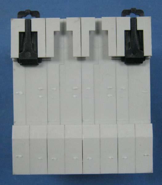
58 age 58 of 60 Report No.: SHA-004 hotos of samples:

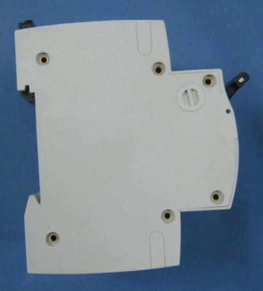
59 age 59 of 60 Report No.: SHA-004 hotos of samples:

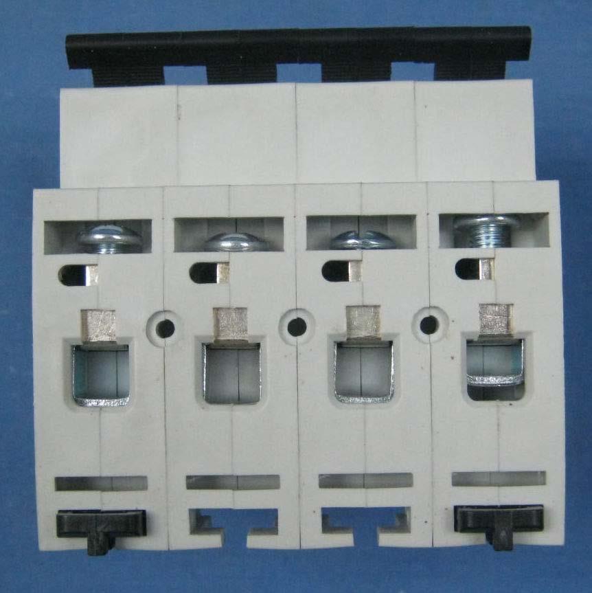
60 age 60 of 60 Report No.: SHA-004 hotos of samples:
TEST REPORT IEC :2002 Circuit-Breakers for overcorrect protection for household and similar installation
 age 1 of 92 R e port ref. No.: C009-CB2012CQC-044407 Test Report issued under the responsibility of: TEST REORT IEC 60 898-1:2002 Circuit-Breakers for overcorrect protection for household and similar installation
Test Report issued under the responsibility of: SHA-001 Date of issue... : Total number of pages... : 292. Report Number...
 D Test Report issued under the responsibility of: TEST REORT Residual current operated circuit-breakers without integral overcurrent protection for household and similar uses (RCCBs) art 1: General rules
Test Report issued under the responsibility of: Report Number...: B Date of issue...: Total number of pages...
 Test Report issued under the responsibility of: TEST REORT Residual current operated circuit-breakers without integral overcurrent protection for household and similar uses (RCCBs) art 1: General rules
TeSys circuit-breakers
 Presentation Thermal-magnetic motor circuit-breakers types GV2, GV and GV7 GV2-ME, GV2-P, GV-ME and GV7-R motor circuit-breakers are -pole thermal-magnetic circuit-breakers specifically designed for the
C120N circuit-breakers B, C and D curves EN 60898/EN 61009: IEC : 10 ka
 C0N circuit-breakers B, C and D curves EN 09/EN 009: 0000 - IEC 097-: 0 ka function # protection of cables against overloads and short-circuits in final distribution # manual control and isolation # earth
Sealing possibility Electrical endurance (ops) Mechanical endurance (ops) Overvoltage category Standards
 Mechanical endurance (ops) Overvoltage category Standards") Miniature circuit breaker ETIMAT 7,7 0.5 Rated voltage Rated current Rated frequency Rated short-circuit capacity Energy limiting class characteristic Build-in width Mounting on the rail 0/00 V AC, max.
Miniature circuit breaker ETIMAT 7,7 0.5 Rated voltage Rated current Rated frequency Rated short-circuit capacity Energy limiting class characteristic Build-in width Mounting on the rail 0/00 V AC, max.
Thermal-Magnetic Circuit Breaker 2210-T2...
 Thermal-Magnetic Circuit Breaker 0-T... Description One, two and three pole thermal-magnetic circuit breakers with trip-free mechanism and toggle actuation (S-type TM CBE to EN 6094/IEC 94). Featuring
5SJ4...-.HG Circuit Breakers to IEC and UL 489
 Siemens AG 009 5SJ...-.HG Circuit Breakers to IEC and UL 89 BETA Low-Voltage Circuit Protection Compliance with industry standards is a must in today's manufacturing environment. Worldwide acceptance is
MCB NB1-63H Miniature Circuit Breaker
 NB-H Miniature Circuit Breaker. General. Function protection of circuits against short-circuit currents, protection of circuits against overload currents, switch, isolation, NB-H circuit-breakers are used
Issued August DATA SHEET. 3VT3 MCCB up to 630 A
 ssued August 9 DATA SHEET VT MCCB up to 6 A Based on Siemens Catalog V 6 8 Circuit breakers Switch disconnectors Technical specifications Specifications Type VT 76-AA6/6/56-AA, VT 76-AA6/6/56-AA Circuit
AC Motor capacitor. Part 1: General Performance, testing and rating Safety requirements Guide for installation and operation
 Test Report issued under the responsibility of: TEST REORT A.C. motor capacitors art 1: General erformance, testing and rating Safety requirements Guide for installation and operation Report Reference
THE DIMENSIONING OF ELECTRICAL CONDUCTORS FOR USE IN "PANEL BOARDS" ADDRESSED TO HAZARDOUS AREAS - PART THREE
 July 04 THE DIMENSIONING OF ELECTRICAL CONDUCTORS FOR USE IN "PANEL BOARDS" ADDRESSED TO HAZARDOUS AREAS - PART THREE In this third part. we want to speak about how important is the correct sizing of the
Magnetic and Hydraulic-Magnetic Circuit Breaker 8340-T...
 Magnetic and Hydraulic-Magnetic Circuit Breaker 830-T... Description ngle, two and three pole magnetic and hydraulic-magnetic circuit breakers with trip-free mechanism and toggle actuation. A choice of
Thermal-Magnetic Circuit Breaker 2210-S2...
 Thermal-Magnetic Circuit Breaker 0-S... Description One, two and three pole thermal-magnetic circuit breakers with trip free mechanism and toggle actuation (S-type TM CBE to EN 60934/IEC 934). Designed
Thermal-Magnetic Circuit Breaker 2210-S2...
 Description One, two and three pole thermal-magnetic circuit breakers with trip free mechanism and toggle actuation (S-type TM CBE to EN 6094/IEC 94). Designed for panel or plug-in mounting. Available
C60N circuit breakers0 B, C and D curves IEC 60898: 6000 A, IEC : 10 ka
 C0N circuit breakers0 B, C and s IEC 0898: 000 A, IEC 097-: 0 ka Function b The circuit-breakers combine the following functions: v protection of circuits against short-circuit currents v protection of
Universal limit switches
 SWITCHES.CROUZET.COM 1 LIMIT SWITCHES 0/016 Universal limit switches 8384 standard 8384 with positive break operation Conformity to standards IEC / EN 60947--1, including Annex K for version with positive
Thermal-Magnetic Circuit Breaker 2210-S2..
 Thermal-Magnetic Circuit Breaker -S.. Description One, two and three pole thermal-magnetic circuit breakers with trip free mechanism and toggle actuation (S-type TM CBE to EN 6094/IEC 94). Designed for
Varius SUMMARY OF MODELS OF HRC FUSE-LINKS
 SUMMARY OF MODELS OF HRC FUSE-LINKS Type PNA000 PHNA000 PNA00 PHNA00 Rated current I n up to A up to 0 A up to A up to 0 A Rated voltage U n AC 00 V, 00 V 90 V 00 V 90 V DC 0 V 0 V 0 V 0 V Fuse-link size
Issued August DATA SHEET. 3VT5 MCCB up to 1600 A
 ssued August 9 DATA SHEET VT5 MCCB up to 0 A Based on Siemens Catalog V 8 Standard circuit breakers Releases Technical specifications Specifications VT5 circuit breakers Switch disconnectors Type Standards
Thermal-Magnetic Circuit Breaker 2210-S2..
 Thermal-Magnetic Circuit Breaker -S.. Description One, two and three pole thermal-magnetic circuit breakers with trip free mechanism and toggle actuation (S-type TM CBE to EN 60934/IEC 934). Designed for
TEST REPORT IEC Photobiological safety of lamps and lamp systems
 age 1 of 20 Test Report issued under the responsibility of: Intertek Testing Services Shenzhen Ltd. TEST REORT hotobiological safety of lamps and lamp systems Report Reference No.... : 140729054GZU-002
LD-LP-LL-LC Rope Safety Switches with reset for emergency stop
 TECHNICA DATASHEET D-P--C Rope Safety Switches with reset for emergency stop Metal or polymer housing, from one or three conduit entries Protection degree IP6 In conformity with EN ISO 13850 contact blocks
Thermal-Magnetic Circuit Breaker 2210-S2..
 Thermal-Magnetic Circuit Breaker -S.. Description One, two and three pole thermal-magnetic circuit breakers with trip-free mechanism and toggle actuation (S-type TM CBE to EN 60934/IEC 934). Designed for
Telemando Reconectadores automáticos compactos
 18 Telemando Reconectadores automáticos compactos Nº de polos IDn (ma) Intensidad (A) Referencia.V.. 2 30 300 40 MT53RA2A040030 198,80 63 MT53RA2A063030 219,70 40 MT53RA2A040300 213,00 63 MT53RA2A063300
ISOCON-6. 24V AC or DC POWERED ISOLATING SIGNAL CONVERTER
 ISOCON-6 24V AC or DC POWERED ISOLATING SIGNAL CONVERTER Whilst every effort has been taken to ensure the accuracy of this document, we accept no responsibility for damage, injury, loss or expense resulting
Photobiological safety of lamps and lamp systems
 Test Report issued under the responsibility of: TEST REORT hotobiological safety of lamps and lamp systems Report Reference No.... : Dialight Optics Lab Request #16119 Date of issue... : 9/22/2016 Total
FAZ tripping characteristics at 30 C: B, C, D to IEC/EN FAZ tripping characteristics at 30 C: R to IEC/EN
 FAZ, AZ High-Capacity Tripping Characteristics Moeller HPL011-001/00 1/07 FAZ tripping characteristics at 0 C: B, C, D to IEC/EN 0 9 FAZ tripping characteristics at 0 C: R to IEC/EN 0 97 t [s] 700 00 100
TEST REPORT IEC Photobiological safety of lamps and lamp systems
 Test Report issued under the responsibility of: TEST REORT hotobiological safety of lamps and lamp systems Report Reference No.... : 17-12-07 Date of issue... : 2017-12-18 Total number of pages... : 19
BETA Protecting. Low-Voltage Fuse Systems. LV HRC fuse links. 3/36 Siemens ET B1 2008
 LV HRC fuse links Overview LV HRC fuses are used for installation systems in non-residential, commercial and industrial buildings as well as in switchboards of power supply companies. They therefore protect
TEST REPORT IEC Photobiological safety of lamps and lamp systems
 TEST REORT hotobiological safety of lamps and lamp systems Report Reference No.... : Date of issue... : Total number of pages... : Testing Laboratory... : Address... : Applicant s name... : Address...
Request Ensure that this Instruction Manual is delivered to the end users and the maintenance manager.
 Request Ensure that this Instruction Manual is delivered to the end users and the maintenance manager. 1 -A - Introduction - Thank for your purchasing MITSUBISHI ELECTRIC MELPRO TM D Series Digital Protection
90 MCB MODULAR CIRCUIT BREAKERS FOR CIRCUIT PROTECTION
 MCB - MTC - MT - MTHP Technical data TYPE MTC MT MTC45 MTC60 MTC100 MT 45 MT 60 Rated current (In) (A) 2-32 6-32 6-32 6-40 1-63 Utilization category A A A A A Rated operational voltage (Ue) (V) 230/400-240/415
UL 1077 DIN Rail Supplementary Protectors
 UL 0 DIN Rail Supplementary Protectors Product Overview UL 0 DIN Rail Supplementary Protectors PRODUCT OVERVIEW Product Overview Standard Features WMZS breaker terminals provide finger and back-of-hand
Photobiological safety of lamps and lamp systems
 age 1 of 27 Test Report issued under the responsibility of: Intertek Testing Services Shenzhen Ltd. Guangzhou Branch TEST REORT IEC 62471 hotobiological safety of lamps and lamp systems Report Reference
90 MCB range Modular circuit breakers for circuit protection
 MCB - MTC - MT - MTHP Technical data TYPE MTC MT MTC45 MTC60 MTC100 MT 45 MT 60 Rated current (In) (A) 2-32 6-32 6-32 6-40 1-63 Utilization category A A A A A Rated operational voltage (Ue) (V) 230 / 400
5SP and 5SY Supplementary Protection UL 1077
 Product Guide 5SP and 5SY Supplementary Protection UL 077 for North merican and International applications usa.siemens.com/5sy Table of contents Certifications, standards, features and description Characteristic
08/072 PKZ2 Motor-Protective Circuit-Breakers Tripping Characteristics
 0/07 PKZ Tripping Characteristics Moeller HPL0-00/00 S-PKZ high-capacity contact module, SEA-PKZ contact module Normal switching duty AC-/00V kw A Rated output of three-phase motors 0...0 Hz. 7..... 0.7
VX25 Enclosure System. Technical documentation PE conductor connection, current carrying capacity
 VX Enclosure System Technical documentation PE conductor connection, current carrying capacity Enclosure system VX Contents Contents. General remarks. Introduction. Notes on the design of the earthing
Siemens AG Miniature Circuit Breakers. Totally Integrated Power SENTRON. Configuration. Edition 10/2014. Manual. siemens.
 Siemens AG 05 Totally Integrated Power SENTRON Configuration Manual Edition 0/0 siemens.com/lowvoltage Siemens AG 05 Siemens AG 05 Introduction 5SL miniature circuit breakers 5SY and 5SP miniature circuit
ISOCON-3 MAINS POWERED ISOLATING SIGNAL CONVERTER
 ISOCON-3 MAINS POWERED ISOLATING SIGNAL CONVERTER CAUTION: This equipment is designed for connection to mains voltages and must be used in accordance with this guide. If it is not, the safety protection
X T O B P 1 6 B C 1 S
 9 Overload Relays XTOB, XTOT May 07 Contents Description Page Overload Relays XTOB, XTOT Selection................ 9 Product Selection.......... 95 Accessories............... 9 Technical Data and Specifications............
This product/component/material was tested to determine the levels of the six hazardous substances in accordance with the standard
 Test Report issued under the responsibility of: CTS Co., Ltd. 501, Samsung Techno-park, 97, Jungbu-daero 448beon-gil, Yeongtong-gu, Suwon-si, Gyeonggido, Korea TEST REPORT Procedures for the determination
Page 2 of 14 Report Ref. No
 age 2 of 14 Summary of testing: Tests performed (name of test and test clause): Clause 6.1, Initial measurements: - MST 01: Visual inspection - 10.2: Maximum power determination - MST 16: Dielectric withstand
To order, specify : Types Protection functions Current surge Asymmetry and loss of phase. Operating principle
 otor protection relays - T - FWIT Since % of -phase motor failures are due to load problems or loss of phase, the CROUZET range of motor protection relays is indispensable! models give motor protection
Film Capacitors. EMI suppression capacitors. Date: June 2018
 Film Capacitors EMI suppression capacitors Date: June 2018 EPCOS AG 2018. Reproduction, publication and dissemination of this publication, enclosures hereto and the information contained therein without
For the electronic measurement of current: DC, AC, pulsed..., with galvanic separation between the primary and the secondary circuit.
 Current Transducer LDSR 0.3-TP/SP1 I P R N = 300 ma For the electronic measurement of current: DC, AC, pulsed..., with galvanic separation between the primary and the secondary circuit. Features Closed
INSTITUTE OF TESTING AND CERTIFICATION (INDIA) PVT.LTD.
 PVT.LTD.") (INDIA) VT.LTD. 60598-1 Requirement Result/Remarks Verdict 2.2 2.3 2.4 2.5 3.2.1 3.2.2 3.2.3 3.2.4 3.2.5 3.2.6 3.2.7 3.2.8 3.2.9 2 Classification of Luminaries Classification according to type of protection
(INDIA) VT.LTD. 60598-1 Requirement Result/Remarks Verdict 2.2 2.3 2.4 2.5 3.2.1 3.2.2 3.2.3 3.2.4 3.2.5 3.2.6 3.2.7 3.2.8 3.2.9 2 Classification of Luminaries Classification according to type of protection
General characteristics, Products
 The Feature Packed line of Manual Motor Protectors Eaton s new XT family of Manual Motor Protectors (MMPs) features a pushbutton or rotary ON/OFF manual disconnect, Class adjustable bimetallic overload
TEST REPORT IEC and/or EN Photobiological safety of lamps and lamp systems
 Test Report issued under the responsibility of: TEST REORT IEC 62471 and/or EN 62471 hotobiological safety of lamps and lamp systems Report Reference No.... : GZES130300236831 Tested by (name + signature)...
3VT4 Molded Case Circuit Breakers up to 1000 A
 VT4 Molded Case Circuit Breakers up to 00 A Catalog Technical nformation VT4 Molded Case Circuit Breakers up to 00 A General data / - Overview Circuit breakers Switch disconnectors / - Selection and ordering
F F FAULT CURRENT Prospective. 1. Introduction. 2. Types of fault conditions
 FAULT CURRENT F F13-13 FAULT CURRENT - Contents 1. Introduction 2. Types of fault conditions 3 fault current must be determined 3.1 Purposes for which of prospective fault current magnitudes are used 3.2
TEST REPORT IEC / EN Photobiological safety of lamps and lamp systems
 age 1 of 22 TEST REORT hotobiological safety of lamps and lamp systems Report Reference No...: 3006889.51-QUA/LI Date of issue...: 2011-03-08 Total number of pages...: Testing Laboratory...: Address...:
M I N I S T R Y O F C O M M U N I C A T I O N S T E L E C O M M U N I C A T I O N S S E C T O R T E C H N I C A L S T A N D A R D F O R
 M I N I S T R Y O F C O M M U N I C A T I O N S T E L E C O M M U N I C A T I O N S S E C T O R T E C H N I C A L S T A N D A R D F O R M A T E R I A L S N O. G 2 0 : 1 0 : 0 0 1 : 1 8 J U M P E R W I
Masterpact. Installation recommendations
 90 Installation recommendations Presentation Functions and characteristics 9 Dimensions and connection 5 Electrical diagrams 8 Operating conditions 92 Installation in switchboard 9 Door interlock catch
TEST CERTIFICATES OR REPORTS ISSUED BY VEIKI-VNL LTD.
 Page 2 of 29 TEST CERTIFICATES OR REPORTS ISSUED BY LTD. Type Test Certificate of Complete Type Test This certificate provides the verification of all the rated characteristics of the equipment as assigned
TEST REPORT IEC Photobiological safety of lamps and lamp systems
 Test Report issued under the responsibility of: TEST REORT hotobiological safety of lamps and lamp systems Report Reference No.... : 4326246.51 Date of issue... : 2016-02-23 Total number of pages... :
BETA Protecting Miniature Circuit Breakers
 Siemens AG 00 / Product overview / High-capacity range 000 A 0000 A 0000 A, high current 0000 A, universal current 000 A ka /0 Comfort range with plug-in terminal / Compact range +N in MW / Additional
H i g h A m p e r a g e 2 5 t o A M P. T y p e I & I I I V e h i c l e P r o t e c t i o n. I P 6 7 W a t e r p r o o f
 H i g h A m p e r a g e 2 5 t o 3 0 0 A M P T y p e I & I I I V e h i c l e P r o t e c t i o n I P 6 7 W a t e r p r o o f I g n i t i o n - P r o t e c t e d S A E & A B Y C C o m p l i a n t L E D T
SolderSleeve Devices Specification For Commercial Wire Splices. Table of Contents
 Page 1 of 15 SolderSleeve Devices Specification For Commercial Wire Splices Table of Contents Chapter Pages 1.0 General Requirements 1.1 Design of the Electrical Connection-Reminder Concerning The Approval
Amphenol. Amphenol-Tuchel Electronics GmbH. Circular Connectors C 091 A/B/D Series
 Amphenol Amphenol-Tuchel Electronics GmbH Circular Connectors C 09 A/B/D Series The Company Amphenol-Tuchel Electronics GmbH is a member of the USA based Amphenol Corporation. With our own global presence
FL ballasts Electronic fixed output. PC TC PRO sr 1/2x11 42 W PC PRO compact
 FL ballasts EL HE PC TC PRO sr 1/2x11 42 W PC PRO compact Product description CELMA Energy Efficiency Index A2 BAT / A2 T Nominal life-time up to 50,000 h (at ta 50 C with a failure rate max. 0.2 % per
Overload Relays. SIRIUS 3RU1 Thermal Overload Relays. 3RU11 for standard applications. 5/46 Siemens LV 1 AO 2011
 SIRIUS 3RU1 Thermal Overview 1 2 7 3 4 6 "Increased safety" type of EEx e according to ATEX directive 94/9/EC The 3RU11 thermal overload relays are suitable for the overload of explosion-proof motors with
Report No 247/ This Report consists of 41 pages
 Test Report Report No 247/ 7340511 This Report consists of 41 pages Client Electrical Safety Council 18 Buckingham Gate London SW1E 6LB Authority & date BSI Estimate Acceptance No 0000191154 dated 12 March
Amphenol C 091 A/B/D. Circular Connectors. Amphenol-Tuchel Electronics GmbH
 Amphenol C 091 A/B/D Circular Connectors Amphenol-Tuchel Electronics GmbH General information These connectors are designed and produced in conformity with the low-voltage directive (/3/EWG) respectively
Photobiological safety of lamps and lamp systems
 Test Report issued under the responsibility of: age 1 of 14 TEST REORT hotobiological safety of lamps and lamp systems Report Reference No.... : GZES111000681631 Tested by (name + signature)... : Bica
General characteristics
 General characteristics This range of insulators and partition bushings provides for connecting and supporting low- and medium-voltage electrical equipment. - Their purpose is to provide electrical and
Product Data Sheet PD-0037-B
 Product Data Sheet PD-0037-B 3M Shielded Compact Ribbon (SCR) Connector 3M Shielded Compact Ribbon (SCR) Boardmount Right Angle 36110-2220 XX 3 Electronic Solutions Division Page: 1 of 12 Table of Contents
16 Appendix 16 Electrical Research Association Report
 Guide to the Wiring Regulations 16 Appendix 16 Electrical Research Association Report (ERA) report on armoured cables with external CPCs The attached report was commissioned by the ECA and is copyright
TEST REPORT REPORT NO.: QAV PAGE: 1 OF 31
 QAV Technologies Sdn. Bhd. (616788-U) 116, Lintang Kampung Jawa, NFIZ 3, Taman erindustrian Bayan Lepas, MK 12, 11900 enang, Malaysia. Tel No : 604 643 8317 Fax No : 604 643 8597 Email : qavtech@qavtech.com
S R O T C U D IN & MYRRA
 TRANSFORMERS & INDUCTORS MYRRA...Of course! TECHNICAL INFORMATION RATED PRIMARY OLTAGE () This is the supply assigned to the transformer by the manufacturer. RATED SECONDARY OLTAGE () This is the secondary
CONNECTORS, ELECTRICAL, RECTANGULAR, MICROMINIATURE, NON-REMOVABLE GAUGE 26 PCB PIN CONTACTS BASED ON TYPE 8MCG
 Page 1 of 27 CONNECTORS, ELECTRICAL, RECTANGULAR, MICROMINIATURE, NON-REMOVABLE GAUGE 26 PCB PIN CONTACTS BASED ON TYPE 8MCG Issue 6 June 2018 Document Custodian: European Space Agency see https://escies.org
ATyS Automatic and remotely operated transfer switches from 125 to 3200 A
 atys-p_001_b atys_d_001_a_1_cat ATyS p I-0-II 4P ATyS d I-0-II 4P Function The ATyS are three-phase motorised transfer switches with positive break indication. They enable the on load transfer of two three-phase
TEST REPORT IEC and/or EN Photobiological safety of lamps and lamp systems
 Test Report issued under the responsibility of: TEST REORT and/or EN 62471 hotobiological safety of lamps and lamp systems Report Reference No.... : GZES160200176431 Tested by (name + signature)... : Jack
16 Input AC Block I/O Module
 6 Input AC Module Cat. No. 79-6A0 Series B Installation Mount the block I/O module in a vertical (recommended) or horizontal position. Allow sufficient room around the block for cooling air flow through
Photobiological safety of lamps and lamp systems
 Test Report issued under the responsibility of: TEST REORT hotobiological safety of lamps and lamp systems Report Reference No.... : GZES130300220831 Date of issue... : 2013-04-07 Total number of pages...
CGS ALUMINUM ELECTROLYTIC CAPACITORS
 CGS ALUMINUM ELECTROLYTIC CAPACITORS EXTREME APPLICATON HIGHLIGHTS APPLICATION Capacitance 50-500,000µF U.P.S Systems Voltage 15 to 500 WVDc Inverters/P.C.U.s. -10%, + 20% Tolerance and Motor Special Controls
TECHNICAL INFORMATION
 TECHNICAL INFORMATION RATED PRIMARY OLTAGE () This is the supply assigned to the transformer by the manufacturer. RATED SECONDARY OLTAGE () This is the secondary output assigned to the transformer when
CDS. high density spring connection
 CDS high density spring connection DENSTY STANDARD 1A CDS DENSTY A A spring connection CDS Series The originality of multipole connectors represents one of the core values of LE, a leading company in this
Periodic Inspection and Testing of Electrical Installations Sample Test ( ) Version 1.3 July 2018
 Version 1.3 July 2018") Periodic Inspection and Testing of Electrical Installations Sample Test (2391-051) Version 1.3 July 2018 Sample Questions Version and date Change detail Section 1.3 July 2018 Modified questions/answers
Periodic Inspection and Testing of Electrical Installations Sample Test (2391-051) Version 1.3 July 2018 Sample Questions Version and date Change detail Section 1.3 July 2018 Modified questions/answers
High-ohmic/high-voltage resistors
 FEATURES These resistors meet the safety requirements of: UL1676 (range 510 kω to 11 MΩ) EN60065 BS60065 (U.K.) NFC 92-130 (France) VDE 0860 (Germany) High pulse loading capability Small size. APPLICATIONS
Impedance relay and protection assemblies
 RXZK 21H, 22H, 23H 509 006-BEN Page 1 Issued June 1999 Changed since July 1998 Data subject to change without notice (SE970175) (SE970184) Features Micro-processor based impedance relay with R and X settings
LED light engine / OLED LED compact. Uengine DLE G2 integrated ADV
 Uengine DLE G2 integrated ADV uengine DLE Product description Module with integrated electronics For downlights Light engine operating with 23 V AC Luminous flux range from 1,24 2,43 lm High system efficacy
DATA SHEET. 88 Longteng Road, Economic & Technical Development Zone, Kunshan, Jiangsu, China
 DATA SHEET Product Name Complete Pb-Free Thick Film Chip Resistors Part Name PF Series Uniroyal Electronics Global Co., Ltd. 88 Longteng Road, Economic & Technical Development Zone, Kunshan, Jiangsu, China
40 CD RANGE FLUSH-MOUNTING DISTRIBUTION BOARDS AND ENCLOSURES
 DISTRIBUTION BOARDS FLUSH-MOUNTING DISTRIBUTION BOARDS GWTEST SOFTWARE (see page 322) Complementary system items Ordinary installation - protected flush mounting DISTRIBUTION / JUNCTION Protection devices...
Alternating Current (AC): Alternating Current is electric current that reverses directions at regular intervals.
: Alternating Current is electric current that reverses directions at regular intervals.") Glossary Alternating Current (AC): Alternating Current is electric current that reverses directions at regular intervals. American National Standards Institute (ANSI): American National Standards Institute
Glossary Alternating Current (AC): Alternating Current is electric current that reverses directions at regular intervals. American National Standards Institute (ANSI): American National Standards Institute
Non-Contact Safety Systems CMS
 Selection table for non-contact safety system // Evaluation units Connection Desi Read head contact assembly Assured switch-on distance S ao [mm] Assured switch-on distance S ar [mm] Number of outputs
PHASED OUT. LED light engines LED linear / area. Module CLE Quadrant G2 ADV Modules CLE ADVANCED
 Product description Ideal for round shaped and flat ceiling and pendant luminaires THE solution to realise XXL luminaires For uniform illumination of prestige areas or rooms designed to impress High Output
Interference suppression film capacitors MKP 336 1
 MKP RADIAL POTTED TYPE PITCH /15/22.5/27.5 mm l b h lt P d t CBA196 Fig.1 Simplified outlines. FEATURES to 27.5 mm lead pitch Supplied loose in box and taped on reel Consists of a low-inductive wound cell
WW12C, WW08C, WW06C, WW04C, WW02C. Low ohm chip resistors ( power ) Size 1206, 0805, 0603, 0402, 0201
 Size 1206, 0805, 0603, 0402, 0201") WW12C, WW08C, WW06C, WW04C, WW02C ±5%, ±1%, ±0.5% Low ohm chip resistors ( power ) Size 1206, 0805, 0603, 0402, 0201 *Contents in this sheet are subject to change without prior notice. Page 1 of 8 ASC_WWxxC_V05
WW12C, WW08C, WW06C, WW04C, WW02C ±5%, ±1%, ±0.5% Low ohm chip resistors ( power ) Size 1206, 0805, 0603, 0402, 0201 *Contents in this sheet are subject to change without prior notice. Page 1 of 8 ASC_WWxxC_V05
Product Data Sheet PD-0053-A
 Product Data Sheet PD-0053-A 3M Mini D Ribbon (MDR) Connector MDR Surface Mount 102XX-1210 XE 102XX-1S10 XE Page: 1 of 11 Table of Contents 1.0 SCOPE...2 2.0 PRODUCT TESTED...2 3.0 GENERAL CONDITIONS...2
Installation guide 862 MIT / MIR
 Installation guide 862 MIT / MIR in combination with: 864 MTT or 863 MRT or (dual) spot element November 2005 Part no. 4416.232_Rev3 Enraf BV PO Box 812 2600 AV Delft Netherlands Tel. : +31 15 2701 100
FEATURES APPLICATIONS DESCRIPTION QUICK REFERENCE DATA. PILKOR components
 FEATURES Excellent anti-surge characteristics Stable characteristics to moisture resistance even in high resistance range. Good replacement for ceramic plate resistors. APPLICATIONS Telecommunication Industrial
WK25V, WK20V, WK12V, WK08V, WK06V. Thick Film High Voltage Chip Resistors. Size 2512, 2010,1206, 0805, 0603
 WK25V, WK20V, WK12V, WK08V, WK06V ±5%, ±2%, ±1%, ±0.5% Thick Film High Voltage Chip Resistors Size 2512, 2010,1206, 0805, 0603 *Contents in this sheet are subject to change without prior notice. Page 1
GESELLSCHAFT FÜR ELEKTRISCHE HOCHLEISTUNGSPRÜFUNGEN Mitglied der Short-Circuit-Testing Liaison (STL) Test Report
 Test Report") Mitglied der Short-Circuit-Testing Liaison (STL) Test Report Report-No.: 9725Fr Copy-No.: 00 Contents: 16Sheets Equipment under Test: Manufacturer: Client: Metal-enclosed, single-pole metal-clad and SF
Mitglied der Short-Circuit-Testing Liaison (STL) Test Report Report-No.: 9725Fr Copy-No.: 00 Contents: 16Sheets Equipment under Test: Manufacturer: Client: Metal-enclosed, single-pole metal-clad and SF
Instruction. Vacuum Circuit Breaker Operator Module. Type 3AH 4.16kV to 38kV. Power Transmission & Distribution
 Instruction 0001-22-2--00 Vacuum Circuit Breaker Operator Module Type 3AH 4.16kV to 38kV Power Transmission & Distribution Hazardous voltages and high-speed moving parts. Will cause death, serious injury
MR medium rating busbar
 technical information General features MR is fully compliant with S EN 0-, specifically, the rated current of the Zucchini busbar trunking systems is always rated at the average ambient temperature of
Ref: HLSR 16-PW; HLSR 32-PW; HLSR 40-PW-000; HLSR 50-PW-000,
 Digital Current Transducer HLSR-PW series I P N = 16... 50 A Ref: HLSR 16-PW; HLSR 32-PW; HLSR 40-PW-000; HLSR 50-PW-000, Bitstream output from on onboard Sigma Delta modulator. For the electronic measurement