Geotechnical Investigation
|
|
|
- Kristian Chandler
- 6 years ago
- Views:
Transcription

1 Geotechnical Investigation Veterans Parkway Bridge Approaches Investigation Savannah, Georgia July 20, 2015 Terracon Project No. ES Prepared for: Chatham County Engineering Department Savannah, Georgia Prepared by: Terracon Consultants, Inc. Savannah, Georgia

2 July 20, 2015 Chatham County Engineering Department 124 Bull Street, Suite 430 Savannah, Georgia Attn: Re: Nathaniel Panther P.E. P: (912) F: (912) E: Geotechnical Investigation Veterans Parkway Bridge Approaches Investigation Chatham County, Georgia Terracon Project No.: ES Dear Mr. Panther: Terracon Consultants, Inc. (Terracon) has completed the Geotechnical Engineering Investigation for the above-referenced project. The services were performed in general accordance with our proposal No. PES dated February 16, This report presents the findings of the subsurface exploration and provides geotechnical recommendations for the design and construction of the project. We appreciate the opportunity to be of service to you. Should you have any questions concerning this report, or if we may be of further service, please contact us. Sincerely, Terracon Consultants, Inc. Yanbo Huang, Ph.D., E.I.T. Staff Geotechnical Engineer Guoming Lin, Ph.D., P.E. Senior Principal cc: 1 Client (PDF) 1 File Terracon Consultants, Inc Rowland Avenue Savannah, Georgia P (912) F (912) terracon.com/savannah
3 TABLE OF CONTENTS Section Page EXECUTIVE SUMMARY... i 1.0 INTRODUCTION PROJECT INFORMATION Project Description Site Location and Description SUBSURFACE CONDITIONS Typical Profile Groundwater RECOMMENDATIONS FOR DESIGN AND CONSTRUCTION Geotechnical Considerations Recommendation for Remediation GENERAL COMMENTS... 6 Responsive Resourceful Reliable
4 APPENDICE APPENDIX A: Exhibit A-1 Exhibit A-2 Exhibit A-3 Exhibit A-4 Exhibit A-5 Exhibit A-6 Exhibit A-7 FIELD EXPLORATION Site Location Map Exploration Location Plan Field Exploration Description CPT Sounding Cross Section CPT Sounding Logs SPT Boring Cross Section SPT Boring Logs APPENDIX B: Exhibit B-1 Exhibit B-2 Exhibit B-3 SUPPORTING INFORMATION General Notes Unified Soil Classification System CPT-based Soil Classification APPENDIX C: Exhibit C-1 Exhibit C-2 Exhibit C-3 Exhibit C-4 Exhibit C-5 SUPPORTING INFORMATION Differential Settlement Survey Photos of Pavement Cores Information of Bridge Design Information of Approach Slab Design Information of Embankment Fill Responsive Resourceful Reliable
5 Geotechnical Investigation Veterans Parkway Bridges Approaches Investigation Savannah, Georgia July 20, 2015 Terracon Project No. ES EXECUTIVE SUMMARY This report presents the findings of our Geotechnical Engineering Investigation for the existing Veterans Parkway Little Ogeechee River Bridges Approaches Investigation located on Veterans Parkway in Chatham County, Georgia. The investigation included a field exploration program and engineering evaluation of the subsurface conditions and repair recommendations. Based on the results of the subsurface exploration and analyses, the following geotechnical considerations were identified: The project includes two bridges and four approach slabs. The subsurface conditions of the site are relatively consistent at each end of the bridge. At the south end (begin bridges), the soils in the upper 40 feet are loose to medium dense silty sands to sands with silt interbedded with sandy clays, underlain by medium stiff to very stiff silty / sandy clays with thickness of 33 feet. At the north end (end bridges), the soil in the upper 12 to 13 feet are loose to medium dense silty sands, underlain by a layer of sandy clays with thickness of approximately 8 feet. The groundwater was encountered at approximately 30 feet below the existing ground surface (BGS) at the south end of bridges (begin bridges) and 16.5 to 25 feet BGS at the north end (end bridges) based on CPT soundings and SPT borings. The expansion joints between the approach slabs and the bridge decks were supposed to be one inch wide according to the design plan but were currently at 2.5 to 3 inches wide. In addition, there were differential settlements of 0.25 to one inch between the approach slabs and the bridge decks at the end bents. In general, the differential settlements were larger at the north ends (end bridges) than at the south ends (begin bridges). Both the approach slabs and the bridge decks at the end bents are supported on the same pile foundations, so the mechanisms of joint widening and differential settlements were rather perplexing. There are gaps (voids) as large as three inches beneath the approach slabs to the top of the subgrade. Most likely the slab movements were initially caused by the settlements of the embankment fill. The voids beneath the slabs have reduced the frictional resistance and the forces from the traffic may have caused the slabs to slide. The differential settlements may be attributable to the structural damage at bearing supports by repeated traffic loads. We explored the repair options with several contractors and a GDOT engineer and would recommend the following two repair options. The first option, commonly referred as mud jacking, will mainly involve using grouting to densify the loose embankment fill in the upper 10 feet, filling the gaps beneath the slabs and lifting up the slabs. The second Responsive Resourceful Reliable i
6 Geotechnical Investigation Veterans Parkway Bridges Approaches Investigation Savannah, Georgia July 20, 2015 Terracon Project No. ES option is to demolish the existing approach slabs and reconstruct new slabs after necessary subgrade compaction and repair of bearing supports. This summary should be used in conjunction with the entire report for design purposes. It should be recognized that details were not included or fully developed in this section, and the report must be read in its entirety for a comprehensive understanding of the findings and recommendations contained herein. The section titled GENERAL COMMENTS should be read for an understanding of the report s limitations. Responsive Resourceful Reliable ii
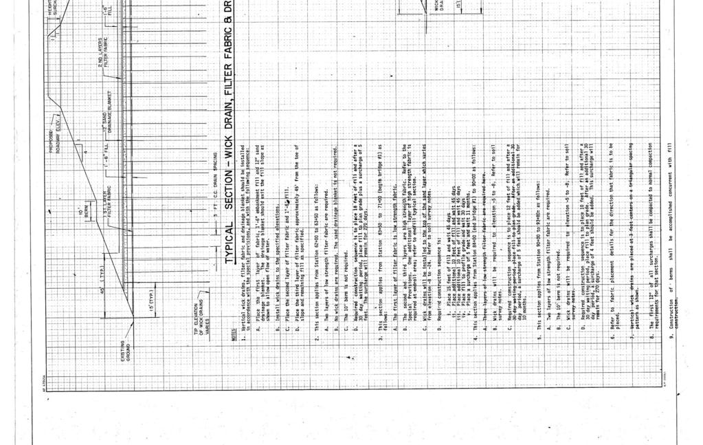
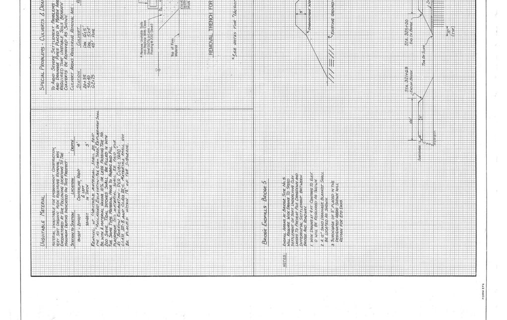
7 GEOTECHNICAL INVESTIGATION Veterans Parkway Bridges Approaches Investigation Savannah, Georgia Terracon Project No. ES July 20, INTRODUCTION Terracon has completed the Geotechnical Engineering Investigation for the existing Veterans Parkway Little Ogeechee River Bridge Approaches located on Veterans Parkway in Savannah, Georgia. The investigation included a field exploration program and engineering evaluation of the subsurface conditions and foundation recommendations. The field exploration program consisted of two (2) cone penetration test (CPT) soundings to a maximum depth of about 73 feet below the existing ground surface (BGS), and two (2) standard penetration test (SPT) borings to a maximum depth of about 80 feet BGS. The CPT sounding and SPT boring logs along with a site location map and exploration location plan are included in Appendix A of this report. The purpose of this study is to provide subsurface information and geotechnical engineering recommendations relative to: subsurface soil conditions Differential Settlement Investigation groundwater conditions Remediation recommendation for the Differential Settlement 2.0 PROJECT INFORMATION 2.1 Project Description The construction of the bridges was completed in The south end (begin bridges) has at least 35 feet of fills and the north end (end bridges) has at least 12 feet of fills. At both ends, 5 feet of surcharge was placed with loading time of 10 to 11 months and both the filter fabric and wick drains were used during the embankment construction. Item Proposed Improvements Finished floor elevation Description The repair of widened expansion joints and differential settlement at bridge approaches. South end (begin bridges): feet. North end (end bridges): feet. Responsive Resourceful Reliable 1
8 Geotechnical Investigation Veterans Parkway Bridges Approaches Investigation Savannah, Georgia July 20, 2015 Terracon Project No. ES Item Design Traffic Data Maximum allowable settlement ADT = 16, 800 (1990) ADT = 28, 600 (2010) Design speed = 60 mile per hour Trucks = 5%. Total settlement: 1 inch (assumed). Description Differential settlement: ½ inches between approach slabs and bridge decks (assumed). 2.2 Site Location and Description Location Item Current ground cover and access conditions Existing topography Description The site is located on Veterans Parkway over the Little Ogeechee River in Chatham County, Georgia. Latitude: , Longitude: Existing road with reinforced concrete approach slabs connecting the asphalt pavement and bridge decks. Relatively level. Should any of the above information or assumptions be inconsistent with the planned construction, Terracon should be informed so that modifications to this report can be made as necessary. 3.0 SUBSURFACE CONDITIONS 3.1 Typical Profile Based on the results of the field exploration, the subsurface conditions at the project site are relatively consistent at each end of the bridges and can be generalized as follows: Description Subsurface Conditions at South End of Bridges (Begin Bridges) Approximate Depth to Bottom of Stratum (feet, BGS) Pavement 1.5 Material Encountered 10 to 11 inches concrete, followed by 2 to 3 inches voids and 2.5 to 5 inches asphalt or piece of concrete. Equivalent SPT - N 60 Stratum 1 10 to 15 Loose silty sands to sands with silt 4 to 10 Responsive Resourceful Reliable 2
9 Geotechnical Investigation Veterans Parkway Bridges Approaches Investigation Savannah, Georgia July 20, 2015 Terracon Project No. ES Description Approximate Depth to Bottom of Stratum (feet, BGS) Stratum 2 40 Stratum 3 71 to 73 Material Encountered Medium dense to dense silty sands interbedded with sandy clays Medium stiff to very stiff silty / sandy clays Equivalent SPT - N to 35 5 to 22 Stratum 4 80, termination of SPT borings Hard sandy clays 30 to 50+ Description Subsurface Conditions at North End of Bridges (End Bridges) Approximate Depth to Bottom of Stratum (feet, BGS) Pavement 1.5 Material Encountered 10 to 11 inches concrete, followed by 2.5 inches voids and 4 inches asphalt. Equivalent SPT - N 60 Stratum 1 12 to 13 Medium dense silty sands. 10 to 30 Stratum 2 20 to 21 Stiff to very stiff sandy clays 8 to 12 Stratum 3 25 Medium dense silty sands 15 to 30 Stratum 4 33 to 34 Soft to stiff silty/sandy clays 4 to 14 Stratum 5 67 to 70 Medium dense to very dense silty sands interbedded with sandy clays 20 to 50+ Stratum 6 80, termination of SPT borings Very stiff to hard sandy clays 29 to 50+ Details of the subsurface conditions encountered at each boring location are presented on the individual CPT sounding and SPT boring logs in Appendix A of this report. Stratification boundaries on the logs represent the approximate depth of changes in soil types; the transition between materials may be gradual. 3.2 Groundwater Groundwater was measured at approximately 30 feet BGS at the south end of bridges (begin bridges) and 16.5 to 25 feet BGS at the north end (end bridges) during the field exploration. It should be noted that groundwater levels tend to fluctuate with seasonal and climatic variations, as well as with construction activities. As such, the possibility of groundwater level fluctuations should be considered when developing the design and construction plans for the project. The groundwater table should be checked prior to construction to assess its effect on site work and other construction activities. Responsive Resourceful Reliable 3
10 Geotechnical Investigation Veterans Parkway Bridges Approaches Investigation Savannah, Georgia July 20, 2015 Terracon Project No. ES RECOMMENDATIONS FOR DESIGN AND CONSTRUCTION 4.1 Geotechnical Considerations The subsurface conditions at this site are considered relatively consistent at each end of bridges. The generalized soil profile is presented in Section 3.1. For the approach slabs at the south end of bridges (begin bridges), the expansion joints between approach slabs and bridge decks have been widen from 1 inch to 2.5~3 inches and the differential settlements at these joints are less than 0.25 inch. From the coring results as shown in Appendix C, about 2 to 3 inches of voids were found right below the slabs. The subgrade materials below the voids were approximately 5 inches asphalt or 2.5 inches piece of concrete. For the approach slabs at the north end of bridges (end bridges), the expansion joints between approach slabs and bridge decks also have been widen from 1 inch to 2.5~3 inches but the differential settlements at these joints are as high as 0.5 to one inch. From the coring results as shown in Appendix C, approximately 2.5 inches of voids were found right below the slab and below the voids, it is followed by approximately 4 inches asphalt. In addition, signs of erosion were noted found at the bridge abutment as shown in Appendix C. Since both the approach slabs and the bridge deck at the end bents are supported on same piled foundations, the mechanisms of the differential settlements are rather perplexing. We reviewed all the available design details of the bridges, approach slabs and embankment. We also discussed the problem of differential settlement at the expansion joints between approach slab and bridge deck with local Georgia DOT engineer. From our GDOT engineer and local contractors, we learned the problem of widened joints and differential settlements is a common occurrence for bridges in the area with high embankment fill over weak soils. The approach slab movements were mostly likely caused initially by consolidation settlement of the embankments. The embankments are underlain by one or more layers of relatively soft clays and the weight of the embankment fill has caused the soft clays to consolidate and settle. The fact the voids beneath the slabs were only 2.5 to 3 inches for the last 20 years suggests the initial ground improvement measures, wick drain, surcharge and waiting time, were largely effective. Without these special measures, the settlements would have been much larger. The soft clays are relatively deep, at depths of 45 to 55 feet at C1 and 25 to 30 feet at C2. It is likely that these soft clay layers would undergo additional consolidation and cause additional settlements. However, the settlements in the next 20 years should be considerably smaller than 2 inches (mostly likely less than 1 inch). As such, we believe the risk of additional settlement would not justify the expense to treat the deep clay layers even though the deep clay layers were considered the root cause of the slab problems. Responsive Resourceful Reliable 4
11 Geotechnical Investigation Veterans Parkway Bridges Approaches Investigation Savannah, Georgia July 20, 2015 Terracon Project No. ES The investigation also revealed that the embankment fill in the upper 10 feet were relatively loose. This may have been caused by deep consolidation settlements and/or inadequate compaction during the embankment construction. It is very likely that the loose embankment fills have contributed to the embankment settlements and formation of the voids beneath the approach slabs. We recommend the embankment subgrade in the upper ten feet be densified as part of the slab repair work. The formation of the voids beneath the slabs resulted in reduction of frictional resistance of the approach slabs. The widening of the expansion joints at the end bents was most likely caused by lateral force exerted by the traveling vehicles. We observed the overall bridge for control and expansion joints and concluded the widening of the expansion joints were unlikely caused by thermal expansion of the bridge structure. Based on discussions with GDOT engineer and other local experienced bridge contractors, the differential settlements between the approach slab and the deck at end bents were likely caused by damage/wearing of the supports from the repeated traffic. 4.2 Recommendation for Repair With the above understandings of the causes of the problem, we discussed the repair options with GDOT engineer and several specialty contractors. Embankment settlements are considered the cause of the slab movements. Embankment settlements were caused primarily by the consolidation settlement of the deep foundation and likely aided by the compression of the loose embankment fill at the upper 10 feet. If a one-time and permanent solution is required to repair the slab, we would recommend grouting be used to improve the deep soft clays as well as the loose embankment fill in the upper 10 feet. However, over a period of 20 years, the embankments have settled up to three inches. Based on the soil consolidation theory and our experience with the soils in this area, we anticipate the embankment will undergo additional settlements but the magnitude of the settlement for the next 20 years should be less than 2 inches and most likely less than one inch. As such, the cost of treating the deep clays may not justify the cost. We recommend the loose sands in the upper 10 feet be improved as part of the repair. We recommend two repair options for the approach slab. The first option, commonly referred as mud jacking, will mainly involve using grouting to densify the loose embankment fill in the upper 10 feet, filling the gaps beneath the slabs and lifting up the slabs. The second option is to demolish the existing approach slabs and reconstruct new slabs after necessary subgrade compaction and repair of bearing supports. Grouting work is typically performed by an experienced specialty contractor. The specialty contractor should develop detailed work plan to achieve the required densification, filling and leveling of the approach slab. The contractor should choose the grouting method (jet grouting, compaction ground or chemical grouting) that is suited for the soil conditions and intended Responsive Resourceful Reliable 5
12 Geotechnical Investigation Veterans Parkway Bridges Approaches Investigation Savannah, Georgia July 20, 2015 Terracon Project No. ES repair. It is very likely that the grouting option would not able to move the slabs lateral to narrow the joints. Also based on the experience of the GDOT engineer Mr. Michael Garner, the mud jacking (grouting) option may not offer a permanent fix but should be attempted as the first option. For the reconstruction option, the slab should be demolished and the subgrade in the upper 10 feet should be improved. The method of improvement may include grouting, stone columns or excavation and recompaction. The new approach slabs should be poured after necessary structural repair of the slab support. The new slab supports should be constructed in accordance with the current GDOT standard details and specifications as shown in Exhibit C-4-3 in Appendix C. The contractor proposing on the repair work should engage a bridge design engineer to develop the repair details. Regardless the repair option selected, the repair should also include measures to prevent erosion of the subgrade soils. The expansion joints should include proper sealant to minimize infiltration of water into the subgrade. 5.0 GENERAL COMMENTS Terracon should be consulted to review the final design plans and specifications so comments can be made regarding interpretation and implementation of our geotechnical recommendations in the project design and specifications. Terracon should also be retained to provide observation and testing services during grading, excavation, foundation construction and other earth-related construction phases of the project. The analyses and recommendations presented in this report are based upon the data obtained from the explorations performed at the indicated locations and from other information discussed in this report. This report does not reflect variations that may occur between exploration locations, across the site, or may be caused due to the modifying effects of construction or weather. Bear in mind that the nature and extent of such variations may not become evident until construction has started or until construction activities have ceased. If variations do appear, Terracon should be notified immediately so that further evaluation and supplemental recommendations can be provided. The scope of services for this project does not include either specifically or by implication any environmental or biological (e.g., mold, fungi, and bacteria) assessment of the site or identification or prevention of pollutants, hazardous materials or hazardous conditions. If the owner is concerned about the potential for such contamination or pollution, please advise so that additional studies may be undertaken. This report has been prepared for the exclusive use of our client for specific application to the project and site discussed, and has been prepared in accordance with generally accepted Responsive Resourceful Reliable 6
13 Geotechnical Investigation Veterans Parkway Bridges Approaches Investigation Savannah, Georgia July 20, 2015 Terracon Project No. ES geotechnical engineering practices. No warranties, either expressed or implied, are intended or made. Site safety, excavation support and dewatering requirements are the responsibility of others. In the event that changes in the nature, design, or location of the project as outlined in this report are planned, the conclusions and recommendations contained in this report shall not be considered valid unless Terracon reviews the changes, and then either verifies or modifies the conclusions of this report in writing. Responsive Resourceful Reliable 7
14 APPENDIX A FIELD EXPLORATION Exhibit A-1 Exhibit A-2 Exhibit A-3 Exhibit A-4 Exhibit A-5 Exhibit A-6 Exhibit A-7 Site Location Map Exploration Location Plan Field Exploration Description CPT Cross Section CPT Logs SPT Cross Section SPT Logs
 629 4000 Fax (912) 629 4001 Veterans Parkway Bridges Approaches Investigation Veterans Parkway Chatham County,")
15 N SITE Image Courtesy of Google Earth Project Manager: YH Project No. ES S I T E L O C A T I O N M A P Exhibit: Drawn by: Checked by: Approved by: YH GL GL Scale: N.T.S. File Name: ES A1 Date: Rowland Avenue Savannah, Georgia Phone (912) Fax (912) Veterans Parkway Bridges Approaches Investigation Veterans Parkway Chatham County, Georgia A-1-1

16 N Image Courtesy of Google Earth Project Manager: YH Project No. ES S I T E H I S T O R I C A L V I E W, 2 / Exhibit: Drawn by: Checked by: Approved by: YH GL GL Scale: N.T.S. File Name: ES A2 Date: Rowland Avenue Savannah, Georgia Phone (912) Fax (912) Veterans Parkway Bridges Approaches Investigation Veterans Parkway Chatham County, Georgia A-1-2

17 N Image Courtesy of Google Earth Project Manager: YH Project No. ES SITE HISTORICAL VIEW, 2 / 1995 Exhibit: Drawn by: Checked by: Approved by: YH GL GL Scale: N.T.S. File Name: ES A2 Date: Rowland Avenue Savannah, Georgia Phone (912) Fax (912) Veterans Parkway Bridges Approaches Investigation Veterans Parkway Chatham County, Georgia A-1-3

18 N Image Courtesy of Google Earth Project Manager: YH Project No. ES SITE HISTORICAL VIEW, 2 / 1999 Exhibit: Drawn by: Checked by: Approved by: YH GL GL Scale: N.T.S. File Name: ES A2 Date: Rowland Avenue Savannah, Georgia Phone (912) Fax (912) Veterans Parkway Bridges Approaches Investigation Veterans Parkway Chatham County, Georgia A-1-4

19 N B1 End Bridges C2 Left Bridge Right Bridge B2 LEGEND CPT Soundings Image Courtesy of Google Earth C1 Begin Bridges SPT Borings NOTES: ALL EXPLORATION LOCATIONS WERE LOCATED IN THE FIELD USING A GPS UNIT AND/OR SITE LANDMARKS. EXPLORATION LOCATIONS SHOULD BE CONSIDERED APPROXIMATE. DIAGRAM IS FOR GENERAL LOCATION ONLY; NOT INTENDED FOR CONSTRUCTION PURPOSES. Project Manager: Drawn by: Checked by: Approved by: YH YH GL GL Project No. ES Scale: N.T.S. File Name: ES A2 Date: Rowland Avenue Savannah, Georgia Phone (912) Fax (912) E X P L O R A T I O N L O C A T I O N P L A N Veterans Parkway Bridges Approaches Investigation Veterans Parkway Chatham County, Georgia Exhibit: A-2
 borings and Cone Penetration Test (CPT) soundings are determined by Terracon based on the proposed development")

20 Geotechnical Engineering Investigation Veterans Parkway Bridges Approaches Investigation Savannah, Georgia April 13, 2015 Terracon Project No.ES Field Exploration Description The locations of Standard Penetration Test (SPT) borings and Cone Penetration Test (CPT) soundings are determined by Terracon based on the proposed development and were located in the field using hand-held GPS units and in reference to existing features. These locations are shown in the Exploration Location Plan and should be considered approximate. Standard Penetration Testing The SPT borings were performed in accordance with ASTM D1586 with an truck-mounted Acker drilling rig using mud rotatory drilling techniques. Samples of the soil encountered in the borings were obtained using splitbarrel sampling procedures. In the split barrel sampling procedure, the number of blows required to advance a standard 2-inch O.D. split barrel sampler the last 12 inches of the typical total 18-inch penetration by means of a 140-pound hammer with a free fall of 30 inches, is the standard penetration resistance value (SPT-N). This value is used to estimate the in situ relative density of cohesionless soils and consistency of cohesive soils. A rope and cathead hammer was used to advance the split-barrel sampler in the borings performed on this site. Cone Penetration Testing The CPT hydraulically pushes an instrumented cone through the soil while nearly continuous readings are recorded to a portable computer. The cone is equipped with electronic load cells to measure tip resistance and sleeve resistance and a pressure transducer to measure the generated ambient pore pressure. The face of the cone has an apex angle of 60 and an area of 10 cm 2. Digital data representing the tip resistance, friction resistance, pore water pressure, and probe inclination angle are recorded about every 2 centimeters while advancing through the ground at a rate between 1½ and 2½ centimeters per second. These measurements are correlated to various soil properties used for geotechnical design. No soil samples are gathered through this subsurface investigation technique. CPT testing is conducted in general accordance with ASTM D5778 "Standard Test Method for Performing Electronic Friction Cone and Piezocone Penetration Testing of Soils." Source: FHWA NHI Upon completion, the data collected were analyzed and processed by the project engineer. Source: FHWA NHI Responsive Resourceful Reliable Exhibit A-3
21 C1 C2 Tip Resistance, q t (tsf) Tip Resistance, q t (tsf) Depth (feet) THIS TEST RECORD IS NOT VALID IF SEPARATED FROM ORIGINAL REPORT. 11X17 CPT FENCE CPT.GPJ FENCE PROJECT GPJ 3/16/ Explanation Sensitive, fine grained 2 Organic soils - clay 3 Clay - silty clay to clay 4 Silt mixtures - clayey silt to silty clay 5 Sand mixtures - silty sand to sandy silt 6 Sands - clean sand to silty sand 7 Gravelly sand to dense sand 8 Very stiff sand to clayey sand 9 Very stiff fine grained NOTES: See Exhibit for orientation of soil profile. See General Notes in Appendix C for symbols and soil classifications. Soils profile provide dfor illustration purposes only. Soils between borings may differ AR - Auger Refusal BT - Boring Termination Project Manager: Drawn by: YH Approved by: GL Date: 3/16/2015 Distance Along Baseline Project No.: ES Scale: N.T.S. File Name: 2201 Rowland Avenue Savannah, Georgia PH FAX SUBSURFACE PROFILE VETERANS PARKWAY BRIDGES APPROACHES INVESTIGATION CHATHAM COUNTY, GEORGIA EXHIBIT A-4 SHEET 0 OF 2
22 PROJECT: Veterans Parkway Bridges Approaches Investigation SITE: Chatham County, Georgia CPT LOG NO. C1 CLIENT: Chatham County Engineering Department Savannah, Georgia TEST LOCATION: See Exhibit A-2 Page 1 of 2 Depth (ft) Tip Resistance, q t (tsf) Sleeve Friction, fs (tsf) Friction Ratio (%) Hydrostatic Pressure Pore Pressure, U2 (tsf) Material Description Normalized CPT Soil Behavior Type Elev. (ft) 0 THIS TEST RECORD IS NOT VALID IF SEPARATED FROM ORIGINAL REPORT. CPT REPORT CPT.GPJ TERRACON2012_W INSITU.GDT 3/16/ See Exhibit A-3 for description of field procedures. See Appendix C for explanation of symbols and abbreviations. WATER LEVEL OBSERVATION 16.5 ft estimated water depth (used in normalizations and correlations; see Appendix C) Probe no with net area ratio of U2 pore pressure transducer location Manufactured by Geotech A.B.; calibrated 9/2/2013 Tip and sleeve areas of 10 cm 2 and 150 cm 2 Ring friction reducer with O.D. of in 2201 Rowland Avenue Savannah, Georgia CPT sensor calibration reports available upon request. CPT Started: 3/10/2015 Rig: Pagani TG Project No.: ES Exhibit: A Sensitive, fine grained 2 Organic soils - clay CPT Completed: 3/10/2015 Operator: BR 3 Clay - silty clay to clay 4 Silt mixtures - clayey silt to silty clay 5 Sand mixtures - silty sand to sandy silt 6 Sands - clean sand to silty sand 7 Gravelly sand to dense sand 8 Very stiff sand to clayey sand 9 Very stiff fine grained
23 PROJECT: Veterans Parkway Bridges Approaches Investigation SITE: Chatham County, Georgia CPT LOG NO. C1 CLIENT: Chatham County Engineering Department Savannah, Georgia TEST LOCATION: See Exhibit A-2 Page 2 of 2 THIS TEST RECORD IS NOT VALID IF SEPARATED FROM ORIGINAL REPORT. CPT REPORT CPT.GPJ TERRACON2012_W INSITU.GDT 3/16/15 Depth (ft) Tip Resistance, q t (tsf) CPT Terminated at 73.2 Feet See Exhibit A-3 for description of field procedures. See Appendix C for explanation of symbols and abbreviations. WATER LEVEL OBSERVATION 16.5 ft estimated water depth (used in normalizations and correlations; see Appendix C) Sleeve Friction, fs (tsf) Probe no with net area ratio of U2 pore pressure transducer location Manufactured by Geotech A.B.; calibrated 9/2/2013 Tip and sleeve areas of 10 cm 2 and 150 cm 2 Ring friction reducer with O.D. of in 2201 Rowland Avenue Savannah, Georgia Friction Ratio (%) CPT sensor calibration reports available upon request. CPT Started: 3/10/2015 Rig: Pagani TG Project No.: ES Hydrostatic Pressure Pore Pressure, U2 (tsf) Exhibit: A Sensitive, fine grained 2 Organic soils - clay CPT Completed: 3/10/2015 Operator: BR Material Description Normalized CPT Soil Behavior Type Clay - silty clay to clay 4 Silt mixtures - clayey silt to silty clay 5 Sand mixtures - silty sand to sandy silt 6 Sands - clean sand to silty sand 7 Gravelly sand to dense sand 8 Very stiff sand to clayey sand 9 Very stiff fine grained Elev. (ft)
24 PROJECT: Veterans Parkway Bridges Approaches Investigation SITE: Chatham County, Georgia CPT LOG NO. C2 CLIENT: Chatham County Engineering Department Savannah, Georgia TEST LOCATION: See Exhibit A-2 Page 1 of 2 Depth (ft) Tip Resistance, q t (tsf) Sleeve Friction, fs (tsf) Friction Ratio (%) Hydrostatic Pressure Pore Pressure, U2 (tsf) Material Description Normalized CPT Soil Behavior Type Elev. (ft) 0 THIS TEST RECORD IS NOT VALID IF SEPARATED FROM ORIGINAL REPORT. CPT REPORT CPT.GPJ TERRACON2012_W INSITU.GDT 3/16/ See Exhibit A-3 for description of field procedures. See Appendix C for explanation of symbols and abbreviations. WATER LEVEL OBSERVATION 16.7 ft measured water depth (used in normalizations and correlations; see Appendix C) Probe no with net area ratio of U2 pore pressure transducer location Manufactured by Geotech A.B.; calibrated 9/2/2013 Tip and sleeve areas of 10 cm 2 and 150 cm 2 Ring friction reducer with O.D. of in 2201 Rowland Avenue Savannah, Georgia CPT sensor calibration reports available upon request. CPT Started: 3/11/2015 Rig: Pagani TG Project No.: ES Exhibit: A Sensitive, fine grained 2 Organic soils - clay CPT Completed: 3/11/2015 Operator: BR 3 Clay - silty clay to clay 4 Silt mixtures - clayey silt to silty clay 5 Sand mixtures - silty sand to sandy silt 6 Sands - clean sand to silty sand 7 Gravelly sand to dense sand 8 Very stiff sand to clayey sand 9 Very stiff fine grained
25 PROJECT: Veterans Parkway Bridges Approaches Investigation SITE: Chatham County, Georgia CPT LOG NO. C2 CLIENT: Chatham County Engineering Department Savannah, Georgia TEST LOCATION: See Exhibit A-2 Page 2 of 2 THIS TEST RECORD IS NOT VALID IF SEPARATED FROM ORIGINAL REPORT. CPT REPORT CPT.GPJ TERRACON2012_W INSITU.GDT 3/16/15 Depth (ft) Tip Resistance, q t (tsf) CPT Terminated at 50.5 Feet See Exhibit A-3 for description of field procedures. See Appendix C for explanation of symbols and abbreviations. WATER LEVEL OBSERVATION 16.7 ft measured water depth (used in normalizations and correlations; see Appendix C) Sleeve Friction, fs (tsf) Probe no with net area ratio of U2 pore pressure transducer location Manufactured by Geotech A.B.; calibrated 9/2/2013 Tip and sleeve areas of 10 cm 2 and 150 cm 2 Ring friction reducer with O.D. of in 2201 Rowland Avenue Savannah, Georgia Friction Ratio (%) CPT sensor calibration reports available upon request. CPT Started: 3/11/2015 Rig: Pagani TG Project No.: ES Hydrostatic Pressure Pore Pressure, U2 (tsf) Exhibit: A Sensitive, fine grained 2 Organic soils - clay CPT Completed: 3/11/2015 Operator: BR Material Description Normalized CPT Soil Behavior Type Clay - silty clay to clay 4 Silt mixtures - clayey silt to silty clay 5 Sand mixtures - silty sand to sandy silt 6 Sands - clean sand to silty sand 7 Gravelly sand to dense sand 8 Very stiff sand to clayey sand 9 Very stiff fine grained Elev. (ft)
26 /0" N=20/0" N= N= N= N= N=13 B N= N= N= N= N=10 B N= N= N= N= N= N= N= N= N= N=34-40 THIS BORING LOG IS NOT VALID IF SEPARATED FROM ORIGINAL REPORT. 11X17-W-LABS SPT.GPJ GPJ 3/20/15 Depth (ft) Moisture Content Sampling N= N= N= N= N= N=30 13 N= 50/3" N=29 BT-80 Explanation %w B1 LL PL Borehole Number Borehole Lithology AR Borehole BT Termination Type Water Level Reading at time of drilling. Water Level Reading after drilling. Liquid and Plastic Limits NOTES: See Exhibit for orientation of soil profile. See General Notes in Appendix A for symbols and soil classifications. Soils profile provided for illustration purposes only. Soils between borings may differ AR - Auger Refusal BT - Boring Termination Project Manager: Drawn by: YH Approved by: GL Date: 3/20/2015 Distance Along Baseline Project No.: ES Scale: N.T.S. File Name: 2201 Rowland Avenue Savannah, Georgia PH FAX SUBSURFACE PROFILE N= N= N= N= N= N= N= 50/40" N=37 BT-80 VETERANS PARKWAY BRIDGES APPROACHES INVESTIGATION CHATHAM COUNTY, GEORGIA EXHIBIT A-6
27 PROJECT: Veterans Parkway Bridges Approaches Investigation SITE: Chatham County, Georgia BORING LOG NO. B1 Page 1 of 2 Chatham County Engineering Department CLIENT: Savannah, Georgia GRAPHIC LOG LOCATION See Exhibit A-2 DEPTH ELEVATION (Ft.) 0.9 ASPHALT CONCRETE, Asphalt and binder -1 SILTY SAND (SM), fine grained, brown/gray, medium dense to dense DEPTH (Ft.) 5 10 WATER LEVEL OBSERVATIONS SAMPLE TYPE FIELD TEST RESULTS /0" N= N= N= N=26 STRENGTH TEST TEST TYPE COMPRESSIVE STRENGTH (psf) STRAIN (%) WATER CONTENT (%) DRY UNIT WEIGHT (pcf) ATTERBERG LIMITS LL-PL-PI PERCENT FINES THIS TEST RECORD IS NOT VALID IF SEPARATED FROM ORIGINAL REPORT. GEO SMART LOG-NO WELL SPT.GPJ TERRACON2012.GDT 3/20/ SILTY CLAY (CL-ML), gray, stiff SILTY SAND (SM), fine grained, gray, loose, with fabric liner LEAN CLAY (CL), dark gray/black, medium stiff, with organics SILTY SAND (SM), fine to medium grained, gray, loose to medium dense 41.8 SANDY LEAN CLAY (CL), dark gray, stiff Stratification lines are approximate. In-situ, the transition may be gradual. Advancement Method: Mud Rotary Abandonment Method: WATER LEVEL OBSERVATIONS measured during drilling See Exhibit A-3 for description of field procedures. See Appendix B for description of laboratory procedures and additional data (if any). See Appendix C for explanation of symbols and abbreviations Rowland Avenue Savannah, Georgia N= N= N= N= N= N= Hammer Type: Rope and Cathead Notes: Boring Started: 3/10/2015 Drill Rig: CME-45 Project No.: ES Boring Completed: 3/10/2015 Driller: D. Francis and Noel Exhibit: A-7-1
28 PROJECT: Veterans Parkway Bridges Approaches Investigation SITE: Chatham County, Georgia BORING LOG NO. B1 Page 2 of 2 Chatham County Engineering Department CLIENT: Savannah, Georgia GRAPHIC LOG LOCATION See Exhibit A-2 DEPTH SANDY LEAN CLAY (CL), dark gray, stiff 46.8 (continued) SILTY SAND (SM), fine grained, dark gray, medium dense ELEVATION (Ft.) -47 DEPTH (Ft.) 50 WATER LEVEL OBSERVATIONS SAMPLE TYPE FIELD TEST RESULTS N= N=25 STRENGTH TEST TEST TYPE COMPRESSIVE STRENGTH (psf) STRAIN (%) WATER CONTENT (%) DRY UNIT WEIGHT (pcf) ATTERBERG LIMITS LL-PL-PI PERCENT FINES fine grained, dark gray, very dense N=85 dark gray, medium dense, with shells N=29 THIS TEST RECORD IS NOT VALID IF SEPARATED FROM ORIGINAL REPORT. GEO SMART LOG-NO WELL SPT.GPJ TERRACON2012.GDT 3/20/15 fine grained, dark gray, very dense 66.8 SANDY LEAN CLAY (CL), dark gray, hard dark gray, hard to very hard, Marl 80.0 Boring Terminated at 80 Feet Stratification lines are approximate. In-situ, the transition may be gradual. Advancement Method: Mud Rotary Abandonment Method: WATER LEVEL OBSERVATIONS measured during drilling See Exhibit A-3 for description of field procedures. See Appendix B for description of laboratory procedures and additional data (if any). See Appendix C for explanation of symbols and abbreviations Rowland Avenue Savannah, Georgia N= N=30 13 N= 50/3" N=29 Hammer Type: Rope and Cathead Notes: Boring Started: 3/10/2015 Drill Rig: CME-45 Project No.: ES Boring Completed: 3/10/2015 Driller: D. Francis and Noel Exhibit: A-7-2
29 PROJECT: Veterans Parkway Bridges Approaches Investigation SITE: Chatham County, Georgia BORING LOG NO. B2 Page 1 of 2 Chatham County Engineering Department CLIENT: Savannah, Georgia GRAPHIC LOG LOCATION See Exhibit A-2 DEPTH 0.9 Concrete, concrete 1.5 ASPHALT CONCRETE, 3" gap and 5" asphalt POORLY GRADED SAND WITH SILT (SP-SM), fine grained, brown, loose ELEVATION (Ft.) DEPTH (Ft.) 5 10 WATER LEVEL OBSERVATIONS SAMPLE TYPE FIELD TEST RESULTS N= N= N= N=3 STRENGTH TEST TEST TYPE COMPRESSIVE STRENGTH (psf) STRAIN (%) WATER CONTENT (%) DRY UNIT WEIGHT (pcf) ATTERBERG LIMITS LL-PL-PI PERCENT FINES N=10 THIS TEST RECORD IS NOT VALID IF SEPARATED FROM ORIGINAL REPORT. GEO SMART LOG-NO WELL SPT.GPJ TERRACON2012.GDT 3/20/ SANDY LEAN CLAY (CL), fine grained, brown, stiff SANDY LEAN CLAY (CL), brown, very stiff fine to medium grained, brown, medium dense SILTY SAND (SM), fine grained, brown, medium dense SILTY SAND (SM), fine grained, brown/gray, dense, with clays SANDY LEAN CLAY (CL), gray/red, medium stiff, with organics Stratification lines are approximate. In-situ, the transition may be gradual. Advancement Method: Mud Rotary Abandonment Method: WATER LEVEL OBSERVATIONS measured during drilling See Exhibit A-3 for description of field procedures. See Appendix B for description of laboratory procedures and additional data (if any). See Appendix C for explanation of symbols and abbreviations Rowland Avenue Savannah, Georgia N= N= N= N= N= Hammer Type: Rope and Cathead Notes: Boring Started: 3/11/2015 Drill Rig: CME-45 Project No.: ES Boring Completed: 3/11/2015 Driller: D. Francis and Noel Exhibit: A-7-3
30 PROJECT: Veterans Parkway Bridges Approaches Investigation SITE: Chatham County, Georgia BORING LOG NO. B2 Page 2 of 2 Chatham County Engineering Department CLIENT: Savannah, Georgia GRAPHIC LOG LOCATION See Exhibit A-2 DEPTH 46.8 LEAN CLAY (CL), dark gray/black, soft ELEVATION (Ft.) -47 DEPTH (Ft.) WATER LEVEL OBSERVATIONS SAMPLE TYPE FIELD TEST RESULTS N=7 STRENGTH TEST TEST TYPE COMPRESSIVE STRENGTH (psf) STRAIN (%) WATER CONTENT (%) DRY UNIT WEIGHT (pcf) ATTERBERG LIMITS LL-PL-PI PERCENT FINES N= POORLY GRADED SAND WITH CLAY (SP-SC), dark gray, medium dense N= POORLY GRADED SAND WITH SILT (SP-SM), fine grained, gray, medium dense N=21 THIS TEST RECORD IS NOT VALID IF SEPARATED FROM ORIGINAL REPORT. GEO SMART LOG-NO WELL SPT.GPJ TERRACON2012.GDT 3/20/ fine grained, dark gray, loose SILTY SAND (SM), fine grained, dark gray, medium dense 71.8 SANDY LEAN CLAY (CL), gray, very hard, Marl gray, hard, with shell fragments 80.0 Boring Terminated at 80 Feet Stratification lines are approximate. In-situ, the transition may be gradual. Advancement Method: Mud Rotary Abandonment Method: WATER LEVEL OBSERVATIONS measured during drilling See Exhibit A-3 for description of field procedures. See Appendix B for description of laboratory procedures and additional data (if any). See Appendix C for explanation of symbols and abbreviations Rowland Avenue Savannah, Georgia N= N= N= 50/4" N=37 Hammer Type: Rope and Cathead Notes: Boring Started: 3/11/2015 Drill Rig: CME-45 Project No.: ES Boring Completed: 3/11/2015 Driller: D. Francis and Noel Exhibit: A-7-4
31 APPENDIX B SUPPORTING INFORMATION Exhibit B-1 General Notes Exhibit B-2 Unified Soil Classification System Exhibit B-3 CPT-based Soil Classification
32 Exhibit B-1

33 Coarse Grained Soils More than 50% retained on No. 200 sieve Fine-Grained Soils 50% or more passes the No. 200 sieve UNIFIED SOIL CLASSIFICATION SYSTEM Criteria for Assigning Group Symbols and Group Names Using Laboratory Tests A Gravels More than 50% of coarse fraction retained on No. 4 sieve Sands 50% or more of coarse fraction passes No. 4 sieve Silts and Clays Liquid limit less than 50 Silts and Clays Liquid limit 50 or more Group Symbol Soil Classification Group Name B Clean Gravels Cu 4 and 1 Cc 3 E GW Well-graded gravel F Less than 5% fines C Cu 4 and/or 1 Cc 3 E GP Poorly graded gravel F Gravels with Fines More Fines classify as ML or MH GM Silty gravel F,G, H than 12% fines C Fines classify as CL or CH GC Clayey gravel F,G,H Clean Sands Cu 6 and 1 Cc 3 E SW Well-graded sand I Less than 5% fines D Cu 6 and/or 1 Cc 3 E SP Poorly graded sand I Sands with Fines Fines classify as ML or MH SM Silty sand G,H,I More than 12% fines D Fines Classify as CL or CH SC Clayey sand G,H,I inorganic PI 7 and plots on or above A line J CL Lean clay K,L,M organic PI 4 or plots below A line J ML Silt K,L,M Liquid limit - oven dried Liquid limit - not dried 0.75 OL Organic clay K,L,M,N Organic silt K,L,M,O inorganic PI plots on or above A line CH Fat clay K,L,M organic PI plots below A line MH Elastic Silt K,L,M Liquid limit - oven dried Liquid limit - not dried 0.75 OH Highly organic soils Primarily organic matter, dark in color, and organic odor PT Peat Organic clay K,L,M,P Organic silt K,L,M,Q A Based on the material passing the 3-in. (75-mm) sieve B If field sample contained cobbles or boulders, or both, add with cobbles or boulders, or both to group name. C Gravels with 5 to 12% fines require dual symbols: GW-GM well-graded gravel with silt, GW-GC well-graded gravel with clay, GP-GM poorly graded gravel with silt, GP-GC poorly graded gravel with clay. D Sands with 5 to 12% fines require dual symbols: SW-SM well-graded sand with silt, SW-SC well-graded sand with clay, SP-SM poorly graded sand with silt, SP-SC poorly graded sand with clay E (D30) Cu = D 60 /D 10 Cc = D10 x D 2 60 F If soil contains 15% sand, add with sand to group name. G If fines classify as CL-ML, use dual symbol GC-GM, or SC-SM. H If fines are organic, add with organic fines to group name. I If soil contains 15% gravel, add with gravel to group name. J If Atterberg limits plot in shaded area, soil is a CL-ML, silty clay. K If soil contains 15 to 29% plus No. 200, add with sand or with gravel, whichever is predominant. L If soil contains 30% plus No. 200 predominantly sand, add sandy to group name. M If soil contains 30% plus No. 200, predominantly gravel, add gravelly to group name. N PI 4 and plots on or above A line. O PI 4 or plots below A line. P PI plots on or above A line. Q PI plots below A line. Exhibit B-2 Form 111 6/98
34 CPT GENERAL NOTES DESCRIPTION OF MEASUREMENTS AND CALIBRATIONS To be reported per ASTM D5778: Uncorrected Tip Resistance, q c Measured force acting on the cone divided by the cone's projected area Corrected Tip Resistance, q t Cone resistance corrected for porewater and net area ratio effects q t = q c + U2(1 - a) Where a is the net area ratio, a lab calibration of the cone typically between 0.70 and 0.85 Pore Pressure, U1/U2 Pore pressure generated during penetration U1 - sensor on the face of the cone U2 - sensor on the shoulder (more common) Sleeve Friction, fs Frictional force acting on the sleeve divided by its surface area Normalized Friction Ratio, FR The ratio as a percentage of fs to q t, accounting for overburden pressure To be reported per ASTM D7400, if collected: Shear Wave Velocity, Vs Measured in a Seismic CPT and provides direct measure of soil stiffness Permeability, k Sand Normalized Tip Resistance, Q t Q t = (q t - V0)/ ' V0 Over Consolidation Ratio, OCR OCR (1) = 0.25(Q t ) 1.25 OCR (2) = 0.33(Q t ) DESCRIPTION OF GEOTECHNICAL CORRELATIONS Undrained Shear Strength, Su Su = Q t x ' V0 /N kt N kt is a geographical factor (shown on Su plot) Sensitivy, St St = (q t - V0/N kt ) x (1/fs) Effective Friction Angle, ' ' (1) = tan -1 (0.373[log(q t / ' V0 ) ]) ' (2) = [log(Q t )] Unit Weight UW = (0.27[log(FR)]+0.36[log(q t /atm)]+1.236) x UW water V0 is taken as the incremental sum of the unit weights SPT N 60 ( Ic) N 60 = (q t /atm) / 10 REPORTED PARAMETERS CPT logs as provided, at a minimum, report the data as required by ASTM D5778 and ASTM D7400 (if applicable). This minimum data include tip resistance, sleeve resistance, and porewater pressure. Other correlated parameters may also be provided. These other correlated parameters are interpretations of the measured data based upon published and reliable references, but they do not necessarily represent the actual values that would be derived from direct testing to determine the various parameters. The following chart illustrates estimates of reliability associated with correlated parameters based upon the literature referenced below. RELATIVE RELIABILITY OF CPT CORRELATIONS Clay and Silt Soil Behavior Type Index, Ic Ic = [( log(q t ) 2 + (log(fr) ) 2 ] 0.5 Small Strain Modulus, G 0 G 0 = Vs 2 Elastic Modulus, Es (assumes q/q ultimate ~ 0.3, i.e. FS = 3) Es (1) = 2.6 G 0 where = logQ t,clean sand Es (2) = G 0 Es (3) = x 10 (0.55Ic ) (q t - V0) Es (4) = 2.5q t Constrained Modulus, M M = M (q t - V0) For Ic > 2.2 (fine-grained soils) M = Q t with maximum of 14 For Ic < 2.2 (coarse-grained soils) (0.55Ic ) M = x 10 Hydraulic Conductivity, k For 1.0 < Ic < 3.27 k = 10 For 3.27 < Ic < 4.0 k = 10 ( Ic) ( Ic) Constrained Modulus, M Effective Friction Angle, Undrained Shear Strength, Su WATER LEVEL ' Low Reliability CONE PENETRATION SOIL BEHAVIOR TYPE NORMALIZED CONE RESISTANCE, q t / atm * improves with seismic Vs measurements Reliability of CPT-predicted N 60 values as commonly measured by the Standard Penetration Test (SPT) is not provided due to the inherent inaccuracy associated with the SPT test procedure. High Reliability 1 Sensitive, fine grained 2 Organic soils - clay 3 Clay - silty clay to clay 4 Silt mixtures - clayey silt to silty clay Typically, silts and clays have high FR values and 5 Sand mixtures - silty sand to sandy silt generate large excess penetration porewater 5 pressures; sands have lower FRs and do not 6 Sands - clean sand to silty sand generate excess penetration porewater pressures Gravelly sand to dense sand Negative pore pressure measurements are indicative of fissured fine-grained material. The adjacent graph 3 8 Very stiff sand to clayey sand (Robertson et al.) presents the soil behavior type correlation used for the logs. This normalized SBT 9 Very stiff fine grained chart, generally considered the most reliable, does 1 not use pore pressure to determine SBT due to its 2 atm = atmospheric pressure = 101 kpa = 1.05 tsf lack of repeatability in onshore CPTs NORMALIZED FRICTION RATIO, FR Kulhawy, F.H., Mayne, P.W., (1997). "Manual on Estimating Soil Properties for Foundation Design," Electric Power Research Institute, Palo Alto, CA. Mayne, P.W., (2013). "Geotechnical Site Exploration in the Year 2013," Georgia Institue of Technology, Atlanta, GA. Robertson, P.K., Cabal, K.L. (2012). "Guide to Cone Penetration Testing for Geotechnical Engineering," Signal Hill, CA. Schmertmann, J.H., (1970). "Static Cone to Compute Static Settlement over Sand," Journal of the Soil Mechanics and Foundations Division, 96(SM3), REFERENCES Unit Weight Sensitivity, St Over Consolidation Ratio, OCR Small Strain Modulus, G 0 * and Elastic Modulus, Es* Sand Clay and Silt Clay and Silt Sand Clay and Silt Sand Sand Clay and Silt The groundwater level at the CPT location is used to normalize the measurements for vertical overburden pressures and as a result influences the normalized soil behavior type classification and correlated soil parameters. The water level may either be "measured" or "estimated:" Measured - Depth to water directly measured in the field Estimated - Depth to water interpolated by the practitioner using pore pressure measurements in coarse grained soils and known site conditions While groundwater levels displayed as "measured" more accurately represent site conditions at the time of testing than those "estimated," in either case the groundwater should be further defined prior to construction as groundwater level variations will occur over time. The estimated stratigraphic profiles included in the CPT logs are based on relationships between corrected tip resistance (q t ), friction resistance (fs), and porewater pressure (U2). The normalized friction ratio (FR) is used to classify the soil behavior type. Sand Clay and Silt Clay and Silt Clay and Silt Exhibit B-3
35 APPENDIX C SUPPORTING INFORMATION Exhibit C-1 Differential Settlement Survey Exhibit C-2 Photo of Pavement Cores Exhibit C-3 Information of Bridge Design Exhibit C-4 Information of Approach Slab Design Exhibit C-5 Information of Embankment Fill


36 B2 C1 End of Left Bridge End of Right Bridge C2 B1 C-1-1
37 C1 0 to 10.5 Concrete 10.5 to 12.5 Gap 12.5 to 15 Piece of Concrete Underlain by soils The joint is about 3 inches wide, and the surface of bridge deck is slightly higher than that of slab (less than 0.25 inch). Bridge Approach Slab Asphalt C-1-2
38 B2 0 to 11 Concrete 11 to 14 Gap 14 to 19 Asphalt Underlain by soils Left side of joint is about 0.5 inch wide, and the surface level of slab is about the same as that of asphalt. Bridge Approach Slab Asphalt Right side of joint is about 1 inch wide, and the surface level of slab is higher than that of asphalt about 0.25 inch. The whole joint is about 2.5 to 3 inches wide, and the surface level of bridge deck is slightly higher than that of slab (less than 0.25 inch). C-1-3
39 B1 0 to 11 Asphalt and binder Underlain by soils Bridge Approach Slab Asphalt The joint is about 3 inches wide, and the surface level of bridge deck is about 0.5 inch higher than that of slab. C-1-4
40 C2 0 to 11 Concrete 11 to 13.5 Gap 13.5 to 17.5 Asphalt Underlain by soils Right side of joint is about 2.5 inches wide, and the surface level of bridge deck is about 0.25 inch higher than that of slab. The whole joint is about 0.5 inch wide, and the surface level of slab is about 0.5 inch higher than that of asphalt. Bridge Approach Slab Asphalt Left side of joint is about 2.5 inches wide, and the surface level of bridge deck is about 0.5 inch higher than that of slab. C-1-5


41 Project Manager: Drawn by: Checked by: Approved by: YH YH GL GL Project No. Scale: File Name: Date: ES N.T.S Rowland Avenue Savannah, Georgia Phone (912) Fax (912) S i g n o f E r o s i o n U n d e r N o r t h E n d o f L e f t B r i d g e Veterans Parkway Bridges Approaches Investigation Chatham County, Georgia Exhibit: C-1-6


42 Project Manager: Drawn by: Checked by: Approved by: YH YH GL GL Project No. Scale: File Name: Date: ES N.T.S Rowland Avenue Savannah, Georgia Phone (912) Fax (912) S i g n o f E r o s i o n U n d e r N o r t h E n d o f R i g h t B r i d g e Veterans Parkway Bridges Approaches Investigation Chatham County, Georgia Exhibit: C-1-7


43 C2 Project Manager: Drawn by: Checked by: Approved by: YH YH GL GL Project No. Scale: File Name: Date: ES N.T.S Rowland Avenue Savannah, Georgia Phone (912) Fax (912) P a v e m e n t C o r e S a m p l e a t C 2 Veterans Parkway Bridges Approaches Investigation Chatham County, Georgia Exhibit: C-2-1


44 B2 Project Manager: Drawn by: Checked by: Approved by: YH YH GL GL Project No. Scale: File Name: Date: ES N.T.S Rowland Avenue Savannah, Georgia Phone (912) Fax (912) P a v e m e n t C o r e S a m p l e a t B 2 Veterans Parkway Bridges Approaches Investigation Chatham County, Georgia Exhibit: C-2-2
45 Exhibit C-3-1

46 Exhibit C-3-2
47 Exhibit C-3-3
48 Exhibit C-3-4
49 Exhibit C-3-5
50 Exhibit C-3-6
51 Exhibit C-3-7
52 Exhibit C-3-8
53 Exhibit C-3-9
54 Exhibit C-3-10
55 Exhibit C-4-1

56 Exhibit C-4-2

57 Exhibit C-4-3

58 Exhibit C-5-1

59 Exhibit C-5-2
Field Exploration. March 31, J-U-B ENGINEERS, Inc. 115 Northstar Avenue Twin Falls, Idaho Attn: Mr. Tracy Ahrens, P. E. E:
 March 31, 201 11 Northstar Avenue 83301 Attn: Mr. Tracy Ahrens, P. E. E: taa@jub.com Re: Geotechnical Data Report Preliminary Phase 1 Field Exploration Revision No. 1 Proposed Rapid Infiltration Basin
December 5, Junction Gateway, LLC 7551 W. Sunset Boulevard #203 Los Angeles, CA Mr. James Frost P: Dear Mr.
 December 5, 2014 Junction Gateway, LLC 7551 W. Sunset Boulevard #203 90046 Attn: Re: Mr. James Frost P: 323.883.1800 Geotechnical Update Letter Sunset & Effie Mixed Use Development 4301 to 4311 Sunset
 Project: ITHACA-TOMPKINS REGIONAL AIRPORT EXPANSION Project Location: ITHACA, NY Project Number: 218-34 Key to Soil Symbols and Terms TERMS DESCRIBING CONSISTENCY OR CONDITION COARSE-GRAINED SOILS (major
Geotechnical Data Report
 Geotechnical Data Report Downtown Greenville Future Conveyance Study December 1, 2015 Terracon Project No. 86155032 Prepared for: Prepared by: Terracon Consultants, Inc. December 1, 2015 561 Mauldin Road
Geotechnical Data Report
 Geotechnical Data Report ReWa Solar Farm at Durbin Creek Fountain Inn, South Carolina September 1, 2017 Terracon Project No. 86165043 Prepared for: Renewable Water Resources Greenville, South Carolina
 Photo 1 - Southerly view across 2700 parking lot toward existing building. Multi-residential building borders western side of property in upper right of view. Photo 2 - Southerly view across 2750 parking
 SOIL CLASSIFICATION CHART COARSE-GRAINED SOILS MORE THAN 50% RETAINED ON NO.200 SIEVE FINE-GRAINED SOILS 50% OR MORE PASSES THE NO.200 SIEVE PRIMARY DIVISIONS GRAVELS MORE THAN 50% OF COARSE FRACTION RETAINED
B-1 BORE LOCATION PLAN. EXHIBIT Drawn By: 115G BROOKS VETERINARY CLINIC CITY BASE LANDING AND GOLIAD ROAD SAN ANTONIO, TEXAS.
 N B-1 SYMBOLS: Exploratory Boring Location Project Mngr: BORE LOCATION PLAN Project No. GK EXHIBIT Drawn By: 115G1063.02 GK Scale: Checked By: 1045 Central Parkway North, Suite 103 San Antonio, Texas 78232
Geotechnical Engineering Report
 Geotechnical Engineering Report Turner Turnpike Widening Polecat Creek Bridge (Bridge A) June 1, 2016 Terracon Project No. 04155197 Prepared for: Garver, LLC Prepared by: Terracon Consultants, Inc. TABLE
Geotechnical Engineering Report
 Geotechnical Engineering Report Turner Turnpike Widening Bridge B Bridge Crossing: South 257 th West Avenue Creek County, Oklahoma June 1, 2016 Terracon Project No. 04155197 Prepared for: Garver, LLC Tulsa,
Geotechnical Engineering Report
 Geotechnical Engineering Report Turner Turnpike Widening Bridge D Bridge Crossing: South 209 th West Avenue Creek County, Oklahoma June 1, 2016 Terracon Project No. 04155197 Prepared for: Garver, LLC Tulsa,
Geotechnical Engineering Report
 Geotechnical Engineering Report Single-Span Bridge North Western Road & Hall of Fame Avenue August 25, 2015 Terracon Project No. 03155156 Prepared for: Olsson Associates Prepared by: Terracon Consultants,
CPT Data Interpretation Theory Manual
 CPT Data Interpretation Theory Manual 2016 Rocscience Inc. Table of Contents 1 Introduction... 3 2 Soil Parameter Interpretation... 5 3 Soil Profiling... 11 3.1 Non-Normalized SBT Charts... 11 3.2 Normalized
DATA REPORT GEOTECHNICAL INVESTIGATION GALVESTON CRUISE TERMINAL 2 GALVESTON, TEXAS
 DATA REPORT GEOTECHNICAL INVESTIGATION GALVESTON CRUISE TERMINAL 2 GALVESTON, TEXAS SUBMITTED TO PORT OF GALVESTON 123 ROSENBERG AVENUE, 8TH FLOOR GALVESTON, TEXAS 77553 BY HVJ ASSOCIATES, INC. HOUSTON,
Depth (ft) USCS Soil Description TOPSOIL & FOREST DUFF
 USCS Soil Description TOPSOIL & FOREST DUFF") Test Pit No. TP-6 Location: Latitude 47.543003, Longitude -121.980441 Approximate Ground Surface Elevation: 1,132 feet Depth (ft) USCS Soil Description 0 1.5 1.5 5.0 SM 5.0 8.0 SM Loose to medium dense,
Test Pit No. TP-6 Location: Latitude 47.543003, Longitude -121.980441 Approximate Ground Surface Elevation: 1,132 feet Depth (ft) USCS Soil Description 0 1.5 1.5 5.0 SM 5.0 8.0 SM Loose to medium dense,
Civil Engineering, Surveying and Environmental Consulting WASP0059.ltr.JLS.Mich Ave Bridge Geotech.docx
 2365 Haggerty Road South * Canton, Michigan 48188 P: 734-397-3100 * F: 734-397-3131 * www.manniksmithgroup.com August 29, 2012 Mr. Richard Kent Washtenaw County Parks and Recreation Commission 2330 Platt
Pierce County Department of Planning and Land Services Development Engineering Section
 Page 1 of 7 Pierce County Department of Planning and Land Services Development Engineering Section PROJECT NAME: DATE: APPLICATION NO.: PCDE NO.: LANDSLIDE HAZARD AREA (LHA) GEOLOGICAL ASSESSMENT REPORT
Minnesota Department of Transportation Geotechnical Section Cone Penetration Test Index Sheet 1.0 (CPT 1.0)
") This Cone Penetration Test (CPT) Sounding follows ASTM D 778 and was made by ordinary and conventional methods and with care deemed adequate for the Department's design purposes. Since this sounding was
This Cone Penetration Test (CPT) Sounding follows ASTM D 778 and was made by ordinary and conventional methods and with care deemed adequate for the Department's design purposes. Since this sounding was
Ardaman & Associates, Inc. Geotechnical, Environmental and Materials Consultants
 SUBSURFACE SOIL EXPLORATION 42-INCH FORCE MAIN REPLACEMENT CHIQUITA BOULEVARD S AND SW 34 TH STREET CAPE CORAL, LEE COUNTY, FLORIDA Ardaman & Associates, Inc. Geotechnical, Environmental and Materials
Minnesota Department of Transportation Geotechnical Section Cone Penetration Test Index Sheet 1.0 (CPT 1.0)
") This Cone Penetration Test (CPT) Sounding follows ASTM D 5778 and was made by ordinary and conventional methods and with care deemed adequate for the Department's design purposes. Since this sounding was
This Cone Penetration Test (CPT) Sounding follows ASTM D 5778 and was made by ordinary and conventional methods and with care deemed adequate for the Department's design purposes. Since this sounding was
Limited Geotechnical Engineering Evaluation Classroom Additions Albany County Campus Laramie, Wyoming
 Limited Geotechnical Engineering Evaluation Classroom Additions Albany County Campus 2300 Missile Drive, Cheyenne, Wyoming 82001 Phone 307-635-0222 www.stratageotech.com Limited Geotechnical Engineering
CE 240 Soil Mechanics & Foundations Lecture 3.2. Engineering Classification of Soil (AASHTO and USCS) (Das, Ch. 4)
 (Das, Ch. 4)") CE 240 Soil Mechanics & Foundations Lecture 3.2 Engineering Classification of Soil (AASHTO and USCS) (Das, Ch. 4) Outline of this Lecture 1. Particle distribution and Atterberg Limits 2. Soil classification
CE 240 Soil Mechanics & Foundations Lecture 3.2 Engineering Classification of Soil (AASHTO and USCS) (Das, Ch. 4) Outline of this Lecture 1. Particle distribution and Atterberg Limits 2. Soil classification
APPENDIX A. Borehole Logs Explanation of Terms and Symbols
 APPENDIX A Borehole Logs Explanation of Terms and Symbols Page 153 of 168 EXPLANATION OF TERMS AND SYMBOLS The terms and symbols used on the borehole logs to summarize the results of field investigation
Geotechnical Engineering Report
 Geotechnical Engineering Report SH-9 Bridge over Wewoka Creek Hughes County, Oklahoma Job Piece No. 27059(04) July 16, 2015 Terracon Project No. 04125055 Prepared for: Holloway, Updike, and Bellen, Inc.
Preliminary Geotechnical Engineering Report
 Preliminary Geotechnical Engineering Report BOLIVAR BUSINESS PARK Bolivar, Missouri October 7, 2016 Project No. B5165061 Prepared for: City of Bolivar Bolivar, Missouri Prepared by: Terracon Consultants,
Solution:Example 1. Example 2. Solution: Example 2. clay. Textural Soil Classification System (USDA) CE353 Soil Mechanics Dr.
 CE353 Soil Mechanics Dr.") CE353 Soil Mechanics CE353 Lecture 5 Geotechnical Engineering Laboratory SOIL CLASSIFICATION Lecture 5 SOIL CLASSIFICATION Dr. Talat A Bader Dr. Talat Bader 2 Requirements of a soil Systems Why do we need
CE353 Soil Mechanics CE353 Lecture 5 Geotechnical Engineering Laboratory SOIL CLASSIFICATION Lecture 5 SOIL CLASSIFICATION Dr. Talat A Bader Dr. Talat Bader 2 Requirements of a soil Systems Why do we need
APPENDIX C HYDROGEOLOGIC INVESTIGATION
 Figure B-5.7 Figure B-5.8 Preliminary Geotechnical and Environmental Report Appendix C Hydrogeologic Investigation APPENDIX C HYDROGEOLOGIC INVESTIGATION December 21, 2011 WESTSIDE SUBWAY EXTENSION PROJECT
Geotechnical Engineering Report
 Geotechnical Engineering Report Richland Creek Trunk Sewer Greenville, South Carolina March 31, 2014 Terracon Project No. 86145008 Prepared for: Renewable Water Resources Greenville, South Carolina Prepared
Geotechnical Recommendations for Proposed Additions to the Three Mile Creek Severe Weather Attenuation Tank Project
 TECHNICAL MEMORANDUM Geotechnical Recommendations for Proposed Additions to the Three Mile Creek Severe Weather Attenuation Tank Project PREPARED FOR: PREPARED BY: DATE: June 28, 218 PROJECT NUMBER: 697482
APPENDIX C. Borehole Data
 APPENDIX C Borehole Data MAJOR DIVISIONS SOIL CLASSIFICATION CHART SYMBOLS GRAPH LETTER TYPICAL DESCRIPTIONS ADDITIONAL MATERIAL
ADDENDUM 1 FISHER SLOUGH RESTORATION PROJECT SKAGIT COUNTY, WASHINGTON
 F I N A L A D D E N D U M 1 R E P O R T ADDENDUM 1 FISHER SLOUGH RESTORATION PROJECT SKAGIT COUNTY, WASHINGTON REPORT OF GEOTECHNICAL INVESTIGATION URS JOB NO. 3376186 Prepared for Tetra Tech Inc. 142
ATTACHMENT A PRELIMINARY GEOTECHNICAL SUMMARY
 ATTACHMENT A PRELIMINARY GEOTECHNICAL SUMMARY Kevin M. Martin, P.E. KMM Geotechnical Consultants, LLC 7 Marshall Road Hampstead, NH 0384 603-489-6 (p)/ 603-489-8 (f)/78-78-4084(m) kevinmartinpe@aol.com
Boreholes. Implementation. Boring. Boreholes may be excavated by one of these methods: 1. Auger Boring 2. Wash Boring 3.
 Implementation Boreholes 1. Auger Boring 2. Wash Boring 3. Rotary Drilling Boring Boreholes may be excavated by one of these methods: 4. Percussion Drilling The right choice of method depends on: Ground
Preliminary Geotechnical Engineering Report
 Preliminary Geotechnical Engineering Report Park 3 Barrow County, Georgia July, Terracon Project No. 4906 Prepared For: Winder Barrow Industrial Authority Prepared By: Terracon Consultants, Inc. Atlanta,
NAPLES MUNICIPAL AIRPORT
 NAPLES MUNICIPAL AIRPORT NAPLES MUNICIPAL AIRPORT (APF) TAXIWAY D REALIGNMENT AND DRAINAGE IMPROVEMENTS NORTH QUADRANT ADDENDUM NUMBER TWO March, The following Addendum is hereby made a part of the Plans
APPENDIX A GEOTECHNICAL REPORT
 The City of Winnipeg Bid Opportunity No. 529-2017 Template Version: C420170317 - RW APPENDIX A GEOTECHNICAL REPORT Quality Engineering Valued Relationships KGS Group 2017 Industrial Street Rehabilitation
CITY OF CAPE CORAL NORTH 2 UTILITIES EXTENSION PROJECT CONTRACT 3
 GEOTECHNICAL REPORT CITY OF CAPE CORAL NORTH UTILITIES EXTENSION PROJECT CONTRACT City of Cape Coral Procurement Division Cultural Park Boulevard, nd Floor Cape Coral, FL ISSUED FOR BID VOLUME of GEOTECHNICAL
CITY OF VALDEZ Project Title: East Pioneer Reconstruction Project No.: Contract No.: TO: All Recipients Date: April 14, 2014
 CITY OF VALDEZ Project Title: East Pioneer Reconstruction Project No.: 13-3-1.32 Contract No.: 11 TO: All Recipients Date: April 14, 214 SUBJECT: Addendum No.1 This seventeen (17) page Addendum forms a
APPENDIX F CORRELATION EQUATIONS. F 1 In-Situ Tests
 APPENDIX F 1 APPENDIX F CORRELATION EQUATIONS F 1 In-Situ Tests 1. SPT (1) Sand (Hatanaka and Uchida, 1996), = effective vertical stress = effective friction angle = atmosphere pressure (Shmertmann, 1975)
GEOTECHNICAL INVESTIGATION REPORT
 GEOTECHNICAL INVESTIGATION REPORT SOIL INVESTIGATION REPORT FOR STATIC TEST FACILITY FOR PROPELLANTS AT BDL, IBRAHIMPATNAM. Graphics Designers, M/s Architecture & Engineering 859, Banjara Avenue, Consultancy
 PRELIMINARY GEOTECHNICAL EXPLORATION Additional MeadWestvaco Ridgeville Property 331 acres Dorchester County, South Carolina S&ME Project No. 1131-09-259A Prepared For: BP Barber & Associates Post Office
Northern Colorado Geotech
 PRELIMINARY GEOTECHNICAL ENGINEERING REPORT PROPOSED CECIL FARMS DEVELOPMENT WELD COUNTY ROAD 7, BETWEEN ROADS 7 AND 7 SEVERANCE, COLORADO NORTHERN COLORADO GEOTECH PROJECT NO. 0-6 APRIL 0, 06 Prepared
Date: April 2, 2014 Project No.: Prepared For: Mr. Adam Kates CLASSIC COMMUNITIES 1068 E. Meadow Circle Palo Alto, California 94303
 City of Newark - 36120 Ruschin Drive Project Draft Initial Study/Mitigated Negative Declaration Appendix C: Geologic Information FirstCarbon Solutions H:\Client (PN-JN)\4554\45540001\ISMND\45540001 36120
Ardaman & Associates, Inc. Geotechnical, Environmental and Materials Consultants
 SUBSURFACE SOIL EXPLORATION DRAINAGE IMPROVEMENTS TO THE HENDRY COUNTY, FLORIDA Ardaman & Associates, Inc. Geotechnical, Environmental and Materials Consultants OFFICES Orlando, 88 S. Orange Avenue, Orlando,
Class Principles of Foundation Engineering CEE430/530
 Class Principles of Foundation Engineering CEE430/530 1-1 General Information Lecturer: Scott A. Barnhill, P.E. Lecture Time: Thursday, 7:10 pm to 9:50 pm Classroom: Kaufmann, Room 224 Office Hour: I have
Soil Behaviour Type from the CPT: an update
 Soil Behaviour Type from the CPT: an update P.K. Robertson Gregg Drilling & Testing Inc., Signal Hill, California, USA ABSTRACT: One of the most common applications of CPT results is to evaluate soil type
Report of Preliminary Geotechnical Exploration. CSO-012 Sewer Separation Cincinnati, Hamilton County, Ohio. February, 2011
 11242843_GeoTech_Preliminary - Feburary 2011_1/40 Report of Preliminary Geotechnical Exploration CSO-012 Sewer Separation Cincinnati, Hamilton County, Ohio February, 2011 11242843_GeoTech_Preliminary -
Soil Mechanics Brief Review. Presented by: Gary L. Seider, P.E.
 Soil Mechanics Brief Review Presented by: Gary L. Seider, P.E. 1 BASIC ROCK TYPES Igneous Rock (e.g. granite, basalt) Rock formed in place by cooling from magma Generally very stiff/strong and often abrasive
(THIS IS ONLY A SAMPLE REPORT OR APPENDIX OFFERED TO THE USERS OF THE COMPUTER PROGRAM
 C A U T I O N!! (THIS IS ONLY A SAMPLE REPORT OR APPENDIX OFFERED TO THE USERS OF THE COMPUTER PROGRAM EQLique&Settle2. THE AUTHOR IS HEREBY RELEASED OF ANY LIABILITY FOR ANY INCORRECT USE OF THIS SAMPLE
New WW Hastings Hospital Geotechnical Investigation RFP Addendum #1
 88 E. Marshall Street, Suite 0 Tulsa, OK 76 98 8 9 Phone 98 8 798 FAX DATE: April 9, 0 ADDENDUM NO.: PROJECT: New WW Hastings Hospital BID PACKAGE NO: Geotechnical Investigation RFP SUBMITTED BY: CNCR
GEOTECHNICAL SITE CHARACTERIZATION
 GEOTECHNICAL SITE CHARACTERIZATION Neil Anderson, Ph.D. Professor of Geology and Geophysics Richard W. Stephenson, P.E., Ph.D. Professor of Civil, Architectural and Environmental Engineering University
Geotechnical Engineering Study, Conifer Senior High School Football Field Improvements, Conifer, Colorado
 2390 South Lipan Street Denver, CO 80223 phone: (303) 742-9700 fax: (303) 742-9666 email: kadenver@kumarusa.com www.kumarusa.com Office Locations: Denver (HQ), Colorado Springs, Fort Collins, and Frisco,
APPENDIX E SOILS TEST REPORTS
 Otsego County, NY Site Work Specifications APPENDIX E SOILS TEST REPORTS Blue Wing Services, Inc. July 1, 2010 Blue Wing Services May 20, 2010 Page 2 the site, was not made available to Empire at this
Conventional Field Testing & Issues (SPT, CPT, DCPT, Geophysical methods)
") Conventional Field Testing & Issues (SPT, CPT, DCPT, Geophysical methods) Ajanta Sachan Assistant Professor Civil Engineering IIT Gandhinagar Conventional Field Testing 1 Field Test: In-situ shear strength
Conventional Field Testing & Issues (SPT, CPT, DCPT, Geophysical methods) Ajanta Sachan Assistant Professor Civil Engineering IIT Gandhinagar Conventional Field Testing 1 Field Test: In-situ shear strength
Cone Penetration Testing in Geotechnical Practice
 Cone Penetration Testing in Geotechnical Practice Table Of Contents: LIST OF CONTENTS v (4) PREFACE ix (2) ACKNOWLEDGEMENTS xi (1) SYMBOL LIST xii (4) CONVERSION FACTORS xvi (6) GLOSSARY xxii 1. INTRODUCTION
 R-1 Conveyor Relocation Project Legend 0 500 1000 1500 ft. This map is a user generated static output from an Internet mapping site and is for general reference only. Data layers that appear on this map
GEOTECHNICAL REPORT. Matanuska-Susitna Borough. Parks Highway Connections Museum Drive. Matanuska-Susitna Borough, Alaska.
 Matanuska-Susitna Borough GEOTECHNICAL REPORT Parks Highway Connections Museum Drive Matanuska-Susitna Borough, Alaska March 2, 20 Prepared By: John Thornley, PE Geotechnical Engineer 333 Arctic Blvd.,
Clay Robinson, PhD, CPSS, PG copyright 2009
 Engineering: What's soil got to do with it? Clay Robinson, PhD, CPSS, PG crobinson@wtamu.edu, http://www.wtamu.edu/~crobinson, copyright 2009 Merriam-Webster Online Dictionary soil, noun 1 : firm land
Cone Penetration Test Design Guide for State Geotechnical Engineers
 Cone Penetration Test Design Guide for State Geotechnical Engineers Author: David Saftner Report Number: 2018-32 Date Published: November 2018 Minnesota Department of Transportation Research Services &
8.1. What is meant by the shear strength of soils? Solution 8.1 Shear strength of a soil is its internal resistance to shearing stresses.
 8.1. What is meant by the shear strength of soils? Solution 8.1 Shear strength of a soil is its internal resistance to shearing stresses. 8.2. Some soils show a peak shear strength. Why and what type(s)
H.1 SUMMARY OF SUBSURFACE STRATIGRAPHY AND MATERIAL PROPERTIES (DATA PACKAGE)
") DRAFT ONONDAGA LAKE CAPPING AND DREDGE AREA AND DEPTH INITIAL DESIGN SUBMITTAL H.1 SUMMARY OF SUBSURFACE STRATIGRAPHY AND MATERIAL PROPERTIES (DATA PACKAGE) Parsons P:\Honeywell -SYR\444576 2008 Capping\09
DRAFT ONONDAGA LAKE CAPPING AND DREDGE AREA AND DEPTH INITIAL DESIGN SUBMITTAL H.1 SUMMARY OF SUBSURFACE STRATIGRAPHY AND MATERIAL PROPERTIES (DATA PACKAGE) Parsons P:\Honeywell -SYR\444576 2008 Capping\09
B-1 SURFACE ELEVATION
 5A 5B LOGGED BY El. S. Bhangoo DRILLING CONTRACTOR Pitcher Drilling DRILLING METHOD Rotary Wash BEGIN DATE 12-14-12 SAMPLER TYPE(S) AND SIZE(S) (ID) SPT, MC BOREHOLE BACKFILL AND COMPLETION COMPLETION
Cone Penetration Test (CPT) Interpretation
 Interpretation") Cone Penetration Test (CPT) Interpretation Gregg uses a proprietary CPT interpretation and plotting software. The software takes the CPT data and performs basic interpretation in terms of soil behavior
Cone Penetration Test (CPT) Interpretation Gregg uses a proprietary CPT interpretation and plotting software. The software takes the CPT data and performs basic interpretation in terms of soil behavior
PRELIMINARY GEOTECHNICAL ENGINEERING REPORT
 PRELIMINARY GEOTECHNICAL ENGINEERING REPORT TOWN OF ASHLAND TOWN HALL 101 THOMPSON STREET ASHLAND, VIRGINIA JOB NUMBER: 39016 PREPARED FOR: PMA PLANNERS & ARCHITECTS 10325 WARWICK BOULEVARD NEWPORT NEWS,
PERIODIC SAFETY FACTOR ASSESSMENT
 PERIODIC SAFETY FACTOR ASSESSMENT CFR 257.73(e)(1) Pond 21, Pond 22, Pond 23, and Waste Water Sludge Pond Oklaunion Power Station Vernon, Texas October, 16 Prepared for: Public Service Company of Oklahoma
Ardaman & Associates, Inc. Geotechnical, Environmental and Materials Consultants
 SUBSURFACE SOIL EXPLORATION ANALYSIS AND RECOMMENDATIONS LELY AREA STORMWATER IMPROVEMENT PROJECT (LASIP) COUNTY BARN ROAD AND WING SOUTH CHANNELS NAPLES, COLLIER CO., FLORIDA Ardaman & Associates, Inc.
December 13, Washington County Public Works Department Myeron Road North Stillwater, MN Attn: Mr. Andrew Giesen
 CONSULTANTS ENVIRONMENTAL GEOTECHNICAL MATERIALS FORENSICS December 13, 2016 Washington County Public Works Department 11660 Myeron Road North Stillwater, MN 55082 Attn: Mr. Andrew Giesen RE: Geotechnical
3.0 SUMMARY OF FINDINGS
 AECOM 500 W Jefferson St. Suite 1600 Louisville, KY 40202 www.aecom.com 502-569-2301 tel 502-569-2304 fax October 17, 2018 Big Rivers Electric Corporation Sebree Generating Station 9000 Highway 2096 Robards,
Geotechnical Investigation Juneau Seawalk - Taku Fisheries to Miner s Wharf Juneau, Alaska DM&A Job No
 Duane Miller & Associates 5821 Arctic Boulevard, Suite A Anchorage, AK 99518-1654 (907) 644-3200 Fax 644-0507 Arctic & Geotechnical Engineering May 4, 2006 Tetra Tech/KCM, Inc. 1971 First Avenue Seattle,
M E M O R A N D U M. Mr. Jonathan K. Thrasher, P.E., Mr. Ian Kinnear, P.E. (FL) PSI
 PSI") M E M O R A N D U M TO: FROM: Mr. Mark Schilling Gulf Interstate Engineering Mr. Jonathan K. Thrasher, P.E., Mr. Ian Kinnear, P.E. (FL) PSI DATE: November 11, 2014 RE: Summary of Findings Geotechnical
M E M O R A N D U M TO: FROM: Mr. Mark Schilling Gulf Interstate Engineering Mr. Jonathan K. Thrasher, P.E., Mr. Ian Kinnear, P.E. (FL) PSI DATE: November 11, 2014 RE: Summary of Findings Geotechnical
Geotechnical Engineering Report
 REPORT COVER PAGE Geotechnical Engineering Report Proposed T-Line Structure Tahlequah, Oklahoma October 17, 2018 Terracon Project No. 04185192 Prepared for: GRDA Tulsa, Oklahoma Prepared by: Terracon Consultants,
Soils. Technical English - I 10 th week
 Technical English - I 10 th week Soils Soil Mechanics is defined as the branch of engineering science which enables an engineer to know theoretically or experimentally the behavior of soil under the action
Appendix G GEOLOGICAL INVESTIGATION
 Appendix G GEOLOGICAL INVESTIGATION JOB NUMBER: 3268.001 DATE: 10-14-13 BY: CC SITE 0 2000 1"=2000' VICINITY MAP CARGILL PARCEL HICKORY STREET AND ENTERPRISE DRIVE NEWARK, CALIFORNIA FOR
REPORT OF SUBSURFACE EXPLORATION
 REPORT OF SUBSURFACE EXPLORATION GRAND RIVER DAM AUTHORITY HULBERT 69 KV SWITCHING STATION S. 440 Road Hulbert, Cherokee County, Oklahoma ENERCON PROJECT NO. GRDA006 MARCH 7, 2012 PREPARED FOR: C/O ENERCON
Appendix A. Producer Statement Advisory Note
 Appendix A Producer Statement Advisory Note Ref. No. 17095 26 May 2017 PRODUCER STATEMENT CONSTRUCTION REVIEW (PS4) IMPORTANT ADVISORY NOTE The Building Consent Authority (BCA) frequently requires Producer
AN EMPLOYEE OWNED COMPANY
 CTL Engineering, Inc. 2860 Fisher Road, P.O. Box 4448, Columbus, Ohio 43204338 Phone: 614/2768123 Fax: 614/2766377 Email: ctl@ctleng.com AN EMPLOYEE OWNED COMPANY Consulting Engineers Testing Inspection
CPT Guide 5 th Edition. CPT Applications - Deep Foundations. Gregg Drilling & Testing, Inc. Dr. Peter K. Robertson Webinar # /2/2013
 Gregg Drilling & Testing, Inc. Site Investigation Experts CPT Applications - Deep Foundations Dr. Peter K. Robertson Webinar #6 2013 CPT Guide 5 th Edition Robertson & Cabal (Robertson) 5 th Edition 2012
Dashed line indicates the approximate upper limit boundary for natural soils. C L o r O L C H o r O H
 SYMBOL SOURCE 8 9 1 SOIL DATA NATURAL SAMPLE DEPTH WATER PLASTIC LIQUID PLASTICITY NO. CONTENT LIMIT LIMIT INDEX (%) (%) (%) (%) Client: County of Berthoud Project: Project No.: Boring B-2 S-1-5' 6.2 8
Chapter 12 Subsurface Exploration
 Page 12 1 Chapter 12 Subsurface Exploration 1. The process of identifying the layers of deposits that underlie a proposed structure and their physical characteristics is generally referred to as (a) subsurface
Preliminary Geotechnical Investigation Cadiz / Trigg County I-24 Business Park. Cadiz, Kentucky
 Environmental & Geoscience, LLC 834 Madisonville Road Hopkinsville, KY 440 70.44.000 FAX 70.44.8300 www.wedrill.com A member of Trinity Energy & Infrastructure Group, LLC Preliminary Geotechnical Investigation
Geotechnical Properties of Soil
 Geotechnical Properties of Soil 1 Soil Texture Particle size, shape and size distribution Coarse-textured (Gravel, Sand) Fine-textured (Silt, Clay) Visibility by the naked eye (0.05 mm is the approximate
General. DATE December 10, 2013 PROJECT No TO Mary Jarvis Urbandale/Riverside South Development Corporation
 DATE December 10, 201 PROJECT No. 10-1121-0260- TO Mary Jarvis Urbandale/Riverside South Development Corporation CC Justin Robitaille, Urbandale Jonathan Párraga, J.L. Richards & Associates Limited FROM
SOIL MECHANICS AND APPLIED FOUNDATION ENGINEERING FUNDAMENTAL FACTS OF SOIL BEHAVIOR
 SOIL MECHANICS AND APPLIED FOUNDATION ENGINEERING The Subsurface is Unknown to many and Blind Guesswork cannot be used to Determine the Character and Behavior of the Underlying Soil Conditions. FUNDAMENTAL
Geotechnical Indications Of Eastern Bypass Area In Port Harcourt, Niger Delta
 Geotechnical Indications Of Eastern Bypass Area In Port Harcourt, Niger Delta Warmate Tamunonengiyeofori Geostrat International Services Limited, Rivers State, Nigeria www.geostratinternational.com info@geostratinternational.com,
GEOTECHNICAL ENGINEERING REPORT BELVILLE RIVERWALK BELVILLE, NORTH CAROLINA S&ME Project No Prepared For:
 GEOTECHNICAL ENGINEERING REPORT BELVILLE RIVERWALK BELVILLE, NORTH CAROLINA S&ME Project No. 1306-15-008 Prepared For: Town of Belville 497 Olde Waterford Way, Suite 205 Belville, NC 28451 Prepared By:
Chapter 7 GEOMECHANICS
 Chapter 7 Final SCDOT GEOTECHNICAL DESIGN MANUAL August 2008 Table of Contents Section Page 7.1 Introduction...7-1 7.2 Geotechnical Design Approach...7-1 7.3 Geotechnical Engineering Quality Assurance...7-2
Geotechnical Engineering Report
 Geotechnical Engineering Report SH-10 Bridge Over Council Hollow Creek Ottawa County, Oklahoma Project No. STPY-255F (191) EC Job Piece No. 30308 (06) April 1, 2015 Terracon Project No. 04155008 Prepared
IN SITU SPECIFIC GRAVITY VS GRAIN SIZE: A BETTER METHOD TO ESTIMATE NEW WORK DREDGING PRODUCTION
 IN SITU SPECIFIC GRAVITY VS GRAIN SIZE: A BETTER METHOD TO ESTIMATE NEW WORK DREDGING PRODUCTION Nancy Case O Bourke, PE 1, Gregory L. Hartman, PE 2 and Paul Fuglevand, PE 3 ABSTRACT In-situ specific gravity
REPORT OF PRELIMINARY GEOTECHNICAL EXPLORATION. Marion County Industrial Park Lot 4. Marion County, South Carolina S&ME Project No.
 REPORT OF PRELIMINARY GEOTECHNICAL EXPLORATION Marion County Industrial Park Lot 4 Marion County, South Carolina S&ME Project No. 1633-12-332 Prepared By: 133 Highway 1 Business Conway, South Carolina
Sci.Int (Lahore), 25(4), , 2013 ISSN ; CODEN: SINTE 8 531
, 25(4), , 2013 ISSN ; CODEN: SINTE 8 531") Sci.Int (Lahore), 25(4),531-537, 2013 ISSN 1013-5316; CODEN: SINTE 8 531 PROFILING AND ZONING OF GEOTECHNICAL SUB-SOIL DATA USING GEOGRAPHIC INFORMATION SYSTEM Mahmood Ahmad*, Qaiser Iqbal and Fayaz Ahmad
Sci.Int (Lahore), 25(4),531-537, 2013 ISSN 1013-5316; CODEN: SINTE 8 531 PROFILING AND ZONING OF GEOTECHNICAL SUB-SOIL DATA USING GEOGRAPHIC INFORMATION SYSTEM Mahmood Ahmad*, Qaiser Iqbal and Fayaz Ahmad
PRELIMINARY GEOTECHNICAL ENGINEERING REPORT. Proposed Re-Development 44 Old Worcester Road Charlton, Massachusetts. Prepared For:
 PRELIMINARY GEOTECHNICAL ENGINEERING REPORT Proposed Re-Development 44 Old Worcester Road Charlton, Massachusetts Prepared For: Meridian Associates, Inc. 500 Cummings Center, Suite 5950 Beverly, Massachusetts
Technical Memorandum. Soil Borings
 Technical Memorandum To: Project File and Appendix F to Sediment Remedial Investigation Report From: Sara L. Leow, PE Subject: Geotechnical Investigation and Results Summary Date: February 213 Project:
Preliminary Geotechnical Engineering Report
 Preliminary Geotechnical Engineering Report Bruce and Lee Industrial Site Florence, South Carolina August 31, 2015 Terracon Project No. 73155060 Prepared by: Terracon Consultants, Inc. August 31, 2015
CPT: Geopractica Contracting (Pty) Ltd Total depth: m, Date:
 Ltd Total depth: m, Date:") The plot below presents the cross correlation coeficient between the raw qc and fs values (as measured on the field). X axes presents the lag distance (one lag is the distance between two sucessive CPT
The plot below presents the cross correlation coeficient between the raw qc and fs values (as measured on the field). X axes presents the lag distance (one lag is the distance between two sucessive CPT
SITE INVESTIGATION 1
 SITE INVESTIGATION 1 Definition The process of determining the layers of natural soil deposits that will underlie a proposed structure and their physical properties is generally referred to as site investigation.
ENGINEERING ASSOCIATES
 July 16, 211 Vista Design, Inc. 11634 Worcester Highway Showell, Maryland 21862 Attention: Reference: Dear Mr. Polk: Mr. Richard F. Polk, P.E. Geotechnical Engineering Report Charles County RFP No. 11-9
(C) Global Journal of Engineering Science and Research Management
 Global Journal of Engineering Science and Research Management") GEOTECHNCIAL ASSESSMENT OF PART OF PORT HARCOURT, NIGER DELTA FOR STRUCTURAL ANALYSIS Warmate Tamunonengiyeofori Geostrat International Services Limited, www.geostratinternational.com. *Correspondence
GEOTECHNCIAL ASSESSMENT OF PART OF PORT HARCOURT, NIGER DELTA FOR STRUCTURAL ANALYSIS Warmate Tamunonengiyeofori Geostrat International Services Limited, www.geostratinternational.com. *Correspondence
 FIGURES 200 200 200 SW 175TH AVE 350 SW SCHOLLS FERRY RD SW FRIENDLY LN Area 64 SW ROY ROGERS RD 300 250 SW ONEILL CT SW LUKE LN SW LEEDING LN SW TUSCANY ST SW 164TH AVE SW BULL MOUNTAIN RD SW 164TH AVE
Shear Strength of Soils
 Shear Strength of Soils STRESSES IN A SOIL ELEMENT t s v Analyze Effective Stresses (s ) Load carried by Soil t Where: s H t t s H s = t f = s v = s H = t = s v Stresses in a Soil Element after Figure
TIERRA. Florida License No Florida License No
 March 9, 208 TIERRA AECOM 7650 West Courtney Campbell Cswy Tampa, FL 33607 Attn: RE: Mr. Edgar Figueroa, P.E. Geotechnical Engineering Services Report Purchase Order No.: 9532 AECOM Project Number: 6055499