CHEROKEE NATION BUSINESSES, LLC
|
|
|
- Catherine Hicks
- 5 years ago
- Views:
Transcription

1 REPORT OF PRELIMINARY SUBSURFACE EXPLORATION AND GEOTECHNICAL EVALUATION PROPOSED CHEROKEE SPRINGS PLAZA TAHLEQUAH, OKLAHOMA BUILDING & EARTH PROJECT NO. OK10004 PREPARED FOR: CHEROKEE NATION BUSINESSES, LLC PREPARED BY: DATE: FEBRUARY 27, 201

2
3 TABLE OF CONTENTS 1.0 SITE AND PROJECT DESCRIPTION SCOPE OF SERVICES GENERAL SITE GEOLOGY SUBSURFACE EXPLORATION SPLIT SPOON SAMPLING ROCK CORING TEST PITS LABORATORY ANALYSES DESCRIPTION OF SOILS (VISUAL-MANUAL PROCEDURE (ASTM D 2488) NATURAL MOISTURE CONTENT (ASTM D 2216) ATTERBERG LIMITS (ASTM D 4318) NO. 200 SIEVE WASH (ASTM D 1140) ORGANIC CONTENT (ASTM D 2974) COMPRESSIVE STRENGTH OF INTACT ROCK CORES (ASTM D 2938) SUMMARY OF LABORATORY TEST RESULTS GEOTECHNICAL SITE CHARACTERIZATION SURFACE CONDITIONS OVERBURDEN SOILS PITKIN FORMATION RESIDUAL SOILS KEOKUK FORMATION CLAY SOILS AND BRECCIATED CHERT AUGER REFUSAL WEATHERED SHALE UNIT LIMESTONE UNITS CRYSTALLINE LIMESTONE CHERTY LIMESTONE SUMMARY OF ROCK CORING IN LIMESTONE GROUNDWATER IN BOREHOLES PRELIMINARY SITE GRADING CONSIDERATIONS INITIAL SITE PREPARATION MOISTURE SENSITIVE SOILS...2
4 7.3 BUILDING PAD PREPARATION VERY SOFT TO SOFT CLAY SOILS MODERATE TO HIGH PLASTICITY CLAY SOILS LIMESTONE AND BRECCIATED CHERT CUT SUBGRADE PREPARATION AND EVALUATION PAVEMENT SUBGRADE PREPARATION STRUCTURAL FILL CHEMICAL STABILIZATION UTILITY TRENCH BACKFILL BENCHING EXISTING SLOPES EXCAVATION CONSIDERATIONS EXCAVATION DIFFICULTY PERCHED WATER/GROUNDWATER LANDSCAPING AND DRAINAGE CONSIDERATION WET WEATHER CONSTRUCTION PRELIMINARY FOUNDATION CONSIDERATIONS SHALLOW FOUNDATIONS (RETAIL AND OFFICE BUILDINGS) DRILLED PIER AND GRADE BEAM FOUNDATION SYSTEM IN-PLACE SOIL IMPROVEMENT USING AGGREGATE PIER SYSTEMS FLOOR SLABS SEISMIC SITE CLASSIFICATION SUBGRADE REHABILITATION PRELIMINARY PAVEMENT CONSIDERATIONS ADDITIONAL GEOTECHNICAL SERVICES CONSTRUCTION MONITORING CLOSING...48 APPENDIX

5 1.0 SITE AND PROJECT DESCRIPTION The project site is a acre parcel with a frontage along the east side of South Muskogee Avenue (U.S. 62) located in Tahlequah, Oklahoma. The project site is bounded by U.S. 62 to the west, Willis Road to the south, South Park Hill Road to the East, and the Cherokee Springs golf course to the North. Approximate Project Area Figure 1: Project Site Location (Google Earth, 03/16/2014) Mr. Brian Hunt of Cherokee Nation Businesses, LLC. provided the following documents to aid us in preparation of this report: Geotech Cherokee Springs Plaza Scope of Work Proposed Boring Plans, Cherokee Springs Plaza Boring Location Survey Information Traffic Impact Analysis, prepared by Traffic Engineering Consultants, Inc., dated February 4,

6 At the time of the field exploration, the majority of the site was covered with grass, weeds, and brush, with some isolated small trees scattered throughout the property. Three existing detention ponds were located within the north east portion of the site; two northern ponds with an area of about 29,000 and 90,000 square feet, and a relatively larger southern pond with area of about 32,000 square feet. The detention ponds appear to be associated with the Cherokee Springs golf course. A drainage feature extends in a west to east direction through the central portion of the site, towards the southern detention pond. Some limestone outcroppings were noted at the ground surface within the central portion of the project site. Based on review of site survey information, and observations during the site reconnaissance, the ground surface at the project site generally slopes downward from the north and central portion of the site from an elevation of about +81 to relatively low lying areas with elevations ranging from about +794 to +800 feet near the western boundary of the site, and within the southwest and east-central portions of the site. However, the southeast portion of the site forms a hillside with a high point ground surface elevation about 3 to 40 feet (approximate elevation of +847 feet) above the ground surface elevations within the remainder of the site. The general surface conditions are shown below in Figure 2. Figure 2: General Site Surface Conditions (Image taken from SE corner facing NW) Utility markings on the ground surface indicated the presence of underground water and natural gas lines. The utility markings indicated a water line running east to west within the northern portion of the project site, and a gas line running east to west outside the northeast boundary of the site. A gas meter was noted near the northeast corner of the 2

7 site. Overhead power lines were noted running east to west across the central portion of the site, and running southwest to northeast from the southwest corner of the site to the central portion of the eastern boundary of the site. The site appears to be poorly drained, with water generally draining to the relatively low lying areas near the western boundary of the site, southwest portion of the project site, and eastern portion of the site. A large area of ponding water was noted within the relatively low lying area within the eastern portion of the site, just west of the southern detention pond. Areas of ponding water were also observed within the relatively low lying areas along the western frontage of the site, and southwest portion of the site. A drainage ditch was also noted running north to south along U.S. 62, which was full of water at the time of the subsurface exploration. The ponding water observed within the southwest portion of the site is shown below in Figure 3. Figure 3: Ponding Water within Southwest Portion of Site (Image taken 01/08/201 facing NE) Historical satellite imagery was reviewed to determine prior uses of the site and any significant changes within the proposed project area. The presence of stocked hay bales was noted in the historical imagery, indicating the site may have been used for livestock farming. The historical satellite imagery indicates the southern detention pond was constructed during the period of time between 199 and 2003, and a relatively large area 3
 Based on the information provided to our office, we understand the proposed project will")
8 of apparent ponding water is indicated along the western frontage in the historical satellite image from 199. The historical satellite image from 199 is shown below in Figure 4. Apparent Ponding Water Approximate Project Area Figure 4: Historical Satellite Image (Google Earth 03/20/199) Based on the information provided to our office, we understand the proposed project will include three development phases. Phase 1 includes the development of three retail pad sites within the west-central portion of the project site (Retail Pads 6 through 8), retail pads along the western frontage (Frontage Pads), and two auto sales lots within the southwest portion of the proposed development area. Phase 2 includes the development of the relocated Cherokee Casino Tahlequah, a hotel and convention center (Anchor Site) within the central portion of the site, and a new golf clubhouse building located north of the anchor site. A grand entry boulevard (Primary Corridor) will also be constructed as part of Phase 2, and is designed to focus traffic flow towards the anchor site as a visual focal point of the entire development. Phase 3 incorporates the retail strip centers to be located along the primary corridor (Retail Pads 1 through ), just east of the proposed frontage pads. This phase also includes a second, multi-story hotel building located north of the anchor site, and a new retail/office building, and new office buildings and flex office buildings located south of the anchor site. 4
9 There are no building/foundation plans or specifications, but it has been assumed that all pad sites will be single story retail buildings and the auto sales lots will have showrooms, offices and service bays with a high frequency of traffic. For the purpose of this report we assume maximum column loads will be in the range of 40 to 0 kips, and maximum continuous footing loads may be in the range of 2 to 2. kips per linear foot. The names of the tenants for each retail and office lot were not provided to us at the time of preparing this report. In our experience, each tenant will have their own specific design criteria for building pad preparation. Building & Earth can review these criteria upon receipt of tenant specifications and incorporate the requirements into the geotechnical recommendations for each particular lot. Typical preliminary grading and site development recommendations are included in this report. We assume the buildings within the anchor site and multi-story hotel will be subjected to moderate to high column loads, and as such, the subsurface exploration within the anchor site and multi-story hotel focused on evaluation of suitable bearing materials for deep foundation systems. A conceptual site grading plan, undated, prepared by CGA Engineers was also provided to our office by Mr. Patrick Wilson, P.E., of CGA Engineers. The anticipated grading based on the contours shown on the conceptual site grading plan is provided in the table below. Building Area Conceptual Site Grading Information Existing Grades Final Grades (ft) (ft) Auto Dealership Lots +798 to +804 Not Provided Cut (ft) Not Provided Fill (ft) Not Provided Anchor Site +798 to to to 2. 1 to 3. East Access Road +798 to to to 4 Flex Offices +80 to to to 11 1 to 3 Frontage Retail Pads +80 to to +81 ~1 1 to 2 Golf Clubhouse +803 to to +814 NA 3 to 7 Multi Story Hotel +807 to to +81 NA 0 to Office Buildings +796 to to +806 NA 1 to
10 Building Area Conceptual Site Grading Information Existing Grades Final Grades (ft) (ft) Cut (ft) Fill (ft) Primary Corridor +801 to to +812 NA 1 to 2 Retail/Office Building +808 to to NA Retail Pads 6 through to to +809 NA 1 to 6 Retail Pads 1 through +80 to to to 2 1 to 4 South Access Road +801 to to to 6 1 to Based on the information provided to our office, we understand new parking areas, access drives, and access roadways will be part of the new development. The primary access for the development will be a primary corridor located at the existing intersection of U.S. 62 and Southridge Road. A south access collector street will intersect Willis Road to the south, and an east access collector street will intersect Park Hill Road to the east. Preliminary pavement recommendations will be provided for standard duty (passenger car parking areas), medium duty (service drives used by passenger cars, maintenance vehicles, and occasional light delivery box trucks), and heavy-duty (primary corridor off U.S. 62, south and east access collector streets) sections based on the following assumed design criteria: Design Parameter Pavement Use Assumed Pavement Design Criteria Standard Duty Pavement Employee and Customer Parking Stalls Medium Duty Pavement Service Drives for Standard Duty Parking Areas Heavy Duty Pavement Primary Corridor, South Access and East Access Collector Streets Design Life (years) ESAL (*) 100,000 40,000 2,20,000 Terminal Serviceability Reliability (%) (*) ESAL = 18-kip Equivalent Single Axle Load. 6
11 We understand that new detention pond areas will be constructed as part of the planned development. According to the information provided to our office, consideration is given to an area west of the existing detention ponds. The new detention pond areas were explored as part of our subsurface exploration. The number of detention areas and their plan dimension and depth were not known at this time. The south east portion of the site was included in the subsurface exploration only to determine if subsurface material were suitable for use as potential borrow materials. It should be emphasized that the subsurface exploration and geotechnical recommendations presented in this report were completed and prepared based on a conceptual Master Plan prepared by Cherokee Nation Businesses, LLC. The geotechnical recommendations should be considered preliminary until Building & Earth has had the opportunity to review final civil and structural design plans. Depending on the design plans, supplemental subsurface exploration and geotechnical recommendations may be warranted in order to present final geotechnical recommendations. 7
12 2.0 SCOPE OF SERVICES The purpose of the preliminary geotechnical exploration was to determine general subsurface conditions at specific boring locations and to gather data on which to base a geotechnical evaluation with respect to the proposed construction. The information gathered from the exploration was evaluated to present general considerations for a suitable foundation types for the proposed buildings. The information was also evaluated to help determine if any special subgrade preparation procedures will be required during the earthwork phase of the project. The work included soil test borings, laboratory analysis, engineering analyses, and preparation of the geotechnical report. The preliminary recommendations and considerations presented in this report are based on the limited site development information provided to us and information obtained from the subsurface exploration and laboratory analysis. The results of the work are presented within this report that addresses: General site geology. Summary of existing surface conditions. A description of the subsurface conditions encountered at the soil test boring locations. A description of the groundwater conditions observed in the boreholes during drilling, and water levels in open boreholes 24-hours after completion of drilling. Long-term groundwater monitoring was not included in this scope. Presentation of laboratory test results. Site preparation considerations including material types to be expected at the site, treatment of any encountered unsuitable soils, excavation considerations, and surface drainage. Evaluation of the subsurface materials encountered in the borings drilled within the potential borrow source area for use as structural fill within the planned building and pavement areas. General considerations to assist with planning of building foundations, including appropriate foundation types, bearing pressures, and depths. Presentation of expected total and differential settlements, and recommendations to reduce the expected movements, if appropriate. Recommendations to be used for design of slabs-on-grade, including modulus of subgrade reaction. Seismic site classification, based on the SPT data and in general accordance with the 2009 International Building Code. Compaction requirements and recommended criteria to establish suitable material for structural backfill. 8
13 Pavement recommendations for both rigid and flexible pavement design for assumed traffic volumes and design criteria: heavy duty for main corridor roadway and access roads, medium duty for site service drives, and light duty for parking lots. 9
14 3.0 GENERAL SITE GEOLOGY Published geologic literature indicates the site is located near the boundary of the Mississippian Age Keokuk Formation and Pitkin Formation. The Keokuk Formation consists of massive, white to bluff, gray-mottled, fossiliferous chert. Irregular stringers and masses of blue-gray, dense, finely crystalline limestone are present locally. The formation is characterized by its brittleness and brecciated character. It weathers tripolitic and locally is iron stained. The thickness ranges from about 0 to 10 feet, the upper portion having been removed by erosion over most of the area. The Pitkin Formation is a predominantly medium- to dark-gray, dense to finely crystalline limestone that contains abundant medium- to dark-gray oolites, and in places, fine sand. Thin beds of dark gray to grayish black shale are present within the formation. The basal contact of the formation is conformable. The thickness of the Pitkin Limestone ranges from a thin edge to over 400 feet. The average thickness is about 0 feet in the west and about 200 feet in the east. The subsurface conditions encountered in the borings correlate with a combination of the Keokuk Formation and Pitkin Formation, as shown in the General Site Geologic Plan provided in the Appendix. It should be noted that the boundary of the geological units as shown on the referenced plan is to be considered approximate. The alignment of the boundary was not field verified nor was the attached plan geo-referenced. The boundary of the geological units will likely vary from that shown on the plan. 10
15 4.0 SUBSURFACE EXPLORATION The subsurface exploration was performed on January 12 through 17, 201 in general conformance with our Proposal No. OK16304, dated December 16, The subsurface exploration consisted of fifty-six (6) soil test borings. The borings were planned to be drilled to depths ranging from about 10 feet to 2 feet below the existing ground surface. The majority of the borings encountered auger refusal at depths ranging from about 1. to 11. feet. Relatively shallow auger refusal was encountered in Borings AD-04, B-02, B-03, CC-0, O-02, and O-03 at depths ranging from about 1. to feet below the existing ground surface. The boring locations were marked in the field and ground surface elevations at the boring locations were determined by a professional survey crew. The locations of the borings and ground surface elevations at the boring locations should be considered accurate only to degree implied by the methods used to obtain them. A summary of boring information is provided in the Appendix of this report. The borings were drilled by Mohawk Drilling, Inc. using a rubber tired ATV-mounted CME- 0X drill rig equipped with hollow stem augers and an automatic hammer. The drill rig was also equipped with NQ size rock coring tools. 4.1 SPLIT SPOON SAMPLING At each boring location, soil samples were obtained at standard sampling intervals by driving a split-tube sampler. A box with an x in the Samples column of the attached boring logs indicates the depths at which the split-spoon samples were obtained. The borehole was first advanced to the sample depth by augering and the sampling tools were placed in the open hole. The sampler was then driven 18 inches into the ground with a 140 pound hammer free-falling 30 inches. The number of blows required to drive the sampler each 6-inch increment was recorded. The initial increment is considered the seating blows, where the sampler penetrates loose or disturbed soil in the bottom of the borehole. The blows required to penetrate the final two increments were added together and are referred to as the Standard Penetration Test (SPT) N-Value. Automatic hammers deliver higher energy efficiency (80 to 8 percent) than the manual hammer (safety hammer, 60 percent efficient). Therefore, an energy correction factor was taken into consideration with regard to the recorded field N-values for the purpose of our evaluation. The N-values discussed or mentioned in this report and shown on the boring logs are recorded field values. The N-Value, when properly evaluated, gives an indication of the soil s strength and ability to support structural loads. Many factors can affect the 11
16 SPT N-Value, so this result cannot be used exclusively to evaluate soil conditions. SPT testing was done in general accordance with ASTM D 186. The samples retrieved from the split-tube sampler were placed in plastic bags, labeled, and transported to the Building & Earth s soils laboratory. The samples were then visually classified and Boring Logs were prepared to summarize the subsurface conditions at each borehole location. The Boring Logs are included in the Appendix of this report. 4.2 ROCK CORING At depths of auger refusal, rock coring procedures were used to advance eight (8) of the borings (AD-03, CC-02 through CC-04, DP-02, FO-02, H-02, and RP-12) through the rock units. The coring was performed in general accordance with ASTM D2113. Following the coring operations, the rock cores were placed in boxes at the site, and transported to our laboratory for identification and classification. At the laboratory, the rock was identified and the recovery and rock quality designation (RQD) was determined. The recovery is the ratio of the length of sample obtained, to the length of the run cored, as a percent. The RQD is the percentage of the length of the core run which has rock segments of moderately hard or harder rock four inches or greater in length, compared to the total length of the run. The percent recovery and RQD are related to rock soundness and continuity. Generalized rock descriptions, percent recovery, and RQD values are shown on the Boring Log in the Appendix of this report. 4.3 TEST PITS Thirty-nine (39) supplemental test pit excavations were completed within the proposed borrow area on February, 201. A geotechnical engineer of Building & Earth witnessed the test pits being excavated by an operator using a John Deere D190 excavator. The test pits extended to depths ranging from about 0. to 9 feet below the existing ground surface. The different soil types removed from the test pit excavation and exposed in the sides of the excavation were recorded in the field based on visual-manual soil classification methods. Two bulk samples were collected from the test pit locations for Atterberg Limits testing. The test pit locations are shown on the Boreholes/Test Pits Location Map prepared by CGA Engineers provided in Appendix C of this report. 12
17 .0 LABORATORY ANALYSES After the soil samples were visually classified, the project engineer selected representative samples for laboratory analysis. The laboratory analysis included Atterberg Limits tests, No. 200 sieve wash analyses, organic content tests, and natural moisture content determinations. Compressive strength tests were also performed on intact rock cores. The results of the laboratory analysis are presented in the summary table presented at the end of this section and on the appropriate boring logs included in the Appendix of this report. A brief description of each laboratory test performed is provided in the following sections..1 DESCRIPTION OF SOILS (VISUAL-MANUAL PROCEDURE (ASTM D 2488) The soil samples were visually examined in our laboratory to provide soil descriptions. Representative samples were then selected and tested in accordance with the aforementioned laboratory testing program to determine soil classifications and engineering properties. This data was used to correlate the visual descriptions with the Unified Soil Classification System (USCS)..2 NATURAL MOISTURE CONTENT (ASTM D 2216) Natural moisture contents were determined on selected samples. The natural moisture content is the ratio, expressed as a percentage, of the weight of water in a given amount of soil to the weight of solid particles..3 ATTERBERG LIMITS (ASTM D 4318) Atterberg limits tests were performed to evaluate the plasticity characteristics of the soil and shale units. The Plasticity Index (PI) is representative of this characteristic and is bracketed by the Liquid Limit (LL) and the Plastic Limit (PL). The LL is the moisture content at which the soil will flow as a heavy viscous fluid. The PL is the moisture content at which the soil is between plastic and the semi-solid stage. The Plasticity Index (PI = LL - PL) is a frequently used indicator for the volume change potential of soil. Typically, the potential for volume change of soil increases with higher plasticity indices..4 NO. 200 SIEVE WASH (ASTM D 1140) Grain-size tests were performed to determine the partial soil particle size distribution. The amount of material finer than the openings on the No. 200 sieve (0.074 mm) was determined by washing soil over the No. 200 sieve. 13
18 . ORGANIC CONTENT (ASTM D 2974) Organic content testing was performed on a selected sample of soil. Ash content of an organic soil sample, for general purposes, is determined by igniting oven dried sample from moisture content determination in a furnace heated to a temperature of 440 ± 40 C. The organic content is the ratio, expressed as a percentage, of the weight of organic matter in a given amount of soil to the weight of the dry soil particles. The laboratory results of organic content tests performed on selected samples are tabulated below. SUMMARY OF ORGANIC CONTENT TEST RESULTS BORING NO. SAMPLE DEPTH ORGANIC CONTENT (ft) (%) CC FO FO RP COMPRESSIVE STRENGTH OF INTACT ROCK CORES (ASTM D 2938) Seven (7) rock core specimens were selected and cut to length, the ends were capped, and then each core was placed in a loading frame. Axial load is applied to the core and continuously increased until peak load and failure occur. The compressive strength of each test specimen is based on the maximum compressive load on the core and the initial computed cross-sectional area. Rock core compressive strength tests were performed on intact rock core specimens collected from the borings. The results of compressive strength tests are presented in Section
19 .7 SUMMARY OF LABORATORY TEST RESULTS Atterberg limits tests, No. 200 sieve wash analyses, and natural moisture content determinations were performed on representative soil samples. The results of the laboratory testing are presented in the following table. Summary of Laboratory Test Results Sample Passing Moisture Boring Atterberg Limits Soil Description Depth No. 200 Content No. (USCS Classification) (ft) LL PL PI Sieve (%) (%) CC Topsoil CC Fat Clay (CH) DP Lean to Fat Clay (CL-CH) EA NP NP NP Topsoil FO Lean Clay (CL) FO Topsoil FO Fat Clay (CH) FO Topsoil FP Topsoil FP Fat Clay (CH) FP Fat Clay (CH) H Lean to Fat Clay (CL-CH) H Lean Clay (CL) RP Topsoil RP Lean to Fat Clay (CL-CH) RP Lean Clay (CL) TP Lean Clay (CL) TP Lean Clay (CL) 1
20 6.0 GEOTECHNICAL SITE CHARACTERIZATION The subsurface conditions at the site were evaluated by observing and classifying soil samples obtained from fifty-six (6) widely spaced soil test borings. The conditions between the boreholes are assumed to be similar to the conditions encountered at the borehole locations. Generalized subsurface profiles have been prepared using data from the soil test borings. The profiles graphically depict the general soil conditions and strata type encountered at the specific boring locations. However, due to the variability of the soils at the site, the profile may not depict all conditions and strata changes within the subject area. The following discussion regarding subsurface conditions and the subsequent recommendations are based on the supposition that no significant changes in subsurface condition occur between boreholes. The presumed conditions should be verified during site preparation and foundation installation. 6.1 SURFACE CONDITIONS As discussed in Section 1.0, the majority of the site was covered with grass, weeds, and brush, with some isolated small trees. The site appears to be poorly drained, with ponding water noted along the western boundary of the site, west of the existing pond, and within the southwest portion of the site. The topsoil thickness ranged from about 2 to 36 inches at the boring and test pit locations, with thicknesses ranging from about 12 to 24 inches encountered across the majority of the site. The organic content in the topsoil ranged from about 2.6 to.0 percent. It should be noted that topsoil thicknesses could vary significantly at unexplored locations. 6.2 OVERBURDEN SOILS Based on the subsurface conditions encountered in the soil test borings drilled within the extent of the planned development, two distinctly different types of overburden soils were encountered: - Higher plasticity lean to fat clay and fat clay soils generally underlain by the limestone units; and - Sandy clays with chert gravel and clayey chert gravel and cobbles (brecciated chert) generally associated with the Keokuk Formation. The borings (B-01 through B-04) and test pits performed within the potential borrow source area, flex office building areas (FO-01 through FO-04), golf clubhouse area (GH), 16
21 and the borings drilled at the south end of the proposed south access roadway (SA-03 and SA-04) generally encountered overburden soils associated with cherts of the Keokuk Formation. Exceptions were noted at Borings FO-01, FO-02, H-01, and H-02, where a layer of lean to fat clay (CL-CH) and fat clay (CH) soils were encountered below the topsoil, underlain by brecciated chert and cherty limestone. Borings RP-01 and RP-06 encountered a combination of CL soils associated with the Keokuk Formation, and CL- CH and CH soils associated with the Pitkin Formation. The other borings drilled for the development encountered the residual clay soils associated with the Pitkin Formation PITKIN FORMATION RESIDUAL SOILS The residual soils generally consisted of lean to fat clay (CL-CH) and fat clay (CH) soils ranging in color from yellowish brown, orange, and gray mottled to brown and yellowish brown, to gray, dark gray, and orange-brown. Black ferrous nodules, calcareous nodules, and small weathered sandstone fragments were noted within the residual clay soils. The residual clay soils extended to depths ranging from about 4. to 14. feet below existing grades. The clays exhibited very soft to very stiff consistencies with SPT N-values ranging from 2 to 13 bpf. Very soft to soft clay soils with SPT N-values ranging from 2 to 4 bpf were encountered in Borings FP-0, FP-06, and PC-03 extending to depths of about 2 to 2. feet below the existing ground surface, and in Borings DP-01, DP-02, and RP-10 extending to a depth of about 4 feet. SPT N-values could not be determined in the very soft soils in Borings DP-01, DP-02, and FP-0 with the splitspoon sampler being pushed into the soils at the bottom of the boring under the weight of the 140-lb automatic hammer only (Weight of Hammer WOH ). The moisture contents of the clay soils ranged from about 18 to 37 percent. The lean to fat clays and fat clays had liquid limit values ranging from 4 to 9, plastic limit values ranging from 18 to 23, and plasticity index values ranging from 26 to KEOKUK FORMATION CLAY SOILS AND BRECCIATED CHERT Clay Soils These overburden soils generally consist of lean clay and gravelly lean clay (CL) soils with varying amounts of chert fragments extending to depths of about 1. to 8. feet below existing grades. The lean clays were generally underlain by brecciated chert gravel. The clays were generally yellowish brown, orange-brown, reddish brown and gray in color. SPT N-values of 7 and 8 bpf were recorded in these lean clay soils, indicating firm to stiff consistencies. The gravelly clay soils generally exhibited very stiff consistency, 17
22 with SPT N-values ranging from 16 to 27 bpf. Atterberg limits tests performed on the lean clays indicated liquid limit values ranging from 32 to 36, plastic limit values ranging from 16 to 19, and plasticity index values ranging from 16 to 18. The moisture contents of the clay soils ranged from about 11 to 23 percent. Brecciated Chert Brecciated chert gravel was encountered below the topsoil in Borings B-01 through B-04, FO-01, FO-03, GH, and below the residual clay soils in Borings B-03, B-04, SA-03, and SA- 04. Auger refusal was encountered on apparent brecciated chert boulders in Borings B-02, B-03, FO-01 through FO-04, GH, SA-03, and SA-04 at depths ranging from about 1. to 11 feet below the existing ground surface. Relatively shallow auger refusal was encountered in Borings B-02 and B-03, within the proposed borrow area, at depths of about 1. and 4. feet. Borings B-01 and B-04 were advanced through the brecciated chert to the planned depths of about 14 and 20 feet. SPT sampling was performed at the auger refusal depths and encountered SPT refusal with 0 blows required for 1 to 1½ inches of penetration. The brecciated chert ranged in size from gravel to boulders with various amounts of sand and clays. The chert gravel was generally medium dense to very dense, with SPT N-values ranging from 16 to 74 bpf. Some relatively soft clay seams were noted within the chert gravel layer in Boring B-01 at a depth of about 9 feet, and in Boring B-04 between depths of about 13 feet to 20 feet below the existing ground surface. SPT refusal was encountered on apparent cobbles within the chert, requiring 0 blows for 1½ inches of penetration to 61 blows for 8¼ inches of penetration. The nature of the chert material at auger refusal could not be fully determined from the limited recovery of the disturbed samples, and rock coring drilling procedures were used to advance Boring FO-02 below the auger refusal depth of about 8 feet through the brecciated chert unit to a depth of about 1 feet below the existing ground surface. Brecciated chert is comprised of gravelly clay, clayey gravelly chert, cobbles and boulders. The rock coring runs within the chert had relatively low recovery of 30 and 48 percent, and RQD of about 20 percent, due to the highly fractured nature of the unit and the presence of apparent clay seams and layers washed out by the rock coring process. The recovered brecciated chert was generally white and gray in color, with traces of red clay infill. 6.3 AUGER REFUSAL Auger refusal is the drilling depth at which the borehole can no longer be advanced using the drill rig and hollow stem auger drilling procedures. The approximate auger 18
23 refusal depths and elevations in the borings drilled for this project are provided in Table in the Appendix of this report. 6.4 WEATHERED SHALE UNIT A layer of highly weathered shale was encountered below the residual clays at Borings AD-03, AD-0, DP-01, FP-01, RP-01, and RP-04 between depths of about 6. and 14 feet. The highly weathered shale was brown to gray-brown, yellowish brown and brown, and gray and orange in color. Some limestone fragments and lenses, and sandstone seams were noted through the highly weathered layer. The SPT N-values within the highly weathered shale ranged from 11 bpf to 80 blows for 8½ inches of penetration. Weathered shale was encountered in Borings PC-01 and SA-01 extending to an auger refusal depth of about 9 feet in Boring PC-01 and boring termination depth of about 9 feet in Boring SA-01. The weathered shale was generally yellowish brown and brown in color. SPT refusal was encountered in the weathered shale, requiring 0 blows for 2½ to inches of penetration. 6. LIMESTONE UNITS Hard limestone was encountered in the borings below the residual soils and highly weathered to weathered shale at depths ranging from about 3. to 14. feet below the existing ground surface. Auger refusal was generally encountered in the limestone, and SPT refusal was encountered in the limestone at the auger refusal depths, with 0 blows required for ½ to inches of penetration. Rock coring procedures were used to advance Borings AD-03, CC-02 through CC-04, DP-02, H-02, and RP-12 through the limestone units. The geologic formation of the limestone units could not be fully determined from the disturbed samples due to limited recovery. However, examination of intact rock core indicated the presence of two distinctly different limestone units below the overburden soils; a crystalline limestone likely associated with the Pitkin Formation, and a cherty limestone likely associated with the Keokuk Formation. The two limestone units are discussed in the following sections CRYSTALLINE LIMESTONE The crystalline limestone was encountered in Borings AD-03, CC-02 through CC-04, DP- 02, and RP-12 below the residual soils and highly weathered to weathered shale units. These borings were generally terminated within this limestone unit. Exceptions were noted in Borings CC-02 and CC-03 where the crystalline limestone unit extended to a depth of about 22 feet, underlain by the cherty limestone unit. 19
24 The limestone was gray to light gray in color, and generally medium bedded, with closed to slightly open bedding joints and occasional shaly partings. Boring CC-03 encountered a dark gray, shaly limestone layer between depths of about 13 to 19 feet. Boring CC-04 encountered an apparent clay filled seam within the limestone between depths of about 7.3 to 8. feet, and a seam of dark gray weathered shale between depths of about 17. to 18. feet. Recovery of coring runs within the crystalline limestone unit ranged from about 70 to 100 percent. The RQD of the crystalline limestone generally ranged from about 73 to 99 percent, indicating good to excellent quality rock. An exception was noted in the upper rock core run in Boring CC-02, where an RQD value of 61 percent was recorded due to the presence of an apparent clay seam within the limestone. Compression tests on three intact rock core specimens indicated the crystalline limestone is very hard with compressive strengths ranging from about 6,830 to 7,730 psi. One compression test was performed on the dark gray shaly limestone from Boring CC-02 with a compressive strength of about 6,900 psi CHERTY LIMESTONE The cherty limestone was encountered below the residual soils in Boring H-02 at a depth of about 13. feet, and below the gray, crystalline limestone in Borings CC-02 and CC-03 at a depth of 22 feet. Borings H-02, CC-02, and CC-03 were terminated within the cherty limestone unit. The cherty limestone was light gray to gray in color, with small vugs, which are irregularly shaped pores within the intact rock material, noted in the intact rock cores. This limestone was thin to medium bedded, with slightly open bedding joints. Recovery of coring runs within the cherty limestone unit ranged from about 88 to 100 percent. The RQD of the cherty limestone ranged from about 78 to 100 percent, indicating good to excellent quality rock. Compression tests on three intact rock core specimens indicated the cherty limestone is very hard with compressive strengths ranging from about 7,740 to 10,190 psi. 20
25 6..3 SUMMARY OF ROCK CORING IN LIMESTONE A summary of rock coring runs in the limestone units are presented in the following table. Boring Summary of Rock Coring Information for Limestone Units Depth (feet) Stratum Core Recovery (REC) % Rock ality Designation (RQD) % Rock Compressive Strength (psi) AD Limestone Limestone ,280 CC-02 CC-03 CC Limestone , Limestone/Cherty Limestone , Limestone , Limestone , Limestone Limestone/Cherty Limestone Limestone * Limestone Limestone * DP Limestone Cherty Limestone H Cherty Limestone , Cherty Limestone ,190 RP Limestone (*) Relatively lower RQD due to core loss in clay or weathered shale layers 21
26 6.6 GROUNDWATER IN BOREHOLES Groundwater was encountered while drilling and free water was measured in boreholes at completion of drilling and/or at least 24 hours following completion of drilling at the boring locations as listed in the table below. Shallow perched water was encountered within the topsoil at the interface with the underlying higher plasticity fat clay soils within portions of the site, particularly within the area of the proposed auto sales lots (AD-02) and office building (O-03). In addition, groundwater was noted at the interface of the overburden clay soils and the underlying limestone formation. It should be noted that Borings AD-03, CC-02 through CC-04, DP-02, FO-02, H-02, and RP-12 were drilled with rock core drilling methods, which introduced drilling fluid into the borehole making groundwater measurements upon completion of drilling impractical. The other borings were dry during and at completion of drilling. Proposed Structure Auto Dealerships Boring No. AD-01 AD-02 AD-03 AD-0 Summary of Groundwater Conditions Surface Elevations, ft Depth of Water Seepage During Drilling, ft Depth of Water at Completion of Drilling, ft. N/A N/A 7. N/A Depth of Water 24-hrs After Completion of Drilling, ft Not Applicable 1. Convention Center, Casino, Hotel CC-01 CC-02 CC NA NA Not Determined Not Applicable Not Applicable Detention Pond DP Not Determined DP Not Determined East Access Road EA Not encountered N/A 1.0 FP Dry Not Determined Frontage Retail FP N/A 3 Pads FP Not Determined Golf Clubhouse GH Not Determined Hotel H N/A Not Applicable Office O N/A 4.8 Retail Pads RP Not Determined RP N/A Not Determined Primary Corridor PC Dry Dry South Access Roadway SA Not Determined
27 Fluctuations in the water level can occur due to seasonal rainfall. Water levels as observed during drilling are accurate for only the time and date that the boring was drilled. Short term groundwater level readings may not accurately reflect the actual groundwater levels at the borings. 23
28 7.0 PRELIMINARY SITE GRADING CONSIDERATIONS As discussed in Section 1.0, a conceptual site grading plan, undated, prepared by CGA Engineers was also provided to our office by Mr. Patrick Wilson, P.E., of CGA Engineers. The anticipated grading based on the contours shown on the conceptual site grading plan is provided in the table below. Building Area Conceptual Site Grading Information Existing Grades Final Grades (ft) (ft) Auto Dealership Lots +798 to +804 Not Provided Cut (ft) Not Provided Fill (ft) Not Provided Anchor Site +798 to to to 2. 1 to 3. East Access Road +798 to to to 4 Flex Offices +80 to to to 11 1 to 3 Frontage Retail Pads +80 to to +81 ~1 1 to 2 Golf Clubhouse +803 to to +814 NA 3 to 7 Multi Story Hotel +807 to to +81 NA 0 to Office Buildings +796 to to +806 NA 1 to Primary Corridor +801 to to +812 NA 1 to 2 Retail/Office Building +808 to to NA Retail Pads 6 through to to +809 NA 1 to 6 Retail Pads 1 through +80 to to to 2 1 to 4 South Access Road +801 to to to 6 1 to It should be emphasized that the subsurface exploration and geotechnical recommendations presented in this report were completed and prepared based on a conceptual Master Plan prepared by Cherokee Nation Businesses, LLC. The geotechnical recommendations should be considered preliminary until Building & Earth has had the opportunity to review final civil and structural design plans. Depending on the design plans, supplemental subsurface exploration and geotechnical recommendations may be warranted in order to present final geotechnical recommendations. 24
29 Primary geotechnical considerations for development of the project site include: The presence of topsoil with thickness typically ranging from about 12 to 24 inches encountered in the borings across the site. The presence of moderate to high plasticity residual clay soils with moderate to high shrink/swell potential encountered across the site. The presence of perched water conditions at the interface of the topsoil with underlying residual clay soils, and at the interface of the overburden soils and the underlying limestone unit. The presence of auger refusal material (limestone and brecciated chert) at depths of about 1. to 11. feet below existing ground surface. The presence of hard limestone and cherty limestone units encountered at depths ranging from about 3. to 14. feet below the existing ground surface. The brecciated chert, ranging in size from gravel to boulders within the proposed borrow area within explored depth of 20 feet. 7.1 INITIAL SITE PREPARATION Existing vegetation, trees, and root systems should be removed from the construction areas. Soils disturbed during grubbing should be undercut to undisturbed material and replaced with structural fill. Grass, topsoil and any other deleterious materials should be stripped and removed from the construction areas. The topsoil thickness across the site generally ranged from about 2 to 36 inches, with thicknesses ranging from about 12 to 24 inches encountered across the majority of the site. A geotechnical engineer should observe stripping and grubbing operations to evaluate that all unsuitable materials are removed from proposed construction areas. During site preparation activities, the contractor should identify borrow source materials that will be used as structural fill and provide samples to the testing laboratory so appropriate moisture-density relationship curves can be determined. 7.2 MOISTURE SENSITIVE SOILS Portions of the lean clay soils encountered in the borings at the site are extremely moisture sensitive, and will degrade if allowed to become saturated; therefore, not allowing water to pond as well as maintaining positive drainage and temporary dewatering methods (if required) is important to avoid additional, deeper undercuts. 2
30 The contractor should anticipate some difficulty during the earthwork phase of this project if moisture levels are moderate to high during construction. Increased moisture levels will soften the subgrade and the soils may become unstable under the influence of construction traffic. Unstable surficial soils identified during construction should be undercut to stable materials prior to fill placement or stabilized. 7.3 BUILDING PAD PREPARATION The following recommendations are intended to provide for uniform subgrade conditions suitable to support slabs-on-grade and to reduce the risk of the presence of soft to firm consistency soils and moderate to high plasticity clay soils at bottom of footings. A summary of subgrade preparation is also provided in Appendix A of this report VERY SOFT TO SOFT CLAY SOILS Very soft to soft clay soils with SPT N-values ranging from 2 to 4 bpf were encountered in Borings FP-0, FP-06, and PC-03 extending to depths of about 2 to 2. feet below the existing ground surface, and in Borings DP-01, DP-02, and RP-10 extending to a depth of about 4 feet. Very soft clay soils were encountered within portions of the site exhibited by the splitspoon sampler being pushed into the soils at the bottom of the boring under the weight of the 140-lb automatic hammer only (Weight of Hammer WOH ). The very soft to soft clay soils should also be anticipated in unexplored areas of the site. Following initial site preparation, we anticipate very soft to soft overburden clay soils typically consisting of lean clay (CL), lean to fat clay (CL-CH), and fat clay (CH) soils to be exposed at subgrade level. The very soft to firm near-surface clay soils extended from below the topsoil to depths ranging from about 2 to 4 feet below existing grades. These clay soils are compressible with a low shear strength and are not a stable platform for start of fill placement; as such, they need to be undercut full-depth within all proposed building and pavement areas prior to structural fill placement MODERATE TO HIGH PLASTICITY CLAY SOILS Residual lean to fat clay (CL-CH and fat clay (CH) soils, exhibiting moderate to high plasticity characteristics, were encountered below the topsoil across the site. The lean to fat clays and fat clays had liquid limit values ranging from 4 to 9, plastic limit values ranging from 18 to 23, and plasticity index values ranging from 26 to 37. Materials with a liquid limit value greater than 4 and a plasticity index value greater than 2 are considered moderately to highly plastic. These materials tend to undergo volume changes when subjected to moisture variations. The potential vertical rise of the onsite clay soils was evaluated using the Texas Department of Transportation s test 26
31 method TEX-124-E, Potential Vertical Rise (PVR). This semi-empirical method estimates the PVR of the clay soils based on the plasticity characteristics, soil moisture levels at the time of the subsurface exploration, thickness of the clay strata, and surcharge loads. For this project site, an active zone of 8 feet was used in the calculations. A surcharge load of 0. psi was considered for the floor slab and recommended clean aggregate base that will serve as capillary moisture break. The TexDOT method estimates a PVR on the order of 1½ inches for floor slabs directly supported on the residual clay soils. Soil moisture contents will fluctuate with seasonal climate changes and when they are exposed to the elements during construction. Based on the Potential Vertical Rise (PVR) calculations, at least 30 inches of lower plasticity structural fill material must be placed within the proposed building areas. The lower plasticity fill should extend at least feet beyond the perimeter of the proposed buildings. Placement of the recommended minimum amount of lower plasticity structural fill will reduce the PVR to 1 inch or less LIMESTONE AND BRECCIATED CHERT Based on the anticipated cuts within the southwest portion of the anchor site, we expect the hard limestone unit to be exposed at final subgrade level. We expect brecciated chert to be exposed within the flex office building footprint. The brecciated chert ranged in size from gravel to boulders with various amounts of sand and clays. Where the brecciated chert is exposed at final subgrade elevation, there is a risk that excavation of cobbles and boulders may leave voids and an uneven surface. In order to provide for uniform subgrade conditions for support of floor slabs where limestone and brecciated chert is exposed at subgrade level, we recommend the limestone and chert be undercut to a level allowing for placement of 12 inches of structural fill below grade supported slabs CUT SUBGRADE PREPARATION AND EVALUATION Following the recommended amounts of undercutting and prior to placement of fill, we anticipate that a combination of firm to stiff, moderate to high plasticity residual clay soils, brecciated chert gravel, and limestone will be exposed across the proposed construction areas. Depending on the moisture content of the exposed clay soils, moisture conditioning may be required prior to proofrolling or fill placement. The exposed clay soils should be scarified to a depth of 8 inches, moisture conditioned to within range of 0% below to 4% above the optimum moisture content and recompacted to at least 9% of the material s maximum dry density (Standard Proctor ASTM D 698). 27
32 The exposed brecciated chert gravel should be moisture conditioned to within range of 1% below to 2% above the optimum moisture content and recompacted to at least 9% of the material s Standard Proctor. In areas where limestone or brecciated chert boulders are exposed at subgrade level, scarification and moisture conditioning will not be required. All building areas should then be carefully proofrolled with a loaded, tandem-axle dump truck with gross weight of 2 tons prior to fill placement. The proofrolling will help identify unstable and/or soft subgrade materials. Soft and/or unstable materials identified during the proofrolling or subgrade evaluation process should be moisture conditioned, undercut to suitable material, or stabilized in place prior to fill placement or new construction. Information regarding suitable stabilization methods can be provided during construction, based on actual conditions encountered. 7.4 PAVEMENT SUBGRADE PREPARATION Depending on the final design grades, properly compacted lower plasticity structural fill, or higher plasticity residual clay soils, or limestone and brecciated chert are anticipated to be exposed. The higher plasticity clay soils are not suitable to support the proposed pavement sections due to their shrink/swell potential with moisture content fluctuations. Because of the moderate to high shrink-swell potential of the onsite clay soils, chemical stabilization of the subgrade soils is recommended as outlined in the Section In lieu of chemically stabilizing the onsite clay soils, consideration can be given to providing at least 12 inches of properly compacted and approved lower plasticity structural fill below the pavement sections. Where limestone and brecciated chert is exposed at pavement subgrade level, we recommend the limestone and chert be undercut to a level allowing for placement of 8 inches of chemically stabilized onsite clay soils or structural fill below pavements. 7. STRUCTURAL FILL We recommend the structural fill placed within building and pavement areas should be composed of soil with a Plasticity Index (PI) less than 18 and a Liquid Limit (LL) less than 40 and should classify as lean clay or sandy lean clay (CL), clayey sand (SC), or clayey gravel (GC). All structural fill materials should be free of any organics, should not contain rock fragments greater than 3 inches in any dimension, and should be properly moisture conditioned prior to placement. Any fill to be placed at the site should be approved by the geotechnical engineer. 28
33 Material native to the region that may not meet the above structural fill criteria may be used if it contains more than 60% cherty sand and gravel retained on a No. 200 sieve (with maximum particle size of 3 inches in the upper 30 inches of the building/structure pad, and 6 inches elsewhere) and is approved by the geotechnical engineer. Bulk samples of such material should be provided for, but not necessarily limited to, particle size analysis, Atterberg limits, and moisture-density relationship testing. When used within proposed pavement areas, the lower plasticity structural fill should have a soaked California Bearing Ratio (CBR) of at least. The onsite clay soils encountered within the extent of the Pitkin Formation do not appear to be suitable for use as structural fill within the proposed building and pavement areas. Although some of the samples of topsoil meet the Atterberg Limit criteria, the organic content in the topsoil ranged from about 2.6 to.0 percent. Materials with organic content in excess of 3 to 4 percent should not be considered for use as structural fill. The near-surface soils could possibly be used as general fill within green areas of the development for which no plans exist to construct buildings and pavement. However, the owner needs to understand that future construction within areas where the nearsurface soils are used as general fill, undercutting will likely be required to prepare a suitable building pad and/or pavement subgrade. The orange-brown lean clays (CL) encountered in the test pits within the potential borrow area extending to depths of about 1. to 9 feet appear to be suitable for use as lower plasticity structural fill. However, the underlying brecciated chert appears to contain cobbles and boulders which are not recommended for use as structural fill. The lean clay soils were encountered in the test pits highlighted green in the Test Pit Log Summary provided in the Appendix. The on-site lean to fat clay (CL-CH) and fat clay (CH) soils may be suitable for use as clay liners for construction of the detention ponds. When using onsite higher plasticity clay soils for a clay liner, the clay soils should be moisture conditioned to within range of 0 to 4% above the optimum moisture content, and they should be free of organics and rock fragments. The structural fill should be compacted to a minimum of 9% of the Standard Proctor maximum dry density and moisture conditioned to within ±2% of the optimum moisture content. The specifications should state that both density and moisture requirements should be met. The lifts should not exceed 8 to 12 inches thick, depending on the 29
34 compaction equipment used. Density and moisture tests should be performed on each lift prior to placement of subsequent lifts. In lieu of importing lower plasticity structural fill for construction of the building pad and pavement subgrade, consideration can be given to chemically stabilizing the onsite moderate to high plasticity, lean to fat clay and fat clay soils per recommendation presented in Section CHEMICAL STABILIZATION In lieu of importing lower plasticity structural fill material for construction of the building pad and preparation of the pavement subgrade, consideration can be given to chemically stabilizing the onsite moderate to high plasticity, lean to fat clay and fat clay soils with lime to reduce the plasticity index (PI) to less than 1. Based on our experience with clay soils similar to those encountered at the project site, estimated quantities of chemical additives based on soil dry weight are tabulated below. Laboratory tests should be performed on bulk samples of onsite clay soils and a chemical additive provided by the supplier at the start of the construction phase to evaluate the optimum amount of stabilizing agent. We further recommend that the supplier of the proposed chemical additive submit a current chemical analysis report for review and approval by the geotechnical engineer. Chemical Stabilizing Agent Chemical Stabilization Alternates ODOT (*) Specification Estimated antity of Stabilizing Agent, % of Soil Dry Weight ick Lime 307 & ~ Hydrated Lime 307 & ~ 7 (*) ODOT Oklahoma Department of Transportation, 2009 edition Lime kiln dust (LKD), Carbide Lime, and Cement Kiln Dust (CKD) from pre-calciner plants have also been successfully used with moderate to high plasticity clay soils to reduce their plasticity and shrink-swell potential to within acceptable level. However, the composition of these chemical additives varies depending on the source from which they are provided. Further laboratory testing is recommended to estimate needed concentrations for these types of chemical additive when considered for this project. Building & Earth can assist with this service prior to start of construction. Chemical stabilization of the higher plasticity clay soils should be performed in accordance with the applicable specifications of the Oklahoma Standard Specifications for Highway Construction, 2009 edition. 30
35 7.6 UTILITY TRENCH BACKFILL All utility trenches in the building and pavement areas must be backfilled and compacted in the manner specified above for structural fill. It may be necessary to reduce the lift thickness to 4 to 6 inches to achieve compaction using hand-operated equipment. 7.7 BENCHING EXISTING SLOPES Existing slopes within the project site steeper than Horizontal to 1 Vertical, (H): 1(V), and located in fill areas should be benched prior to fill placement. Benching of the slopes provides interlocking between the new fill and on-site materials and facilitates compaction of the fill. Benches should be cut as the fill placement progresses and should have a maximum bench height of 2 to 3 feet. Special attention should be given to rock units within the cut slopes, which may require additional drainage measures to intercept and divert groundwater flow from the slope. 7.8 EXCAVATION CONSIDERATIONS EXCAVATION DIFFICULTY Gravelly clay and brecciated chert gravel was encountered below the topsoil in Borings B- 01 through B-04, FO-01, FO-03, GH, and below the residual clay soils in Borings B-03, B-04, SA-03, and SA-04. The brecciated chert ranged in size from gravel to boulders with various amounts of sand and clays. Auger refusal was encountered on apparent brecciated chert boulders in Borings B-02, B-03, FO-01 through FO-04, GH, SA-03, and SA-04 at depths ranging from about 1. to 11 feet below the existing ground surface. Based on the information gathered during our subsurface exploration, we anticipate this material can be excavated using a large trackhoe equipped with rock teeth in good working condition. The contractor should anticipate the presence of chert cobbles and large boulders within the material, and heavy chert seams and layers within the brecciated chert will likely pose excavation difficulty. Hard rock excavation techniques should be anticipated within the underlying limestone units encountered in the borings at depths ranging from about 4. to 14 feet across the site. Excavation of this limestone unit will require a pneumatic hammer attachment and a large trackhoe similar to a Caterpillar 690 equipped with rock teeth. The bedding thickness of the limestone will increase with increasing depth, likely requiring blasting for excavations extending into the limestone formation. The ability to excavate hard rock is a function of the material, the equipment used, the skill of the operator, the desired rate of removal and other factors. The contractor should review the boring logs and should use his own method to evaluate excavation difficulty. 31
36 7.8.2 PERCHED WATER/GROUNDWATER As discussed in Section 6.7, perched water and groundwater was encountered in the borings across the site during the subsurface exploration. Shallow perched water within the topsoil at the interface with the underlying higher plasticity residual clay soils was encountered within part of the site, particularly within the area of the proposed auto sales lots (AD-02) and office building (O-03). In addition, groundwater was noted at the interface of the overburden clay soils and the underlying limestone formation. The contractor must be prepared to dewater excavations to remove any perched water or groundwater. 7.9 LANDSCAPING AND DRAINAGE CONSIDERATION The potential for soil moisture fluctuations within building areas and pavement subgrades should be lessened in order to reduce the potential of subgrade movement. Site grading should include positive drainage away from buildings and pavements. Ponding of water adjacent to buildings and pavements could result in soil moisture increases and subsequent swelling of the soils. Landscaping and irrigation immediately adjacent to buildings and pavements should be limited. Trees can develop large root systems which can draw water from subgrade soils, resulting in subsequent shrinkage of the soils. Periodic irrigation of landscaping poses a risk of saturating and softening soils below shallow footings and pavements, which could result in settlement of footings and premature failure of pavements WET WEATHER CONSTRUCTION Cooler temperatures and shorter days during the winter season significantly reduce the capacity to dry out wet clayey soils. Additionally, excessive movement of construction equipment across the site during wet weather will result in ruts, which will collect rainwater, prolonging the time required to dry the subgrade soils. During rainy periods, additional effort will be required to properly prepare the site and establish/maintain an acceptable subgrade. The difficulty will increase in areas where clay or silty soils are exposed at the subgrade elevation. Grading contractors typically postpone grading operations during wet weather to wait for conditions that are more favorable. Contractors can typically disk or aerate the upper soils to promote drying during intermittent periods of favorable weather. When deadlines restrict postponement of grading operations, additional measures such as undercutting and replacing saturated soils or stabilization can be utilized to facilitate placement of additional fill material. 32
37 8.0 PRELIMINARY FOUNDATION CONSIDERATIONS As discussed in Section 1.0, it has been assumed that all pad sites will be single story retail buildings and the auto sales lots will have showrooms, offices and service bays with a high frequency of traffic. For the purpose of this report we assume maximum column loads will be in the range of 40 to 0 kips, and maximum continuous footing loads may be in the range of 2 to 2. kips per linear foot. The names of the tenants for each retail and office lot were not provided to us at the time of preparing this report. We assume the buildings within the anchor site and multi-story hotel will be subjected to moderate to high column loads, and as such, the subsurface exploration within the anchor site and multi-story hotel focused on evaluation of suitable bearing materials for deep foundation systems. In our experience, each tenant will have their own specific design criteria for building pad preparation. Building & Earth can review these criteria upon receipt of tenant specifications and incorporate the requirements into the geotechnical recommendations for each particular lot. Typical preliminary grading and site development recommendations are included in this report. The retail and office buildings planned as part of the development will be subjected to light column loads. Consideration can be given to supporting the lightly loaded retail and office buildings on shallow continuous footings and spread footings. Due to the relatively high column loads and risk for excessive total and differential settlements, a shallow foundation system is not recommended for support of the anchor site and hotel buildings. Based on the anticipated high structural loading conditions, the proposed anchor site buildings should be supported on a deep foundation system consisting of drilled piers. We anticipate the multi-story hotel building to be subjected to high column loads. Boring H-01 encountered auger refusal on apparent brecciated chert, and Boring H-02 encountered a competent cherty limestone unit. The brecciated chert unit (auger refusal material) encountered across the site was found to be comprised of broken chert ranging in size from gravel to boulders with varying degrees of weathering and amounts of clay lenses throughout its matrix. The material is highly abrasive and does not provide for proper end bearing support of deep foundation elements such as drilled piers, auger cast piles, driven piles, and micro piles. Therefore, based on the limited information from the widely spaced borings, consideration can be given to supporting the proposed structures on shallow strip and spread footings resting on existing soil reinforced by aggregate pier systems. The following sections present geotechnical considerations to assist with planning of the various types of foundations. 33
38 8.1 SHALLOW FOUNDATIONS (RETAIL AND OFFICE BUILDINGS) Provided that the site preparation recommendations presented in Section 7.0 of this report are followed, the site conditions are suitable for support of the proposed lightly loaded retail and office buildings on shallow continuous footings for load bearing walls and isolated spread footings for column loads. As discussed in the Section 7.3 of this report, the proposed building areas must receive at least 30 inches of lower plasticity structural fill to reduce the PVR to 1 inch or less. When providing the recommended minimum thickness of lower plasticity structural fill, the proposed retail buildings can be supported on shallow footings and conventional grade supported slabs. Footings bearing in firm to very stiff, undisturbed residual clay soils, or properly compacted and approved structural fill (compacted to 9% of Standard Proctor maximum dry density) can be dimensioned for a maximum net allowable bearing pressure of 2,000 pounds per square foot (psf). The high plasticity residual fat clays (CH) encountered at the site have a high shrinkswell potential. As such, post-construction soil moisture increases below footing level will likely result in heave of footings (edge lift condition) and post-construction soil moisture decreases below footing level will likely result in settlement of footings (center lift condition). Although the recommended thickness of structural fill within the building areas will aid in lessening the risk of excessive total and differential vertical movements, it will not eliminate the risk. The recommendations presented in Section 7.10 of this report should be considered to reduce the risk of post-construction soil moisture changes. Thorough evaluation of the bearing materials exposed in the footing excavations during construction is recommended to verify the suitability of the subsurface soils for the support of shallow footings. The evaluation should include dynamic cone penetration testing to a depth at least one footing width below the bearing elevation to evaluate the allowable bearing capacity of the bearing materials at the time of construction. Soils that do not meet the recommended bearing capacity should be delineated and undercut to suitable material or a depth equivalent to at least the footing width, whichever occurs first, and replaced with approved structural fill. Lateral over-excavation of unsuitable soils should extend 8 inches beyond the edges of the footing for each foot of undercut depth below design bearing elevation. The footings should then be brought back up to design bearing elevation using properly compacted, approved structural fill. Brecciated chert gravel was encountered below the topsoil in the flex office building area (FO-01 and FO-03) and the golf clubhouse (GH). The brecciated chert ranged in 34
39 size from gravel to boulders with various amounts of sand and clays. Where the brecciated chert is exposed at footing elevation, there is a risk that excavation of cobbles and boulders may leave voids and an uneven surface. In order to provide for uniform subgrade conditions for support of footings in the brecciated chert, we recommend the footings excavations be undercut to a level to allow for placement of 8 inches of structural fill below footings. The highly plastic clays (CH) encountered at the site are generally considered an unsuitable bearing strata for shallow footings due to the potential for vertical movement with post-construction changes in soil moisture conditions. Perimeter and exterior footings bearing in CH soils should extend at least 3 feet below finished exterior grade to reduce the risk of shrink/swell effects from seasonal soil moisture changes. Even though computed footing dimensions may be less, column footings should be at least 24 inches wide and strip footings should be at least 16 inches wide. These dimensions facilitate hand cleaning of footing subgrades disturbed by the excavation process and the placement of reinforcing steel. They also reduce the potential for localized punching shear failure. Total long-term settlement of spread footings supported as recommended above are not expected to exceed 1 inch. Differential movement between isolated spread footings or any two points along a continuous footing spaced a distance of 40 feet will be less than ½ inch. The following items should be considered during the preparation of construction documents and foundation installation: The geotechnical engineer of record should observe the exposed foundation bearing surfaces prior to concrete placement to verify that the conditions anticipated during the subsurface exploration are encountered. All bearing surfaces must be free of soft or loose soil prior to placing concrete. Concrete should be placed the same day the excavations are completed and bearing materials verified by the engineer. If the excavations are left open for an extended period, or if the bearing surfaces are disturbed after the initial observation, then the bearing surfaces should be re-evaluated prior to concrete placement. Water should not be allowed to pond in foundation excavations prior to concrete placement or above the concrete after the foundation is completed. Wherever possible, the foundation concrete should be placed neat, using the sides of the excavations as forms. Where this is not possible, the excavations 3
40 created by forming the foundations must be backfilled with suitable structural fill and properly compacted. The building pad should be sloped to drain away from the building foundations. Roof drains should be routed away from the foundation soils. 8.2 DRILLED PIER AND GRADE BEAM FOUNDATION SYSTEM The proposed convention center, hotel, and casino buildings supported on drilled piers should be socketed into the hard limestone unit, free of voids and clay layers. The piers must extend through the overburden soils, and highly weathered to weathered shale and socketed at least 12 inches into the competent limestone unit in order to ensure the limestone is fully exposed in the base of the drilled pier foundations. The top of the limestone unit recommended for the pier socket was encountered within the anchor site (CC-01 through CC-0) at depths of about 3. to 10. feet below the top of existing ground surface. The piers should have a minimum diameter of 18 inches for this project. The geotechnical engineer of record should observe the exposed foundation bearing surfaces prior to concrete placement to verify that the conditions anticipated during the subsurface exploration are encountered. Test holes must be performed in order to verify rock continuity. A minimum of one 2-inch diameter test hole should be drilled in each pier excavation. The test hole should be drilled in the center of the pier excavation, and should extend a minimum of twice the pier diameter, or 10 feet, whichever is greater. Bearing elevations will be adjusted based on actual conditions encountered. Drilled piers socketed into the recommended limestone unit and using concrete with a compressive strength of at least 3,00 psi can be designed using the recommended maximum allowable end bearing pressures, allowable skin friction for compression load resistance and allowable skin friction for uplift resistance for that portion of the circumference of the pier in direct contact with the recommended limestone unit per the recommended allowable values presented in the table on the next page. Rock Unit Description Drilled Pier Design Recommendations Approximate Depth to Top of Rock Unit (feet) Minimum Allowable Socket End Bearing Depth Pressure, Requirement q all (ksf) Allowable Skin Friction for Compression Load Resistance, f all (ksf) Allowable Skin Friction for Uplift Resistance, t all (ksf) At least 12 Limestone (1) inches (1) Based on concrete compressive strength of 3,00 psi 36
41 It should be noted that the depth to the recommended limestone unit varies across the project area and that actual depths encountered during construction could be greater within unexplored areas of the site than those reported on the boring logs. The geotechnical engineer of record must verify the actual depths to the limestone unit during installation of the drilled piers. Drilled piers designed and constructed as recommended above could experience an estimated total long-term settlement on the order of ½ inch or less. Conventional drilling rigs equipped with augers and rock teeth should be able to penetrate the residual clay soils, and highly weathered to weathered shale (where encountered). Excavation difficulty will likely be experienced in the limestone unit, requiring the need for a core barrel to advance the drilled shaft to the design bearing elevation. The drilled pier excavations must be observed by an experienced geotechnical engineer, geologist or engineering technician to evaluate the suitability of the bearing material. The base of all drilled pier excavations should be free of water and loose material prior to placing concrete. Groundwater was encountered during drilling at depths ranging from about 4. to 11. feet in Borings CC-01 through CC-04, and Boring H-02. The shallow water levels encountered in the borings may indicate perched water conditions at the interface of the overburden soils and the underlying limestone unit. Free water was measured at a depth of about 9. feet upon completion of drilling in Boring CC-0. When water is encountered during drilled pier installations, temporary casing will be required to seal off the groundwater. The contractor should maintain an adequate head of concrete within the temporary casing above the groundwater level during its extraction from the drilled shaft to reduce the risk of contaminating the fresh concrete with groundwater. Concrete should be placed the same day the excavations are completed and bearing materials verified by the engineer. If the excavations are left open for an extended period, or if the bearing surfaces are disturbed after the initial observation, the bearing surfaces should be re-evaluated prior to concrete placement. Structural grade beams spanning over the drilled piers can be used to support load bearing walls or other movement sensitive walls of the proposed buildings. We anticipate the grade beams will be supported on new structural fill. Proper placement and compaction of fill is critical to reduce the risk of post-construction settlement that potentially could result in the formation of voids below grade beam and pier caps spanning the drilled pier elements. Considering the presence of highly plastic clay soils with a high shrink-swell potential, a minimum 4-inch void space should be provided between the bottom of the grade beams and the underlying residual clay soils. Voids can be provided by cardboard forms. 37
42 8.3 IN-PLACE SOIL IMPROVEMENT USING AGGREGATE PIER SYSTEMS Based on the structural loading and subsurface conditions within the hotel building area, consideration can be given to supporting the proposed structure on shallow strip and spread footings resting on existing soil reinforced by aggregate piers. We recommend that aggregate piers be supported on top of the limestone and brecciated chert encountered at depths ranging from about 8 to 13. feet below existing ground surface. The aggregate pier elements are typically constructed by drilling 24- to 36-inch diameter holes to suitable material (limestone or very dense brecciated chert encountered at depths of about 8 to 13. feet in the borings) then building a bottom bulb of clean, open-graded stone. The aggregate pier shaft is built on top of the bottom bulb, using well-graded crushed stone placed in thin lifts (typically 12-inches compacted thickness). Compaction densifies the aggregate and increases the lateral stress in the surrounding soil matrix. The system serves to reduce settlement by replacing and reinforcing the residual clay soils in the 8 to 13. feet below the footing with a stiffer composite soil matrix. The structure is then supported on a shallow foundation system typically sized for allowable bearing pressure in the range of 4 to 6 ksf. The design and performance criteria for these systems are typically provided by the installation contractor. Aggregate pier systems are proprietary foundation systems and should be designed and constructed by a licensed company. The installer should provide detailed design calculations sealed by a professional engineer licensed in the State of Oklahoma. Estimates from the design calculations should demonstrate that soil reinforcement from the particular method selected will control long-term settlements to less than 1 inch total and ½ inch differential. The design parameters should be verified by a full-scale load test performed in the field. Building & Earth should be retained to monitor the modulus test and subsequent production aggregate pier installations. Other factors, such as damage to existing structures due to vibrations or displacement stresses, should also be addressed. After the overburden soils have been improved utilizing aggregate pier systems, the proposed building can be supported on conventional spread and continuous wall footings. An allowable bearing pressure will be developed by the installer as part of the design of the aggregate pier systems, but as stated previously, will likely be on the order of 4,000 to 6,000 psf. 38
43 9.0 FLOOR SLABS Site grading recommendations presented in Section 7.0 of this report should be followed to provide for subgrade conditions suitable for support of grade supported slabs. Following undercutting of the very soft to firm clay soils and moderate to high plasticity clay soils, all grade supported slabs will be supported on at least 30 inches of evaluated and approved lower plasticity structural fill. Floor slabs for the proposed building should be supported on a minimum four-inch thick compacted layer of free-draining, granular material, such as No. 7 stone. The purpose of this layer is to serve as a leveling course and act as a capillary break for moisture migration through the subgrade soil. Depending on the proposed floor covering, consideration should be given to the use of a polyethylene vapor barrier. An effective modulus of subgrade reaction of 130 pci can be used in the design of grade supported building floor slabs. 39
44 10.0 SEISMIC SITE CLASSIFICATION Based on the 2009 Edition of the International Building Code, the subsurface conditions encountered in the borings, and our knowledge of the geologic conditions of the site, we recommend that the site be classified as Site Class C. Our subsurface exploration extended to a maximum depth of about 2 feet. 40
45 11.0 SUBGRADE REHABILITATION The subgrade soils often become disturbed during the period between initial site grading and construction of surface improvements. The amount and depth of disturbance will vary with soil type, weather conditions, construction traffic, and drainage. The engineer should evaluate the subgrade soil during final grading and prior to stone placement to verify that the subgrade is suitable to receive pavement base or floor slabs. The final evaluation may include proofrolling or density tests. Subgrade rehabilitation can become a point of controversy when different contractors are responsible for mass and final grading. The construction documents could specifically state which contractor will be responsible for maintaining and rehabilitating the subgrade. Rehabilitation may include wetting, mixing, and recompacting soils that have dried excessively or drying soils that have become wet. 41
46 12.0 PRELIMINARY PAVEMENT CONSIDERATIONS We understand new parking areas, access drives, and access roadways will be part of the new development. The primary access for the development will be a primary corridor located at the existing intersection of U.S. 62 and Southridge Road. A south access collector street will intersect Willis Road to the south, and an east access collector street will intersect Park Hill Road to the east. We expect standard-duty parking areas will be subjected to frequent passenger vehicles. The medium-duty access drives are expected to be subjected to passenger vehicles and occasional light delivery box trucks. Heavy duty primary corridor and collector streets are expected to be subjected to daily heavy truck and bus traffic. Following initial site preparation, we recommend that all pavement areas be prepared and evaluated in accordance with the recommendations presented in Section 7.0 of this report. Following these recommendations, the proposed new pavements sections will be supported on properly compacted and approved structural fill materials. Following completion of the recommended pavement subgrade preparation, flexible pavements may be designed based on assumed resilient modulus value of 3,70 psi. Rigid pavements may be designed using modulus of subgrade reaction, k, of 7 pounds per cubic inch. We have assumed a concrete elastic modulus (Ec) of 3.1 X 10 6 psi, and a concrete modulus of rupture (S c) of 600 psi. The following table provides a summary of the pavement design criteria, including traffic information provided to our office. Summary of Pavement Design Criteria Design Criteria Standard Duty Medium Duty Heavy Duty Assumed Design ESAL 100,000 40,000 2,20,000 Traffic Type Parking areas, Access and service Primary Corridor, passenger cars, pickups, and occasional drives, occasional light South and East box truck traffic Collector Streets light delivery box truck Design life (Years) Terminal Serviceability Reliability 8% 8% 90% Initial Serviceability 4.2 (Flexible) 4. (Rigid) Standard Deviation 0.4 (Flexible) 0.3(Rigid) 42
47 Summary of Design Traffic Volume (Primary Corridor, South and East Collector Roads) Given 2021 Traffic Volume (AADT),40 Projected 2041 Traffic Volume (AADT) based on assumed 1½% annual growth 7,340 Trash Trucks 0.% Buses 0.7% Light Delivery Trucks (6 wheels; e.g., UPS, FedEx, box trucks) 1.% Heavy Semi Trucks (18 wheelers, 80 kips) 1% All subgrade, base and pavement construction operations should meet minimum requirements of the Oklahoma Department of Transportation (ODOT), Standard Specifications for Highway Construction, dated 1999 or The 2009 edition should be referenced if using Superpave asphaltic concrete mix designs. The applicable sections of the specifications are identified in the following table. ODOT Specification Sections Title ODOT Specification Section Aggregate for Aggregate Base 303 & Plant Mix Asphalt Concrete Pavement 411 & 708 Portland Cement Concrete Pavement 414 & 701 The recommended pavement sections are based on assumed traffic conditions. If the assumed design ESAL capacities presented above are not suitable for the subject site, then upon notification we will evaluate the recommendations as additional information is made available to us. The asphalt pavement sections described herein were designed using the AASHTO Guide for Design of Pavement Structures, Alternative pavement sections were designed by establishing the structural numbers used for the AASHTO design system and substituting materials based upon structural equivalency as follows: Estimated Structural Equivalency Coefficients Material Description Structural Equivalency Coefficient Hot Mix Asphaltic Concrete 0.42 Crushed Stone Base ODOT Type A 0.14 Lime Stabilized Subgrade 0.08 The following flexible and rigid pavement sections are based on the design parameters presented above. 43
48 Preliminary Typical Flexible Pavement Sections Pavement Type Standard Duty Parking Area (passenger cars and occasional light delivery truck) Approximate ESAL Capacity (100,000) Alternate No. 1 Chemically Stabilized Subgrade 1. HMAC Surface Course (1) 2. HMAC Base Course (2) 4.0 Limestone Aggregate Base (3) 8.0 Chemically Stabilized Subgrade Alternate No. 2 Structural Fill Subgrade 1. HMAC Surface Course (1) 3.0 HMAC Base Course (2) 6.0 Limestone Aggregate Base (3) 12.0 Structural Fill Medium Duty Access Drives and Service Drives (occasional buses, delivery trucks, and trash trucks) Approximate ESAL Capacity (40,000) Heavy Duty Primary Corridor, South Access Road, East Access Road (frequent buses, delivery trucks, and trash trucks) Approximate ESAL Capacity (2.2E+6) 2.0 HMAC Surface Course (1) 3.0 HMAC Base Course (2) 6.0 Limestone Aggregate Base (3) 8.0 Chemically Stabilized Subgrade 2.0 HMAC Surface Course (1) 3.0 HMAC Binder Course (2) 3.0 HMAC Base Course (2) 8.0 Limestone Aggregate Base (3) 8.0 Chemically Stabilized Subgrade 2.0 HMAC Surface Course (1) 4.0 HMAC Base Course (2) 6.0 Limestone Aggregate Base (3) 12.0 Structural Fill 2.0 HMAC Surface Course (1) 3.0 HMAC Binder Course (2) 3. HMAC Base Course (2) 10.0 Limestone Aggregate Base (3) 12.0 Structural Fill (1) ODOT Type B or C HMAC (1999 edition) or Superpave S4 or S (2009 edition) (2) ODOT Type A HMAC (1999 edition) or Superpave S3 (2009 edition) (3) ODOT Type A Crushed Limestone, Sections 303 & Preliminary Typical Rigid Pavement Sections Pavement Type Standard Duty Parking Area (passenger cars and occasional light delivery truck) Approximate ESAL Capacity (100,000) Medium Duty Access Drives and Service Drives (occasional buses, delivery trucks, and trash trucks) Approximate ESAL Capacity (40,000) Heavy Duty Primary Corridor, South Access Road, East Access Road (frequent buses, delivery trucks, and trash trucks) Approximate ESAL Capacity (2.2E+6) Alternate No. 1 Chemically Stabilized Subgrade 4. Portland Cement Concrete (1) 4.0 Limestone Aggregate Base (2) 8.0 Chemically Stabilized Subgrade. Portland Cement Concrete (1) 4.0 Limestone Aggregate Base (2) 8.0 Chemically Stabilized Subgrade 7. Portland Cement Concrete (1) 6.0 Limestone Aggregate Base (2) 8.0 Chemically Stabilized Subgrade (1) ODOT Sections 414 & 701 (2) ODOT Type A Crushed Limestone, Sections 303 & Alternate No. 2 Structural Fill Subgrade.0 Portland Cement Concrete (1) 4.0 Limestone Aggregate Base (2) 12.0 Structural Fill 6.0 Portland Cement Concrete (1) 4.0 Limestone Aggregate Base (2) 12.0 Structural Fill 8.0 Portland Cement Concrete (1) 6.0 Limestone Aggregate Base (2) 12.0 Structural Fill 44
49 For access drive approaches, trash compactor pads, loading areas, and other pavement areas that are frequently subjected to high concentrated traffic loads with frequent braking and turning of wheels, consideration should be given to using a rigid pavement section comprised of 7 inches Portland cement concrete over 6 inches limestone aggregate base. For concrete pavements, the recommended aggregate base course will serve as a leveling course, improve the subgrade support properties, and reduce the risk of pumping of finegrained subgrade soils through the joints. In accordance with the ODOT specifications, asphaltic concrete should be compacted within 92 to 97 percent of the theoretical maximum specific gravity of the asphaltic concrete mix. The underlying aggregate base course should be compacted to at least 98 percent of the material s Standard Proctor maximum dry density with a moisture content range of +/- 2 percent of the optimum moisture content at the time of placement. Although not referenced in the ODOT specifications, based on our experience with project sites in this region and anticipated traffic loads, we recommend Portland cement concrete should have a minimum 28-day compressive strength of 3,00 psi, maximum slump of 4 inches, and air content of to 7 percent. With the use of aggregate base course, the aggregate should have uniform thickness and the subgrade graded such as to provide positive drainage from the granular base. The aggregate base section should grade toward a storm sewer or drainage ditch to provide drainage from the aggregate base. All pavements should be sloped, approximately ¼ inch per foot, to provide rapid surface drainage. Water allowed to pond on or adjacent to the pavement could saturate the subgrade and cause premature deterioration of the pavements as a result of loss of strength and stability. Periodic maintenance of the pavement should be anticipated. This should include sealing of cracks and joints and by maintaining proper surface drainage to avoid ponding of water on or near the pavement areas. The concrete should be protected against moisture loss, rapid temperature fluctuations, and construction traffic for several days after placement. We suggest a curing compound be applied after the concrete has been finished. For rigid pavements, we recommend a jointing plan be developed to control cracking and help preclude surficial migration of water into the base course and subgrade. Additionally, we recommend the joints be sealed in order to further preclude surficial moisture migration into the underlying supporting soils. 4
50 13.0 ADDITIONAL GEOTECHNICAL SERVICES As discussed in Section 1.0 of this report, the names of the tenants for each retail and office lot were not provided to us at the time of preparing this report. In our experience, each tenant will have their own specific design criteria for building pad preparation. Building & Earth can review these criteria upon receipt of tenant specifications and incorporate the requirements into the geotechnical recommendations for each particular lot. The tenant specifications may require supplemental borings to better characterize the subsurface conditions within each site. The two widely spaced borings drilled within the multi-story hotel footprint encountered different rock units consisting of cherty limestone and brecciated chert. As discussed in Section 8.0, the brecciated chert is highly abrasive and does not provide for proper end bearing support of deep foundation elements such as drilled piers, auger cast piles, driven piles, and micro piles. However, it should be noted that the presence of the brecciated chert was determined from limited recovery of disturbed samples from Boring H-01, and Boring H-02 was advanced into a cherty limestone unit using rock coring procedures to better characterize the auger refusal material. We recommend supplemental borings be performed using rock coring procedures to better characterize the underlying rock units across the proposed building area. Upon request, Building & Earth can prepare the scope of work to further assist with development of geotechnical design recommendations for the retail and office pads, and design and construction of drilled piers. 46
51 14.0 CONSTRUCTION MONITORING The recommendations presented in this report are based on information obtained from fifty-six (6) soil test boring locations. Field verification of site conditions is an essential part of the services provided by the geotechnical consultant. In order to confirm our recommendations, it will be necessary for Building & Earth personnel to make periodic visits to the site during site grading. We can prepare a proposal for construction monitoring services based on the construction schedule and your risk management preferences. Typical construction monitoring services are listed below. Periodic observations and consultations by a member of our engineering staff during site grading. Field density tests during structural fill placement on a continuous basis. Periodic observation and verification of the bearing surfaces exposed after foundation excavation. Continuous observation of foundation installation. Drilled pier inspections. Molding and testing of concrete cylinders. Reinforcing steel inspections. Structural steel inspections. Structural masonry inspections. Fireproofing inspections. Sampling of asphalt for mix verification and coring for determination of in-place thickness and density. 47
52 1.0 CLOSING This report was prepared for the exclusive use by Cherokee Nation Businesses, LLC and the design team for specific application to the subject project in Tahlequah, Oklahoma. The information in this report is not transferable. This report should not be used for a different development on the same property without first being evaluated by the engineer. The preliminary recommendations in this report were based on the information obtained from our field exploration, laboratory analysis and engineering judgment regarding conditions between borings. It will be necessary to confirm the anticipated subsurface conditions during construction. This report is intended for use of conceptual site planning and preliminary design and it may not address all conditions at the site at the time of construction. Once grading plans, structure types, and structural loading conditions have been determined, additional borings should be performed in all building and pavement areas, and a geotechnical engineering evaluation should be performed to evaluate the recommendations presented in this report. Contractors reviewing this information should acknowledge that this document is for planning purposes only. An article published by the Association of Engineering Firms Practicing in the Geosciences (ASFE), titled Important Information About Your Geotechnical Report, has been included in the Appendix. We encourage all individuals to become familiar with the article to help manage the risk. 48
53 APPENDIX
54 APPENDIX A I. General Site Geology Plan II. Summary of Boring Information III. Summary of Auger Refusal Depths IV. Summary of Anticipated Subgrade Preparation

55 ??? Apparent Boundary of Mkr/Mp (Based on Field Observations) Approximate Project Site Location? Mkr??????? Mp? Key to Geologic Formations Mkr Keokuk & Reed Springs Formation Mp Pitkin Formation REFERENCE USED TO PRODUCE THIS DRAWING: USGS Geology Map with Master Plan, undated, overlay GENERAL SITE GEOLOGY PLAN DATE: 01/23/201 PROJECT NO: PROJECT NAME / LOCATION: SCALE: NTS OK10004 Cherokee Springs Plaza/Tahlequah, Oklahoma
56 Building Area Auto Dealership Lots Borrow Area Anchor Site Detention Pond East Access Road Boring Name and No. AD-01 (#1) AD-02 (#16) AD-03 (#13) AD-04 (#12) AD-0 (#14) AD-06 (#11) Boring Information Surface Elevation Northing (ft) Easting Boring Depth (ft) B-01 (#7) B-02 (#6) B-03 (#) B-04(#8) CC-01 (#36) CC-02 (#3) CC- 03(#34) CC-03 #34A) 799.0* NA NA 24.0 CC-04 (#33) CC-0 (#32) DP-01 (#31) DP-02 (#30) EA-01 (#39) EA-02 (#38) EA-03 (#37)
57 Building Area Flex Offices Frontage Retail Pads Golf Clubhouse Multi Story Hotel Office Buildings Primary Corridor Retail/Office Building Boring Name and No. FO-01 (#44) FO-02 (#43) FO-03 (#41) FO-04 (#42) Boring Information Surface Elevation Northing (ft) Easting Boring Depth (ft) FP-01 (#4) FP-02 (#3) FP-03(#2) FP-04 (#2) FP-0 (#24) FP-06 (#23) GH (#40) H-01 (#) H-02 (#4) O-01 (#4) O-02 (#46) O-03 (#47) PC-01 (#29) PC-02 (#28) PC-03 (#27) RO-01 (#3)
58 Building Area Retail Pads 6 through 8 Retail Pads 1 through South Access Road Boring Name and No. RP-01 (#22) RP-02 (#21) RP-03 (#20) RP-04 (#18) RP-0 (#19) RP-06 (#7) RP-07 (#6) RP-08 (#2) RP-09 (#1) RP-10 (#0) RP-11 (#49) RP-12 (#49) SA-01 (#26) SA-02 (#17) SA-03 (#10) SA-04 (#9) Boring Information Surface Elevation Northing (ft) Easting Boring Depth (ft) * Boring elevation estimated. Boring was offset feet south.
59 Summary of Auger Refusal Depths/Elevations Boring No. Depth of Auger Refusal (ft) Auger Refusal Elevation (ft) AD AD AD AD B B CC CC CC EA FO FO FO FP FP FP FP FP FP GH H O O O PC PC PC RO RP RP RP RP RP RP RP RP RP SA SA SA
60 Summary of Anticipated Subgrade Preparation Phase Building Area Borings Cut (ft) Fill (ft) Primary Geotechnical Concerns Auto Dealership Lots AD-01 through Not Very soft to soft soils (Section 7.3.1) Not Provided AD-06 Provided Moderate to high plasticity clay soils (Section 7.3.2) Frontage Retail Pads FP-01 through FP-06 ~1 1 to 2 Very soft to soft soils (Section 7.3.1) Moderate to high plasticity clay soils (Section 7.3.2) Phase 1 Primary Corridor PC-01 through Very soft to soft soils (Section 7.3.1) NA 1 to 2 PC-03 Moderate to high plasticity clay soils (Section 7.3.2) Retail Pads RP-01 through 6 through 8 RP-0 NA 1 to 6 Moderate to high plasticity clay soils (Section 7.3.2) South Access Road SA-01 through Moderate to high plasticity clay soils (Section 7.3.2) 1 to 6 1 to SA-04 Brecciated Chert (Section 7.3.3) Anchor Site CC-01 through Moderate to high plasticity clay soils (Section 7.3.2) 1 to 2. 1 to 3. CC-0 Limestone (Section 7.3.3) Phase 2 Golf Clubhouse GH NA 3 to 7 Brecciated Chert (Section 7.3.3) East Access Road EA-01 through EA to 4 Multi Story Hotel H-01 and H-02 NA 0 to Flex Offices FO-01 through FO-04 1 to 11 1 to 3 Very soft to soft soils (Section 7.3.1) Moderate to high plasticity clay soils (Section 7.3.2) Moderate to high plasticity clay soils (Section 7.3.2) Brecciated Chert and Limestone (Section 7.3.3) Moderate to high plasticity clay soils (Section 7.3.2) Brecciated Chert (Section 7.3.3) Phase 3 Office Buildings O-01 through O-03 NA 1 to Moderate to high plasticity clay soils (Section 7.3.2) Retail/Office Building RO-01 1 NA Moderate to high plasticity clay soils (Section 7.3.2) Retail Pads 1 through RP-06 through RP-12 1 to 2 1 to 4 Moderate to high plasticity clay soils (Section 7.3.2)
61 APPENDIX B I. Boring Log Description and Soil Classification Chart II. Phase 1 Boring Location Plan, Profiles, Boring Logs III. Phase II Boring Location Plan, Profiles, Boring Logs IV. Phase III Boring Location Plan, Profiles, Boring Logs
62 BUILDING & EARTH SCIENCES, INC. BORING LOG DESCRIPTION Building & Earth Sciences, Inc. (BESI) used the gint software program to prepare the attached boring logs. The gint program provides the flexibility to custom design the boring logs to include the pertinent information from the subsurface exploration and results of our laboratory analysis. The soil and laboratory information included on our logs is summarized below: Depth The depth below the ground surface is shown. Sample Type The method used to collect the sample is shown. The typical sampling methods include Split Spoon Sampling, Shelby Tube Sampling, Grab Samples, and Rock Core. A key is provided at the bottom of the log showing the graphic symbol for each sample type. Sample Number Each sample collected is numbered sequentially Blows per 6, REC%, RQD% When Standard Split Spoon sampling is used, the blows required to drive the sampler each 6-inch increment are recorded and shown in column 4. When rock core is obtained the recovery ration (REC%) and Rock ality Designation (RQD%) is recorded. Soil Data Column is a graphic representation of 4 different soil parameters. Each of the parameters use the same graph, however, the values of the graph subdivisions vary with each parameter. Each parameter presented on column is summarized below: N-Value- The Standard Penetration Test N-Value, obtained by adding number of blows required to drive the sampler the final 12 inches, is recorded. The graph labels range from 0 to 0. Unconfined Compressive Strength estimate from the Pocket Penetrometer test in tons per square foot (tsf). The graph labels range from 0 to tsf. Atterberg Limits The Atterberg Limits are plotted with the plastic limit to the left, and liquid limit to the right, connected by a horizontal line. The difference in the plastic and liquid limits is referred to as the Plasticity Index. The Atterberg Limits test results are also included in the Notes column on the far right column of the boring log. The Atterberg Limits graph labels range from 0 to 100. % Moisture The Natural Moisture Content of the soil sample as determined in our laboratory. Soil Description The soil description prepared in accordance with ASTM D 2488, Visual Description of Soil Samples. The Munsel Color chart is used to determine the soil color. Strata changes are indicated by a solid line, with the depth of the change indicated on the left side of the line. If subtle changes within a soil type occur, a broken line is used. The Boring Termination or Auger Refusal depth is shown as a solid line at the bottom of the boring. Graphic The graphic representation of the soil type is shown. The graphic used for each soil type is related to the Unified Soil Classification chart. A chart showing the graphic associated with each soil classification is included. Remarks Remarks regarding borehole observations, and additional information regarding the laboratory results and groundwater observations.
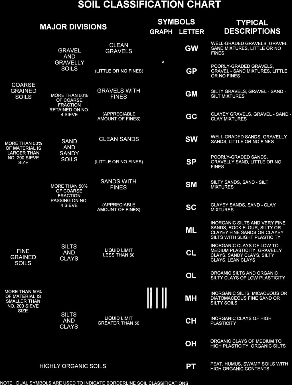

63
64 Phase 1 Boring Location Plan, Profiles, and Boring Logs

65 D B-03 B-04 B-02 B D B-01 RP-0 RP-04 PC-03 C SA-01 RP-03 RP-02 SA-02 AD-02 SA-03 C SA-04 RP-01 AD-04 FP-01 A FP-02 FP-03 PC-02 FP-04 PC-01 FP-0 FP-06 AD-01 AD-0 AD-03 A B AD-06 REFERENCE USED TO PRODUCE THIS DRAWING: Google Earth satellite image dated BORING LOCATION PLAN DATE: 01/21/1 PROJECT NO: PROJECT NAME / LOCATION: SCALE: NTS OK10004 (Phase 1) Proposed Cherokee Springs Plaza Tahlequah, Oklahoma
66 A S FP-01 (#4) N N A' FP-01 (#4) FP-02 (#3) FP-03 (#2) PC-01 (#29) FP-04 (#2) FP-0 (#24) FP-06 (#23) AD-0 (#14) AD-06 (#11) FP-02 (#3) N 810 Site Map Scale 1 inch equals 1,3 feet Explanation ELEVATION (feet) AD-06 (#11) N AD-0 (#14) 7 N FP-0 (#24) 8 N FP-06 (#23) 4 7 N FP-04 (#2) 7 6 N 10 PC-01 (#29) 6 8 N FP-03 (#2) N BT=Boring Termination AR=Auger Refusal PPqu=Unconfined compressive strength estimate from pocket penetrometer test (tsf) N=Standard Penetration Test N-Value Topsoil USCS Low to High Plasticity Clay Limestone USCS High Plasticity Clay Weathered Rock USCS Poorly-graded Sand with Clay FANWNL01 OK10004-BORING LOG.GPJ BESI.GDT 2/11/ BT= BT= BT=8.0 BT=6. 0+ BT=9.0 BT=9.0 BT=9. BT= ,000 1,200 1,400 1,600 1,800 2,000 2,200 2, BT= JOB NUMBER Water Level Reading at time of drilling East Newton Street, Suite 111 Tulsa, Oklahoma West Frontage A-A' Subsurface Profile Proposed Cherokee Springs Plaza Tahlequah, Oklahoma OK10004 Water Level Reading after drilling Horizontal Scale (feet) Vertical Exaggeration: 111x Building & Earth Sciences, Inc. PLATE NUMBER Plate A-1 DATE 2/11/1
67 B SW NE B' RP-0 (#19) RP-04 (#18) AD-03 (#13) N AD-02 (#16) N AD-03 (#13) AD-06 (#11) AD-02 (#16) Site Map Scale 1 inch equals 73 feet Explanation ELEVATION (feet) AD-06 (#11) N RP-04 (#18) 4 8 N RP-0 (#19) N BT=Boring Termination AR=Auger Refusal PPqu=Unconfined compressive strength estimate from pocket penetrometer test (tsf) N=Standard Penetration Test N-Value Topsoil USCS High Plasticity Clay 8 Limestone Weathered Rock USCS Low to High Plasticity Clay FANWNL01 OK10004-BORING LOG.GPJ BESI.GDT 2/11/ BT=8.0 BT=12.0 BT=1.0 BT= ,000 1,100 1,200 1, BT= JOB NUMBER Water Level Reading at time of drilling East Newton Street, Suite 111 Tulsa, Oklahoma Auto Dealer/Retail Pad B-B' Subsurface Profile Proposed Cherokee Springs Plaza Tahlequah, Oklahoma OK10004 Water Level Reading after drilling Horizontal Scale (feet) Vertical Exaggeration: 66.x Building & Earth Sciences, Inc. PLATE NUMBER Plate B-1 DATE 2/11/1
68 822 C S N C' 822 PC-03 (#27) SA-01 (#26) RP-04 (#18) SA-02 (#17) 820 SA-04 (#9) N 820 SA-03 (#10) SA-04 (#9) Site Map Scale 1 inch equals 1,3 feet Explanation BT=Boring Termination ELEVATION (feet) BT=7. SA-03 (#10) 4 N AR=Auger Refusal PPqu=Unconfined compressive strength estimate from pocket penetrometer test (tsf) N=Standard Penetration Test N-Value Topsoil USCS High Plasticity Clay SA-02 (#17) N SA-01 (#26) N 806 Weathered Rock USCS Low Plasticity Clay FANWNL01 OK10004-BORING LOG.GPJ BESI.GDT 2/11/ BT=. 9 9 BT=7.0 RP-04 (#18) BT=9.0 PC-03 (#27) BT= ,000 1,200 1,400 1,600 1,800 2,000 2,200 2, N BT= N Boulders and cobbles JOB NUMBER Water Level Reading at time of drilling East Newton Street, Suite 111 Tulsa, Oklahoma South Access/Retail Pad C-C' Subsurface Profile Proposed Cherokee Springs Plaza Tahlequah, Oklahoma OK10004 PLATE NUMBER Plate C-1 USCS Low Plasticity Gravelly Clay Water Level Reading after drilling Horizontal Scale (feet) Vertical Exaggeration: 74x Building & Earth Sciences, Inc. DATE 2/11/1
69 D SW NE D' B-03 (#) B-02 (#6) 21 B-04 (#8) N B-01 (#7) B-04 (#8) Site Map Scale 1 inch equals 67 feet Explanation ELEVATION (feet) B-01 (#7) N B-02 (#6) N BT=Boring Termination AR=Auger Refusal PPqu=Unconfined compressive strength estimate from pocket penetrometer test (tsf) N=Standard Penetration Test N-Value Topsoil Boulders and cobbles BT=1. 24 BT= USCS Low Plasticity Clay FANWNL01 OK10004-BORING LOG.GPJ BESI.GDT 2/11/ BT= B-03 (#) N BT= JOB NUMBER Water Level Reading at time of drilling East Newton Street, Suite 111 Tulsa, Oklahoma Proposed Borrow Area D-D' Subsurface Profile Proposed Cherokee Springs Plaza Tahlequah, Oklahoma OK10004 Water Level Reading after drilling Horizontal Scale (feet) Vertical Exaggeration: 27.x Building & Earth Sciences, Inc. PLATE NUMBER Plate D-1 DATE 2/11/1
70 LOG OF BORING Designation: AD-01 (#1) Sheet 1 of East Newton Street, Suite 111 Tulsa, Oklahoma Office: (918) Fax: (918) DEPTH (ft) Project Name: Proposed Cherokee Springs Plaza Project Number: OK10004 Drilling Method: 3 1/4" HSA Equipment Used: CME-0X Hammer Type: Automatic Boring Location: Auto Dealership Bldg (North) ELEVATION (ft) SAMPLE NO BLOWS PER INCREMENT WOH WOH-2-3 N-Value (tsf) Atterberg Limits % Moisture SOIL DESCRIPTION TOPSOIL (~36") 3.0 FAT CLAY CH): soft to firm, yellowish brown, gray with calcareous nodules, very moist, high plasticity Project Location: Tahlequah, Oklahoma Date Drilled: 1/12/1 Weather Conditions:Cloudy Surface Elevation: Drill Crew: Mohawk Drilling, Inc. Logged By: Terry Robinson GRAPHIC REMARKS WOH: Weight of Hammer Groundwater was measured at a depth of 10 inches 24 hours after completion of drilling firm, yellowish brown, orange and gray mottled, with black ferrous nodules and small weathered rock fragments /0." >> 8.0 (RESIDUAL) LIMESTONE: hard, gray 8.7 AUGER REFUSAL at a depth of 8.7 feet. Boring backfilled on 01/13/ Groundwater was encountered at a depth of about 7 feet during drilling. Hard drilling at 8 feet LOG OF BORING 2 OK10004-BORING LOG.GPJ BESI.GDT 2/13/ Split Spoon N-VALUE STANDARD PENETRATION RESISTANCE (AASHTO T-206) REC RECOVERY % MOISTURE PERCENT NATURAL MOISTURE CONTENT RQD ROCK QUALITY DESIGNATION GROUNDWATER LEVEL IN THE BOREHOLE UD UNDISTURBED UNCONFINED COMPRESSIVE STRENGTH ESTIMATE FROM POCKET PENETROMETER TEST Birmingham, AL Huntsville, AL Auburn, AL Columbus, GA Savannah, GA Raleigh, NC Tulsa, OK Springdale, AR Shreveport, LA Louisville, KY Niceville, FL
71 LOG OF BORING Designation: AD-02 (#16) Sheet 1 of East Newton Street, Suite 111 Tulsa, Oklahoma Office: (918) Fax: (918) DEPTH (ft) Project Name: Proposed Cherokee Springs Plaza Project Number: OK10004 Drilling Method: 3 1/4" HSA Equipment Used: CME-0X Hammer Type: Automatic Boring Location: Auto Dealership Bldg (North) ELEVATION (ft) SAMPLE NO. BLOWS PER INCREMENT N-Value (tsf) Atterberg Limits % Moisture SOIL DESCRIPTION TOPSOIL (~22") Project Location: Tahlequah, Oklahoma Date Drilled: 1/12/1 Weather Conditions:Cloudy Surface Elevation: Drill Crew: Mohawk Drilling, Inc. Logged By: Terry Robinson GRAPHIC REMARKS WOH: Weight of Hammer WOH FAT CLAY (CH): very soft, yellowish brown, orange and gray mottled with black ferrous nodules, and small weathered rock fragments, moist, high plasticity -firm, gray, grayish brown with trace black ferrous nodules 80. Groundwater was measured at a depth of 3 feet 24 hours after completion of drilling gray with yellowish brown and orange mottled, more abundant black ferrous nodules soft, wet with ferrous seams Groundwater was encountered at a depth of about 8 feet during drilling LIMESTONE: hard (RESIDUAL) Hard drilling at 10. feet AUGER REFUSAL at a depth of 12 feet. Boring backfilled on 01/13/ LOG OF BORING 2 OK10004-BORING LOG.GPJ BESI.GDT 2/13/ Split Spoon N-VALUE STANDARD PENETRATION RESISTANCE (AASHTO T-206) REC RECOVERY % MOISTURE PERCENT NATURAL MOISTURE CONTENT RQD ROCK QUALITY DESIGNATION GROUNDWATER LEVEL IN THE BOREHOLE UD UNDISTURBED UNCONFINED COMPRESSIVE STRENGTH ESTIMATE FROM POCKET PENETROMETER TEST Birmingham, AL Huntsville, AL Auburn, AL Columbus, GA Savannah, GA Raleigh, NC Tulsa, OK Springdale, AR Shreveport, LA Louisville, KY Niceville, FL
72 LOG OF BORING Designation: AD-03 (#13) Sheet 1 of East Newton Street, Suite 111 Tulsa, Oklahoma Office: (918) Fax: (918) DEPTH (ft) Project Name: Proposed Cherokee Springs Plaza Project Number: OK10004 Drilling Method: 3 1/4" HSA Equipment Used: CME-0X Hammer Type: Automatic Boring Location: Auto Dealership Bldg (south) ELEVATION (ft) SAMPLE NO BLOWS PER INCREMENT N-Value (tsf) Atterberg Limits % Moisture SOIL DESCRIPTION TOPSOIL (~36") 3.0 FAT CLAY (CH): stiff, yellowish brown, orange, and gray mottled, with weathered sandstone fragments, moist, high plasticity Project Location: Tahlequah, Oklahoma Date Drilled: 1/1/1 Weather Conditions:Clear Surface Elevation: Drill Crew: Mohawk Drilling, Inc. Logged By: Terry Robinson GRAPHIC REMARKS Note: Standing water observed at ground surface. Groundwater was encountered at a depth of about 1 foot during drilling firm, gray, with orange mottled REC=92 RQD= gray, yellowish brown, with fine sand (RESIDUAL) HIGHLY WEATHERED SHALE: soft, brown, gray brown, with hard limestone fragments 11.0 LIMESTONE: hard, gray, with white calcite seams and few vugs, medium bedded with closed bedding joints - dark gray, shaly from 11. to 13.0 feet light gray, with calcite seams below 13.0 feet Groundwater was measured at 7. feet prior to rock coring. Begin with NQ rock coring tools at 11 feet. Run #1: 11.0 to 1.0 feet LOG OF BORING 2 OK10004-BORING LOG.GPJ BESI.GDT 2/13/ Split Spoon Rock Core 1.0 Boring terminated at a depth of 1 feet. Boring backfilled on 01/16/201. N-VALUE STANDARD PENETRATION RESISTANCE (AASHTO T-206) REC RECOVERY % MOISTURE PERCENT NATURAL MOISTURE CONTENT RQD ROCK QUALITY DESIGNATION GROUNDWATER LEVEL IN THE BOREHOLE UD UNDISTURBED UNCONFINED COMPRESSIVE STRENGTH ESTIMATE FROM POCKET PENETROMETER TEST Birmingham, AL Huntsville, AL Auburn, AL Columbus, GA Savannah, GA Raleigh, NC Tulsa, OK Springdale, AR Shreveport, LA Louisville, KY Niceville, FL
73 LOG OF BORING Designation: AD-04 (#12) Sheet 1 of East Newton Street, Suite 111 Tulsa, Oklahoma Office: (918) Fax: (918) DEPTH (ft) Project Name: Proposed Cherokee Springs Plaza Project Number: OK10004 Drilling Method: 3 1/4" HSA Equipment Used: CME-0X Hammer Type: Automatic Boring Location: Auto Dealership Bldg (South) ELEVATION (ft) SAMPLE NO. BLOWS PER INCREMENT N-Value (tsf) Atterberg Limits % Moisture SOIL DESCRIPTION TOPSOIL (~22") Project Location: Tahlequah, Oklahoma Date Drilled: 1/12/1 Weather Conditions:Cloudy Surface Elevation: Drill Crew: Mohawk Drilling, Inc. Logged By: Terry Robinson GRAPHIC REMARKS /0." >> 1.8 LEAN TO FAT CLAY (CL-CH): soft, brown, yellowish brown, very moist, moderate to high plasticity -firm, brown, yellowish brown with tan silty pockets, moist 4. (RESIDUAL).0 LIMESTONE: hard, gray, sandy AUGER REFUSAL at a depth of feet. Boring backfilled on 01/13/ hard drilling Groundwater was not encountered during drilling and boring dry prior to backfilling LOG OF BORING 2 OK10004-BORING LOG.GPJ BESI.GDT 2/13/ Split Spoon N-VALUE STANDARD PENETRATION RESISTANCE (AASHTO T-206) REC RECOVERY % MOISTURE PERCENT NATURAL MOISTURE CONTENT RQD ROCK QUALITY DESIGNATION GROUNDWATER LEVEL IN THE BOREHOLE UD UNDISTURBED UNCONFINED COMPRESSIVE STRENGTH ESTIMATE FROM POCKET PENETROMETER TEST Birmingham, AL Huntsville, AL Auburn, AL Columbus, GA Savannah, GA Raleigh, NC Tulsa, OK Springdale, AR Shreveport, LA Louisville, KY Niceville, FL
74 LOG OF BORING Designation: AD-0 (#14) Sheet 1 of East Newton Street, Suite 111 Tulsa, Oklahoma Office: (918) Fax: (918) DEPTH (ft) Project Name: Proposed Cherokee Springs Plaza Project Number: OK10004 Drilling Method: 3 1/4" HSA Equipment Used: CME-0X Hammer Type: Automatic Boring Location: Car Dealership Site ELEVATION (ft) SAMPLE NO BLOWS PER INCREMENT N-Value (tsf) Atterberg Limits % Moisture SOIL DESCRIPTION 0.2 TOPSOIL (~2") FAT CLAY (CH): firm, gray, gray brown, dark gray, with fine roots and trace small sandstone fragments, very moist, high 2. plasticity FAT CLAY (CH): firm, yellowish brown and gray mottled, with black ferrous nodules, moist, high plasticity Project Location: Tahlequah, Oklahoma Date Drilled: 1/12/1 Weather Conditions:Cloudy Surface Elevation: Drill Crew: Mohawk Drilling, Inc. Logged By: Terry Robinson GRAPHIC REMARKS Groundwater was measured at 1. feet 24 hours after completion of drilling LEAN TO FAT CLAY (CL-CH): stiff, gray, yellowish brown and orange mottled, with 6. trace calcareous nodules and fine sand, moist, moderate to high plasticity (RESIDUAL) HIGHLY WEATHERED SHALE: soft, yellowish brown, brown /6" >> - soft layer LIMESTONE: hard, light gray Boring terminated at a depth of 10 feet. Boring backfilled on 01/13/ Boring was dry prior to backfilling. 1 LOG OF BORING 2 OK10004-BORING LOG.GPJ BESI.GDT 2/13/ Split Spoon N-VALUE STANDARD PENETRATION RESISTANCE (AASHTO T-206) REC RECOVERY % MOISTURE PERCENT NATURAL MOISTURE CONTENT RQD ROCK QUALITY DESIGNATION GROUNDWATER LEVEL IN THE BOREHOLE UD UNDISTURBED UNCONFINED COMPRESSIVE STRENGTH ESTIMATE FROM POCKET PENETROMETER TEST Birmingham, AL Huntsville, AL Auburn, AL Columbus, GA Savannah, GA Raleigh, NC Tulsa, OK Springdale, AR Shreveport, LA Louisville, KY Niceville, FL
75 LOG OF BORING Designation: AD-06 (#11) Sheet 1 of East Newton Street, Suite 111 Tulsa, Oklahoma Office: (918) Fax: (918) DEPTH (ft) Project Name: Proposed Cherokee Springs Plaza Project Number: OK10004 Drilling Method: 3 1/4" HSA Equipment Used: CME-0X Hammer Type: Automatic Boring Location: Car Dealership Site ELEVATION (ft) SAMPLE NO. BLOWS PER INCREMENT N-Value (tsf) Atterberg Limits % Moisture SOIL DESCRIPTION TOPSOIL (~24") Project Location: Tahlequah, Oklahoma Date Drilled: 1/12/1 Weather Conditions:Cloudy Surface Elevation: Drill Crew: Mohawk Drilling, Inc. Logged By: Terry Robinson GRAPHIC REMARKS WOH: Weight of Hammer WOH FAT CLAY (CH): firm, gray, yellowish brown and orange mottled, very moist, high plasticity /." >> LEAN TO FAT CLAY (CL-CH): stiff, gray, yellowish brown, with orange brown weathered sandstone fragments and fine sand, blocky, moist, moderate to high plasticity (RESIDUAL) LIMESTONE: hard, gray AUGER REFUSAL at a depth of 8 feet. Boring backfilled on 01/13/ hard drilling Groundwater was not encountered during drilling and boring dry upon completion of drilling. Boring was dry prior to backfilling LOG OF BORING 2 OK10004-BORING LOG.GPJ BESI.GDT 2/13/ Split Spoon N-VALUE STANDARD PENETRATION RESISTANCE (AASHTO T-206) REC RECOVERY % MOISTURE PERCENT NATURAL MOISTURE CONTENT RQD ROCK QUALITY DESIGNATION GROUNDWATER LEVEL IN THE BOREHOLE UD UNDISTURBED UNCONFINED COMPRESSIVE STRENGTH ESTIMATE FROM POCKET PENETROMETER TEST Birmingham, AL Huntsville, AL Auburn, AL Columbus, GA Savannah, GA Raleigh, NC Tulsa, OK Springdale, AR Shreveport, LA Louisville, KY Niceville, FL
76 LOG OF BORING Designation: B-01 (#7) Sheet 1 of East Newton Street, Suite 111 Tulsa, Oklahoma Office: (918) Fax: (918) DEPTH (ft) Project Name: Proposed Cherokee Springs Plaza Project Number: OK10004 Drilling Method: 3 1/4" HSA Equipment Used: CME-0X Hammer Type: Automatic Boring Location: Borrow Area ELEVATION (ft) SAMPLE NO. 1 BLOWS PER INCREMENT N-Value (tsf) Atterberg Limits % Moisture SOIL DESCRIPTION 0.6 TOPSOIL (~6") BRECCIATED CHERT: dense, white, gray, red and brown, with clayey chert, chert cobbles and trace boulders Project Location: Tahlequah, Oklahoma Date Drilled: 1/1/1 Weather Conditions:Clear Surface Elevation: Drill Crew: Mohawk Drilling, Inc. Logged By: Terry Robinson GRAPHIC REMARKS /6" >> -very dense 3 0/4." >> /2.2" >> - with orange-brown sandy lean clay seam, moist hard drilling LOG OF BORING 2 OK10004-BORING LOG.GPJ BESI.GDT 2/13/ /4" Split Spoon >> 13.9 Boring terminated at a depth of 13.9 feet. Boring backfilled on 01/16/201. N-VALUE STANDARD PENETRATION RESISTANCE (AASHTO T-206) REC RECOVERY % MOISTURE PERCENT NATURAL MOISTURE CONTENT RQD ROCK QUALITY DESIGNATION GROUNDWATER LEVEL IN THE BOREHOLE UD UNDISTURBED UNCONFINED COMPRESSIVE STRENGTH ESTIMATE FROM POCKET PENETROMETER TEST Groundwater was not encountered during drilling and boring dry upon completion of drilling. Boring was dry prior to backfilling. Birmingham, AL Huntsville, AL Auburn, AL Columbus, GA Savannah, GA Raleigh, NC Tulsa, OK Springdale, AR Shreveport, LA Louisville, KY Niceville, FL
77 LOG OF BORING Designation: B-02 (#6) Sheet 1 of East Newton Street, Suite 111 Tulsa, Oklahoma Office: (918) Fax: (918) DEPTH (ft) Project Name: Proposed Cherokee Springs Plaza Project Number: OK10004 Drilling Method: 3 1/4" HSA Equipment Used: CME-0X Hammer Type: Automatic Boring Location: Borrow Area ELEVATION (ft) SAMPLE NO BLOWS PER INCREMENT /" N-Value (tsf) Atterberg Limits % Moisture >> SOIL DESCRIPTION Project Location: Tahlequah, Oklahoma Date Drilled: 1/13/1 Weather Conditions:Clear Surface Elevation: Drill Crew: Mohawk Drilling, Inc. Logged By: Terry Robinson REMARKS 0.4 TOPSOIL (~") LEAN CLAY (CL): stiff, brown, dark brown, 1. with white and gray chert fragments, moist, hard drilling low plasticity Groundwater was not (RESIDUAL) encountered during drilling, AUGER REFUSAL ON BRECCIATED and boring was dry upon CHERT at a depth of 1. feet. completion. Boring backfilled on 01/14/201. Boring was dry prior to backfilling. GRAPHIC LOG OF BORING 2 OK10004-BORING LOG.GPJ BESI.GDT 2/13/ Split Spoon N-VALUE STANDARD PENETRATION RESISTANCE (AASHTO T-206) REC RECOVERY % MOISTURE PERCENT NATURAL MOISTURE CONTENT RQD ROCK QUALITY DESIGNATION GROUNDWATER LEVEL IN THE BOREHOLE UD UNDISTURBED UNCONFINED COMPRESSIVE STRENGTH ESTIMATE FROM POCKET PENETROMETER TEST Birmingham, AL Huntsville, AL Auburn, AL Columbus, GA Savannah, GA Raleigh, NC Tulsa, OK Springdale, AR Shreveport, LA Louisville, KY Niceville, FL
78 LOG OF BORING Designation: B-03 (#) Sheet 1 of East Newton Street, Suite 111 Tulsa, Oklahoma Office: (918) Fax: (918) DEPTH (ft) Project Name: Proposed Cherokee Springs Plaza Project Number: OK10004 Drilling Method: 3 1/4" HSA Equipment Used: CME-0X Hammer Type: Automatic Boring Location: Borrow Area ELEVATION (ft) SAMPLE NO. 820 BLOWS PER INCREMENT N-Value (tsf) Atterberg Limits % Moisture SOIL DESCRIPTION TOPSOIL (~17") Project Location: Tahlequah, Oklahoma Date Drilled: 1/13/1 Weather Conditions:Clear Surface Elevation: Drill Crew: Mohawk Drilling, Inc. Logged By: Terry Robinson GRAPHIC REMARKS /6" 0/1." >> >> LEAN CLAY (CL): soft, orange-brown, brown with white chert fragments, wet, moderate plasticity (RESIDUAL) BRECCIATED CHERT: dense, white, gray, and brown, with chert cobbles and trace 4. boulders AUGER REFUSAL ON BRECCIATED CHERT at a depth of 4. feet. Boring backfilled on 01/14/ hard drilling Groundwater was not encountered during drilling, and boring was dry upon completion. Boring was dry prior to backfilling LOG OF BORING 2 OK10004-BORING LOG.GPJ BESI.GDT 2/13/ Split Spoon N-VALUE STANDARD PENETRATION RESISTANCE (AASHTO T-206) REC RECOVERY % MOISTURE PERCENT NATURAL MOISTURE CONTENT RQD ROCK QUALITY DESIGNATION GROUNDWATER LEVEL IN THE BOREHOLE UD UNDISTURBED UNCONFINED COMPRESSIVE STRENGTH ESTIMATE FROM POCKET PENETROMETER TEST Birmingham, AL Huntsville, AL Auburn, AL Columbus, GA Savannah, GA Raleigh, NC Tulsa, OK Springdale, AR Shreveport, LA Louisville, KY Niceville, FL
79 LOG OF BORING Designation: B-04 (#8) Sheet 1 of East Newton Street, Suite 111 Tulsa, Oklahoma Office: (918) Fax: (918) DEPTH (ft) Project Name: Proposed Cherokee Springs Plaza Project Number: OK10004 Drilling Method: 3 1/4" HSA Equipment Used: CME-0X Hammer Type: Automatic Boring Location: Borrow Area ELEVATION (ft) SAMPLE NO BLOWS PER INCREMENT N-Value (tsf) Atterberg Limits % Moisture >> SOIL DESCRIPTION TOPSOIL (~8") 0.7 GRAVELLY LEAN CLAY (CL): very stiff, dark brown, reddish brown with white and 2.0 gray chert fragments, moist, low plasticity (RESIDUAL) BRECCIATED CHERT: dense, white, gray, and reddish brown, with chert cobbles and trace boulders Project Location: Tahlequah, Oklahoma Date Drilled: 1/1/1 Weather Conditions:Clear Surface Elevation: Drill Crew: Mohawk Drilling, Inc. Logged By: Terry Robinson GRAPHIC REMARKS medium dense with reddish brown gravely lean clay seams 840 moderately hard drilling 4 0/6" >> -very dense >> - with reddish brown lean clay seams 1 LOG OF BORING 2 OK10004-BORING LOG.GPJ BESI.GDT 2/13/ Split Spoon - apparent clay layer from 17 to 18. feet (softer drilling) -medium dense with reddish brown lean clay 20.0 seams Boring terminated at a depth of 20 feet. Boring backfilled on 01/16/201. N-VALUE STANDARD PENETRATION RESISTANCE (AASHTO T-206) REC RECOVERY % MOISTURE PERCENT NATURAL MOISTURE CONTENT RQD ROCK QUALITY DESIGNATION GROUNDWATER LEVEL IN THE BOREHOLE UD UNDISTURBED UNCONFINED COMPRESSIVE STRENGTH ESTIMATE FROM POCKET PENETROMETER TEST soft drilling from feet Groundwater was not encountered during drilling, and boring was dry upon completion. Boring was dry prior to backfilling. Birmingham, AL Huntsville, AL Auburn, AL Columbus, GA Savannah, GA Raleigh, NC Tulsa, OK Springdale, AR Shreveport, LA Louisville, KY Niceville, FL
80 LOG OF BORING Designation: FP-01 (#4) Sheet 1 of East Newton Street, Suite 111 Tulsa, Oklahoma Office: (918) Fax: (918) DEPTH (ft) Project Name: Proposed Cherokee Springs Plaza Project Number: OK10004 Drilling Method: 3 1/4" HSA Equipment Used: CME-0X Hammer Type: Automatic Boring Location: Frontage Retail Pad #1 ELEVATION (ft) SAMPLE NO. BLOWS PER INCREMENT N-Value (tsf) Atterberg Limits % Moisture SOIL DESCRIPTION TOPSOIL (~24") Project Location: Tahlequah, Oklahoma Date Drilled: 1/16/1 Weather Conditions:Clear Surface Elevation: Drill Crew: Mohawk Drilling, Inc. Logged By: Terry Robinson GRAPHIC REMARKS FAT CLAY (CH): stiff, yellowish brown, gray and orange mottled with black ferrous nodules and silty pockets, moist, high plasticity with fine sand pockets and calcareous nodules (RESIDUAL) HIGHLY WEATHERED SHALE: soft, brown, yellowish brown, silty 802. moderately hard drilling LOG OF BORING 2 OK10004-BORING LOG.GPJ BESI.GDT 2/13/ /3." Split Spoon >> -apparent limestone seam from 12 to 13 feet (hard drilling) -yellowish brown, orange, gray, friable LIMESTONE: hard, gray, dark gray, sandy Boring terminated at a depth of 14.3 feet. Boring backfilled on 01/17/201. Conceptual Final Grade = 814 feet; Anticipated Fill ~ 2 feet N-VALUE STANDARD PENETRATION RESISTANCE (AASHTO T-206) REC RECOVERY % MOISTURE PERCENT NATURAL MOISTURE CONTENT RQD ROCK QUALITY DESIGNATION GROUNDWATER LEVEL IN THE BOREHOLE UD UNDISTURBED UNCONFINED COMPRESSIVE STRENGTH ESTIMATE FROM POCKET PENETROMETER TEST regular drilling Groundwater was not encountered during drilling, and boring was dry upon completion. Boring was dry prior to backfilling. Birmingham, AL Huntsville, AL Auburn, AL Columbus, GA Savannah, GA Raleigh, NC Tulsa, OK Springdale, AR Shreveport, LA Louisville, KY Niceville, FL
81 LOG OF BORING Designation: FP-02 (#3) Sheet 1 of East Newton Street, Suite 111 Tulsa, Oklahoma Office: (918) Fax: (918) DEPTH (ft) Project Name: Proposed Cherokee Springs Plaza Project Number: OK10004 Drilling Method: 3 1/4" HSA Equipment Used: CME-0X Hammer Type: Automatic Boring Location: Frontage Retail Pad #2 ELEVATION (ft) SAMPLE NO BLOWS PER INCREMENT N-Value (tsf) Atterberg Limits % Moisture SOIL DESCRIPTION TOPSOIL (~30") 2. LEAN CLAY (CL): stiff, brown, very moist, 3. low plasticity FAT CLAY (CH): stiff, yellowish brown, tan, orange, moist, high plasticity - yellowish brown and gray mottled, blocky, with trace calcareous nodules and silty pockets, black ferrous staining Project Location: Tahlequah, Oklahoma Date Drilled: 1/13/1 Weather Conditions:Clear Surface Elevation: Drill Crew: Mohawk Drilling, Inc. Logged By: Terry Robinson GRAPHIC REMARKS Sample #1: feet Atterberg Limits: LL=26, PL=22, PI= POORLY GRADED SAND WITH CLAY (SP-SC): medium dense, yellowish brown, 9. gray brown, fine to medium grained, wet, with moderate plasticity clay (RESIDUAL) AUGER REFUSAL at a depth of 9. feet. Split spoon advanced to 10 feet. Boring backfilled on 01/14/201. Conceptual Final Grade = 809 feet; Anticipated Cut ~ 1 foot Groundwater was encountered at a depth of about 9. feet during drilling. Boring dry upon completion of drilling. Boring was dry prior to backfilling. LOG OF BORING 2 OK10004-BORING LOG.GPJ BESI.GDT 2/13/ Split Spoon N-VALUE STANDARD PENETRATION RESISTANCE (AASHTO T-206) REC RECOVERY % MOISTURE PERCENT NATURAL MOISTURE CONTENT RQD ROCK QUALITY DESIGNATION GROUNDWATER LEVEL IN THE BOREHOLE UD UNDISTURBED UNCONFINED COMPRESSIVE STRENGTH ESTIMATE FROM POCKET PENETROMETER TEST Birmingham, AL Huntsville, AL Auburn, AL Columbus, GA Savannah, GA Raleigh, NC Tulsa, OK Springdale, AR Shreveport, LA Louisville, KY Niceville, FL
82 LOG OF BORING Designation: FP-03 (#2) Sheet 1 of East Newton Street, Suite 111 Tulsa, Oklahoma Office: (918) Fax: (918) DEPTH (ft) Project Name: Proposed Cherokee Springs Plaza Project Number: OK10004 Drilling Method: 3 1/4" HSA Equipment Used: CME-0X Hammer Type: Automatic Boring Location: Frontage Retail Pad #3 ELEVATION (ft) SAMPLE NO BLOWS PER INCREMENT N-Value (tsf) Atterberg Limits % Moisture SOIL DESCRIPTION 0.3 TOPSOIL (~3.") 1.0 LEAN TO FAT CLAY (CL-CH): firm, gray brown, yellowish brown with fine roots, very moist, moderate to high plasticity FAT CLAY (CH): firm, gray brown, olive brown, very moist, high plasticity - moist at 2. feet Project Location: Tahlequah, Oklahoma Date Drilled: 1/13/1 Weather Conditions:Clear Surface Elevation: Drill Crew: Mohawk Drilling, Inc. Logged By: Terry Robinson GRAPHIC REMARKS FAT CLAY (CH): stiff, gray, yellowish brown, with orange-brown mottled, with small calcareous nodules, moist, high plasticity Sample #3:.0-6. feet Atterberg Limits: LL=2, PL=19, PI= yellowish brown, gray, with orange mottled, with black ferrous nodules and sandy pockets (RESIDUAL) AUGER REFUSAL at a depth of 10. feet. Boring backfilled on 01/14/201. Conceptual Final Grade = 810 feet; Anticipated Fill ~ 2 feet 797. Groundwater was not encountered during drilling and boring dry upon completion of drilling. Boring was dry prior to backfilling. 1 LOG OF BORING 2 OK10004-BORING LOG.GPJ BESI.GDT 2/13/ Split Spoon N-VALUE STANDARD PENETRATION RESISTANCE (AASHTO T-206) REC RECOVERY % MOISTURE PERCENT NATURAL MOISTURE CONTENT RQD ROCK QUALITY DESIGNATION GROUNDWATER LEVEL IN THE BOREHOLE UD UNDISTURBED UNCONFINED COMPRESSIVE STRENGTH ESTIMATE FROM POCKET PENETROMETER TEST Birmingham, AL Huntsville, AL Auburn, AL Columbus, GA Savannah, GA Raleigh, NC Tulsa, OK Springdale, AR Shreveport, LA Louisville, KY Niceville, FL
83 LOG OF BORING Designation: FP-04 (#2) Sheet 1 of East Newton Street, Suite 111 Tulsa, Oklahoma Office: (918) Fax: (918) DEPTH (ft) Project Name: Proposed Cherokee Springs Plaza Project Number: OK10004 Drilling Method: 3 1/4" HSA Equipment Used: CME-0X Hammer Type: Automatic Boring Location: Frontage Retail Pad #4 ELEVATION (ft) SAMPLE NO BLOWS PER INCREMENT N-Value (tsf) Atterberg Limits % Moisture SOIL DESCRIPTION 0.2 TOPSOIL (~2") FAT CLAY (CH): firm, dark gray, gray brown, with fine roots and small white 2.0 calcareous nodules, moist, high plasticity FAT CLAY (CH): firm, yellowish brown, orange, and gray mottled, with black ferrous nodules, moist, high plasticity Project Location: Tahlequah, Oklahoma Date Drilled: 1/13/1 Weather Conditions:Clear Surface Elevation: Drill Crew: Mohawk Drilling, Inc. Logged By: Terry Robinson GRAPHIC REMARKS Sample #1: feet Atterberg Limits: LL=9, PL=22, PI=37 Groundwater was measured at 3 feet 24 hours after completion of drilling stiff, blocky, with weathered sandstone fragments and calcareous nodules /0." >> 8. (RESIDUAL) 9.0 LIMESTONE: hard, gray, sandy AUGER REFUSAL at a depth of 9 feet. Boring backfilled on 01/14/ Groundwater was encountered at a depth of about 8. feet during drilling. Conceptual Final Grade = 810 feet; Anticipated Fill ~ 2 feet 79 1 LOG OF BORING 2 OK10004-BORING LOG.GPJ BESI.GDT 2/13/ Split Spoon N-VALUE STANDARD PENETRATION RESISTANCE (AASHTO T-206) REC RECOVERY % MOISTURE PERCENT NATURAL MOISTURE CONTENT RQD ROCK QUALITY DESIGNATION GROUNDWATER LEVEL IN THE BOREHOLE UD UNDISTURBED UNCONFINED COMPRESSIVE STRENGTH ESTIMATE FROM POCKET PENETROMETER TEST Birmingham, AL Huntsville, AL Auburn, AL Columbus, GA Savannah, GA Raleigh, NC Tulsa, OK Springdale, AR Shreveport, LA Louisville, KY Niceville, FL
84 LOG OF BORING Designation: FP-0 (#24) Sheet 1 of East Newton Street, Suite 111 Tulsa, Oklahoma Office: (918) Fax: (918) DEPTH (ft) Project Name: Proposed Cherokee Springs Plaza Project Number: OK10004 Drilling Method: 3 1/4" HSA Equipment Used: CME-0X Hammer Type: Automatic Boring Location: Frontage Retail Pad # ELEVATION (ft) SAMPLE NO BLOWS PER INCREMENT WOH N-Value (tsf) Atterberg Limits % Moisture SOIL DESCRIPTION 0.3 TOPSOIL (~4") FAT CLAY (CH): very soft, gray brown, with orange mottled, with small calcareous nodules and fine roots, moist, high plasticity - firm to stiff, gray, dark gray, with orange mottled, with silty pockets Project Location: Tahlequah, Oklahoma Date Drilled: 1/13/1 Weather Conditions:Clear Surface Elevation: Drill Crew: Mohawk Drilling, Inc. Logged By: Terry Robinson 806. GRAPHIC REMARKS WOH: Weight of Hammer /2" >> - stiff, orange with gray mottled, with. weathered rock fragments, black ferrous nodules, and medium sand (RESIDUAL) 6. LIMESTONE: moderately hard, gray, sandy AUGER REFUSAL at a depth of 6. feet. Boring backfilled on 01/14/ hard drilling Groundwater was not encountered during drilling and boring dry upon completion of drilling. Boring was dry prior to backfilling LOG OF BORING 2 OK10004-BORING LOG.GPJ BESI.GDT 2/13/ Split Spoon N-VALUE STANDARD PENETRATION RESISTANCE (AASHTO T-206) REC RECOVERY % MOISTURE PERCENT NATURAL MOISTURE CONTENT RQD ROCK QUALITY DESIGNATION GROUNDWATER LEVEL IN THE BOREHOLE UD UNDISTURBED UNCONFINED COMPRESSIVE STRENGTH ESTIMATE FROM POCKET PENETROMETER TEST Birmingham, AL Huntsville, AL Auburn, AL Columbus, GA Savannah, GA Raleigh, NC Tulsa, OK Springdale, AR Shreveport, LA Louisville, KY Niceville, FL
85 LOG OF BORING Designation: FP-06 (#23) Sheet 1 of East Newton Street, Suite 111 Tulsa, Oklahoma Office: (918) Fax: (918) DEPTH (ft) Project Name: Proposed Cherokee Springs Plaza Project Number: OK10004 Drilling Method: 3 1/4" HSA Equipment Used: CME-0X Hammer Type: Automatic Boring Location: Frontage Retail Pad #6 ELEVATION (ft) SAMPLE NO BLOWS PER INCREMENT N-Value (tsf) Atterberg Limits % Moisture SOIL DESCRIPTION 0.3 TOPSOIL (~4") FAT CLAY (CH): soft, gray brown, gray, with fine roots and small calcareous nodules, moist, high plasticity 2. FAT CLAY (CH): firm, yellowish brown, orange, with gray mottled, with reddish brown to black ferrous staining, moist, high plasticity Project Location: Tahlequah, Oklahoma Date Drilled: 1/13/1 Weather Conditions:Clear Surface Elevation: Drill Crew: Mohawk Drilling, Inc. Logged By: Terry Robinson GRAPHIC REMARKS stiff, with black ferrous nodules /0." >> 7. (RESIDUAL) LIMESTONE: hard, gray, sandy hard drilling AUGER REFUSAL at a depth of 8 feet. Groundwater was Boring backfilled on 01/14/201. encountered at a depth of about 7. feet during drilling. Groundwater was measured at 8 feet upon completion of drilling. Boring was dry prior to backfilling. 1 LOG OF BORING 2 OK10004-BORING LOG.GPJ BESI.GDT 2/13/ Split Spoon N-VALUE STANDARD PENETRATION RESISTANCE (AASHTO T-206) REC RECOVERY % MOISTURE PERCENT NATURAL MOISTURE CONTENT RQD ROCK QUALITY DESIGNATION GROUNDWATER LEVEL IN THE BOREHOLE UD UNDISTURBED UNCONFINED COMPRESSIVE STRENGTH ESTIMATE FROM POCKET PENETROMETER TEST Birmingham, AL Huntsville, AL Auburn, AL Columbus, GA Savannah, GA Raleigh, NC Tulsa, OK Springdale, AR Shreveport, LA Louisville, KY Niceville, FL
86 LOG OF BORING Designation: PC-01 (#29) Sheet 1 of East Newton Street, Suite 111 Tulsa, Oklahoma Office: (918) Fax: (918) DEPTH (ft) Project Name: Proposed Cherokee Springs Plaza Project Number: OK10004 Drilling Method: 3 1/4" HSA Equipment Used: CME-0X Hammer Type: Automatic Boring Location: Primary Corridor Rwy ELEVATION (ft) SAMPLE NO BLOWS PER INCREMENT N-Value (tsf) Atterberg Limits % Moisture SOIL DESCRIPTION 0.2 TOPSOIL (~2") LEAN TO FAT CLAY (CL-CH): firm, dark 1. brown, grayish brown with fine roots and rock fragments, very moist, moderate to high plasticity FAT CLAY (CH): soft, yellowish brown, gray, moist high plasticity -firm, gray, orange-brown with black ferrous nodules Project Location: Tahlequah, Oklahoma Date Drilled: 1/13/1 Weather Conditions:Clear Surface Elevation: Drill Crew: Mohawk Drilling, Inc. Logged By: Terry Robinson GRAPHIC REMARKS FAT CLAY (CH): stiff, yellowish brown, orange and gray mottled with black ferrous nodules, moist, high plasticity Groundwater was not encountered during drilling and was measured at feet 24 hours after completion of drilling /2." >> 8.0 (RESIDUAL) WEATHERED SHALE: moderately hard, 9.0 yellowish brown, brown AUGER REFUSAL at a depth of 9 feet. Boring backfilled on 01/14/ LOG OF BORING 2 OK10004-BORING LOG.GPJ BESI.GDT 2/13/ Split Spoon N-VALUE STANDARD PENETRATION RESISTANCE (AASHTO T-206) REC RECOVERY % MOISTURE PERCENT NATURAL MOISTURE CONTENT RQD ROCK QUALITY DESIGNATION GROUNDWATER LEVEL IN THE BOREHOLE UD UNDISTURBED UNCONFINED COMPRESSIVE STRENGTH ESTIMATE FROM POCKET PENETROMETER TEST Birmingham, AL Huntsville, AL Auburn, AL Columbus, GA Savannah, GA Raleigh, NC Tulsa, OK Springdale, AR Shreveport, LA Louisville, KY Niceville, FL
87 LOG OF BORING Designation: PC-02 (#28) Sheet 1 of East Newton Street, Suite 111 Tulsa, Oklahoma Office: (918) Fax: (918) DEPTH (ft) Project Name: Proposed Cherokee Springs Plaza Project Number: OK10004 Drilling Method: 3 1/4" HSA Equipment Used: CME-0X Hammer Type: Automatic Boring Location: Primary Corridor Rwy ELEVATION (ft) SAMPLE NO. BLOWS PER INCREMENT N-Value (tsf) Atterberg Limits % Moisture SOIL DESCRIPTION TOPSOIL (~23") Project Location: Tahlequah, Oklahoma Date Drilled: 1/13/1 Weather Conditions:Clear Surface Elevation: Drill Crew: Mohawk Drilling, Inc. Logged By: Terry Robinson GRAPHIC REMARKS LEAN TO FAT CLAY (CL-CH): firm, orange-brown, gray with black ferrous nodules, moist, moderate to high plasticity -stiff /4" >>.0 FAT CLAY (CH): stiff, yellowish brown, gray with black ferrous nodules and fine sand, 6.3 moist, high plasticity 6. (RESIDUAL) LIMESTONE: hard, dark gray, sandy AUGER REFUSAL at a depth of 6. feet. Boring backfilled on 01/14/201. Conceptual Final Grade = 809 feet; Anticipated Fill ~ 2 feet Groundwater was not encountered during drilling and boring dry upon completion of drilling. Boring was dry prior to backfilling LOG OF BORING 2 OK10004-BORING LOG.GPJ BESI.GDT 2/13/ Split Spoon N-VALUE STANDARD PENETRATION RESISTANCE (AASHTO T-206) REC RECOVERY % MOISTURE PERCENT NATURAL MOISTURE CONTENT RQD ROCK QUALITY DESIGNATION GROUNDWATER LEVEL IN THE BOREHOLE UD UNDISTURBED UNCONFINED COMPRESSIVE STRENGTH ESTIMATE FROM POCKET PENETROMETER TEST Birmingham, AL Huntsville, AL Auburn, AL Columbus, GA Savannah, GA Raleigh, NC Tulsa, OK Springdale, AR Shreveport, LA Louisville, KY Niceville, FL
88 LOG OF BORING Designation: PC-03 (#27) Sheet 1 of East Newton Street, Suite 111 Tulsa, Oklahoma Office: (918) Fax: (918) DEPTH (ft) Project Name: Proposed Cherokee Springs Plaza Project Number: OK10004 Drilling Method: 3 1/4" HSA Equipment Used: CME-0X Hammer Type: Automatic Boring Location: Primary Corridor Rwy ELEVATION (ft) SAMPLE NO. 1 BLOWS PER INCREMENT N-Value (tsf) Atterberg Limits % Moisture SOIL DESCRIPTION 0.4 TOPSOIL (~") FAT CLAY (CH): soft, gray brown, gray, very moist, high plasticity Project Location: Tahlequah, Oklahoma Date Drilled: 1/14/1 Weather Conditions:Partly Cloudy Surface Elevation: Drill Crew: Mohawk Drilling, Inc. Logged By: Terry Robinson GRAPHIC REMARKS FAT CLAY (CH): stiff, gray, dark gray, with small orange weathered sandstone fragments, moist, high plasticity gray, with orange-brown mottled, with more abundant weathered sandstone fragments and black ferrous staining (RESIDUAL) AUGER REFUSAL at a depth of 7. feet. Boring backfilled on 01/16/201. Conceptual Final Grade = 803 feet; Anticipated Fill < 1 foot 79.0 Groundwater was not encountered during drilling and boring dry upon completion of drilling. Boring was dry prior to backfilling LOG OF BORING 2 OK10004-BORING LOG.GPJ BESI.GDT 2/13/ Split Spoon N-VALUE STANDARD PENETRATION RESISTANCE (AASHTO T-206) REC RECOVERY % MOISTURE PERCENT NATURAL MOISTURE CONTENT RQD ROCK QUALITY DESIGNATION GROUNDWATER LEVEL IN THE BOREHOLE UD UNDISTURBED UNCONFINED COMPRESSIVE STRENGTH ESTIMATE FROM POCKET PENETROMETER TEST Birmingham, AL Huntsville, AL Auburn, AL Columbus, GA Savannah, GA Raleigh, NC Tulsa, OK Springdale, AR Shreveport, LA Louisville, KY Niceville, FL
89 LOG OF BORING Designation: RP-01 (#22) Sheet 1 of East Newton Street, Suite 111 Tulsa, Oklahoma Office: (918) Fax: (918) DEPTH (ft) Project Name: Proposed Cherokee Springs Plaza Project Number: OK10004 Drilling Method: 3 1/4" HSA Equipment Used: CME-0X Hammer Type: Automatic Boring Location: Retail Pad #6 ELEVATION (ft) SAMPLE NO BLOWS PER INCREMENT WOH N-Value (tsf) Atterberg Limits % Moisture SOIL DESCRIPTION TOPSOIL (~18") 1. FAT CLAY (CH): firm, yellowish brown, gray, with orange mottled, with black ferrous nodules, moist, high plasticity Project Location: Tahlequah, Oklahoma Date Drilled: 1/13/1 Weather Conditions:Clear Surface Elevation: Drill Crew: Mohawk Drilling, Inc. Logged By: Terry Robinson GRAPHIC REMARKS WOH: Weight of Hammer Sample #1: feet Atterberg Limits: LL=36, PL=18, PI= gray and orange mottled, with trace calcareous nodules (RESIDUAL) HIGHLY WEATHERED SHALE: soft, gray, orange, with poorly cemented sandstone partings, friable 11. AUGER REFUSAL at a depth of 11. feet. Boring backfilled on 01/14/201. Conceptual Final Grade = 809 feet; Anticipated Fill ~ 3 feet hard drilling Groundwater was not encountered during drilling and boring dry upon completion of drilling. Boring was dry prior to backfilling. 1 LOG OF BORING 2 OK10004-BORING LOG.GPJ BESI.GDT 2/13/ Split Spoon N-VALUE STANDARD PENETRATION RESISTANCE (AASHTO T-206) REC RECOVERY % MOISTURE PERCENT NATURAL MOISTURE CONTENT RQD ROCK QUALITY DESIGNATION GROUNDWATER LEVEL IN THE BOREHOLE UD UNDISTURBED UNCONFINED COMPRESSIVE STRENGTH ESTIMATE FROM POCKET PENETROMETER TEST Birmingham, AL Huntsville, AL Auburn, AL Columbus, GA Savannah, GA Raleigh, NC Tulsa, OK Springdale, AR Shreveport, LA Louisville, KY Niceville, FL
90 LOG OF BORING Designation: RP-02 (#21) Sheet 1 of East Newton Street, Suite 111 Tulsa, Oklahoma Office: (918) Fax: (918) DEPTH (ft) Project Name: Proposed Cherokee Springs Plaza Project Number: OK10004 Drilling Method: 3 1/4" HSA Equipment Used: CME-0X Hammer Type: Automatic Boring Location: Retail Pad #6 and #7 ELEVATION (ft) SAMPLE NO BLOWS PER INCREMENT N-Value (tsf) Atterberg Limits % Moisture SOIL DESCRIPTION TOPSOIL (~30") Project Location: Tahlequah, Oklahoma Date Drilled: 1/13/1 Weather Conditions:Clear Surface Elevation: Drill Crew: Mohawk Drilling, Inc. Logged By: Terry Robinson GRAPHIC REMARKS LEAN CLAY (CL): firm, gray brown, gray, 3. with fine roots, moist, low to moderate plasticity LEAN TO FAT CLAY (CL-CH): stiff, gray, yellowish brown, orange, laminated, moist, moderate to high plasticity - gray, with orange mottled, with weathered rock fragments and silty pockets (RESIDUAL) AUGER REFUSAL at a depth of 7 feet. Boring backfilled on 01/14/201. Conceptual Final Grade = 808 feet; Anticipated Fill ~ 3 feet hard drilling Groundwater was not encountered during drilling and boring dry upon completion of drilling. Boring was dry prior to backfilling. LOG OF BORING 2 OK10004-BORING LOG.GPJ BESI.GDT 2/13/ Split Spoon N-VALUE STANDARD PENETRATION RESISTANCE (AASHTO T-206) REC RECOVERY % MOISTURE PERCENT NATURAL MOISTURE CONTENT RQD ROCK QUALITY DESIGNATION GROUNDWATER LEVEL IN THE BOREHOLE UD UNDISTURBED UNCONFINED COMPRESSIVE STRENGTH ESTIMATE FROM POCKET PENETROMETER TEST Birmingham, AL Huntsville, AL Auburn, AL Columbus, GA Savannah, GA Raleigh, NC Tulsa, OK Springdale, AR Shreveport, LA Louisville, KY Niceville, FL
91 LOG OF BORING Designation: RP-03 (#20) Sheet 1 of East Newton Street, Suite 111 Tulsa, Oklahoma Office: (918) Fax: (918) DEPTH (ft) 10 Project Name: Proposed Cherokee Springs Plaza Project Number: OK10004 Drilling Method: 3 1/4" HSA Equipment Used: CME-0X Hammer Type: Automatic Boring Location: Retail Pad #7 ELEVATION (ft) SAMPLE NO BLOWS PER INCREMENT /4" N-Value (tsf) Atterberg Limits % Moisture >> SOIL DESCRIPTION 0.6 TOPSOIL (~8") FAT CLAY (CH): stiff, gray brown, yellowish brown, with fine roots and trace 2.0 calcareous nodules, moist, high plasticity FAT CLAY (CH): firm, yellowish brown, orange, with gray mottled, with black ferrous nodules and white calcareous nodules, moist, high plasticity.6 - firm, with fine to medium sand 6.0 (RESIDUAL) LIMESTONE: moderately hard, gray, sandy AUGER REFUSAL at a depth of 6 feet. Boring backfilled on 01/16/201. Conceptual Final Grade = 807 feet; Anticipated Fill ~ 3 feet Project Location: Tahlequah, Oklahoma Date Drilled: 1/14/1 Weather Conditions:Partly Cloudy Surface Elevation: Drill Crew: Mohawk Drilling, Inc. Logged By: Terry Robinson GRAPHIC REMARKS Groundwater was not encountered during drilling and boring dry upon completion of drilling. Boring was dry prior to backfilling LOG OF BORING 2 OK10004-BORING LOG.GPJ BESI.GDT 2/13/ Split Spoon N-VALUE STANDARD PENETRATION RESISTANCE (AASHTO T-206) REC RECOVERY % MOISTURE PERCENT NATURAL MOISTURE CONTENT RQD ROCK QUALITY DESIGNATION GROUNDWATER LEVEL IN THE BOREHOLE UD UNDISTURBED UNCONFINED COMPRESSIVE STRENGTH ESTIMATE FROM POCKET PENETROMETER TEST Birmingham, AL Huntsville, AL Auburn, AL Columbus, GA Savannah, GA Raleigh, NC Tulsa, OK Springdale, AR Shreveport, LA Louisville, KY Niceville, FL
92 LOG OF BORING Designation: RP-04 (#18) Sheet 1 of East Newton Street, Suite 111 Tulsa, Oklahoma Office: (918) Fax: (918) DEPTH (ft) Project Name: Proposed Cherokee Springs Plaza Project Number: OK10004 Drilling Method: 3 1/4" HSA Equipment Used: CME-0X Hammer Type: Automatic Boring Location: Retail Pad #8 ELEVATION (ft) SAMPLE NO. BLOWS PER INCREMENT N-Value (tsf) Atterberg Limits % Moisture SOIL DESCRIPTION TOPSOIL (~30") Project Location: Tahlequah, Oklahoma Date Drilled: 1/13/1 Weather Conditions:Clear Surface Elevation: Drill Crew: Mohawk Drilling, Inc. Logged By: Terry Robinson GRAPHIC REMARKS FAT CLAY (CH): stiff, yellowish brown, orange, with gray mottled, with black ferrous nodules, moist, high plasticity firm, with calcareous nodules moderately hard drilling /2." >> 8.0 (RESIDUAL) HIGHLY WEATHERED SHALE: soft, gray, 9.0 yellowish brown, with hard gray limestone fragments and lenses AUGER REFUSAL at a depth of 9 feet. Boring backfilled on 01/14/201. Conceptual Final Grade = 809 feet; Anticipated Fill ~ 6 feet hard drilling Groundwater was encountered at a depth of about 8 feet during drilling and measured at 8 feet upon completion of drilling. Boring was dry prior to backfilling LOG OF BORING 2 OK10004-BORING LOG.GPJ BESI.GDT 2/13/ Split Spoon N-VALUE STANDARD PENETRATION RESISTANCE (AASHTO T-206) REC RECOVERY % MOISTURE PERCENT NATURAL MOISTURE CONTENT RQD ROCK QUALITY DESIGNATION GROUNDWATER LEVEL IN THE BOREHOLE UD UNDISTURBED UNCONFINED COMPRESSIVE STRENGTH ESTIMATE FROM POCKET PENETROMETER TEST Birmingham, AL Huntsville, AL Auburn, AL Columbus, GA Savannah, GA Raleigh, NC Tulsa, OK Springdale, AR Shreveport, LA Louisville, KY Niceville, FL
93 LOG OF BORING Designation: RP-0 (#19) Sheet 1 of East Newton Street, Suite 111 Tulsa, Oklahoma Office: (918) Fax: (918) DEPTH (ft) Project Name: Proposed Cherokee Springs Plaza Project Number: OK10004 Drilling Method: 3 1/4" HSA Equipment Used: CME-0X Hammer Type: Automatic Boring Location: Retail Pad #8 ELEVATION (ft) SAMPLE NO BLOWS PER INCREMENT N-Value (tsf) Atterberg Limits % Moisture SOIL DESCRIPTION 0.6 TOPSOIL (~8.") LEAN TO FAT CLAY (CL-CH): firm, gray brown, dark gray, with fine roots, moist, 2.0 moderate to high plasticity LEAN TO FAT CLAY (CL-CH): firm, gray, yellowish brown, moist, high plasticity - stiff, yellowish brown, orange, and gray mottled, with weathered sandstone fragments, black ferrous nodules, and small calcareous nodules Project Location: Tahlequah, Oklahoma Date Drilled: 1/14/1 Weather Conditions:Partly Cloudy Surface Elevation: Drill Crew: Mohawk Drilling, Inc. Logged By: Terry Robinson GRAPHIC REMARKS Sample #2: feet Atterberg Limits: LL=4, PL=19, PI= /3" >> 9.0 (RESIDUAL) 9. LIMESTONE: hard, gray, dark gray, sandy AUGER REFUSAL at a depth of 9. feet. Boring backfilled on 01/16/201. Conceptual Final Grade = 808 feet; Anticipated Fill ~ 6 feet Groundwater was not encountered during drilling and boring dry upon completion of drilling. Boring was dry prior to backfilling. 1 LOG OF BORING 2 OK10004-BORING LOG.GPJ BESI.GDT 2/13/ Split Spoon N-VALUE STANDARD PENETRATION RESISTANCE (AASHTO T-206) REC RECOVERY % MOISTURE PERCENT NATURAL MOISTURE CONTENT RQD ROCK QUALITY DESIGNATION GROUNDWATER LEVEL IN THE BOREHOLE UD UNDISTURBED UNCONFINED COMPRESSIVE STRENGTH ESTIMATE FROM POCKET PENETROMETER TEST Birmingham, AL Huntsville, AL Auburn, AL Columbus, GA Savannah, GA Raleigh, NC Tulsa, OK Springdale, AR Shreveport, LA Louisville, KY Niceville, FL
94 LOG OF BORING Designation: SA-01 (#26) Sheet 1 of East Newton Street, Suite 111 Tulsa, Oklahoma Office: (918) Fax: (918) DEPTH (ft) Project Name: Proposed Cherokee Springs Plaza Project Number: OK10004 Drilling Method: 3 1/4" HSA Equipment Used: CME-0X Hammer Type: Automatic Boring Location: South Access Road ELEVATION (ft) SAMPLE NO BLOWS PER INCREMENT N-Value (tsf) Atterberg Limits % Moisture SOIL DESCRIPTION 0. TOPSOIL (~6") LEAN CLAY (CL): very soft, yellow brown, brown, with fine roots, and small weathered 2.0 fragments, wet, moderate plasticity FAT CLAY (CH): stiff, yellowish brown, orange, with gray mottled, with black ferrous nodules, moist, high plasticity Project Location: Tahlequah, Oklahoma Date Drilled: 1/14/1 Weather Conditions:Partly Cloudy Surface Elevation: Drill Crew: Mohawk Drilling, Inc. Logged By: Terry Robinson GRAPHIC REMARKS stiff to very stiff, with calcareous nodules /" >> 8.0 (RESIDUAL) WEATHERED SANDY SHALE: moderately 8.9 hard, yellowish brown, brown Boring terminated at a depth of 8.9 feet. Boring backfilled on 01/16/201. Conceptual Final Grade = 804 feet; Anticipated Cut ~ 1. feet Groundwater was not encountered during drilling and boring dry upon completion of drilling. Boring was dry prior to backfilling. 1 LOG OF BORING 2 OK10004-BORING LOG.GPJ BESI.GDT 2/13/ Split Spoon N-VALUE STANDARD PENETRATION RESISTANCE (AASHTO T-206) REC RECOVERY % MOISTURE PERCENT NATURAL MOISTURE CONTENT RQD ROCK QUALITY DESIGNATION GROUNDWATER LEVEL IN THE BOREHOLE UD UNDISTURBED UNCONFINED COMPRESSIVE STRENGTH ESTIMATE FROM POCKET PENETROMETER TEST Birmingham, AL Huntsville, AL Auburn, AL Columbus, GA Savannah, GA Raleigh, NC Tulsa, OK Springdale, AR Shreveport, LA Louisville, KY Niceville, FL
95 LOG OF BORING Designation: SA-02 (#17) Sheet 1 of East Newton Street, Suite 111 Tulsa, Oklahoma Office: (918) Fax: (918) DEPTH (ft) Project Name: Proposed Cherokee Springs Plaza Project Number: OK10004 Drilling Method: 3 1/4" HSA Equipment Used: CME-0X Hammer Type: Automatic Boring Location: South Access Road ELEVATION (ft) SAMPLE NO WOH-WOH BLOWS PER INCREMENT N-Value (tsf) Atterberg Limits % Moisture SOIL DESCRIPTION TOPSOIL (~30") 2. FAT CLAY (CH): stiff, gray, yellowish brown, and orange mottled, with some weathered rock fragments, moist, high plasticity - yellowish brown, orange, and gray mottled, blocky, with black ferrous nodules and silty pockets with fine to medium grained sand (RESIDUAL) AUGER REFUSAL at a depth of 7 feet. Boring backfilled on 01/13/201. Project Location: Tahlequah, Oklahoma Date Drilled: 1/12/1 Weather Conditions:Cloudy Surface Elevation: 80.4 Drill Crew: Mohawk Drilling, Inc. Logged By: Terry Robinson GRAPHIC REMARKS WOH: Weight of Hammer Sample #1: feet Atterberg Limits: LL=33, PL=19, PI=14 Groundwater was measured at 3.2 feet 24 hours after completion of drilling. Groundwater was encountered at a depth of about 6.4 feet during drilling. hard drilling Conceptual Final Grade = 808 feet; Anticipated Fill ~ 2. feet LOG OF BORING 2 OK10004-BORING LOG.GPJ BESI.GDT 2/13/ Split Spoon N-VALUE STANDARD PENETRATION RESISTANCE (AASHTO T-206) REC RECOVERY % MOISTURE PERCENT NATURAL MOISTURE CONTENT RQD ROCK QUALITY DESIGNATION GROUNDWATER LEVEL IN THE BOREHOLE UD UNDISTURBED UNCONFINED COMPRESSIVE STRENGTH ESTIMATE FROM POCKET PENETROMETER TEST Birmingham, AL Huntsville, AL Auburn, AL Columbus, GA Savannah, GA Raleigh, NC Tulsa, OK Springdale, AR Shreveport, LA Louisville, KY Niceville, FL
96 LOG OF BORING Designation: SA-03 (#10) Sheet 1 of East Newton Street, Suite 111 Tulsa, Oklahoma Office: (918) Fax: (918) DEPTH (ft) Project Name: Proposed Cherokee Springs Plaza Project Number: OK10004 Drilling Method: 3 1/4" HSA Equipment Used: CME-0X Hammer Type: Automatic Boring Location: South Access Road ELEVATION (ft) SAMPLE NO. BLOWS PER INCREMENT N-Value (tsf) Atterberg Limits % Moisture SOIL DESCRIPTION TOPSOIL (~24") Project Location: Tahlequah, Oklahoma Date Drilled: 1/12/1 Weather Conditions:Cloudy Surface Elevation: Drill Crew: Mohawk Drilling, Inc. Logged By: Terry Robinson GRAPHIC REMARKS LEAN CLAY (CL): stiff, yellowish brown, brown, orange brown, with silty pockets and weathered rock fragments, moist, moderate plasticity /3" >>.0 (RESIDUAL). BRECCIATED CHERT: very dense, white, gray, and reddish brown, with chert cobbles and trace boulders AUGER REFUSAL ON BRECCIATED CHERT at a depth of. feet. Boring backfilled on 01/13/201. Conceptual Final Grade = 809 feet; Anticipated Cut ~ 1 foot hard drilling Groundwater was not encountered during drilling and boring dry upon completion of drilling. Boring was dry prior to backfilling LOG OF BORING 2 OK10004-BORING LOG.GPJ BESI.GDT 2/13/ Split Spoon N-VALUE STANDARD PENETRATION RESISTANCE (AASHTO T-206) REC RECOVERY % MOISTURE PERCENT NATURAL MOISTURE CONTENT RQD ROCK QUALITY DESIGNATION GROUNDWATER LEVEL IN THE BOREHOLE UD UNDISTURBED UNCONFINED COMPRESSIVE STRENGTH ESTIMATE FROM POCKET PENETROMETER TEST Birmingham, AL Huntsville, AL Auburn, AL Columbus, GA Savannah, GA Raleigh, NC Tulsa, OK Springdale, AR Shreveport, LA Louisville, KY Niceville, FL
97 LOG OF BORING Designation: SA-04 (#9) Sheet 1 of East Newton Street, Suite 111 Tulsa, Oklahoma Office: (918) Fax: (918) DEPTH (ft) Project Name: Proposed Cherokee Springs Plaza Project Number: OK10004 Drilling Method: 3 1/4" HSA Equipment Used: CME-0X Hammer Type: Automatic Boring Location: South Access Road ELEVATION (ft) SAMPLE NO BLOWS PER INCREMENT /2" N-Value (tsf) Atterberg Limits % Moisture >> SOIL DESCRIPTION 0. TOPSOIL (~6") GRAVELLY LEAN CLAY (CL): soft, 1. brown, gray, white, with coarse chert fragments, moist, low plasticity (RESIDUAL) BRECCIATED CHERT: very dense, white, gray, and yellowish brown, with chert cobbles and trace boulders Project Location: Tahlequah, Oklahoma Date Drilled: 1/12/1 Weather Conditions:Cloudy Surface Elevation: Drill Crew: Mohawk Drilling, Inc. Logged By: Terry Robinson GRAPHIC hard drilling REMARKS /3" >> - gray, reddish brown AUGER REFUSAL ON BRECCIATED CHERT at a depth of 7. feet. Boring backfilled on 01/13/ Groundwater was not encountered during drilling and boring dry upon completion of drilling. Boring was dry prior to backfilling. LOG OF BORING 2 OK10004-BORING LOG.GPJ BESI.GDT 2/13/ Split Spoon N-VALUE STANDARD PENETRATION RESISTANCE (AASHTO T-206) REC RECOVERY % MOISTURE PERCENT NATURAL MOISTURE CONTENT RQD ROCK QUALITY DESIGNATION GROUNDWATER LEVEL IN THE BOREHOLE UD UNDISTURBED UNCONFINED COMPRESSIVE STRENGTH ESTIMATE FROM POCKET PENETROMETER TEST Birmingham, AL Huntsville, AL Auburn, AL Columbus, GA Savannah, GA Raleigh, NC Tulsa, OK Springdale, AR Shreveport, LA Louisville, KY Niceville, FL
98 Phase 2 Boring Location Plan, Profiles, and Boring Logs

99 E EA-03 DP-02 EA-02 GH DP-01 EA-01 E CC-02 F CC-03 CC-04 G CC-0 G CC-01 F REFERENCE USED TO PRODUCE THIS DRAWING: Google Earth satellite image dated BORING LOCATION PLAN DATE: 01/21/1 PROJECT NO: PROJECT NAME / LOCATION: SCALE: NTS OK10004 (Phase 2) Proposed Cherokee Springs Plaza Tahlequah, Oklahoma
100 PC-01 (#29) N E W PC-02 (#28) N EA-01 (#39) N 27 GH (#40) N E E' PC-01 (#29) PC-02 (#28) PC-03 (#27) EA-01 GH (#39) (#40) EA-02 (#38) EA-03 (#37) Site Map Scale 1 inch equals 1,46 feet Explanation ELEVATION (feet) BT=6. PC-03 (#27) 4 8 N EA-02 (#38) 2 N EA-03 (#37) N BT=Boring Termination AR=Auger Refusal PPqu=Unconfined compressive strength estimate from pocket penetrometer test (tsf) N=Standard Penetration Test N-Value Topsoil USCS Low to High Plasticity Clay BT= BT= BT= USCS High Plasticity Clay Boulders and cobbles Limestone USCS Low Plasticity Gravelly Clay FANWNL01 OK10004-BORING LOG.GPJ BESI.GDT 2/11/ BT=7. BT= ,000 1,200 1,400 1,600 1,800 2,000 2,200 2,400 2, BT= JOB NUMBER Water Level Reading at time of drilling East Newton Street, Suite 111 Tulsa, Oklahoma Primary Corridor/East Access E-E' Subsurface Profile Proposed Cherokee Springs Plaza Tahlequah, Oklahoma OK10004 Water Level Reading after drilling Horizontal Scale (feet) Vertical Exaggeration: 120x Building & Earth Sciences, Inc. PLATE NUMBER Plate E-1 DATE 2/11/1
101 F SW NE F' CC-02 (#3) CC-04 (#33) N CC-02 (#3) 3 N CC-04 (#33) CC-03 (#34A) CC-03 (#34A) N Site Map Scale 1 inch equals 280 feet Explanation ELEVATION (feet) BT=Boring Termination AR=Auger Refusal PPqu=Unconfined compressive strength estimate from pocket penetrometer test (tsf) N=Standard Penetration Test N-Value Topsoil USCS High Plasticity Clay Limestone USCS Low Plasticity Clay Weathered Rock FANWNL01 OK10004-BORING LOG.GPJ BESI.GDT 2/11/ BT=19. BT=24.6 BT= JOB NUMBER Water Level Reading at time of drilling East Newton Street, Suite 111 Tulsa, Oklahoma Anchor Site F-F' Subsurface Profile Proposed Cherokee Springs Plaza Tahlequah, Oklahoma OK10004 Water Level Reading after drilling Horizontal Scale (feet) Vertical Exaggeration: 1.x Building & Earth Sciences, Inc. PLATE NUMBER Plate F-1 DATE 2/11/1
102 804 G SE CC-01 (#36) N NW G' 804 CC-01 (#36) CC-03 (#34A) CC-0 (#32) N CC-03 (#34A) N CC-0 (#32) Site Map Scale 1 inch equals 340 feet Explanation ELEVATION (feet) BT=.0 6 BT= BT=Boring Termination AR=Auger Refusal PPqu=Unconfined compressive strength estimate from pocket penetrometer test (tsf) N=Standard Penetration Test N-Value Topsoil USCS Low Plasticity Clay USCS High Plasticity Clay Limestone FANWNL01 OK10004-BORING LOG.GPJ BESI.GDT 2/11/ BT= JOB NUMBER Water Level Reading at time of drilling East Newton Street, Suite 111 Tulsa, Oklahoma Anchor Site G-G' Subsurface Profile Proposed Cherokee Springs Plaza Tahlequah, Oklahoma OK10004 Water Level Reading after drilling Horizontal Scale (feet) Vertical Exaggeration: 18.x Building & Earth Sciences, Inc. PLATE NUMBER Plate G-1 DATE 2/11/1
103 LOG OF BORING Designation: CC-01 (#36) Sheet 1 of East Newton Street, Suite 111 Tulsa, Oklahoma Office: (918) Fax: (918) DEPTH (ft) Project Name: Proposed Cherokee Springs Plaza Project Number: OK10004 Drilling Method: 3 1/4" HSA Equipment Used: CME-0X Hammer Type: Automatic Boring Location: Casino/Hotel/Convention Ctr ELEVATION (ft) SAMPLE NO BLOWS PER INCREMENT N-Value (tsf) Atterberg Limits % Moisture SOIL DESCRIPTION 0. TOPSOIL (~6") LEAN CLAY (CL): firm, dark gray, dark brown, with fine roots and silt, very moist, low plasticity 2. FAT CLAY (CH): firm, gray with yellowish brown mottled, with black ferrous nodules, moist, high plasticity Project Location: Tahlequah, Oklahoma Date Drilled: 1/14/1 Weather Conditions:Partly Cloudy Surface Elevation: Drill Crew: Mohawk Drilling, Inc. Logged By: Terry Robinson GRAPHIC REMARKS Sample #1: feet Atterberg Limits: LL=36, PL=19, PI=17 % Fines=93.2 % Organics= stiff, yellowish brown, gray and orange brown mottled firm with dark brown, wet 10. (RESIDUAL) AUGER REFUSAL at a depth of 10. feet. Boring backfilled on 01/16/ Groundwater was encountered at a depth of about 9 feet during drilling and measured at 9. feet upon completion of drilling.boring was dry 48 hours after drilling. Moderately hard drilling at 10 feet. 790 Conceptual Final Grade = 806 feet; Anticipated Fill ~ 3 feet 1 LOG OF BORING 2 OK10004-BORING LOG.GPJ BESI.GDT 2/13/ Split Spoon N-VALUE STANDARD PENETRATION RESISTANCE (AASHTO T-206) REC RECOVERY % MOISTURE PERCENT NATURAL MOISTURE CONTENT RQD ROCK QUALITY DESIGNATION GROUNDWATER LEVEL IN THE BOREHOLE UD UNDISTURBED UNCONFINED COMPRESSIVE STRENGTH ESTIMATE FROM POCKET PENETROMETER TEST Birmingham, AL Huntsville, AL Auburn, AL Columbus, GA Savannah, GA Raleigh, NC Tulsa, OK Springdale, AR Shreveport, LA Louisville, KY Niceville, FL
104 LOG OF BORING Designation: CC-02 (#3) Sheet 1 of East Newton Street, Suite 111 Tulsa, Oklahoma Office: (918) Fax: (918) DEPTH (ft) Project Name: Proposed Cherokee Springs Plaza Project Number: OK10004 Drilling Method: 3 1/4" HSA Equipment Used: CME-0X Hammer Type: Automatic Boring Location: Casino/Hotel/Convention Ctr ELEVATION (ft) SAMPLE NO. BLOWS PER INCREMENT N-Value (tsf) Atterberg Limits % Moisture SOIL DESCRIPTION TOPSOIL (~24") Project Location: Tahlequah, Oklahoma Date Drilled: 1/17/1 Weather Conditions:Clear Surface Elevation: Drill Crew: Mohawk Drilling, Inc. Logged By: Terry Robinson GRAPHIC REMARKS FAT CLAY (CH): stiff, yellowish brown, gray and orange mottled, with weathered sandstone fragments, moist, high plasticity /2" >> 8. (RESIDUAL) LIMESTONE: hard, light gray, gray, crystalline, medium bedded, with closed to slightly open bedding joints Groundwater was encountered at a depth of 8. feet prior to rock coring. Begin with NQ rock coring tools at 9 feet. Run #1: feet 790 REC=100 RQD=98 Unconfined Compression = 7,280 psi Run #2: feet 1 LOG OF BORING 2 OK10004-BORING LOG.GPJ BESI.GDT 2/13/ REC=98 RQD=80 REC=83 RQD=67 Split Spoon 22.0 Rock Core (PITKIN FORMATION) N-VALUE STANDARD PENETRATION RESISTANCE (AASHTO T-206) REC RECOVERY % MOISTURE PERCENT NATURAL MOISTURE CONTENT RQD ROCK QUALITY DESIGNATION GROUNDWATER LEVEL IN THE BOREHOLE UD UNDISTURBED UNCONFINED COMPRESSIVE STRENGTH ESTIMATE FROM POCKET PENETROMETER TEST Unconfined Compression = 6,830 psi Run #3: feet Birmingham, AL Huntsville, AL Auburn, AL Columbus, GA Savannah, GA Raleigh, NC Tulsa, OK Springdale, AR Shreveport, LA Louisville, KY Niceville, FL
105 LOG OF BORING Designation: CC-02 (#3) Sheet 2 of East Newton Street, Suite 111 Tulsa, Oklahoma Office: (918) Fax: (918) DEPTH (ft) Project Name: Proposed Cherokee Springs Plaza Project Number: OK10004 Drilling Method: 3 1/4" HSA Equipment Used: CME-0X Hammer Type: Automatic Boring Location: Casino/Hotel/Convention Ctr ELEVATION (ft) SAMPLE NO. 780 BLOWS PER INCREMENT N-Value (tsf) Atterberg Limits % Moisture SOIL DESCRIPTION CHERTY LIMESTONE: hard, light gray, gray, vuggy, thin to medium bedded, with slightly open bedding joints Project Location: Tahlequah, Oklahoma Date Drilled: 1/17/1 Weather Conditions:Clear Surface Elevation: Drill Crew: Mohawk Drilling, Inc. Logged By: Terry Robinson GRAPHIC REMARKS Unconfined Compression = 9,230 psi (KEOKUK FORMATION) Boring terminated at a depth of 24.6 feet. Boring backfilled on 01/17/ Conceptual Final Grade = 806 feet; Anticipated Fill ~ 3. feet LOG OF BORING 2 OK10004-BORING LOG.GPJ BESI.GDT 2/13/ Split Spoon Rock Core N-VALUE STANDARD PENETRATION RESISTANCE (AASHTO T-206) REC RECOVERY % MOISTURE PERCENT NATURAL MOISTURE CONTENT RQD ROCK QUALITY DESIGNATION GROUNDWATER LEVEL IN THE BOREHOLE UD UNDISTURBED UNCONFINED COMPRESSIVE STRENGTH ESTIMATE FROM POCKET PENETROMETER TEST Birmingham, AL Huntsville, AL Auburn, AL Columbus, GA Savannah, GA Raleigh, NC Tulsa, OK Springdale, AR Shreveport, LA Louisville, KY Niceville, FL
106 LOG OF BORING Designation: CC-03 (#34) Sheet 1 of East Newton Street, Suite 111 Tulsa, Oklahoma Office: (918) Fax: (918) DEPTH (ft) Project Name: Proposed Cherokee Springs Plaza Project Number: OK10004 Drilling Method: 3 1/4" HSA Equipment Used: CME-0X Hammer Type: Automatic Boring Location: Casino/Hotel/Convention Ctr ELEVATION (ft) SAMPLE NO. BLOWS PER INCREMENT N-Value (tsf) Atterberg Limits % Moisture SOIL DESCRIPTION TOPSOIL (`24") Project Location: Tahlequah, Oklahoma Date Drilled: 1/16/1 Weather Conditions:Clear Surface Elevation: Drill Crew: Mohawk Drilling, Inc. Logged By: Terry Robinson GRAPHIC REMARKS WOH: Weight of Hammer 1 2 WOH FAT CLAY (CH): soft, dark gray, gray, moist, high plasticity - firm at 2. feet firm to stiff, gray, dark gray with fine sand, wet -firm, with coarse sand Groundwater was encountered during drilling at a depth of 6 feet blow the surface. Boring was dry prior to backfilling (RESIDUAL) AUGER REFUSAL at a depth of 10. feet. Boring backfilled on 01/16/ LOG OF BORING 2 OK10004-BORING LOG.GPJ BESI.GDT 2/13/1 20 Split Spoon N-VALUE STANDARD PENETRATION RESISTANCE (AASHTO T-206) REC RECOVERY % MOISTURE PERCENT NATURAL MOISTURE CONTENT RQD ROCK QUALITY DESIGNATION GROUNDWATER LEVEL IN THE BOREHOLE UD UNDISTURBED UNCONFINED COMPRESSIVE STRENGTH ESTIMATE FROM POCKET PENETROMETER TEST Birmingham, AL Huntsville, AL Auburn, AL Columbus, GA Savannah, GA Raleigh, NC Tulsa, OK Springdale, AR Shreveport, LA Louisville, KY Niceville, FL
107 LOG OF BORING Designation: CC-03 (#34A) Sheet 1 of East Newton Street, Suite 111 Tulsa, Oklahoma Office: (918) Fax: (918) DEPTH (ft) Project Name: Proposed Cherokee Springs Plaza Project Number: OK10004 Drilling Method: 3 1/4" HSA Equipment Used: CME-0X Hammer Type: Automatic Boring Location: Casino/Hotel/Convention Ctr ELEVATION (ft) SAMPLE NO. BLOWS PER INCREMENT N-Value (tsf) Atterberg Limits % Moisture SOIL DESCRIPTION TOPSOIL (~24") Project Location: Tahlequah, Oklahoma Date Drilled: 1/17/1 Weather Conditions:Clear Surface Elevation: Drill Crew: Mohawk Drilling, Inc. Logged By: Terry Robinson GRAPHIC REMARKS WOH: Weight of Hammer 1 2 WOH FAT CLAY (CH): firm, dark gray, gray, moist, high plasticity REC=98 RQD=90 - with limestone fragments.0 (RESIDUAL) LIMESTONE: hard, light gray, gray, crystalline, medium bedded, with slightly open bedding joints - closed joint at ~30 degree angle Groundwater was encountered during drilling at a depth of 4. feet below the surface. Begin with NQ rock coring tools at feet. Run #1: feet Unconfined Compression = 7,730 psi 790 Run #2: feet 10 4 REC=100 RQD= moderately hard, dark gray, shaly, between 13.0 to 19.0 feet Unconfined Compression = 6,900 psi Run #3: feet LOG OF BORING 2 OK10004-BORING LOG.GPJ BESI.GDT 2/13/ REC=100 RQD=90 REC=100 RQD=92 Split Spoon Rock Core - hard, light gray, gray, pitted, medium bedded N-VALUE STANDARD PENETRATION RESISTANCE (AASHTO T-206) REC RECOVERY % MOISTURE PERCENT NATURAL MOISTURE CONTENT RQD ROCK QUALITY DESIGNATION GROUNDWATER LEVEL IN THE BOREHOLE UD UNDISTURBED UNCONFINED COMPRESSIVE STRENGTH ESTIMATE FROM POCKET PENETROMETER TEST Run #4: feet Birmingham, AL Huntsville, AL Auburn, AL Columbus, GA Savannah, GA Raleigh, NC Tulsa, OK Springdale, AR Shreveport, LA Louisville, KY Niceville, FL
108 LOG OF BORING Designation: CC-03 (#34A) Sheet 2 of East Newton Street, Suite 111 Tulsa, Oklahoma Office: (918) Fax: (918) DEPTH (ft) 2 Project Name: Proposed Cherokee Springs Plaza Project Number: OK10004 Drilling Method: 3 1/4" HSA Equipment Used: CME-0X Hammer Type: Automatic Boring Location: Casino/Hotel/Convention Ctr ELEVATION (ft) SAMPLE NO. 77 BLOWS PER INCREMENT N-Value (tsf) Atterberg Limits % Moisture SOIL DESCRIPTION LIMESTONE: hard, light gray, gray, crystalline, medium bedded, with slightly open bedding joints (continued) 24.0 (PITKIN FORMATION) Boring terminated at a depth of 24 feet. Boring backfilled on 01/17/201. Project Location: Tahlequah, Oklahoma Date Drilled: 1/17/1 Weather Conditions:Clear Surface Elevation: Drill Crew: Mohawk Drilling, Inc. Logged By: Terry Robinson 77.0 GRAPHIC REMARKS Conceptual Final Grade = 802 feet; Anticipated Fill ~ 3 feet LOG OF BORING 2 OK10004-BORING LOG.GPJ BESI.GDT 2/13/ Split Spoon Rock Core N-VALUE STANDARD PENETRATION RESISTANCE (AASHTO T-206) REC RECOVERY % MOISTURE PERCENT NATURAL MOISTURE CONTENT RQD ROCK QUALITY DESIGNATION GROUNDWATER LEVEL IN THE BOREHOLE UD UNDISTURBED UNCONFINED COMPRESSIVE STRENGTH ESTIMATE FROM POCKET PENETROMETER TEST Birmingham, AL Huntsville, AL Auburn, AL Columbus, GA Savannah, GA Raleigh, NC Tulsa, OK Springdale, AR Shreveport, LA Louisville, KY Niceville, FL
109 LOG OF BORING Designation: CC-04 (#33) Sheet 1 of East Newton Street, Suite 111 Tulsa, Oklahoma Office: (918) Fax: (918) DEPTH (ft) Project Name: Proposed Cherokee Springs Plaza Project Number: OK10004 Drilling Method: 3 1/4" HSA Equipment Used: CME-0X Hammer Type: Automatic Boring Location: Casino/Hotel/Convention Ctr ELEVATION (ft) SAMPLE NO. BLOWS PER INCREMENT N-Value (tsf) Atterberg Limits % Moisture SOIL DESCRIPTION TOPSOIL (~30") Project Location: Tahlequah, Oklahoma Date Drilled: 1/16/1 Weather Conditions:Clear Surface Elevation: Drill Crew: Mohawk Drilling, Inc. Logged By: Terry Robinson GRAPHIC REMARKS WOH: Weight of Hammer 1 WOH /3" REC=70 RQD=61 >> 2. FAT CLAY (CH): soft, gray, yellowish 3. brown mottled with weathered sandstone fragments, very moist, high plasticity (RESIDUAL) LIMESTONE: hard, light gray, gray, medium bedding with calcite seams and few shaley partings, slightly open bedding joints 7.3 -apparent clay seam (core loss) between 7.3 to feet moderately hard drilling at 3. feet Groundwater was not encountered during drilling and boring dry prior to rock coring. Begin with NQ rock coring tools at 4. feet Run #1: 4. to 9. feet 10 Run #2: feet REC=99 RQD=99 1 Run #3: feet LOG OF BORING 2 OK10004-BORING LOG.GPJ BESI.GDT 2/13/ REC=98 RQD=73 Split Spoon Rock Core 17. -weathered shale seam from gray to dark gray, highly fractured below feet (PITKIN FORMATION) Boring terminated at a depth of 19. feet. Boring backfilled on 01/17/201. Conceptual Final Grade = 800 feet; Anticipated Cut ~ 2. feet N-VALUE STANDARD PENETRATION RESISTANCE (AASHTO T-206) REC RECOVERY % MOISTURE PERCENT NATURAL MOISTURE CONTENT RQD ROCK QUALITY DESIGNATION GROUNDWATER LEVEL IN THE BOREHOLE UD UNDISTURBED UNCONFINED COMPRESSIVE STRENGTH ESTIMATE FROM POCKET PENETROMETER TEST Birmingham, AL Huntsville, AL Auburn, AL Columbus, GA Savannah, GA Raleigh, NC Tulsa, OK Springdale, AR Shreveport, LA Louisville, KY Niceville, FL
110 LOG OF BORING Designation: CC-0 (#32) Sheet 1 of East Newton Street, Suite 111 Tulsa, Oklahoma Office: (918) Fax: (918) DEPTH (ft) Project Name: Proposed Cherokee Springs Plaza Project Number: OK10004 Drilling Method: 3 1/4" HSA Equipment Used: CME-0X Hammer Type: Automatic Boring Location: Casino/Hotel/Convention Ctr ELEVATION (ft) SAMPLE NO. BLOWS PER INCREMENT N-Value (tsf) Atterberg Limits % Moisture SOIL DESCRIPTION TOPSOIL (~22") Project Location: Tahlequah, Oklahoma Date Drilled: 1/14/1 Weather Conditions:Partly Cloudy Surface Elevation: Drill Crew: Mohawk Drilling, Inc. Logged By: Terry Robinson GRAPHIC REMARKS % Organics= FAT CLAY (CH): firm, gray with yellowish brown mottled, moist, high plasticity -stiff to very stiff, gray with orange brown mottled, with trace small chert fragments Sample #2: feet Atterberg Limits: LL=, PL=23, PI= /0." >> 4.8 (RESIDUAL).0 LIMESTONE: hard, gray, cherty AUGER REFUSAL at a depth of feet. Boring backfilled on 01/16/201. Conceptual Final Grade = 800 feet; Anticipated Cut ~ 1 foot Groundwater was not encountered during drilling and boring dry upon completion of drilling. Boring was dry prior to backfilling LOG OF BORING 2 OK10004-BORING LOG.GPJ BESI.GDT 2/13/ Split Spoon N-VALUE STANDARD PENETRATION RESISTANCE (AASHTO T-206) REC RECOVERY % MOISTURE PERCENT NATURAL MOISTURE CONTENT RQD ROCK QUALITY DESIGNATION GROUNDWATER LEVEL IN THE BOREHOLE UD UNDISTURBED UNCONFINED COMPRESSIVE STRENGTH ESTIMATE FROM POCKET PENETROMETER TEST Birmingham, AL Huntsville, AL Auburn, AL Columbus, GA Savannah, GA Raleigh, NC Tulsa, OK Springdale, AR Shreveport, LA Louisville, KY Niceville, FL
111 LOG OF BORING Designation: DP-01 (#31) Sheet 1 of East Newton Street, Suite 111 Tulsa, Oklahoma Office: (918) Fax: (918) DEPTH (ft) 10 Project Name: Proposed Cherokee Springs Plaza Project Number: OK10004 Drilling Method: 3 1/4" HSA Equipment Used: CME-0X Hammer Type: Automatic Boring Location: Storm Water Detention ELEVATION (ft) SAMPLE NO BLOWS PER INCREMENT WOH /2." N-Value (tsf) Atterberg Limits % Moisture >> SOIL DESCRIPTION 0.4 TOPSOIL (~") LEAN TO FAT CLAY (CL-CH): very soft, gray-brown, dark gray, with fine roots, wet, moderate to high plasticity 2. LEAN TO FAT CLAY (CL-H): soft to firm, yellowish brown, gray, with black ferrous staining, very moist, high plasticity 6.0 HIGHLY WEATHERED SILTY SHALE: soft, dark brown, orange-brown, brown, friable -wet 9.0 (RESIDUAL) 9.2 LIMESTONE: hard, gray Boring terminated at a depth of 9.2 feet. Boring backfilled on 01/16/201. Project Location: Tahlequah, Oklahoma Date Drilled: 1/14/1 Weather Conditions:Partly Cloudy Surface Elevation: Drill Crew: Mohawk Drilling, Inc. Logged By: Terry Robinson GRAPHIC REMARKS WOH: Weight of Hammer Groundwater was encountered at a depth of about 8 feet during drilling and measured at 6 inches 48 hours after completion of drilling. Sample #2: feet Atterberg Limits: LL=47, PL=18, PI= LOG OF BORING 2 OK10004-BORING LOG.GPJ BESI.GDT 2/13/ Split Spoon N-VALUE STANDARD PENETRATION RESISTANCE (AASHTO T-206) REC RECOVERY % MOISTURE PERCENT NATURAL MOISTURE CONTENT RQD ROCK QUALITY DESIGNATION GROUNDWATER LEVEL IN THE BOREHOLE UD UNDISTURBED UNCONFINED COMPRESSIVE STRENGTH ESTIMATE FROM POCKET PENETROMETER TEST Birmingham, AL Huntsville, AL Auburn, AL Columbus, GA Savannah, GA Raleigh, NC Tulsa, OK Springdale, AR Shreveport, LA Louisville, KY Niceville, FL
112 LOG OF BORING Designation: DP-02 (#30) Sheet 1 of East Newton Street, Suite 111 Tulsa, Oklahoma Office: (918) Fax: (918) DEPTH (ft) Project Name: Proposed Cherokee Springs Plaza Project Number: OK10004 Drilling Method: 3 1/4" HSA Equipment Used: CME-0X Hammer Type: Automatic Boring Location: Detention Pond Expansion ELEVATION (ft) SAMPLE NO. 1 BLOWS PER INCREMENT WOH 2WOH-WOH-2 N-Value (tsf) Atterberg Limits % Moisture SOIL DESCRIPTION 0.3 TOPSOIL (~3") LEAN TO FAT CLAY (CL-CH): very soft, dark gray, with trace rock fragments and fine roots, wet, moderate to high plasticity Project Location: Tahlequah, Oklahoma Date Drilled: 1/16/1 Weather Conditions:Clear Surface Elevation: Drill Crew: Mohawk Drilling, Inc. Logged By: Terry Robinson GRAPHIC REMARKS WOH: Weight of Hammer Standing water at surface during drilling. Water level measured at 0.7 feet prior to rock coring /1" >>.0 (RESIDUAL) LIMESTONE: hard, light gray, dark gray, crystalline, medium bedded, with slightly open bedding joints Begin with NQ rock coring tools. Run #1:.0 to 10.0 feet REC=9 RQD= Boring terminated at a depth of 10.1 feet. Boring backfilled on 01/17/ LOG OF BORING 2 OK10004-BORING LOG.GPJ BESI.GDT 2/13/ Split Spoon Rock Core N-VALUE STANDARD PENETRATION RESISTANCE (AASHTO T-206) REC RECOVERY % MOISTURE PERCENT NATURAL MOISTURE CONTENT RQD ROCK QUALITY DESIGNATION GROUNDWATER LEVEL IN THE BOREHOLE UD UNDISTURBED UNCONFINED COMPRESSIVE STRENGTH ESTIMATE FROM POCKET PENETROMETER TEST Birmingham, AL Huntsville, AL Auburn, AL Columbus, GA Savannah, GA Raleigh, NC Tulsa, OK Springdale, AR Shreveport, LA Louisville, KY Niceville, FL
113 LOG OF BORING Designation: EA-01 (#39) Sheet 1 of East Newton Street, Suite 111 Tulsa, Oklahoma Office: (918) Fax: (918) DEPTH (ft) Project Name: Proposed Cherokee Springs Plaza Project Number: OK10004 Drilling Method: 3 1/4" HSA Equipment Used: CME-0X Hammer Type: Automatic Boring Location: East Access Road ELEVATION (ft) SAMPLE NO BLOWS PER INCREMENT N-Value (tsf) Atterberg Limits % Moisture SOIL DESCRIPTION TOPSOIL (~24") 2.0 LEAN TO FAT CLAY (CL-CH): firm, yellowish brown, grayish brown with black 3. ferrous nodules and silty pockets, moist, moderate to high plasticity FAT CLAY (CH): firm to stiff, yellowish brown, gray with orange mottled, with black ferrous nodules, moist, high plasticity -stiff, with trace calcareous deposits Project Location: Tahlequah, Oklahoma Date Drilled: 1/14/1 Weather Conditions:Partly Cloudy Surface Elevation: Drill Crew: Mohawk Drilling, Inc. Logged By: Terry Robinson GRAPHIC REMARKS /2." >> 8. (RESIDUAL) 8.8 LIMESTONE: moderately hard, yellowish gray, gray, sandy Boring terminated at a depth of 8.8 feet. Boring backfilled on 01/16/201. Conceptual Final Grade = 809 feet; Anticipated Fill ~ 3 feet Groundwater was not encountered during drilling and boring dry upon completion of drilling, and 48 hours after drilling. 1 LOG OF BORING 2 OK10004-BORING LOG.GPJ BESI.GDT 2/13/ Split Spoon N-VALUE STANDARD PENETRATION RESISTANCE (AASHTO T-206) REC RECOVERY % MOISTURE PERCENT NATURAL MOISTURE CONTENT RQD ROCK QUALITY DESIGNATION GROUNDWATER LEVEL IN THE BOREHOLE UD UNDISTURBED UNCONFINED COMPRESSIVE STRENGTH ESTIMATE FROM POCKET PENETROMETER TEST Birmingham, AL Huntsville, AL Auburn, AL Columbus, GA Savannah, GA Raleigh, NC Tulsa, OK Springdale, AR Shreveport, LA Louisville, KY Niceville, FL
114 LOG OF BORING Designation: EA-02 (#38) Sheet 1 of East Newton Street, Suite 111 Tulsa, Oklahoma Office: (918) Fax: (918) DEPTH (ft) Project Name: Proposed Cherokee Springs Plaza Project Number: OK10004 Drilling Method: 3 1/4" HSA Equipment Used: CME-0X Hammer Type: Automatic Boring Location: East Access Road ELEVATION (ft) SAMPLE NO BLOWS PER INCREMENT /3" N-Value (tsf) Atterberg Limits % Moisture >> SOIL DESCRIPTION TOPSOIL (~30") 2. LEAN TO FAT CLAY (CL-CH): soft, dark 3. gray, gray, brown, very moist, moderate to high plasticity FAT CLAY (CH): soft to firm, dark gray, olive with trace calcareous nodules, moist, high plasticity 6.2 (RESIDUAL) LIMESTONE: hard, dark gray, gray 7.0 AUGER REFUSAL at a depth of 7 feet. Boring backfilled on 01/16/201. Project Location: Tahlequah, Oklahoma Date Drilled: 1/14/1 Weather Conditions:Partly Cloudy Surface Elevation: Drill Crew: Mohawk Drilling, Inc. Logged By: Terry Robinson GRAPHIC REMARKS Sample #1: feet Atterberg Limits: Non-Plastic Groundwater was not encountered during drilling and was measured at 1 foot 48 hours after completion of drilling LOG OF BORING 2 OK10004-BORING LOG.GPJ BESI.GDT 2/13/ Split Spoon N-VALUE STANDARD PENETRATION RESISTANCE (AASHTO T-206) REC RECOVERY % MOISTURE PERCENT NATURAL MOISTURE CONTENT RQD ROCK QUALITY DESIGNATION GROUNDWATER LEVEL IN THE BOREHOLE UD UNDISTURBED UNCONFINED COMPRESSIVE STRENGTH ESTIMATE FROM POCKET PENETROMETER TEST Birmingham, AL Huntsville, AL Auburn, AL Columbus, GA Savannah, GA Raleigh, NC Tulsa, OK Springdale, AR Shreveport, LA Louisville, KY Niceville, FL
115 LOG OF BORING Designation: EA-03 (#37) Sheet 1 of East Newton Street, Suite 111 Tulsa, Oklahoma Office: (918) Fax: (918) DEPTH (ft) Project Name: Proposed Cherokee Springs Plaza Project Number: OK10004 Drilling Method: 3 1/4" HSA Equipment Used: CME-0X Hammer Type: Automatic Boring Location: East Access Road ELEVATION (ft) SAMPLE NO. BLOWS PER INCREMENT N-Value (tsf) Atterberg Limits % Moisture SOIL DESCRIPTION TOPSOIL (~18") Project Location: Tahlequah, Oklahoma Date Drilled: 1/14/1 Weather Conditions:Partly Cloudy Surface Elevation: Drill Crew: Mohawk Drilling, Inc. Logged By: Terry Robinson GRAPHIC REMARKS FAT CLAY (CH): soft to firm, dark gray, gray, very moist, high plasticity firm, gray, dark gray, with weathered limestone fragments /2" >> - dark gray, gray, with orange brown, wet 9. (RESIDUAL) 9.7 LIMESTONE: hard, gray Boring terminated at a depth of 9.7 feet. Boring backfilled on 01/1/ Groundwater was not encountered during drilling and boring dry upon completion of drilling. Boring was dry prior to backfilling LOG OF BORING 2 OK10004-BORING LOG.GPJ BESI.GDT 2/13/ Split Spoon N-VALUE STANDARD PENETRATION RESISTANCE (AASHTO T-206) REC RECOVERY % MOISTURE PERCENT NATURAL MOISTURE CONTENT RQD ROCK QUALITY DESIGNATION GROUNDWATER LEVEL IN THE BOREHOLE UD UNDISTURBED UNCONFINED COMPRESSIVE STRENGTH ESTIMATE FROM POCKET PENETROMETER TEST Birmingham, AL Huntsville, AL Auburn, AL Columbus, GA Savannah, GA Raleigh, NC Tulsa, OK Springdale, AR Shreveport, LA Louisville, KY Niceville, FL
116 LOG OF BORING Designation: GH (#40) Sheet 1 of East Newton Street, Suite 111 Tulsa, Oklahoma Office: (918) Fax: (918) DEPTH (ft) Project Name: Proposed Cherokee Springs Plaza Project Number: OK10004 Drilling Method: 3 1/4" HSA Equipment Used: CME-0X Hammer Type: Automatic Boring Location: Golf Club House Bldg ELEVATION (ft) SAMPLE NO BLOWS PER INCREMENT /6" N-Value (tsf) Atterberg Limits % Moisture >> SOIL DESCRIPTION 0. TOPSOIL (~") BRECCIATED CHERT: medium dense, white, gray, and reddish brown, with chert cobbles and trace boulders -very dense, apparent cobbles Project Location: Tahlequah, Oklahoma Date Drilled: 1/14/1 Weather Conditions:Partly Cloudy Surface Elevation: Drill Crew: Mohawk Drilling, Inc. Logged By: Terry Robinson GRAPHIC hard drilling REMARKS GRAVELLY LEAN CLAY (CL): very stiff, reddish brown, brown, with white chert gravel, moist, moderate plasticity /" >> BRECCIATED CHERT: very dense, white, gray, and reddish brown, with chert cobbles and trace boulders AUGER REFUSAL at a depth of 9 feet. Boring backfilled on 01/16/201. Conceptual Final Grade = 812 feet; Anticipated Fill ~ feet Groundwater was encountered at a depth of about 8 feet during drilling and measured at 8 feet upon completion of drilling. Boring was dry 48 hours after drilling LOG OF BORING 2 OK10004-BORING LOG.GPJ BESI.GDT 2/13/ Split Spoon N-VALUE STANDARD PENETRATION RESISTANCE (AASHTO T-206) REC RECOVERY % MOISTURE PERCENT NATURAL MOISTURE CONTENT RQD ROCK QUALITY DESIGNATION GROUNDWATER LEVEL IN THE BOREHOLE UD UNDISTURBED UNCONFINED COMPRESSIVE STRENGTH ESTIMATE FROM POCKET PENETROMETER TEST Birmingham, AL Huntsville, AL Auburn, AL Columbus, GA Savannah, GA Raleigh, NC Tulsa, OK Springdale, AR Shreveport, LA Louisville, KY Niceville, FL
117 Phase 3 Boring Location Plan, Profiles, and Boring Logs

118 H H-02 I O-03 O-02 FO-03 H-01 O-01 FO-04 RP-07 FO-01 FO-02 RP-09 RP-11 I RP-06 RO-01 RP-08 RP-10 RP-12 H REFERENCE USED TO PRODUCE THIS DRAWING: Google Earth satellite image dated BORING LOCATION PLAN DATE: 01/21/1 PROJECT NO: PROJECT NAME / LOCATION: SCALE: NTS OK10004 (Phase 3) Proposed Cherokee Springs Plaza Tahlequah, Oklahoma
119 81 RP-06 (#7) N H W E H' 81 RP-06 (#7) RP-07 (#6) H-01 (#) H-02 (#4) 7 16 RP-07 (#6) N H-01 (#) N H-02 (#4) N 810 Site Map Scale 1 inch equals 620 feet Explanation ELEVATION (feet) BT= BT= BT= BT=Boring Termination AR=Auger Refusal PPqu=Unconfined compressive strength estimate from pocket penetrometer test (tsf) N=Standard Penetration Test N-Value Topsoil USCS Low Plasticity Clay USCS Low to High Plasticity Clay USCS High Plasticity Clay Limestone FANWNL01 OK10004-BORING LOG.GPJ BESI.GDT 2/11/ BT= ,000 1, JOB NUMBER Water Level Reading at time of drilling East Newton Street, Suite 111 Tulsa, Oklahoma Retail Pad/Hotel H-H' Subsurface Profile Proposed Cherokee Springs Plaza Tahlequah, Oklahoma OK10004 Water Level Reading after drilling Horizontal Scale (feet) Vertical Exaggeration: 29x Building & Earth Sciences, Inc. PLATE NUMBER Plate H-1 DATE 2/11/1
120 I SW NE I' O-02 (#46) O-03 (#47) FO-02 (#43) 3 N FO-02 (#43) FO-03 (#41) FO-03 (#41) N 806 Site Map Scale 1 inch equals 620 feet Explanation 8 BT=Boring Termination ELEVATION (feet) AR=Auger Refusal PPqu=Unconfined compressive strength estimate from pocket penetrometer test (tsf) N=Standard Penetration Test N-Value Topsoil USCS High Plasticity Clay O-02 (#46) N Boulders and cobbles Limestone USCS Low Plasticity Clay USCS Low to High Plasticity Clay FANWNL01 OK10004-BORING LOG.GPJ BESI.GDT 2/11/ BT= BT=11.0 BT= ,000 1, O-03 (#47) 2 7 N 0+ BT= JOB NUMBER Water Level Reading at time of drilling East Newton Street, Suite 111 Tulsa, Oklahoma Flex Office/Office I-I' Subsurface Profile Proposed Cherokee Springs Plaza Tahlequah, Oklahoma OK10004 Water Level Reading after drilling Horizontal Scale (feet) Vertical Exaggeration: 1x Building & Earth Sciences, Inc. PLATE NUMBER Plate I-1 DATE 2/11/1
121 LOG OF BORING Designation: FO-01 (#44) Sheet 1 of East Newton Street, Suite 111 Tulsa, Oklahoma Office: (918) Fax: (918) DEPTH (ft) Project Name: Proposed Cherokee Springs Plaza Project Number: OK10004 Drilling Method: 3 1/4" HSA Equipment Used: CME-0X Hammer Type: Automatic Boring Location: Flex Office #2 ELEVATION (ft) SAMPLE NO. 80 1WOH-WOH-1 2 BLOWS PER INCREMENT N-Value (tsf) Atterberg Limits % Moisture SOIL DESCRIPTION TOPSOIL (~30") 2. BRECCIATED CHERT: dense, white, gray, and brown, with chert cobbles and trace boulders Project Location: Tahlequah, Oklahoma Date Drilled: 1/12/1 Weather Conditions:Cloudy Surface Elevation: Drill Crew: Mohawk Drilling, Inc. Logged By: Terry Robinson 803. GRAPHIC REMARKS WOH: Weight of Hammer Sample #1: feet Atterberg Limits: LL=30, PL=21, PI=9 % Organics=.0 Hard drilling at 2. feet AUGER REFUSAL at a depth of 6. feet. Boring backfilled on 01/13/201. Conceptual Final Grade = 809 feet; Anticipated Fill ~ 3 feet 799. Groundwater was not encountered during drilling and boring dry upon completion of drilling. Boring was dry 24 hours after drilling LOG OF BORING 2 OK10004-BORING LOG.GPJ BESI.GDT 2/13/ Split Spoon N-VALUE STANDARD PENETRATION RESISTANCE (AASHTO T-206) REC RECOVERY % MOISTURE PERCENT NATURAL MOISTURE CONTENT RQD ROCK QUALITY DESIGNATION GROUNDWATER LEVEL IN THE BOREHOLE UD UNDISTURBED UNCONFINED COMPRESSIVE STRENGTH ESTIMATE FROM POCKET PENETROMETER TEST Birmingham, AL Huntsville, AL Auburn, AL Columbus, GA Savannah, GA Raleigh, NC Tulsa, OK Springdale, AR Shreveport, LA Louisville, KY Niceville, FL
122 LOG OF BORING Designation: FO-02 (#43) Sheet 1 of East Newton Street, Suite 111 Tulsa, Oklahoma Office: (918) Fax: (918) DEPTH (ft) Project Name: Proposed Cherokee Springs Plaza Project Number: OK10004 Drilling Method: 3 1/4" HSA Equipment Used: CME-0X Hammer Type: Automatic Boring Location: Flex Office #2 ELEVATION (ft) SAMPLE NO BLOWS PER INCREMENT WOH N-Value (tsf) Atterberg Limits % Moisture SOIL DESCRIPTION TOPSOIL (~30") 2. FAT CLAY (CH): firm, yellowish brown, brown with orange mottled, with black ferrous nodules, very moist, high plasticity Project Location: Tahlequah, Oklahoma Date Drilled: 1/1/1 Weather Conditions:Clear Surface Elevation: Drill Crew: Mohawk Drilling, Inc. Logged By: Terry Robinson GRAPHIC REMARKS WOH: Weight of Hammer Sample #1: feet Atterberg Limits: LL=28, PL=21, PI=7 Sample #2: feet Atterberg Limits: LL=3, PL=20, PI=33 % fines= stiff, moist REC=48 RQD= (RESIDUAL) BRECCIATED CHERT: dense, white, gray, and reddish brown clay seams, with chert cobbles and trace boulders Moderately hard drilling at 7. feet. Auger refusal at 8 feet. Begin with NQ rock coring tools. Run #1: Run #2: REC=30 RQD=20 79 LOG OF BORING 2 OK10004-BORING LOG.GPJ BESI.GDT 2/13/ Split Spoon Rock Core 1.0 (KEOKUK FORMATION) Boring terminated at a depth of about 1 feet. Boring backfilled on 01/16/201. Conceptual Final Grade = 809 feet; Anticipated Fill ~ 1 foot N-VALUE STANDARD PENETRATION RESISTANCE (AASHTO T-206) REC RECOVERY % MOISTURE PERCENT NATURAL MOISTURE CONTENT RQD ROCK QUALITY DESIGNATION GROUNDWATER LEVEL IN THE BOREHOLE UD UNDISTURBED UNCONFINED COMPRESSIVE STRENGTH ESTIMATE FROM POCKET PENETROMETER TEST Groundwater was not encountered during drilling and boring dry prior to rock coring. Birmingham, AL Huntsville, AL Auburn, AL Columbus, GA Savannah, GA Raleigh, NC Tulsa, OK Springdale, AR Shreveport, LA Louisville, KY Niceville, FL
123 LOG OF BORING Designation: FO-03 (#41) Sheet 1 of East Newton Street, Suite 111 Tulsa, Oklahoma Office: (918) Fax: (918) DEPTH (ft) Project Name: Proposed Cherokee Springs Plaza Project Number: OK10004 Drilling Method: 3 1/4" HSA Equipment Used: CME-0X Hammer Type: Automatic Boring Location: Flex Office #1 ELEVATION (ft) SAMPLE NO BLOWS PER INCREMENT N-Value (tsf) Atterberg Limits % Moisture SOIL DESCRIPTION 0.4 TOPSOIL (~4") LEAN CLAY (CL): firm, reddish brown, orange-brown, with fine roots, moist, low to 2.0 moderate plasticity (RESIDUAL) BRECCIATED CHERT: dense, white, gray, and reddish brown clay seams, with chert cobbles and trace boulders Project Location: Tahlequah, Oklahoma Date Drilled: 1/13/1 Weather Conditions:Clear Surface Elevation: Drill Crew: Mohawk Drilling, Inc. Logged By: Terry Robinson GRAPHIC REMARKS Moderately hard drilling at 2 feet medium dense medium dense, with soft clay seams AUGER REFUSAL at a depth of 11 feet. Boring backfilled on 01/14/201. Conceptual Final Grade = 804 feet; Anticipated Cut ~ 2 feet Groundwater was not encountered during drilling and boring dry upon completion of drilling and 24 hours after drilling. 1 LOG OF BORING 2 OK10004-BORING LOG.GPJ BESI.GDT 2/13/ Split Spoon N-VALUE STANDARD PENETRATION RESISTANCE (AASHTO T-206) REC RECOVERY % MOISTURE PERCENT NATURAL MOISTURE CONTENT RQD ROCK QUALITY DESIGNATION GROUNDWATER LEVEL IN THE BOREHOLE UD UNDISTURBED UNCONFINED COMPRESSIVE STRENGTH ESTIMATE FROM POCKET PENETROMETER TEST Birmingham, AL Huntsville, AL Auburn, AL Columbus, GA Savannah, GA Raleigh, NC Tulsa, OK Springdale, AR Shreveport, LA Louisville, KY Niceville, FL
124 LOG OF BORING Designation: FO-04 (#42) Sheet 1 of East Newton Street, Suite 111 Tulsa, Oklahoma Office: (918) Fax: (918) DEPTH (ft) Project Name: Proposed Cherokee Springs Plaza Project Number: OK10004 Drilling Method: 3 1/4" HSA Equipment Used: CME-0X Hammer Type: Automatic Boring Location: Flex Office #1 ELEVATION (ft) SAMPLE NO BLOWS PER INCREMENT N-Value (tsf) Atterberg Limits % Moisture SOIL DESCRIPTION TOPSOIL (~30") 2. LEAN CLAY (CL): firm, reddish brown, with trace chert fragments, wet, moderate plasticity Project Location: Tahlequah, Oklahoma Date Drilled: 1/13/1 Weather Conditions:Clear Surface Elevation: Drill Crew: Mohawk Drilling, Inc. Logged By: Terry Robinson GRAPHIC REMARKS Sample #1: feet Atterberg Limits: LL=28, PL=20, PI= LEAN TO FAT CLAY (CL-CH): stiff, reddish brown, orange-brown, with black ferrous nodules, moist, moderate to high plasticity /2." >> 8. (RESIDUAL) 9.0 BRECCIATED CHERT: very dense, white, gray, and reddish brown, with chert cobbles and trace boulders AUGER REFUSAL at a depth of 9 feet. Boring backfilled on 01/14/201. Conceptual Final Grade = 804 feet; Anticipated Cut ~ 7 feet Hard drilling at 8. feet. Groundwater was not encountered during drilling and boring dry upon completion of drilling, and 24 hours after drilling. 1 LOG OF BORING 2 OK10004-BORING LOG.GPJ BESI.GDT 2/13/ Split Spoon N-VALUE STANDARD PENETRATION RESISTANCE (AASHTO T-206) REC RECOVERY % MOISTURE PERCENT NATURAL MOISTURE CONTENT RQD ROCK QUALITY DESIGNATION GROUNDWATER LEVEL IN THE BOREHOLE UD UNDISTURBED UNCONFINED COMPRESSIVE STRENGTH ESTIMATE FROM POCKET PENETROMETER TEST Birmingham, AL Huntsville, AL Auburn, AL Columbus, GA Savannah, GA Raleigh, NC Tulsa, OK Springdale, AR Shreveport, LA Louisville, KY Niceville, FL
125 LOG OF BORING Designation: H-01 (#) Sheet 1 of East Newton Street, Suite 111 Tulsa, Oklahoma Office: (918) Fax: (918) DEPTH (ft) Project Name: Proposed Cherokee Springs Plaza Project Number: OK10004 Drilling Method: 3 1/4" HSA Equipment Used: CME-0X Hammer Type: Automatic Boring Location: Hotel #2 ELEVATION (ft) SAMPLE NO. BLOWS PER INCREMENT N-Value (tsf) Atterberg Limits % Moisture SOIL DESCRIPTION TOPSOIL (~30") Project Location: Tahlequah, Oklahoma Date Drilled: 1/14/1 Weather Conditions:Partly Cloudy Surface Elevation: Drill Crew: Mohawk Drilling, Inc. Logged By: Terry Robinson GRAPHIC REMARKS LEAN TO FAT CLAY (CL-CH): stiff, reddish brown, with trace chert fragments, moist, moderate to high plasticity Sample #2: feet Atterberg Limits: LL=47, PL=21, PI= yellowish brown, orange mottled, with black ferrous nodules /1" >> 8.0 (RESIDUAL) AUGER REFUSAL on apparent BRECCIATED CHERT at a depth of 8 feet. Boring backfilled on 01/16/201. Conceptual Final Grade = 813 feet; Anticipated Fill ~ 1 foot Groundwater was not encountered during drilling and boring dry upon completion of drilling, and 48 hours after drilling LOG OF BORING 2 OK10004-BORING LOG.GPJ BESI.GDT 2/13/ Split Spoon N-VALUE STANDARD PENETRATION RESISTANCE (AASHTO T-206) REC RECOVERY % MOISTURE PERCENT NATURAL MOISTURE CONTENT RQD ROCK QUALITY DESIGNATION GROUNDWATER LEVEL IN THE BOREHOLE UD UNDISTURBED UNCONFINED COMPRESSIVE STRENGTH ESTIMATE FROM POCKET PENETROMETER TEST Birmingham, AL Huntsville, AL Auburn, AL Columbus, GA Savannah, GA Raleigh, NC Tulsa, OK Springdale, AR Shreveport, LA Louisville, KY Niceville, FL
126 LOG OF BORING Designation: H-02 (#4) Sheet 1 of East Newton Street, Suite 111 Tulsa, Oklahoma Office: (918) Fax: (918) DEPTH (ft) Project Name: Proposed Cherokee Springs Plaza Project Number: OK10004 Drilling Method: 3 1/4" HSA Equipment Used: CME-0X Hammer Type: Automatic Boring Location: Hotel #2 ELEVATION (ft) SAMPLE NO BLOWS PER INCREMENT N-Value (tsf) Atterberg Limits % Moisture SOIL DESCRIPTION TOPSOIL (~18") 1. LEAN CLAY (CL: stiff, reddish brown, orange-brown, with small chert fragments, moist, moderate plasticity Project Location: Tahlequah, Oklahoma Date Drilled: 1/17/1 Weather Conditions:Clear Surface Elevation: Drill Crew: Mohawk Drilling, Inc. Logged By: Terry Robinson GRAPHIC REMARKS Sample #1: feet Atterberg Limits: LL=33, PL=19, PI= FAT CLAY (CH): stiff, orange-brown, yellowish brown, with chert and weathered limestone fragments, and ferrous nodules, moist, high plasticity with more abundant chert fragments and gravel, very moist 10 LOG OF BORING 2 OK10004-BORING LOG.GPJ BESI.GDT 2/13/ /0." REC=88 RQD=78 REC=100 RQD=81 Split Spoon 13. (RESIDUAL) >> CHERTY LIMESTONE: hard, light gray, gray, vuggy, thin to medium bedded, with slightly open bedding joints Rock Core N-VALUE STANDARD PENETRATION RESISTANCE (AASHTO T-206) REC RECOVERY % MOISTURE PERCENT NATURAL MOISTURE CONTENT RQD ROCK QUALITY DESIGNATION GROUNDWATER LEVEL IN THE BOREHOLE UD UNDISTURBED UNCONFINED COMPRESSIVE STRENGTH ESTIMATE FROM POCKET PENETROMETER TEST Groundwater was encountered at a depth of 11. feet prior to rock coring. Begin with NQ rock coring tools at 13. feet. Run #1: feet Run #2: feet Unconfined Compression = 7,740 psi Run #3: feet Birmingham, AL Huntsville, AL Auburn, AL Columbus, GA Savannah, GA Raleigh, NC Tulsa, OK Springdale, AR Shreveport, LA Louisville, KY Niceville, FL
127 LOG OF BORING Designation: H-02 (#4) Sheet 2 of East Newton Street, Suite 111 Tulsa, Oklahoma Office: (918) Fax: (918) DEPTH (ft) 2 Project Name: Proposed Cherokee Springs Plaza Project Number: OK10004 Drilling Method: 3 1/4" HSA Equipment Used: CME-0X Hammer Type: Automatic Boring Location: Hotel #2 ELEVATION (ft) SAMPLE NO BLOWS PER INCREMENT REC=100 RQD=100 N-Value (tsf) Atterberg Limits % Moisture SOIL DESCRIPTION CHERTY LIMESTONE: hard, light gray, gray, vuggy, thin to medium bedded, with 23. slightly open bedding joints (continued) (KEOKUK FORMATION) Boring terminated at a depth of 23. feet. Boring backfilled on 01/17/201. Conceptual Final Grade = 813 feet; Anticipated Fill ~ feet Project Location: Tahlequah, Oklahoma Date Drilled: 1/17/1 Weather Conditions:Clear Surface Elevation: Drill Crew: Mohawk Drilling, Inc. Logged By: Terry Robinson GRAPHIC REMARKS Unconfined Compression = 10,190 psi LOG OF BORING 2 OK10004-BORING LOG.GPJ BESI.GDT 2/13/ Split Spoon Rock Core N-VALUE STANDARD PENETRATION RESISTANCE (AASHTO T-206) REC RECOVERY % MOISTURE PERCENT NATURAL MOISTURE CONTENT RQD ROCK QUALITY DESIGNATION GROUNDWATER LEVEL IN THE BOREHOLE UD UNDISTURBED UNCONFINED COMPRESSIVE STRENGTH ESTIMATE FROM POCKET PENETROMETER TEST Birmingham, AL Huntsville, AL Auburn, AL Columbus, GA Savannah, GA Raleigh, NC Tulsa, OK Springdale, AR Shreveport, LA Louisville, KY Niceville, FL
128 LOG OF BORING Designation: O-01 (#4) Sheet 1 of East Newton Street, Suite 111 Tulsa, Oklahoma Office: (918) Fax: (918) DEPTH (ft) Project Name: Proposed Cherokee Springs Plaza Project Number: OK10004 Drilling Method: 3 1/4" HSA Equipment Used: CME-0X Hammer Type: Automatic Boring Location: Office #1 ELEVATION (ft) SAMPLE NO BLOWS PER INCREMENT N-Value (tsf) Atterberg Limits % Moisture SOIL DESCRIPTION TOPSOIL (~8") 0.7 FAT CLAY (CH): firm, dark gray, gray-brown, moist, high plasticity Project Location: Tahlequah, Oklahoma Date Drilled: 1/13/1 Weather Conditions:Clear Surface Elevation: Drill Crew: Mohawk Drilling, Inc. Logged By: Terry Robinson 799. GRAPHIC REMARKS FAT CLAY (CH): firm, gray, yellowish brown, with trace calcareous deposits, moist, high plasticity /2." >>. (RESIDUAL).6 LIMESTONE: hard, gray AUGER REFUSAL at a depth of. feet. Boring backfilled on 01/14/201. Conceptual Final Grade = 80 feet; Anticipated Fill ~ feet Hard drilling at. feet. Groundwater was not encountered during drilling and boring dry upon completion of drilling. Boring was dry 24 hours after drilling LOG OF BORING 2 OK10004-BORING LOG.GPJ BESI.GDT 2/13/ Split Spoon N-VALUE STANDARD PENETRATION RESISTANCE (AASHTO T-206) REC RECOVERY % MOISTURE PERCENT NATURAL MOISTURE CONTENT RQD ROCK QUALITY DESIGNATION GROUNDWATER LEVEL IN THE BOREHOLE UD UNDISTURBED UNCONFINED COMPRESSIVE STRENGTH ESTIMATE FROM POCKET PENETROMETER TEST Birmingham, AL Huntsville, AL Auburn, AL Columbus, GA Savannah, GA Raleigh, NC Tulsa, OK Springdale, AR Shreveport, LA Louisville, KY Niceville, FL
129 LOG OF BORING Designation: O-02 (#46) Sheet 1 of East Newton Street, Suite 111 Tulsa, Oklahoma Office: (918) Fax: (918) DEPTH (ft) Project Name: Proposed Cherokee Springs Plaza Project Number: OK10004 Drilling Method: 3 1/4" HSA Equipment Used: CME-0X Hammer Type: Automatic Boring Location: Office #1 ELEVATION (ft) SAMPLE NO. BLOWS PER INCREMENT N-Value (tsf) Atterberg Limits % Moisture SOIL DESCRIPTION TOPSOIL (~23") Project Location: Tahlequah, Oklahoma Date Drilled: 1/13/1 Weather Conditions:Clear Surface Elevation: Drill Crew: Mohawk Drilling, Inc. Logged By: Terry Robinson GRAPHIC REMARKS /2" >> FAT CLAY (CH): soft, olive brown, moist, high plasticity (RESIDUAL) 3. LIMESTONE: hard, light gray AUGER REFUSAL at a depth of 3. feet. Boring backfilled on 01/14/ Hard drilling at 3 feet. Conceptual Final Grade = 800 feet; Anticipated Fill ~ 1 foot Groundwater was not encountered during drilling and boring dry upon completion of drilling. Boring was dry 24 hours after drilling LOG OF BORING 2 OK10004-BORING LOG.GPJ BESI.GDT 2/13/ Split Spoon N-VALUE STANDARD PENETRATION RESISTANCE (AASHTO T-206) REC RECOVERY % MOISTURE PERCENT NATURAL MOISTURE CONTENT RQD ROCK QUALITY DESIGNATION GROUNDWATER LEVEL IN THE BOREHOLE UD UNDISTURBED UNCONFINED COMPRESSIVE STRENGTH ESTIMATE FROM POCKET PENETROMETER TEST Birmingham, AL Huntsville, AL Auburn, AL Columbus, GA Savannah, GA Raleigh, NC Tulsa, OK Springdale, AR Shreveport, LA Louisville, KY Niceville, FL
130 LOG OF BORING Designation: O-03 (#47) Sheet 1 of East Newton Street, Suite 111 Tulsa, Oklahoma Office: (918) Fax: (918) DEPTH (ft) Project Name: Proposed Cherokee Springs Plaza Project Number: OK10004 Drilling Method: 3 1/4" HSA Equipment Used: CME-0X Hammer Type: Automatic Boring Location: Office #2 ELEVATION (ft) SAMPLE NO BLOWS PER INCREMENT WOH /1" N-Value (tsf) Atterberg Limits % Moisture >> SOIL DESCRIPTION 0. TOPSOIL (~") LEAN TO FAT CLAY (CL-CH): very soft, dark gray, grayish brown, wet, moderate to high plasticity 2. FAT CLAY (CH): firm, yellowish brown, orange mottled, wet, high plasticity -with limestone cobbles 4.9 (RESIDUAL).0 LIMESTONE: hard, gray AUGER REFUSAL at a depth of feet. Boring backfilled on 01/16/201. Conceptual Final Grade = 798 feet; Anticipated Fill ~ 1 foot Project Location: Tahlequah, Oklahoma Date Drilled: 1/14/1 Weather Conditions:Partly Cloudy Surface Elevation: Drill Crew: Mohawk Drilling, Inc. Logged By: Terry Robinson GRAPHIC REMARKS WOH: Weight of Hammer Groundwater was encountered at a depth of about 3 feet during drilling. Groundwater was measured at 4.7 feet 24 hours after completion of drilling LOG OF BORING 2 OK10004-BORING LOG.GPJ BESI.GDT 2/13/ Split Spoon N-VALUE STANDARD PENETRATION RESISTANCE (AASHTO T-206) REC RECOVERY % MOISTURE PERCENT NATURAL MOISTURE CONTENT RQD ROCK QUALITY DESIGNATION GROUNDWATER LEVEL IN THE BOREHOLE UD UNDISTURBED UNCONFINED COMPRESSIVE STRENGTH ESTIMATE FROM POCKET PENETROMETER TEST Birmingham, AL Huntsville, AL Auburn, AL Columbus, GA Savannah, GA Raleigh, NC Tulsa, OK Springdale, AR Shreveport, LA Louisville, KY Niceville, FL
131 LOG OF BORING Designation: RO-01 (#3) Sheet 1 of East Newton Street, Suite 111 Tulsa, Oklahoma Office: (918) Fax: (918) DEPTH (ft) Project Name: Proposed Cherokee Springs Plaza Project Number: OK10004 Drilling Method: 3 1/4" HSA Equipment Used: CME-0X Hammer Type: Automatic Boring Location: Retail/Office Bldg ELEVATION (ft) SAMPLE NO. BLOWS PER INCREMENT N-Value (tsf) Atterberg Limits % Moisture SOIL DESCRIPTION TOPSOIL (~30") Project Location: Tahlequah, Oklahoma Date Drilled: 1/14/1 Weather Conditions:Partly Cloudy Surface Elevation: Drill Crew: Mohawk Drilling, Inc. Logged By: Terry Robinson GRAPHIC REMARKS FAT CLAY (CH): firm, yellowish brown, gray with black ferrous nodules, moist, high plasticity -stiff with more abundant ferrous nodules and staining /" >> 9.0 (RESIDUAL) 9. LIMESTONE: moderately hard, dark gray, gray AUGER REFUSAL at a depth of 9. feet. Boring backfilled on 01/16/201. Conceptual Final Grade = 808 feet; Anticipated Cut ~ 1 foot Groundwater was not encountered during drilling and boring dry upon completion of drilling. Boring was dry 24 hours after completion of drilling LOG OF BORING 2 OK10004-BORING LOG.GPJ BESI.GDT 2/13/ Split Spoon N-VALUE STANDARD PENETRATION RESISTANCE (AASHTO T-206) REC RECOVERY % MOISTURE PERCENT NATURAL MOISTURE CONTENT RQD ROCK QUALITY DESIGNATION GROUNDWATER LEVEL IN THE BOREHOLE UD UNDISTURBED UNCONFINED COMPRESSIVE STRENGTH ESTIMATE FROM POCKET PENETROMETER TEST Birmingham, AL Huntsville, AL Auburn, AL Columbus, GA Savannah, GA Raleigh, NC Tulsa, OK Springdale, AR Shreveport, LA Louisville, KY Niceville, FL
132 LOG OF BORING Designation: RP-07 (#6) Sheet 1 of East Newton Street, Suite 111 Tulsa, Oklahoma Office: (918) Fax: (918) DEPTH (ft) Project Name: Proposed Cherokee Springs Plaza Project Number: OK10004 Drilling Method: 3 1/4" HSA Equipment Used: CME-0X Hammer Type: Automatic Boring Location: Retail Pad #2 ELEVATION (ft) SAMPLE NO. BLOWS PER INCREMENT N-Value (tsf) Atterberg Limits % Moisture SOIL DESCRIPTION TOPSOIL (~24") Project Location: Tahlequah, Oklahoma Date Drilled: 1/14/1 Weather Conditions:Partly Cloudy Surface Elevation: Drill Crew: Mohawk Drilling, Inc. Logged By: Terry Robinson GRAPHIC REMARKS LEAN CLAY (CL): firm, orange brown, brown, moist, low plasticity FAT CLAY CH): stiff, reddish brown with black ferrous staining, moist, high plasticity with trace calcareous deposits 10 LOG OF BORING 2 OK10004-BORING LOG.GPJ BESI.GDT 2/13/ /3" Split Spoon >> -firm, grayish brown, orange brown, wet 14. (RESIDUAL) 1.0 LIMESTONE: hard, light gray Boring terminated at a depth of 1 feet. Boring backfilled on 01/16/201. Conceptual Final Grade = 814 feet; Anticipated Fill ~ 1 foot N-VALUE STANDARD PENETRATION RESISTANCE (AASHTO T-206) REC RECOVERY % MOISTURE PERCENT NATURAL MOISTURE CONTENT RQD ROCK QUALITY DESIGNATION GROUNDWATER LEVEL IN THE BOREHOLE UD UNDISTURBED UNCONFINED COMPRESSIVE STRENGTH ESTIMATE FROM POCKET PENETROMETER TEST Groundwater was not encountered during drilling and boring dry upon completion of drilling. Boring was dry 48 hours after drilling. Birmingham, AL Huntsville, AL Auburn, AL Columbus, GA Savannah, GA Raleigh, NC Tulsa, OK Springdale, AR Shreveport, LA Louisville, KY Niceville, FL
133 LOG OF BORING Designation: RP-08 (#2) Sheet 1 of East Newton Street, Suite 111 Tulsa, Oklahoma Office: (918) Fax: (918) DEPTH (ft) Project Name: Proposed Cherokee Springs Plaza Project Number: OK10004 Drilling Method: 3 1/4" HSA Equipment Used: CME-0X Hammer Type: Automatic Boring Location: Retail Pad #3 ELEVATION (ft) SAMPLE NO. 80 1WOH-WOH-1 2 BLOWS PER INCREMENT N-Value (tsf) Atterberg Limits % Moisture SOIL DESCRIPTION TOPSOIL (~24") 2.0 FAT CLAY (CH): firm, dark gray, grayish brown, moist, high plasticity Project Location: Tahlequah, Oklahoma Date Drilled: 1/14/1 Weather Conditions:Partly Cloudy Surface Elevation: Drill Crew: Mohawk Drilling, Inc. Logged By: Terry Robinson GRAPHIC REMARKS WOH: Weight of Hammer /1" >> -soft, gray, dark gray, moist.4 (RESIDUAL). LIMESTONE: hard, gray AUGER REFUSAL at a depth of. feet. Boring backfilled on 01/16/201. Conceptual Final Grade = 810 feet; Anticipated Fill ~ feet Moderately hard drilling at 4. feet. Groundwater was not encountered during drilling and boring dry upon completion of drilling. Boring was dry 48 hours after drilling LOG OF BORING 2 OK10004-BORING LOG.GPJ BESI.GDT 2/13/ Split Spoon N-VALUE STANDARD PENETRATION RESISTANCE (AASHTO T-206) REC RECOVERY % MOISTURE PERCENT NATURAL MOISTURE CONTENT RQD ROCK QUALITY DESIGNATION GROUNDWATER LEVEL IN THE BOREHOLE UD UNDISTURBED UNCONFINED COMPRESSIVE STRENGTH ESTIMATE FROM POCKET PENETROMETER TEST Birmingham, AL Huntsville, AL Auburn, AL Columbus, GA Savannah, GA Raleigh, NC Tulsa, OK Springdale, AR Shreveport, LA Louisville, KY Niceville, FL
134 LOG OF BORING Designation: RP-09 (#1) Sheet 1 of East Newton Street, Suite 111 Tulsa, Oklahoma Office: (918) Fax: (918) DEPTH (ft) Project Name: Proposed Cherokee Springs Plaza Project Number: OK10004 Drilling Method: 3 1/4" HSA Equipment Used: CME-0X Hammer Type: Automatic Boring Location: Retail Pad #3 ELEVATION (ft) SAMPLE NO BLOWS PER INCREMENT N-Value (tsf) Atterberg Limits % Moisture SOIL DESCRIPTION TOPSOIL (~24") 2.0 FAT CLAY (CH): firm to stiff, yellowish brown, orange mottled with ferrous staining, very moist, high plasticity Project Location: Tahlequah, Oklahoma Date Drilled: 1/14/1 Weather Conditions:Partly Cloudy Surface Elevation: Drill Crew: Mohawk Drilling, Inc. Logged By: Terry Robinson GRAPHIC REMARKS % Organics= stiff, yellowish brown with gray mottled, with orange-brown staining /1" >> (RESIDUAL) LIMESTONE: hard, gray AUGER REFUSAL at a depth of 8. feet. Boring backfilled on 01/16/201. Conceptual Final Grade = 80 feet; Anticipated Cut ~ 1 foot Hard drilling at 8. feet. Groundwater was not encountered during drilling and boring dry upon completion of drilling. Boring was dry prior to backfilling. 1 LOG OF BORING 2 OK10004-BORING LOG.GPJ BESI.GDT 2/13/ Split Spoon N-VALUE STANDARD PENETRATION RESISTANCE (AASHTO T-206) REC RECOVERY % MOISTURE PERCENT NATURAL MOISTURE CONTENT RQD ROCK QUALITY DESIGNATION GROUNDWATER LEVEL IN THE BOREHOLE UD UNDISTURBED UNCONFINED COMPRESSIVE STRENGTH ESTIMATE FROM POCKET PENETROMETER TEST Boring was dry 48 hours after drilling. Birmingham, AL Huntsville, AL Auburn, AL Columbus, GA Savannah, GA Raleigh, NC Tulsa, OK Springdale, AR Shreveport, LA Louisville, KY Niceville, FL
135 LOG OF BORING Designation: RP-10 (#0) Sheet 1 of East Newton Street, Suite 111 Tulsa, Oklahoma Office: (918) Fax: (918) DEPTH (ft) Project Name: Proposed Cherokee Springs Plaza Project Number: OK10004 Drilling Method: 3 1/4" HSA Equipment Used: CME-0X Hammer Type: Automatic Boring Location: Retail Pad #4 ELEVATION (ft) SAMPLE NO BLOWS PER INCREMENT N-Value (tsf) Atterberg Limits % Moisture SOIL DESCRIPTION TOPSOIL (~12") 1.0 FAT CLAY (CH): firm, yellowish brown, orange mottled, moist, high plasticity -soft to firm, yellowish brown, gray mottled Project Location: Tahlequah, Oklahoma Date Drilled: 1/14/1 Weather Conditions:Partly Cloudy Surface Elevation: Drill Crew: Mohawk Drilling, Inc. Logged By: Terry Robinson GRAPHIC REMARKS firm to stiff, wet (RESIDUAL) AUGER REFUSAL at a depth of 7. feet. Boring backfilled on 01/16/201. Conceptual Final Grade = 809 feet; Anticipated Fill ~ 2 feet 799. Groundwater was not encountered during drilling and boring dry upon completion of drilling. Boring was dry prior to backfilling. Boring was dry 48 hours after drilling LOG OF BORING 2 OK10004-BORING LOG.GPJ BESI.GDT 2/13/ Split Spoon N-VALUE STANDARD PENETRATION RESISTANCE (AASHTO T-206) REC RECOVERY % MOISTURE PERCENT NATURAL MOISTURE CONTENT RQD ROCK QUALITY DESIGNATION GROUNDWATER LEVEL IN THE BOREHOLE UD UNDISTURBED UNCONFINED COMPRESSIVE STRENGTH ESTIMATE FROM POCKET PENETROMETER TEST Birmingham, AL Huntsville, AL Auburn, AL Columbus, GA Savannah, GA Raleigh, NC Tulsa, OK Springdale, AR Shreveport, LA Louisville, KY Niceville, FL
136 LOG OF BORING Designation: RP-11 (#49) Sheet 1 of East Newton Street, Suite 111 Tulsa, Oklahoma Office: (918) Fax: (918) DEPTH (ft) Project Name: Proposed Cherokee Springs Plaza Project Number: OK10004 Drilling Method: 3 1/4" HSA Equipment Used: CME-0X Hammer Type: Automatic Boring Location: Retail Pad #4 ELEVATION (ft) SAMPLE NO. BLOWS PER INCREMENT N-Value (tsf) Atterberg Limits % Moisture SOIL DESCRIPTION TOPSOIL (~18") Project Location: Tahlequah, Oklahoma Date Drilled: 1/14/1 Weather Conditions:Partly Cloudy Surface Elevation: Drill Crew: Mohawk Drilling, Inc. Logged By: Terry Robinson GRAPHIC REMARKS FAT CLAY (CH): firm, yellowish brown with orange mottled, very moist, high plasticity -yellowish brown, gray and orange mottled with black ferrous nodules /4" >>.8 LIMESTONE: hard, gray (RESIDUAL) 7.0 AUGER REFUSAL at a depth of 7 feet. Boring backfilled on 01/16/201. Conceptual Final Grade = 80 feet; Anticipated Cut ~ 1 foot Groundwater was not encountered during drilling and boring dry upon completion of drilling. Boring was dry 48 hours after drilling LOG OF BORING 2 OK10004-BORING LOG.GPJ BESI.GDT 2/13/ Split Spoon N-VALUE STANDARD PENETRATION RESISTANCE (AASHTO T-206) REC RECOVERY % MOISTURE PERCENT NATURAL MOISTURE CONTENT RQD ROCK QUALITY DESIGNATION GROUNDWATER LEVEL IN THE BOREHOLE UD UNDISTURBED UNCONFINED COMPRESSIVE STRENGTH ESTIMATE FROM POCKET PENETROMETER TEST Birmingham, AL Huntsville, AL Auburn, AL Columbus, GA Savannah, GA Raleigh, NC Tulsa, OK Springdale, AR Shreveport, LA Louisville, KY Niceville, FL
 Project Name: Proposed Cherokee Springs Plaza Project Number: OK10004 Drilling Method: 3 1/4\" HSA Equipment Used: CME-0X Hammer Type: Automatic Boring Location: Retail Pad # ELEVATION")
137 LOG OF BORING Designation: RP-12 (#48) Sheet 1 of East Newton Street, Suite 111 Tulsa, Oklahoma Office: (918) Fax: (918) DEPTH (ft) Project Name: Proposed Cherokee Springs Plaza Project Number: OK10004 Drilling Method: 3 1/4" HSA Equipment Used: CME-0X Hammer Type: Automatic Boring Location: Retail Pad # ELEVATION (ft) SAMPLE NO. BLOWS PER INCREMENT N-Value (tsf) Atterberg Limits % Moisture SOIL DESCRIPTION TOPSOIL (~18") Project Location: Tahlequah, Oklahoma Date Drilled: 1/16/1 Weather Conditions:Clear Surface Elevation: Drill Crew: Mohawk Drilling, Inc. Logged By: Terry Robinson GRAPHIC REMARKS FAT CLAY (CH): soft, yellowish brown, orange mottled, wet, high plasticity -stiff, gray with orange mottled, moist, high plasticity with black ferrous nodules and staining REC=91 RQD=83 REC=88 RQD= (RESIDUAL) 8.3 WEATHERED LIMESTONE: hard, dark gray, thin bedded with clay in filled joints LIMESTONE: hard gray with shaly partings, oolitic medium bedded with slightly open bedding joints -thin bedded between feet, open joints -thick bedded, below Moderately hard drilling at 7. feet. Groundwater was not encountered during drilling and boring dry prior to rock coring. Auger refusal at 8 feet. Begin with NQ rock coring tools. Run #1: Run #2: 10-1 LOG OF BORING 2 OK10004-BORING LOG.GPJ BESI.GDT 2/13/ Split Spoon Rock Core 1.0 Boring terminated at a depth of 1 feet. Boring backfilled on 01/17/201. Conceptual Final Grade = 809 feet; Anticipated Fill ~ 2 feet N-VALUE STANDARD PENETRATION RESISTANCE (AASHTO T-206) REC RECOVERY % MOISTURE PERCENT NATURAL MOISTURE CONTENT RQD ROCK QUALITY DESIGNATION GROUNDWATER LEVEL IN THE BOREHOLE UD UNDISTURBED UNCONFINED COMPRESSIVE STRENGTH ESTIMATE FROM POCKET PENETROMETER TEST Birmingham, AL Huntsville, AL Auburn, AL Columbus, GA Savannah, GA Raleigh, NC Tulsa, OK Springdale, AR Shreveport, LA Louisville, KY Niceville, FL
B-1 BORE LOCATION PLAN. EXHIBIT Drawn By: 115G BROOKS VETERINARY CLINIC CITY BASE LANDING AND GOLIAD ROAD SAN ANTONIO, TEXAS.
 N B-1 SYMBOLS: Exploratory Boring Location Project Mngr: BORE LOCATION PLAN Project No. GK EXHIBIT Drawn By: 115G1063.02 GK Scale: Checked By: 1045 Central Parkway North, Suite 103 San Antonio, Texas 78232
 Project: ITHACA-TOMPKINS REGIONAL AIRPORT EXPANSION Project Location: ITHACA, NY Project Number: 218-34 Key to Soil Symbols and Terms TERMS DESCRIBING CONSISTENCY OR CONDITION COARSE-GRAINED SOILS (major
ATTACHMENT A PRELIMINARY GEOTECHNICAL SUMMARY
 ATTACHMENT A PRELIMINARY GEOTECHNICAL SUMMARY Kevin M. Martin, P.E. KMM Geotechnical Consultants, LLC 7 Marshall Road Hampstead, NH 0384 603-489-6 (p)/ 603-489-8 (f)/78-78-4084(m) kevinmartinpe@aol.com
Geotechnical Engineering Report
 Geotechnical Engineering Report Turner Turnpike Widening Bridge D Bridge Crossing: South 209 th West Avenue Creek County, Oklahoma June 1, 2016 Terracon Project No. 04155197 Prepared for: Garver, LLC Tulsa,
Geotechnical Data Report
 Geotechnical Data Report Downtown Greenville Future Conveyance Study December 1, 2015 Terracon Project No. 86155032 Prepared for: Prepared by: Terracon Consultants, Inc. December 1, 2015 561 Mauldin Road
Geotechnical Engineering Report
 Geotechnical Engineering Report Turner Turnpike Widening Bridge B Bridge Crossing: South 257 th West Avenue Creek County, Oklahoma June 1, 2016 Terracon Project No. 04155197 Prepared for: Garver, LLC Tulsa,
Civil Engineering, Surveying and Environmental Consulting WASP0059.ltr.JLS.Mich Ave Bridge Geotech.docx
 2365 Haggerty Road South * Canton, Michigan 48188 P: 734-397-3100 * F: 734-397-3131 * www.manniksmithgroup.com August 29, 2012 Mr. Richard Kent Washtenaw County Parks and Recreation Commission 2330 Platt
REPORT OF SUBSURFACE EXPLORATION
 REPORT OF SUBSURFACE EXPLORATION GRAND RIVER DAM AUTHORITY HULBERT 69 KV SWITCHING STATION S. 440 Road Hulbert, Cherokee County, Oklahoma ENERCON PROJECT NO. GRDA006 MARCH 7, 2012 PREPARED FOR: C/O ENERCON
Preliminary Geotechnical Investigation Cadiz / Trigg County I-24 Business Park. Cadiz, Kentucky
 Environmental & Geoscience, LLC 834 Madisonville Road Hopkinsville, KY 440 70.44.000 FAX 70.44.8300 www.wedrill.com A member of Trinity Energy & Infrastructure Group, LLC Preliminary Geotechnical Investigation
 SOIL CLASSIFICATION CHART COARSE-GRAINED SOILS MORE THAN 50% RETAINED ON NO.200 SIEVE FINE-GRAINED SOILS 50% OR MORE PASSES THE NO.200 SIEVE PRIMARY DIVISIONS GRAVELS MORE THAN 50% OF COARSE FRACTION RETAINED
REPORT OF PRELIMINARY GEOTECHNICAL EXPLORATION
 REPORT OF PRELIMINARY GEOTECHNICAL EXPLORATION ENKA INTERMEDIATE SCHOOL Sand Hill Road Candler, North Carolina Prepared For: BUNCOMBE COUNTY SCHOOLS Prepared By: AMEC ENVIRONMENT & INFRASTRUCTURE, INC.
APPENDIX E SOILS TEST REPORTS
 Otsego County, NY Site Work Specifications APPENDIX E SOILS TEST REPORTS Blue Wing Services, Inc. July 1, 2010 Blue Wing Services May 20, 2010 Page 2 the site, was not made available to Empire at this
APPENDIX C. Borehole Data
 APPENDIX C Borehole Data MAJOR DIVISIONS SOIL CLASSIFICATION CHART SYMBOLS GRAPH LETTER TYPICAL DESCRIPTIONS ADDITIONAL MATERIAL
 Photo 1 - Southerly view across 2700 parking lot toward existing building. Multi-residential building borders western side of property in upper right of view. Photo 2 - Southerly view across 2750 parking
APPENDIX C HYDROGEOLOGIC INVESTIGATION
 Figure B-5.7 Figure B-5.8 Preliminary Geotechnical and Environmental Report Appendix C Hydrogeologic Investigation APPENDIX C HYDROGEOLOGIC INVESTIGATION December 21, 2011 WESTSIDE SUBWAY EXTENSION PROJECT
3.0 SUMMARY OF FINDINGS
 AECOM 500 W Jefferson St. Suite 1600 Louisville, KY 40202 www.aecom.com 502-569-2301 tel 502-569-2304 fax October 17, 2018 Big Rivers Electric Corporation Sebree Generating Station 9000 Highway 2096 Robards,
Field Exploration. March 31, J-U-B ENGINEERS, Inc. 115 Northstar Avenue Twin Falls, Idaho Attn: Mr. Tracy Ahrens, P. E. E:
 March 31, 201 11 Northstar Avenue 83301 Attn: Mr. Tracy Ahrens, P. E. E: taa@jub.com Re: Geotechnical Data Report Preliminary Phase 1 Field Exploration Revision No. 1 Proposed Rapid Infiltration Basin
Geotechnical Engineering Report
 Geotechnical Engineering Report Turner Turnpike Widening Polecat Creek Bridge (Bridge A) June 1, 2016 Terracon Project No. 04155197 Prepared for: Garver, LLC Prepared by: Terracon Consultants, Inc. TABLE
GEOTECHNICAL REPORT. Matanuska-Susitna Borough. Parks Highway Connections Museum Drive. Matanuska-Susitna Borough, Alaska.
 Matanuska-Susitna Borough GEOTECHNICAL REPORT Parks Highway Connections Museum Drive Matanuska-Susitna Borough, Alaska March 2, 20 Prepared By: John Thornley, PE Geotechnical Engineer 333 Arctic Blvd.,
Northern Colorado Geotech
 PRELIMINARY GEOTECHNICAL ENGINEERING REPORT PROPOSED CECIL FARMS DEVELOPMENT WELD COUNTY ROAD 7, BETWEEN ROADS 7 AND 7 SEVERANCE, COLORADO NORTHERN COLORADO GEOTECH PROJECT NO. 0-6 APRIL 0, 06 Prepared
PRELIMINARY GEOTECHNICAL ENGINEERING REPORT
 PRELIMINARY GEOTECHNICAL ENGINEERING REPORT TOWN OF ASHLAND TOWN HALL 101 THOMPSON STREET ASHLAND, VIRGINIA JOB NUMBER: 39016 PREPARED FOR: PMA PLANNERS & ARCHITECTS 10325 WARWICK BOULEVARD NEWPORT NEWS,
PRELIMINARY GEOTECHNICAL ENGINEERING REPORT. Proposed Re-Development 44 Old Worcester Road Charlton, Massachusetts. Prepared For:
 PRELIMINARY GEOTECHNICAL ENGINEERING REPORT Proposed Re-Development 44 Old Worcester Road Charlton, Massachusetts Prepared For: Meridian Associates, Inc. 500 Cummings Center, Suite 5950 Beverly, Massachusetts
Limited Geotechnical Engineering Evaluation Classroom Additions Albany County Campus Laramie, Wyoming
 Limited Geotechnical Engineering Evaluation Classroom Additions Albany County Campus 2300 Missile Drive, Cheyenne, Wyoming 82001 Phone 307-635-0222 www.stratageotech.com Limited Geotechnical Engineering
M E M O R A N D U M. Mr. Jonathan K. Thrasher, P.E., Mr. Ian Kinnear, P.E. (FL) PSI
 PSI") M E M O R A N D U M TO: FROM: Mr. Mark Schilling Gulf Interstate Engineering Mr. Jonathan K. Thrasher, P.E., Mr. Ian Kinnear, P.E. (FL) PSI DATE: November 11, 2014 RE: Summary of Findings Geotechnical
M E M O R A N D U M TO: FROM: Mr. Mark Schilling Gulf Interstate Engineering Mr. Jonathan K. Thrasher, P.E., Mr. Ian Kinnear, P.E. (FL) PSI DATE: November 11, 2014 RE: Summary of Findings Geotechnical
ENCE 3610 Soil Mechanics. Site Exploration and Characterisation Field Exploration Methods
 ENCE 3610 Soil Mechanics Site Exploration and Characterisation Field Exploration Methods Geotechnical Involvement in Project Phases Planning Design Alternatives Preparation of Detailed Plans Final Design
Boreholes. Implementation. Boring. Boreholes may be excavated by one of these methods: 1. Auger Boring 2. Wash Boring 3.
 Implementation Boreholes 1. Auger Boring 2. Wash Boring 3. Rotary Drilling Boring Boreholes may be excavated by one of these methods: 4. Percussion Drilling The right choice of method depends on: Ground
December 5, Junction Gateway, LLC 7551 W. Sunset Boulevard #203 Los Angeles, CA Mr. James Frost P: Dear Mr.
 December 5, 2014 Junction Gateway, LLC 7551 W. Sunset Boulevard #203 90046 Attn: Re: Mr. James Frost P: 323.883.1800 Geotechnical Update Letter Sunset & Effie Mixed Use Development 4301 to 4311 Sunset
Ardaman & Associates, Inc. Geotechnical, Environmental and Materials Consultants
 SUBSURFACE SOIL EXPLORATION 42-INCH FORCE MAIN REPLACEMENT CHIQUITA BOULEVARD S AND SW 34 TH STREET CAPE CORAL, LEE COUNTY, FLORIDA Ardaman & Associates, Inc. Geotechnical, Environmental and Materials
B-1 SURFACE ELEVATION
 5A 5B LOGGED BY El. S. Bhangoo DRILLING CONTRACTOR Pitcher Drilling DRILLING METHOD Rotary Wash BEGIN DATE 12-14-12 SAMPLER TYPE(S) AND SIZE(S) (ID) SPT, MC BOREHOLE BACKFILL AND COMPLETION COMPLETION
Pierce County Department of Planning and Land Services Development Engineering Section
 Page 1 of 7 Pierce County Department of Planning and Land Services Development Engineering Section PROJECT NAME: DATE: APPLICATION NO.: PCDE NO.: LANDSLIDE HAZARD AREA (LHA) GEOLOGICAL ASSESSMENT REPORT
PRELIMINARY GEOTECHNICAL REPORT. State College Redevelopment State College Borough, Centre County, Pennsylvania. CMT Laboratories File No.
 PRELIMINARY GEOTECHNICAL REPORT State College Redevelopment State College Borough, Centre County, Pennsylvania CMT Laboratories File No. 1638700 Prepared for: National Development Council One Battery Park
Ardaman & Associates, Inc. Geotechnical, Environmental and Materials Consultants
 SUBSURFACE SOIL EXPLORATION DRAINAGE IMPROVEMENTS TO THE HENDRY COUNTY, FLORIDA Ardaman & Associates, Inc. Geotechnical, Environmental and Materials Consultants OFFICES Orlando, 88 S. Orange Avenue, Orlando,
GEOTECHNICAL INVESTIGATION REPORT
 GEOTECHNICAL INVESTIGATION REPORT SOIL INVESTIGATION REPORT FOR STATIC TEST FACILITY FOR PROPELLANTS AT BDL, IBRAHIMPATNAM. Graphics Designers, M/s Architecture & Engineering 859, Banjara Avenue, Consultancy
Converse Consultants Geotechnical Engineering, Environmental & Groundwater Science, Inspection & Testing Services
 Converse Consultants Geotechnical Engineering, Environmental & Groundwater Science, Inspection & Testing Services Ms. Rebecca Mitchell Mt. San Antonio College Facilities Planning & Management 1100 North
 TP-1 N61E 0 DARK BROWN SANDY SILT (ML) stiff, wet with roots (Disturbed Surficial Soil) DEPTH (FEET) 5 REDDISH BROWN SANDSTONE intensely fractured, weak to friable, deeply weathered, tight (Franciscan
Geotechnical Data Report
 Geotechnical Data Report ReWa Solar Farm at Durbin Creek Fountain Inn, South Carolina September 1, 2017 Terracon Project No. 86165043 Prepared for: Renewable Water Resources Greenville, South Carolina
Chapter 12 Subsurface Exploration
 Page 12 1 Chapter 12 Subsurface Exploration 1. The process of identifying the layers of deposits that underlie a proposed structure and their physical characteristics is generally referred to as (a) subsurface
SUPPLEMENTARY INVESTIGATION AND LABORATORY TESTING Aggregate Resource Evaluation Proposed Bernand Quarry San Diego County, California
 October 3, 2 Mr. Mark San Agustin Project No. 28-- Home Land Investments Document No. -92 2239 Curlew Street San Diego, CA 92 SUBJECT: SUPPLEMENTARY INVESTIGATION AND LABORATORY TESTING Aggregate Resource
SITE INVESTIGATION 1
 SITE INVESTIGATION 1 Definition The process of determining the layers of natural soil deposits that will underlie a proposed structure and their physical properties is generally referred to as site investigation.
APPENDIX A. Borehole Logs Explanation of Terms and Symbols
 APPENDIX A Borehole Logs Explanation of Terms and Symbols Page 153 of 168 EXPLANATION OF TERMS AND SYMBOLS The terms and symbols used on the borehole logs to summarize the results of field investigation
Geotechnical Engineering Study, Conifer Senior High School Football Field Improvements, Conifer, Colorado
 2390 South Lipan Street Denver, CO 80223 phone: (303) 742-9700 fax: (303) 742-9666 email: kadenver@kumarusa.com www.kumarusa.com Office Locations: Denver (HQ), Colorado Springs, Fort Collins, and Frisco,
Geotechnical Engineering Report
 Geotechnical Engineering Report Single-Span Bridge North Western Road & Hall of Fame Avenue August 25, 2015 Terracon Project No. 03155156 Prepared for: Olsson Associates Prepared by: Terracon Consultants,
New WW Hastings Hospital Geotechnical Investigation RFP Addendum #1
 88 E. Marshall Street, Suite 0 Tulsa, OK 76 98 8 9 Phone 98 8 798 FAX DATE: April 9, 0 ADDENDUM NO.: PROJECT: New WW Hastings Hospital BID PACKAGE NO: Geotechnical Investigation RFP SUBMITTED BY: CNCR
DATA REPORT GEOTECHNICAL INVESTIGATION GALVESTON CRUISE TERMINAL 2 GALVESTON, TEXAS
 DATA REPORT GEOTECHNICAL INVESTIGATION GALVESTON CRUISE TERMINAL 2 GALVESTON, TEXAS SUBMITTED TO PORT OF GALVESTON 123 ROSENBERG AVENUE, 8TH FLOOR GALVESTON, TEXAS 77553 BY HVJ ASSOCIATES, INC. HOUSTON,
June 9, R. D. Cook, P.Eng. Soils Engineer Special Services Western Region PUBLIC WORKS CANADA WESTERN REGION REPORT ON
 PUBLIC WORKS CANADA WESTERN REGION REPORT ON GEOTECHNICAL INVESTIGATION PROPOSED MARTIN RIVER BRIDGE MILE 306.7 MACKENZIE HIGHWAY Submitted by : R. D. Cook, P.Eng. Soils Engineer Special Services Western
REPORT OF PRELIMINARY GEOTECHNICAL SITE INVESTIGATION KERSHAW COUNTY EXIT 87 OFFICE PARK. ELGIN, SOUTH CAROLINA S&ME Project No.
 REPORT OF PRELIMINARY GEOTECHNICAL SITE INVESTIGATION KERSHAW COUNTY EXIT 87 OFFICE PARK ELGIN, SOUTH CAROLINA S&ME Project No. 1611-04-450 Prepared For: KERSHAW COUNTY ECONOMIC DEVELOPMENT OFFICE Post
Preliminary Geotechnical Evaluation Gooseberry Point Pedestrian Improvements Whatcom County, Washington SITE AND PROJECT DESCRIPTION
 File No. 12-100 Geotechnical & Earthquake Engineering Consultants Mr. Kevin Brown, P.E. Gray & Osborne, Inc. 3710 168 th Street NE, Suite B210 Arlington, Washington 98223 Subject: Draft Report Preliminary
Report of Subsurface Exploration and Geotechnical Engineering Evaluation
 Report of Subsurface Exploration and Geotechnical Engineering Evaluation Proposed Chatham County Jail Pittsboro, North Carolina F&R Project No. 66N-0097 Prepared For: CHATHAM COUNTY P.O. Box 1809 Pittsboro,
Preliminary Geotechnical Engineering Report
 Preliminary Geotechnical Engineering Report Park 3 Barrow County, Georgia July, Terracon Project No. 4906 Prepared For: Winder Barrow Industrial Authority Prepared By: Terracon Consultants, Inc. Atlanta,
Gotechnical Investigations and Sampling
 Gotechnical Investigations and Sampling Amit Prashant Indian Institute of Technology Gandhinagar Short Course on Geotechnical Investigations for Structural Engineering 12 14 October, 2017 1 Purpose of
Geotechnical Engineering Report
 Geotechnical Engineering Report Richland Creek Trunk Sewer Greenville, South Carolina March 31, 2014 Terracon Project No. 86145008 Prepared for: Renewable Water Resources Greenville, South Carolina Prepared
Preliminary Geotechnical Engineering Report
 Preliminary Geotechnical Engineering Report BOLIVAR BUSINESS PARK Bolivar, Missouri October 7, 2016 Project No. B5165061 Prepared for: City of Bolivar Bolivar, Missouri Prepared by: Terracon Consultants,
Geotechnical Engineering Report
 Geotechnical Engineering Report SH-9 Bridge over Wewoka Creek Hughes County, Oklahoma Job Piece No. 27059(04) July 16, 2015 Terracon Project No. 04125055 Prepared for: Holloway, Updike, and Bellen, Inc.
KDOT Geotechnical Manual Edition. Table of Contents
 KDOT Geotechnical Manual 2007 Edition The KDOT Geotechnical Manual is available two volumes. Both volumes are very large electronic (pdf) files which may take several minutes to download. The table of
Geotechnical Investigation Juneau Seawalk - Taku Fisheries to Miner s Wharf Juneau, Alaska DM&A Job No
 Duane Miller & Associates 5821 Arctic Boulevard, Suite A Anchorage, AK 99518-1654 (907) 644-3200 Fax 644-0507 Arctic & Geotechnical Engineering May 4, 2006 Tetra Tech/KCM, Inc. 1971 First Avenue Seattle,
Date: April 2, 2014 Project No.: Prepared For: Mr. Adam Kates CLASSIC COMMUNITIES 1068 E. Meadow Circle Palo Alto, California 94303
 City of Newark - 36120 Ruschin Drive Project Draft Initial Study/Mitigated Negative Declaration Appendix C: Geologic Information FirstCarbon Solutions H:\Client (PN-JN)\4554\45540001\ISMND\45540001 36120
CITY OF CAPE CORAL NORTH 2 UTILITIES EXTENSION PROJECT CONTRACT 3
 GEOTECHNICAL REPORT CITY OF CAPE CORAL NORTH UTILITIES EXTENSION PROJECT CONTRACT City of Cape Coral Procurement Division Cultural Park Boulevard, nd Floor Cape Coral, FL ISSUED FOR BID VOLUME of GEOTECHNICAL
ADDENDUM 1 FISHER SLOUGH RESTORATION PROJECT SKAGIT COUNTY, WASHINGTON
 F I N A L A D D E N D U M 1 R E P O R T ADDENDUM 1 FISHER SLOUGH RESTORATION PROJECT SKAGIT COUNTY, WASHINGTON REPORT OF GEOTECHNICAL INVESTIGATION URS JOB NO. 3376186 Prepared for Tetra Tech Inc. 142
Town of Amenia Dutchess County New York
 Appendix 9.14.2 Preliminary Geotechnical Investigation 2/2007 Preliminary Geotechnical Interpretive Report for Silo Ridge Golf Resort Community Town of Amenia Dutchess County New York February 16, 2007
Depth (ft) USCS Soil Description TOPSOIL & FOREST DUFF
 USCS Soil Description TOPSOIL & FOREST DUFF") Test Pit No. TP-6 Location: Latitude 47.543003, Longitude -121.980441 Approximate Ground Surface Elevation: 1,132 feet Depth (ft) USCS Soil Description 0 1.5 1.5 5.0 SM 5.0 8.0 SM Loose to medium dense,
Test Pit No. TP-6 Location: Latitude 47.543003, Longitude -121.980441 Approximate Ground Surface Elevation: 1,132 feet Depth (ft) USCS Soil Description 0 1.5 1.5 5.0 SM 5.0 8.0 SM Loose to medium dense,
Report of Preliminary Geotechnical Exploration. CSO-012 Sewer Separation Cincinnati, Hamilton County, Ohio. February, 2011
 11242843_GeoTech_Preliminary - Feburary 2011_1/40 Report of Preliminary Geotechnical Exploration CSO-012 Sewer Separation Cincinnati, Hamilton County, Ohio February, 2011 11242843_GeoTech_Preliminary -
PREPARED FOR MR. JOE WOOD CARTER & SLOOPE, INC PEAKE ROAD MACON, GEORGIA PREPARED BY
 SUBSURFACE EXPLORATION AND GEOTECHNICAL ENGINEERING EVALUATION MACON WATER AUTHORITY (MWA) SANITARY SEWER RELOCATION MACON, GEORGIA GEC PROJECT NO. 14077.2 PREPARED FOR MR. JOE WOOD CARTER & SLOOPE, INC.
 R-1 Conveyor Relocation Project Legend 0 500 1000 1500 ft. This map is a user generated static output from an Internet mapping site and is for general reference only. Data layers that appear on this map
The process of determining the layers of natural soil deposits that will underlie a proposed structure and their physical properties is generally
 The process of determining the layers of natural soil deposits that will underlie a proposed structure and their physical properties is generally referred to as sub surface investigation 2 1 For proper
REPORT NO 12/115/D NOVEMBER 2012 GEOTECHNICAL INVESTIGATION FOR THE PROPOSED SOLAR PHOTOVOLTAIC FACILITY, GROOTVLEI POWER STATION
 Consulting Geotechnical Engineers & Engineering Geologists P.O.Box 3557 Cramerview 2060. Tel: (011) 465-1699. Fax: (011) 465-4586. Cell 082 556 7302 & 076 966 8445 REPORT NO 12/115/D NOVEMBER 2012 GEOTECHNICAL
Table of Contents. Description
 Table of Contents Description Page A. Introduction... 1 A.1. Project Description... 1 A.2. Site Conditions and History... 2 A.3. Purpose... 3 A.4. Background Information and Reference Documents... 4 A.5.
REPORT OF PRELIMINARY GEOTECHNICAL EXPLORATION. Marion County Industrial Park Lot 4. Marion County, South Carolina S&ME Project No.
 REPORT OF PRELIMINARY GEOTECHNICAL EXPLORATION Marion County Industrial Park Lot 4 Marion County, South Carolina S&ME Project No. 1633-12-332 Prepared By: 133 Highway 1 Business Conway, South Carolina
Ardaman & Associates, Inc. Geotechnical, Environmental and Materials Consultants
 SUBSURFACE SOIL EXPLORATION ANALYSIS AND RECOMMENDATIONS LELY AREA STORMWATER IMPROVEMENT PROJECT (LASIP) COUNTY BARN ROAD AND WING SOUTH CHANNELS NAPLES, COLLIER CO., FLORIDA Ardaman & Associates, Inc.
Appendix G GEOLOGICAL INVESTIGATION
 Appendix G GEOLOGICAL INVESTIGATION JOB NUMBER: 3268.001 DATE: 10-14-13 BY: CC SITE 0 2000 1"=2000' VICINITY MAP CARGILL PARCEL HICKORY STREET AND ENTERPRISE DRIVE NEWARK, CALIFORNIA FOR
General. DATE December 10, 2013 PROJECT No TO Mary Jarvis Urbandale/Riverside South Development Corporation
 DATE December 10, 201 PROJECT No. 10-1121-0260- TO Mary Jarvis Urbandale/Riverside South Development Corporation CC Justin Robitaille, Urbandale Jonathan Párraga, J.L. Richards & Associates Limited FROM
Slope Stability Evaluation Ground Anchor Construction Area White Point Landslide San Pedro District Los Angeles, California.
 Slope Stability Evaluation Ground Anchor Construction Area White Point Landslide San Pedro District Los Angeles, California Submitted To: Mr. Gene Edwards City of Los Angeles Department of Public Works
SUBSURFACE EXPLORATION AND SUBGRADE EVALUATION. Proposed North Main Street Reconstruction (Contract 14-02) From New York Avenue and Murdoch Avenue
 From New York Avenue and Murdoch Avenue") SUBSURFACE EXPLORATION AND SUBGRADE EVALUATION Proposed North Main Street Reconstruction (Contract 14-02) From New York Avenue and Murdoch Avenue Prepared for City of Oshkosh Department of Public Works
SUBSURFACE EXPLORATION AND SUBGRADE EVALUATION Proposed North Main Street Reconstruction (Contract 14-02) From New York Avenue and Murdoch Avenue Prepared for City of Oshkosh Department of Public Works
Geotechnical Recommendations for Proposed Additions to the Three Mile Creek Severe Weather Attenuation Tank Project
 TECHNICAL MEMORANDUM Geotechnical Recommendations for Proposed Additions to the Three Mile Creek Severe Weather Attenuation Tank Project PREPARED FOR: PREPARED BY: DATE: June 28, 218 PROJECT NUMBER: 697482
APPENDIX A GEOTECHNICAL REPORT
 The City of Winnipeg Bid Opportunity No. 529-2017 Template Version: C420170317 - RW APPENDIX A GEOTECHNICAL REPORT Quality Engineering Valued Relationships KGS Group 2017 Industrial Street Rehabilitation
May 8, Mr. Jeff Dingman Abundant Land Partners LLC P.O. Box 471 Genoa, Nevada 89411
 Construction Materials Testing Geotechnical Engineering Environmental Consulting May 8, 2014 Mr. Jeff Dingman Abundant Land Partners LLC P.O. Box 471 Genoa, Nevada 89411 RE: Geotechnical Evaluation Stimson
Reference No S072 APRIL 2012
 A REPORT TO SOLMAR DEVELOPMENT CORP. A PRELIMINARY SOIL INVESTIGATION FOR PROPOSED SUBDIVISION DEVELOPMENT NORTHEAST OF SIDEROAD 5 AND 0 LINE TOWN OF ERIN Reference No. 202-S072 APRIL 202 DISTRIBUTION
UNDP HARARE HOSPITAL PROPOSED NATPHARM WAREHOUSE
 UNDP HARARE HOSPITAL PROPOSED NATPHARM WAREHOUSE January 17 2016 TO CARRY OUT IN-SITU SOIL SURVEY, LABORATORY TESTS AND GEOTECHNICAL REPORTING. GEOTECHNICAL INVESTIGATIONS REPORT 1 2 Re: GEOTECHNICAL INVESTIGATIONS
Safe bearing capacity evaluation of the bridge site along Syafrubesi-Rasuwagadhi road, Central Nepal
 Bulletin of the Department of Geology Bulletin of the Department of Geology, Tribhuvan University, Kathmandu, Nepal, Vol. 12, 2009, pp. 95 100 Safe bearing capacity evaluation of the bridge site along
GEOTECHNICAL POLICIES AND PROCEDURES MANUAL CHAPTER 5 GEOTECHNICAL INVESTIGATION PLANNING GUIDELINES
 GEOTECHNICAL POLICIES AND PROCEDURES MANUAL CHAPTER 5 GEOTECHNICAL INVESTIGATION PLANNING GUIDELINES GEOTECHNICAL INVESTIGATION PLANNING GUIDELINES 5-i TABLE OF CONTENTS 1. PURPOSE... 1 2. INTRODUCTION...
10. GEOTECHNICAL EXPLORATION PROGRAM
 Geotechnical site investigations should be conducted in multiple phases to obtain data for use during the planning and design of the tunnel system. Geotechnical investigations typically are performed in
ENGINEERING ASSOCIATES
 July 16, 211 Vista Design, Inc. 11634 Worcester Highway Showell, Maryland 21862 Attention: Reference: Dear Mr. Polk: Mr. Richard F. Polk, P.E. Geotechnical Engineering Report Charles County RFP No. 11-9
Soil Mechanics Brief Review. Presented by: Gary L. Seider, P.E.
 Soil Mechanics Brief Review Presented by: Gary L. Seider, P.E. 1 BASIC ROCK TYPES Igneous Rock (e.g. granite, basalt) Rock formed in place by cooling from magma Generally very stiff/strong and often abrasive
LEGEND ODOT CLASS A-3. A-3a. A-4a. A-6a. A-6b TOTAL VISUAL VISUAL VISUAL BORING LOCATION - PLAN VIEW
 PROJECT THE PROJECT CONSISTS IN PART OF CONSTRUCTING A SINGLE-SPAN BRIDGE ON RELOCATED SHUMWAY HOOW ROAD OVER THE CSXT RAILROAD. THE STRUCTURE AS ANNED, IS A SINGLE-SPAN STRUCTURE WITH MSE WAS AT THE ABUTMENTS.
Background. Valley fills Sites in the Area. Construction over Mine Spoil Fills
 Construction over Mine Spoil Fills Wayne A. Karem, PhD, PE, PG, D.GE 2014 KSPE Annual Conference Background Strip mining; mountaintop and contour mining Creates huge quantities of mine spoil The mine spoil
Geotechnical Engineering Report
 REPORT COVER PAGE Geotechnical Engineering Report Proposed T-Line Structure Tahlequah, Oklahoma October 17, 2018 Terracon Project No. 04185192 Prepared for: GRDA Tulsa, Oklahoma Prepared by: Terracon Consultants,
IV. ENVIRONMENTAL IMPACT ANALYSIS G. GEOLOGY AND SOILS
 IV. ENVIRONMENTAL IMPACT ANALYSIS G. GEOLOGY AND SOILS The following section is a summary of the geotechnical report conducted for the proposed project. The Report of Geotechnical Investigation Proposed
CENTRAL REGION GEOHAZARDS RISK ASSESSMENT SITE INSPECTION FORM
 SITE NUMBER AND NAME C55 H861:02 Slide LEGAL DESCRIPTION NW 14-40-14-W4 CENTRAL REGION GEOHAZARDS RISK ASSESSMENT SITE INSPECTION FORM HIGHWAY & KM NAD 83 COORDINATES N 5811217 E 437291 PREVIOUS INSPECTION
Geotechnical Subsurface Exploration, Engineering Evaluation and Dam Visual Observation Sun Valley Drive Extension Roswell, Fulton County, GA
 Ranger Consulting, Inc. Geotechnical, Environmental, Drilling, Construction 3147 Martha Berry Highway, Rome, Georgia 165; Phone: 76-29-1782; Fax: 76-29-171 April 2, 215 Mr. Tommy Crochet, PE McGee Partners,
SUBSURFACE EXPLORATION REPORT FOR THE MARITIME INFRACTURE REHABILITATION AT WHISKEY ISLAND BULK TERMINAL CLEVELAND, OHIO PGI PROJECT NO.
 SUBSURFACE EXPLORATION REPORT FOR THE MARITIME INFRACTURE REHABILITATION AT WHISKEY ISLAND BULK TERMINAL CLEVELAND, OHIO PGI PROJECT NO. G1G PREPARED FOR KS ASSOCIATES, INC. PREPARED BY PRO GEOTECH, INC.
APPENDIX F CORRELATION EQUATIONS. F 1 In-Situ Tests
 APPENDIX F 1 APPENDIX F CORRELATION EQUATIONS F 1 In-Situ Tests 1. SPT (1) Sand (Hatanaka and Uchida, 1996), = effective vertical stress = effective friction angle = atmosphere pressure (Shmertmann, 1975)
REPORT OF PRELIMINARY GEOTECHNICAL EXPLORATION. Marion County Industrial Park. Marion County, South Carolina S&ME Project No.
 REPORT OF PRELIMINARY GEOTECHNICAL EXPLORATION Marion County Industrial Park Marion County, South Carolina S&ME Project No. 1633-12-186 Prepared By: 133 Highway 1 Business Conway, South Carolina 2926 August
GEOTECHNICAL EXPLORATION REPORT
 110001_Report_Geotech, 2/ GEOTECHNICAL EXPLORATION REPORT BENSON STREET SEWER REPLACEMENT READING, HAMILTON COUNTY, OHIO MSDGC PROJECT NO. 20031 PREPARED FOR AECOM 219 MALSBURY ROAD CINCINNATI, OHIO 22
GEOTECHNICAL ENGINEERING II. Subject Code : 06CV64 Internal Assessment Marks : 25 PART A UNIT 1
 GEOTECHNICAL ENGINEERING II Subject Code : 06CV64 Internal Assessment Marks : 25 PART A UNIT 1 1. SUBSURFACE EXPLORATION 1.1 Importance, Exploration Program 1.2 Methods of exploration, Boring, Sounding
LEGEND ODOT CLASS. A-4b. A-6a. A-6b TOTAL VISUAL WEATHERED SANDSTONE VISUAL BORING LOCATION - PLAN VIEW
 PROJECT THE PROJECT CONSISTS IN PART OF ACING TWO STRUCTURES, EASTBOUND AND WESTBOUND STRUCTURES, RESPECTIVELY FOR THE PROPOSED SR OVER BLUE ROAD (CR 9). THE TWO STRUCTURES AS ANNED, ARE SINGLE-SPAN STRUCTURES
Appendix J. Geological Investigation
 Appendix J Geological Investigation Appendix J Geological Environment Table of Contents Page 1 INTRODUCTION...J-1 1.1 Purpose of the Investigation...J-1 1.2 Scope of the Investigation...J-1 2 METHODO OF
February 22, 2016 AG File No
 Ainley Graham & Associates Limited 1-50 Grant Timmins Drive, Kingston, Ontario, K7M 8N2 Tel: (343) 266-0002 Fax: (343) 266-0028 E-mail Kingston@ainleygroup.com February 22, 2016 AG File No. 15062-1 Ministry
 PRELIMINARY GEOTECHNICAL EXPLORATION Additional MeadWestvaco Ridgeville Property 331 acres Dorchester County, South Carolina S&ME Project No. 1131-09-259A Prepared For: BP Barber & Associates Post Office
Drilled Shaft Foundations in Limestone. Dan Brown, P.E., Ph.D. Dan Brown and Associates
 Drilled Shaft Foundations in Limestone Dan Brown, P.E., Ph.D. Dan Brown and Associates Foundation Engineering How we teach our students Fundamental understanding of soil and rock behavior (good!) Focus
2. Initial Summary of Preliminary Expert Opinion of Converse and Psomas Reports
 UNITED WALNUT TAXPAYERS PRELIMINARY REVIEW OF NEGATIVE GEOTECHNICAL AND GEOLOGICAL ASPECTS OF CONSTRUCTING EARTHFILL PAD FOR A SOLAR FARM ON THE WEST PARCEL - DRAFT 1. Introduction A licensed Engineering
SOIL INVESTIGATION REPORT. PROPOSED HOUSING DEVELOPMENT PROJECT Coral Spring, Trelawny, Jamaica.
 SOIL INVESTIGATION REPORT PROPOSED HOUSING DEVELOPMENT PROJECT Coral Spring, Trelawny, Jamaica. Prepared for: FCS Consultants 7a Barbados Avenue Kingston 5, Jamaica Prepared by: NHL Engineering Limited