ORION NanoFab: An Overview of Applications. White Paper
|
|
|
- Mitchell Simmons
- 5 years ago
- Views:
Transcription


1 ORION NanoFab: An Overview of Applications White Paper

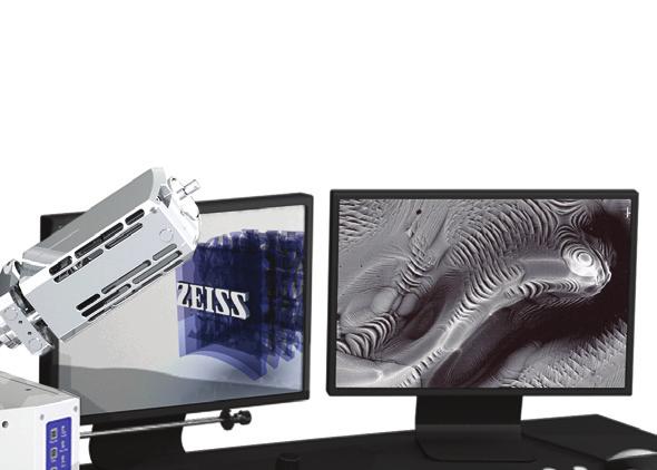
2 ORION NanoFab: An Overview of Applications Author: Dr. Bipin Singh Carl Zeiss NTS, LLC, USA Date: September 2012 Introduction With the advancement of scientific research, nanofabrication is continually being pushed to its limits. For rapid prototyping and fast turnaround, gallium focused ion beam (FIB) based instruments are often used. These charged particle instruments offer the greatest flexibility and the highest throughput for prototyping customized devices for research and development as well as industrial applications. A new entrant in the field of nanofabrication is the ORION NanoFab, an inert ion species based focused ion beam instrument made by Carl Zeiss. Just like a gallium FIB, helium and neon ions can be used for nanofabrication. However, unlike gallium, features made with helium and neon can go down to few nanometers. In addition, the helium ion beam can be used to generate high resolution images of the samples in the same instrument. In this white paper, an overview of applications enabled by this instrument will be provided. The helium or neon focused ion beam is then typically rastered across a sample surface using beam steering electronics to either image the sample or to fabricate structures and devices. Multi-Ion Beams of the ORION NanoFab The ORION NanoFab is the only tool of its kind. It advances the class-leading GFIS technology and features a single column dual beam tool that can generate helium or neon focused ion beam (one at a time) in the same GFIS column. In addition, an optional gallium FIB column can be integrated to ORION NanoFab. Thus, ORION NanoFab is the first commercially available multi-ion beam tool featuring helium, neon and gallium FIB capabilities (Figure 1). ORION NanoFab: The Principles of Operation ORION NanoFab is a third generation gas field ion source (GFIS) based machine by Carl Zeiss that offers a selection of helium and neon focused ion beam. The details about the GFIS technology can be found elsewhere. 1 Briefly, a cryogenically cooled sharpened metal tip that is positively biased with respect to a grounded counter electrode is exposed to very low quantities of helium (or neon) under vacuum. A proprietary method is used to modify the metallic tip in situ such that only three atoms remain at the end of the tip. These three atoms are referred to as the trimer. Under large positive bias, the trimer emits three streams of helium (or neon) ions. One of these ion streams is then aligned and focused by the column optics and becomes the helium or neon focused ion beam. Figure 1 A schematic representation of multi-ion beam concept on ORION NanoFab 2
3 Advantages of Ions Over Electrons for Nanofabrication A variety of methods can be used for fabricating devices and prototypes at the nanoscale. A summary of the methods for nanofabrication using electron and focused ion beams can be found elsewhere. 2 The electron beam based systems are used for nanofabrication by mostly the following two methods: (1) electron beam lithography or (2) electron beam induced deposition or etch in presence of precursor reactive gases. Due to their low mass, electrons cannot be used for direct sputtering of materials. Of course at very high voltages (several hundred kv), electron beams gain high enough energy to punch holes in thin membranes and or modify surfaces or materials. However, this process of making features with high energy electrons is time-consuming and hard to control. Electron beam lithography (EBL) involves exposing the photoresist with an electron beam and then depending on the nature of the photoresist (positive or negative tone), the exposed region is either retained or dissolved during the development process. This method is used in many applications such as writing of structures on photomasks for lithography, hard drive manufacturing and prototyping of many types of devices for research and development. Another way in which electron beam can be used for nanofabrication is by using in conjunction with a gas injection system. In a gas injection system, a precursor gas is introduced in a scanning electron microscope system and the electron beam is scanned on a sample. Depending on the precursor gas used, conductive or insulating materials can be selectively deposited in areas that are exposed by electron beam. If a precursor gas such as xenon difluoride is used, substrates can be etched aggressively, again selectively only in areas that are exposed by the electron beam. More details of such systems can be found elsewhere. 3 When considering ions, there are some unique advantages to nanofabrication. With electons, you can only manipulate their energy and current. However, in a machine like ORION NanoFab, in addition to energy and current, the ion species can also be chosen to fit the job to be done. The specific advantages of light ions such as helium will be described in the next section, but it would suffice to state here that by having a choice of ion species, one can perform massive material removal with, let s say, gallium FIB and do very fine milling with helium ion beam. This method of nanofabrication is also known as ion beam milling and the underlying phenomenon is called sputtering. The lithographic patterning with gallium FIB cannot compete with electron beam lithography in the terms of feature-size. However, when one uses helium and neon ions to expose photoresist, patterning is possible at the same length scale as what can be achieved with electron beam lithography. 4,5 In fact, helium and neon are a superior ion species when it comes to lithography. Sub-10 nm dots and lines can be routinely made with helium and neon ion lithography. In sub-10 nm lithography, electron beam lithography suffers significantly from proximity effect. A distinct advantage of helium and neon ion beam lithography is that there is no proximity effect. This means that when fabricating nested structures, the width of features in the center and periphery of the region of interest will be the same. The user can then focus on designing and fabricating nanostructures of choice rather than engineering elaborate dose adjustments to overcome proximity effect. Advantages of Helium and Neon Over Gallium Ions for Nanofabrication Gallium FIB is a tool of choice for rapid-prototyping applications. Gallium FIBs are routinely used to cross-section samples for failure analysis of semiconductor chips and other types of samples, sample preparation for transmission electron microscopy (TEM), mask repair, and integrated chip modification. While great at milling structures larger than 30 nm in size, Ga FIB is not suited for sub-30 nm regime for nanofabrication. Although the probe size can be as low as ca. 2 nm, the smallest feature size made using Ga FIB is rarely below 30 nm due to interaction with the sample that is milled. Neon ions, on the other hand, are lighter than gallium ions and sputter away material at a smaller scale. Helium ions are even lighter and can be used to make very fine nanostructures. The sizes of structures that can be made with neon and helium ions by milling can routinely reach sub-10 nm length scales. A computer software (SRIM) can be used to understand the scattering effects of ion beam in samples. Table 1 compares the sputter yield of 30 kev gallium, neon and helium ions which can give a sense of milling rates with these three ion species. While helium ions cannot be used for ion milling of very large volumes of material, neon ions are quite effective at removing larger quantities of material. For example, Figure 2 shows image of aluminum posts that were cut using a focused neon ion beam. 3

4 When used with a gas injection system (GIS), helium and neon ions deposit finer features than what is possible with gallium ions. The metals deposits are higher quality as they don t have any gallium contamination. In addition, the insulator deposits are of better quality and exhibit higher resistivity as they don t have gallium in the deposit. Imaging Capabilities of ORION NanoFab In addition to the nanofabrication capabilities, ORION NanoFab also offers high resolution imaging. The imaging capabilities of the ORION platform are well-regarded by the scientific community and has resulted in more than 100 scientific publications. Table 1 Comparing the incident ions interactions in aluminum and gold samples. Data derived from the SRIM simulation of 10,000 incident ions at normal incidence. Incident Beam Aluminum Sample Sputter Yield 30 kev He kev Ne kev Ga Gold Sample Sputter Yield There are three attributes to imaging with ORION NanoFab that should be emphasized (1) Imaging of insulating samples ORION NanoFab excels at imaging uncoated insulating samples. Unlike in a scanning electron microscope, the samples accumulate only a positive charge in an ORION NanoFab which is very elegantly neutralized by a built-in electron flood gun. This means that one doesn t need to coat the samples with conductive over coat in order to get nanometerresolution images. (2) Large depth of field The images generated by ORION NanoFab have 5-10 times depth of field as compared to those generated by a high end FE-SEM. If you have a highly three-dimensional sample, this will result in an image that shows all high and low points of the sample in great detail and focus. (3) High resolution surface-sensitive imaging The images generated by ORION NanoFab are sub-nm in resolution which results in immense details in the images that are captured. Due to the interaction physics of helium ion beam and sample, it turns out that secondary electrons are generated from the sample from the top 5 nm only. In addition, these secondary electrons are SE2 only. This results in immense surface sensitivity in the images. Surface details at high resolution can be seen by ORION NanoFab. Figure 2 Milling capabilities on ORION NanoFab demonstrated by cutting of aluminum posts 4
5 ORION NanoFab White Papers The following white papers are available from Carl Zeiss which highlight key capabilities of ORION NanoFab: White Paper: Nano-pore milling This white paper describes how ORION NanoFab can help in fabrication of pores with diameter smaller than 10 nm. White Paper: Helium and Neon Ion Beam Lithography used for helium and neon ion beam lithography. White Paper: Graphene Nano-ribbon patterning used for making large aspect ratio graphene nano-ribbons in single step. Summary ORION NanoFab is the world s first helium ion microscope focused ion beam instrument offered by Carl Zeiss. Built upon the advancement in the class-leading Gas Field Ion Source (GFIS) technology, ORION NanoFab provides a complete sub-10 nanometer nanofabrication and sub-nanometer imaging solution for the industry, government, and academic research laboratories. ORION NanoFab is the world's first instrument to incorporate neon and helium ion beams in single GFIS column with an optional gallium focused ion beam (FIB) column. The neon ion beam offers outstanding machining and nanofabrication capabilities due to higher sputter yields (for ion beam milling) and faster resist exposure (for ion beam lithography). The helium ion beam allows sub-10 nm nanofabrication as well as high resolution imaging capability in the same instrument. The addition of an optional state-of-the-art gallium FIB column makes the ORION NanoFab the most versatile nanofabrication and imaging platform in the world. White Paper: Fabrication of Solid-State Nano-pores for Biomolecule Detection used for making functional DNA sequencing devices. White Paper: Sub-10 nm Nano-machining with Multiple Ion Beams. used for fabrication of a double bow tie plasmonic device using gallium, neon and helium ion beam. White Paper: Plasmonic Device Fabrication used for fabrication of plasmonic device with sub-10 nm gaps. White Paper: Advancing Oil and Gas Exploration used for getting high resolution images of organic porosity and network of nano-pores in shale rock and coal. References: 1 N. P. Economou, J. A. Notte and W. B. Thompson, Scanning 33, 1-7 (2011). 2 Nanofabrication Using Focused Ion and Electron Beams, edited by I. V. Utke et al., Oxford University Press, I. Utke, P. Hoffman and J. Melngailis, Journal of Vacuum Science and Technology B 26, (2008). 4 D. Maas et al., Proceedings of SPIE 7638, (2010) 5 D. Winston et al., Nano Letters 11, (2011). 5

6 facebook.com/zeissmicroscopy twitter.com/zeiss_micro youtube.com/zeissmicroscopy flickr.com/zeissmicro 42_011_017 CZ-09/2012 Design, scope of delivery and technical progress subject to change without notice. Carl Zeiss Microscopy GmbH Carl Zeiss Microscopy GmbH Jena, Germany
Precision Cutting and Patterning of Graphene with Helium Ions. 1.School of Engineering and Applied Sciences, Harvard University, Cambridge MA 02138
 Precision Cutting and Patterning of Graphene with Helium Ions D.C. Bell 1,2, M.C. Lemme 3, L. A. Stern 4, J.R. Williams 1,3, C. M. Marcus 3 1.School of Engineering and Applied Sciences, Harvard University,
Nova 600 NanoLab Dual beam Focused Ion Beam IITKanpur
 Nova 600 NanoLab Dual beam Focused Ion Beam system @ IITKanpur Dual Beam Nova 600 Nano Lab From FEI company (Dual Beam = SEM + FIB) SEM: The Electron Beam for SEM Field Emission Electron Gun Energy : 500
MSN551 LITHOGRAPHY II
 MSN551 Introduction to Micro and Nano Fabrication LITHOGRAPHY II E-Beam, Focused Ion Beam and Soft Lithography Why need electron beam lithography? Smaller features are required By electronics industry:
Bringing mask repair to the next level
 Bringing mask repair to the next level K. Edinger *, K. Wolff, H. Steigerwald, N. Auth, P. Spies, J. Oster, H. Schneider, M. Budach, T. Hofmann, M. Waiblinger Carl Zeiss SMS GmbH - Industriestraße 1, 64380
Vapor-Phase Cutting of Carbon Nanotubes Using a Nanomanipulator Platform
 Vapor-Phase Cutting of Carbon Nanotubes Using a Nanomanipulator Platform MS&T 10, October 18, 2010 Vladimir Mancevski, President and CTO, Xidex Corporation Philip D. Rack, Professor, The University of
UNIT 3. By: Ajay Kumar Gautam Asst. Prof. Dev Bhoomi Institute of Technology & Engineering, Dehradun
 UNIT 3 By: Ajay Kumar Gautam Asst. Prof. Dev Bhoomi Institute of Technology & Engineering, Dehradun 1 Syllabus Lithography: photolithography and pattern transfer, Optical and non optical lithography, electron,
Direct-Write Deposition Utilizing a Focused Electron Beam
 Direct-Write Deposition Utilizing a Focused Electron Beam M. Fischer, J. Gottsbachner, S. Müller, W. Brezna, and H.D. Wanzenboeck Institute of Solid State Electronics, Vienna University of Technology,
TESCAN S New generation of FIB-SEM microscope
 TESCAN S New generation of FIB-SEM microscope rising standards in sample preparation Key Features SEM COLUMN Versatile system for unlimited applications: resolution imaging (0.9 nm at 15 kev, 1.4 nm at
Kavli Workshop for Journalists. June 13th, CNF Cleanroom Activities
 Kavli Workshop for Journalists June 13th, 2007 CNF Cleanroom Activities Seeing nm-sized Objects with an SEM Lab experience: Scanning Electron Microscopy Equipment: Zeiss Supra 55VP Scanning electron microscopes
Gaetano L Episcopo. Scanning Electron Microscopy Focus Ion Beam and. Pulsed Plasma Deposition
 Gaetano L Episcopo Scanning Electron Microscopy Focus Ion Beam and Pulsed Plasma Deposition Hystorical background Scientific discoveries 1897: J. Thomson discovers the electron. 1924: L. de Broglie propose
Outlines 3/12/2011. Vacuum Chamber. Inside the sample chamber. Nano-manipulator. Focused ion beam instrument. 1. Other components of FIB instrument
 Focused ion beam instruments Outlines 1. Other components of FIB instrument 1.a Vacuum chamber 1.b Nanomanipulator 1.c Gas supply for deposition 1.d Detectors 2. Capabilities of FIB instrument Lee Chow
Techniken der Oberflächenphysik (Techniques of Surface Physics)
") Techniken der Oberflächenphysik (Techniques of Surface Physics) Prof. Yong Lei & Dr. Yang Xu (& Liying Liang) Fachgebiet 3D-Nanostrukturierung, Institut für Physik Contact: yong.lei@tu-ilmenau.de; yang.xu@tu-ilmenau.de;
Techniken der Oberflächenphysik (Techniques of Surface Physics) Prof. Yong Lei & Dr. Yang Xu (& Liying Liang) Fachgebiet 3D-Nanostrukturierung, Institut für Physik Contact: yong.lei@tu-ilmenau.de; yang.xu@tu-ilmenau.de;
Fabrication at the nanoscale for nanophotonics
 Fabrication at the nanoscale for nanophotonics Ilya Sychugov, KTH Materials Physics, Kista silicon nanocrystal by electron beam induced deposition lithography Outline of basic nanofabrication methods Devices
Industry needs: Characterisation & Analysis. Prof. Valeria Nicolosi
 Industry needs: Characterisation & Analysis Prof. Valeria Nicolosi Cleanroom Facility Cleanroom Facility Class 100 and 10,000 cleanroom facility. Cleanroom Sample Preparation Substrates are diced Into
Nanostructures Fabrication Methods
 Nanostructures Fabrication Methods bottom-up methods ( atom by atom ) In the bottom-up approach, atoms, molecules and even nanoparticles themselves can be used as the building blocks for the creation of
Accurate detection of interface between SiO 2 film and Si substrate
 Applied Surface Science 253 (2007) 5511 5515 www.elsevier.com/locate/apsusc Accurate detection of interface between SiO 2 film and Si substrate H.X. Qian a, W. Zhou a, *, X.M. Li b, J.M. Miao a, L.E.N.
An environment designed for success
 An environment designed for success The nanofab is a centralized, open-access, training, service, and collaboration facility, focused on academic research and industrial applications in micro- and nanoscale
Table of Content. Mechanical Removing Techniques. Ultrasonic Machining (USM) Sputtering and Focused Ion Beam Milling (FIB)
 Sputtering and Focused Ion Beam Milling (FIB)") Table of Content Mechanical Removing Techniques Ultrasonic Machining (USM) Sputtering and Focused Ion Beam Milling (FIB) Ultrasonic Machining In ultrasonic machining (USM), also called ultrasonic grinding,
Table of Content Mechanical Removing Techniques Ultrasonic Machining (USM) Sputtering and Focused Ion Beam Milling (FIB) Ultrasonic Machining In ultrasonic machining (USM), also called ultrasonic grinding,
Introduction to Electron Beam Lithography
 Introduction to Electron Beam Lithography Boštjan Berčič (bostjan.bercic@ijs.si), Jožef Štefan Institute, Jamova 39, 1000 Ljubljana, Slovenia 1. Introduction Electron Beam Lithography is a specialized
Introduction to Photolithography
 http://www.ichaus.de/news/72 Introduction to Photolithography Photolithography The following slides present an outline of the process by which integrated circuits are made, of which photolithography is
Nanotechnology Fabrication Methods.
 Nanotechnology Fabrication Methods. 10 / 05 / 2016 1 Summary: 1.Introduction to Nanotechnology:...3 2.Nanotechnology Fabrication Methods:...5 2.1.Top-down Methods:...7 2.2.Bottom-up Methods:...16 3.Conclusions:...19
Fabrication and Domain Imaging of Iron Magnetic Nanowire Arrays
 Abstract #: 983 Program # MI+NS+TuA9 Fabrication and Domain Imaging of Iron Magnetic Nanowire Arrays D. A. Tulchinsky, M. H. Kelley, J. J. McClelland, R. Gupta, R. J. Celotta National Institute of Standards
Defense Technical Information Center Compilation Part Notice
 UNCLASSIFIED Defense Technical Information Center Compilation Part Notice ADP013065 TITLE: Two-Dimensional Photonic Crystal Fabrication Using Fullerene Films DISTRIBUTION: Approved for public release,
DISCOVER NEW HORIZONS IN NANO SCALE IMAGING
 Helium Ion Microscope (HIM) from Carl Zeiss DISCOVER NEW HORIZONS IN NANO SCALE IMAGING ZEISS ORION PLUS The revolutionary helium ion microscope for cutting edge imaging applications, providing ultra high
Dual Beam Helios Nanolab 600 and 650
 Dual Beam Helios Nanolab 600 and 650 In the Clean Room facilities of the INA LMA, several lithography facilities permit to pattern structures at the micro and nano meter scale and to create devices. In
Nanoholes for leak metrology
 Vacuum Metrology for Industry Nanoholes for leak metrology Università Degli Studi di Genova, Italy OUTLINE INTRODUCTION FABRICATION OF NANOHOLES GEOMETRICAL CHARACTERIZATION LEAK DEVICES RESULTS: PTB INRIM
Defining quality standards for the analysis of solid samples
 Defining quality standards for the analysis of solid samples Thermo Scientific Element GD Plus Glow Discharge Mass Spectrometer Redefine your quality standards for the elemental analysis of solid samples
Imaging Methods: Scanning Force Microscopy (SFM / AFM)
") Imaging Methods: Scanning Force Microscopy (SFM / AFM) The atomic force microscope (AFM) probes the surface of a sample with a sharp tip, a couple of microns long and often less than 100 Å in diameter.
Imaging Methods: Scanning Force Microscopy (SFM / AFM) The atomic force microscope (AFM) probes the surface of a sample with a sharp tip, a couple of microns long and often less than 100 Å in diameter.
Selected Characterization Techniques
 Selected Characterization Techniques Tip-enhanced Raman spectroscopy Scanning helium ion microscope Magnetic resonance sub-nanometer imaging Terence Kuzma Outline Tip-enhanced Raman spectroscopy (Lecture
Overview of the main nano-lithography techniques
 Overview of the main nano-lithography techniques Soraya Sangiao sangiao@unizar.es Outline Introduction: Nanotechnology. Nano-lithography techniques: Masked lithography techniques: Photolithography. X-ray
GRAPHENE NANOSTUCTURING WITH THE HELIUM ION MICROSCOPE
 GRAPHENE NANOSTUCTURING WITH THE HELIUM ION MICROSCOPE WANG YUE (B.Eng.(Hons.), NUS) A THESIS SUBMITTED FOR THE DEGREE OF DOCTOR OF PHILOSOPHY DEPARTMENT OF ELECTRICAL AND COMPUTER ENGINEERING NATIONAL
LECTURE 5 SUMMARY OF KEY IDEAS
 LECTURE 5 SUMMARY OF KEY IDEAS Etching is a processing step following lithography: it transfers a circuit image from the photoresist to materials form which devices are made or to hard masking or sacrificial
Supplementary Methods A. Sample fabrication
 Supplementary Methods A. Sample fabrication Supplementary Figure 1(a) shows the SEM photograph of a typical sample, with three suspended graphene resonators in an array. The cross-section schematic is
Technologies VII. Alternative Lithographic PROCEEDINGS OF SPIE. Douglas J. Resnick Christopher Bencher. Sponsored by. Cosponsored by.
 PROCEEDINGS OF SPIE Alternative Lithographic Technologies VII Douglas J. Resnick Christopher Bencher Editors 23-26 February 2015 San Jose, California, United States Sponsored by SPIE Cosponsored by DNS
Focused-ion-beam milling based nanostencil mask fabrication for spin transfer torque studies. Güntherodt
 Focused-ion-beam milling based nanostencil mask fabrication for spin transfer torque studies B. Özyilmaz a, G. Richter, N. Müsgens, M. Fraune, M. Hawraneck, B. Beschoten b, and G. Güntherodt Physikalisches
Chapter 10. Nanometrology. Oxford University Press All rights reserved.
 Chapter 10 Nanometrology Oxford University Press 2013. All rights reserved. 1 Introduction Nanometrology is the science of measurement at the nanoscale level. Figure illustrates where nanoscale stands
Application Note. Graphene Characterization by Correlation of Scanning Electron, Atomic Force and Interference Contrast Microscopy
 Graphene Characterization by Correlation of Scanning Electron, Atomic Force and Interference Contrast Microscopy Graphene Characterization by Correlation of Scanning Electron, Atomic Force and Interference
Auger Electron Spectroscopy
 Auger Electron Spectroscopy Auger Electron Spectroscopy is an analytical technique that provides compositional information on the top few monolayers of material. Detect all elements above He Detection
Supplementary Information. Rapid Stencil Mask Fabrication Enabled One-Step. Polymer-Free Graphene Patterning and Direct
 Supplementary Information Rapid Stencil Mask Fabrication Enabled One-Step Polymer-Free Graphene Patterning and Direct Transfer for Flexible Graphene Devices Keong Yong 1,, Ali Ashraf 1,, Pilgyu Kang 1,
Atomic Force/Magnetic Force Microscope
 Atomic Force/Magnetic Force Microscope Veeco Instruments Dimension 3000 SPM with Nanoscope IIIa controller Atomic Force Microscopy Mode Magnetic Force Microscopy Mode Vibration isolation and sound proof
Critical Dimension Uniformity using Reticle Inspection Tool
 Critical Dimension Uniformity using Reticle Inspection Tool b Mark Wylie, b Trent Hutchinson, b Gang Pan, b Thomas Vavul, b John Miller, b Aditya Dayal, b Carl Hess a Mike Green, a Shad Hedges, a Dan Chalom,
Keywords- Focused Ion Beams, Nanostructuring, Polymers, Functionalization, Electron Microscopy, Surface Modification
 THE USE OF FOCUSED ELECTRON AND ION BEAMS FOR THE FUNCTIONALIZATION AND NANOSTRUCTURING OF POLYMER SURFACES 1 MELTEM SEZEN, 2 FERAY BAKAN 1,2 SUNUM Sabanci University Turkey E-mail: 1 meltemsezen@sabanciuniv.edu,
CHARACTERIZATION of NANOMATERIALS KHP
 CHARACTERIZATION of NANOMATERIALS Overview of the most common nanocharacterization techniques MAIN CHARACTERIZATION TECHNIQUES: 1.Transmission Electron Microscope (TEM) 2. Scanning Electron Microscope
Optical Proximity Correction
 Optical Proximity Correction Mask Wafer *Auxiliary features added on mask 1 Overlay Errors + + alignment mask wafer + + photomask plate Alignment marks from previous masking level 2 (1) Thermal run-in/run-out
Final exam: take-home part
 Final exam: take-home part! List five things that can be done to improve this class. Be specific; give much detail.! (You will be penalized only for insulting comments made for no benefit; you will not
Photoresist Profile. Undercut: negative slope, common for negative resist; oxygen diffusion prohibits cross-linking; good for lift-off.
 Photoresist Profile 4-15 Undercut: negative slope, common for negative resist; oxygen diffusion prohibits cross-linking; good for lift-off undercut overcut Overcut: positive slope, common to positive resist,
High speed focused ion (and electron) beam nanofabrication
 beam nanofabrication") High speed focused ion (and electron) beam nanofabrication John Melngailis, Department of Electrical and Computer Engineering and Institute for Research in Electronics and Applied Physics University of
High speed focused ion (and electron) beam nanofabrication John Melngailis, Department of Electrical and Computer Engineering and Institute for Research in Electronics and Applied Physics University of
Nanotechnology Nanofabrication of Functional Materials. Marin Alexe Max Planck Institute of Microstructure Physics, Halle - Germany
 Nanotechnology Nanofabrication of Functional Materials Marin Alexe Max Planck Institute of Microstructure Physics, Halle - Germany Contents Part I History and background to nanotechnology Nanoworld Nanoelectronics
h p λ = mν Back to de Broglie and the electron as a wave you will learn more about this Equation in CHEM* 2060
 Back to de Broglie and the electron as a wave λ = mν h = h p you will learn more about this Equation in CHEM* 2060 We will soon see that the energies (speed for now if you like) of the electrons in the
CBE Science of Engineering Materials. Scanning Electron Microscopy (SEM)
") CBE 30361 Science of Engineering Materials Scanning Electron Microscopy (SEM) Scale of Structure Organization Units: micrometer = 10-6 m = 1µm nanometer= 10-9 m = 1nm Angstrom = 10-10 m = 1Å A hair is
CBE 30361 Science of Engineering Materials Scanning Electron Microscopy (SEM) Scale of Structure Organization Units: micrometer = 10-6 m = 1µm nanometer= 10-9 m = 1nm Angstrom = 10-10 m = 1Å A hair is
Low Temperature (LT), Ultra High Vacuum (UHV LT) Scanning Probe Microscopy (SPM) Laboratory
, Ultra High Vacuum (UHV LT) Scanning Probe Microscopy (SPM) Laboratory") Low Temperature (LT), Ultra High Vacuum (UHV LT) Scanning Probe Microscopy (SPM) Laboratory The laboratory of Low Temperature, Ultra High Vacuum (UHV LT) is specifically designed for surface science microscopy
Low Temperature (LT), Ultra High Vacuum (UHV LT) Scanning Probe Microscopy (SPM) Laboratory The laboratory of Low Temperature, Ultra High Vacuum (UHV LT) is specifically designed for surface science microscopy
Supplementary Figure 1 Detailed illustration on the fabrication process of templatestripped
 Supplementary Figure 1 Detailed illustration on the fabrication process of templatestripped gold substrate. (a) Spin coating of hydrogen silsesquioxane (HSQ) resist onto the silicon substrate with a thickness
Focused Ion Beam Nanofabrication
 Focused Ion Beam / Focused Electron Beam NT II - 2007 Focused Ion Beam Nanofabrication Nanotechnology for Engineers : J. Brugger (LMIS-1) & P. Hoffmann (IOA) Nova 600 NANOLAB (FEI) Dual-Beam Instrument
Chapter 9. Electron mean free path Microscopy principles of SEM, TEM, LEEM
 Chapter 9 Electron mean free path Microscopy principles of SEM, TEM, LEEM 9.1 Electron Mean Free Path 9. Scanning Electron Microscopy (SEM) -SEM design; Secondary electron imaging; Backscattered electron
TRANSVERSE SPIN TRANSPORT IN GRAPHENE
 International Journal of Modern Physics B Vol. 23, Nos. 12 & 13 (2009) 2641 2646 World Scientific Publishing Company TRANSVERSE SPIN TRANSPORT IN GRAPHENE TARIQ M. G. MOHIUDDIN, A. A. ZHUKOV, D. C. ELIAS,
NANONICS IMAGING FOUNTAIN PEN
 NANONICS IMAGING FOUNTAIN PEN NanoLithography Systems Methods of Nanochemical Lithography Fountain Pen NanoLithography A. Lewis et al. Appl. Phys. Lett. 75, 2689 (1999) FPN controlled etching of chrome.
Scanning Electron Microscopy
 Scanning Electron Microscopy Field emitting tip Grid 2kV 100kV Anode ZEISS SUPRA Variable Pressure FESEM Dr Heath Bagshaw CMA bagshawh@tcd.ie Why use an SEM? Fig 1. Examples of features resolvable using
Ecole Franco-Roumaine : Magnétisme des systèmes nanoscopiques et structures hybrides - Brasov, Modern Analytical Microscopic Tools
 1. Introduction Solid Surfaces Analysis Group, Institute of Physics, Chemnitz University of Technology, Germany 2. Limitations of Conventional Optical Microscopy 3. Electron Microscopies Transmission Electron
Nano fabrication by e-beam lithographie
 Introduction to nanooptics, Summer Term 2012, Abbe School of Photonics, FSU Jena, Prof. Thomas Pertsch Nano fabrication by e-beam lithographie Lecture 14 1 Electron Beam Lithography - EBL Introduction
Enhanced High Aspect Ratio Etch Performance With ANAB Technology. Keywords: High Aspect Ratio, Etch, Neutral Particles, Neutral Beam I.
 Enhanced High Aspect Ratio Etch Performance With ANAB Technology. Keywords: High Aspect Ratio, Etch, Neutral Particles, Neutral Beam I. INTRODUCTION As device density increases according to Moore s law,
Top down and bottom up fabrication
 Lecture 24 Top down and bottom up fabrication Lithography ( lithos stone / graphein to write) City of words lithograph h (Vito Acconci, 1999) 1930 s lithography press Photolithography d 2( NA) NA=numerical
DISCOVER NEW HORIZONS IN NANO SCALE IMAGING
 Carl Zeiss SMT Nano Technology Systems Division DISCOVER NEW HORIZONS IN NANO SCALE IMAGING ZEISS ORION PLUS The revolutionary helium ion microscope for cutting edge imaging applications, providing ultra
Auger Electron Spectroscopy Overview
 Auger Electron Spectroscopy Overview Also known as: AES, Auger, SAM 1 Auger Electron Spectroscopy E KLL = E K - E L - E L AES Spectra of Cu EdN(E)/dE Auger Electron E N(E) x 5 E KLL Cu MNN Cu LMM E f E
Simulation of Ion Beam Etching of Patterned Nanometer-scale Magnetic Structures for High-Density Storage Applications
 Engineered Excellence A Journal for Process and Device Engineers Simulation of Ion Beam Etching of Patterned Nanometer-scale Magnetic Structures for High-Density Storage Applications Introduction Fabrication
ION SOURCES FOR NANOFABRICATION AND HIGH RESOLUTION LITHOGRAPHY
 ON SOURCES FOR NANOFABRCATON AND HGH RESOLUTON LTHOGRAPHY J. Melngailis,* University of Maryland, College Park, MD 20742-3511, USA Abstract on sources that are used to produce nanometer resolution patterns
Ice Lithography for Nano-Devices
 Ice Lithography for Nano-Devices Anpan Han 1, Dimitar Vlassarev 1, Jenny Wang 1, Jene A. Golovchenko 1,2 and Daniel Branton 3 * 1 Department of Physics, Harvard University, Cambridge, MA 02138, USA. 2
Sub-5 nm Patterning and Applications by Nanoimprint Lithography and Helium Ion Beam Lithography
 Sub-5 nm Patterning and Applications by Nanoimprint Lithography and Helium Ion Beam Lithography Yuanrui Li 1, Ahmed Abbas 1, Yuhan Yao 1, Yifei Wang 1, Wen-Di Li 2, Chongwu Zhou 1 and Wei Wu 1* 1 Department
Measurement of the role of secondary electrons in EUV resist exposures
 Measurement of the role of secondary electrons in EUV resist exposures June 12, 213 International Workshop on EUV Lithography Greg Denbeaux a, Justin Torok, a Ryan Del Re, a Henry Herbol, a Sanjana Das,
We are IntechOpen, the world s leading publisher of Open Access books Built by scientists, for scientists. International authors and editors
 We are IntechOpen, the world s leading publisher of Open Access books Built by scientists, for scientists 3,800 116,000 120M Open access books available International authors and editors Downloads Our
High Yield Structured X-ray Photo-Cathode Development and Fabrication
 High Yield Structured X-ray Photo-Cathode Development and Fabrication K. Opachich 1, P. Ross 1, J. Koch 1, A. MacPhee 2, O. Landen 2, D. Bradley 2, P. Bell 2, S. Nagel 2, T. Hilsabeck 4, N. Chen 5, S.
 Ion beam lithography Progress in ion technology spot size
 FOCUSSED ION BEAM ASSISTED THREE-DIMENSIONAL ROCK IMAGING AT SUBMICRON SCALE
 FOCUSSED ION BEAM ASSISTED THREE-DIMENSIONAL ROCK IMAGING AT SUBMICRON SCALE 1 Liviu Tomutsa and 2 Velimir Radmilovic 1 Earth Science Division and 2 National Center for Electron Microscopy, Lawrence Berkeley
ETCHING Chapter 10. Mask. Photoresist
 ETCHING Chapter 10 Mask Light Deposited Substrate Photoresist Etch mask deposition Photoresist application Exposure Development Etching Resist removal Etching of thin films and sometimes the silicon substrate
Sensors and Metrology. Outline
 Sensors and Metrology A Survey 1 Outline General Issues & the SIA Roadmap Post-Process Sensing (SEM/AFM, placement) In-Process (or potential in-process) Sensors temperature (pyrometry, thermocouples, acoustic
Using Calibrated Specular Reflectance Standards for Absolute and Relative Reflectance Measurements
 Using Calibrated Specular Reflectance Standards for Absolute and Relative Reflectance Measurements Applications Overview here are two fundamental techniques for measuring specular reflectance with a UV/VIS/NIR
MEEN Nanoscale Issues in Manufacturing. Lithography Lecture 1: The Lithographic Process
 MEEN 489-500 Nanoscale Issues in Manufacturing Lithography Lecture 1: The Lithographic Process 1 Discuss Reading Assignment 1 1 Introducing Nano 2 2 Size Matters 3 3 Interlude One-The Fundamental Science
1. Introduction : 1.2 New properties:
 Nanodevices In Electronics Rakesh Kasaraneni(PID : 4672248) Department of Electrical Engineering EEL 5425 Introduction to Nanotechnology Florida International University Abstract : This paper describes
Chapter 12. Nanometrology. Oxford University Press All rights reserved.
 Chapter 12 Nanometrology Introduction Nanometrology is the science of measurement at the nanoscale level. Figure illustrates where nanoscale stands in relation to a meter and sub divisions of meter. Nanometrology
UNIVERSITY OF CALIFORNIA College of Engineering Department of Electrical Engineering and Computer Sciences. Fall Exam 1
 UNIVERSITY OF CALIFORNIA College of Engineering Department of Electrical Engineering and Computer Sciences EECS 143 Fall 2008 Exam 1 Professor Ali Javey Answer Key Name: SID: 1337 Closed book. One sheet
Supplementary Information. Characterization of nanoscale temperature fields during electromigration of nanowires
 Supplementary Information Characterization of nanoscale temperature fields during electromigration of nanowires Wonho Jeong,, Kyeongtae Kim,, *, Youngsang Kim,, Woochul Lee,, *, Pramod Reddy Department
Nanomachining by focused ion beam
 Nanomachining by focused ion beam Thesis Horváth Enikő Supervisor: Dr. Tóth Attila Lajos Consultant: Dr. Kocsányi László RESEARCH INSTITUTE FOR TECHNICAL PHYSICS AND MATERIALS SCIENCE Budapest 2009 Outline
MEMS Metrology. Prof. Tianhong Cui ME 8254
 MEMS Metrology Prof. Tianhong Cui ME 8254 What is metrology? Metrology It is the science of weights and measures Refers primarily to the measurements of length, weight, time, etc. Mensuration- A branch
Thermal Resistance Measurement
 Optotherm, Inc. 2591 Wexford-Bayne Rd Suite 304 Sewickley, PA 15143 USA phone +1 (724) 940-7600 fax +1 (724) 940-7611 www.optotherm.com Optotherm Sentris/Micro Application Note Thermal Resistance Measurement
There's Plenty of Room at the Bottom
 There's Plenty of Room at the Bottom 12/29/1959 Feynman asked why not put the entire Encyclopedia Britannica (24 volumes) on a pin head (requires atomic scale recording). He proposed to use electron microscope
How to distinguish EUV photons from out-of-band photons
 How to distinguish EUV photons from out-of-band photons Thesis submitted in partial fulfillment of the requirements for the degree of Master of Science in Physics Author: Student ID: Supervisors: 2 nd
Nanostrukturphysik (Nanostructure Physics)
") Nanostrukturphysik (Nanostructure Physics) Prof. Yong Lei & Dr. Yang Xu Fachgebiet 3D-Nanostrukturierung, Institut für Physik Contact: yong.lei@tu-ilmenau.de; yang.xu@tu-ilmenau.de Office: Unterpoerlitzer
Nanostrukturphysik (Nanostructure Physics) Prof. Yong Lei & Dr. Yang Xu Fachgebiet 3D-Nanostrukturierung, Institut für Physik Contact: yong.lei@tu-ilmenau.de; yang.xu@tu-ilmenau.de Office: Unterpoerlitzer
Ionic Liquid Ion Sources in the Processing of Materials and Other Applications
 Ionic Liquid Ion Sources in the Processing of Materials and Other Applications Paulo Lozano Massachusetts Institute of Technology Materials and Processes Far From Equilibrium Workshop November 3, 2010
Fabrication-II. Electron Beam Lithography Pattern Design Thin Film Deposition
 Fabrication-II Electron Beam Lithography Pattern Design Thin Film Deposition By Charulata Barge, Graduate student, Prof. Zumbühl Group, Department of Physics, Universtity of Basel. Date:- 20th Oct. 2006
Table of Contents. Foreword... Jörge DE SOUSA NORONHA. Introduction... Michel BRILLOUËT
 Table of Contents Foreword... Jörge DE SOUSA NORONHA Introduction... Michel BRILLOUËT xi xvii Chapter 1. Photolithography... 1 Philippe BANDELIER, Anne-Laure CHARLEY and Alexandre LAGRANGE 1.1. Introduction...
Lecture 0: Introduction
 Lecture 0: Introduction Introduction q Integrated circuits: many transistors on one chip q Very Large Scale Integration (VLSI): bucketloads! q Complementary Metal Oxide Semiconductor Fast, cheap, low power
Sensors and Metrology
 Sensors and Metrology A Survey 1 Outline General Issues & the SIA Roadmap Post-Process Sensing (SEM/AFM, placement) In-Process (or potential in-process) Sensors temperature (pyrometry, thermocouples, acoustic
Chromeless Phase Lithography (CPL)
") Chromeless Phase Lithography (CPL) Chromeless Phase Lithography or CPL is a recent development in the area of phase shifting technology that is extending the perceived k 1 limits and has the potential
Chromeless Phase Lithography (CPL) Chromeless Phase Lithography or CPL is a recent development in the area of phase shifting technology that is extending the perceived k 1 limits and has the potential
Supplementary Information. Back-Contacted Hybrid Organic-Inorganic Perovskite Solar Cells
 Electronic Supplementary Material (ESI) for Journal of Materials Chemistry C. This journal is The Royal Society of Chemistry 2016 Journal of Materials Chemistry C Supplementary Information Back-Contacted
Nanoscale Issues in Materials & Manufacturing
 Nanoscale Issues in Materials & Manufacturing ENGR 213 Principles of Materials Engineering Module 2: Introduction to Nanoscale Issues Top-down and Bottom-up Approaches for Fabrication Winfried Teizer,
Fabrication of Sub-10 nm Metallic Structures via Nanomasking Technique for Plasmonic Enhancement Applications
 Fabrication of Sub-10 nm Metallic Structures via Nanomasking Technique for Plasmonic Enhancement Applications A thesis submitted in partial fulfillment of the requirements for the degree of Master of Science
A Novel Approach to the Layer Number-Controlled and Grain Size- Controlled Growth of High Quality Graphene for Nanoelectronics
 Supporting Information A Novel Approach to the Layer Number-Controlled and Grain Size- Controlled Growth of High Quality Graphene for Nanoelectronics Tej B. Limbu 1,2, Jean C. Hernández 3, Frank Mendoza
Gold nanothorns macroporous silicon hybrid structure: a simple and ultrasensitive platform for SERS
 Supporting Information Gold nanothorns macroporous silicon hybrid structure: a simple and ultrasensitive platform for SERS Kamran Khajehpour,* a Tim Williams, b,c Laure Bourgeois b,d and Sam Adeloju a
Supplementary Figure S1. AFM images of GraNRs grown with standard growth process. Each of these pictures show GraNRs prepared independently,
 Supplementary Figure S1. AFM images of GraNRs grown with standard growth process. Each of these pictures show GraNRs prepared independently, suggesting that the results is reproducible. Supplementary Figure
ALIGNMENT ACCURACY IN A MA/BA8 GEN3 USING SUBSTRATE CONFORMAL IMPRINT LITHOGRAPHY (SCIL)
") ALIGNMENT ACCURACY IN A MA/BA8 GEN3 USING SUBSTRATE CONFORMAL IMPRINT LITHOGRAPHY (SCIL) Robert Fader Fraunhofer Institute for Integrated Systems and Device Technology (IISB) Germany Ulrike Schömbs SUSS
ALIGNMENT ACCURACY IN A MA/BA8 GEN3 USING SUBSTRATE CONFORMAL IMPRINT LITHOGRAPHY (SCIL) Robert Fader Fraunhofer Institute for Integrated Systems and Device Technology (IISB) Germany Ulrike Schömbs SUSS
Nano fabrication and optical characterization of nanostructures
 Introduction to nanooptics, Summer Term 2012, Abbe School of Photonics, FSU Jena, Prof. Thomas Pertsch Nano fabrication and optical characterization of nanostructures Lecture 12 1 Optical characterization