Strengthening of columns with FRP
|
|
|
- Virginia Simmons
- 5 years ago
- Views:
Transcription


1 with FRP Professor Dr. Björn Täljsten Luleå University of Technology Sto Scandinavia AB 9/12/2013
2 Agenda Case study Restrained transverse expansion (confinement) Circular and rectangular cross sections A simplified approach for combined normal force and flexure An example for calculation


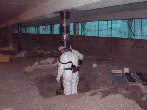
3 Case study Parking garage
.")
4 Case study Parking garage Object: KV Smedby Repair and upgrading of 96 concrete columns due to chloride intrusion and corroded reinforcement - maintaining and increasing load capacity Measure: Repair with StoCrete TK samt StoCrete GM1 (EN1504-3). Sawing grooves for StoFRP Bar E10C (flexural strengthening) Surface preparation and mounting of StoFRP Sheet (confinement strengthening)

5 Case study Parking garage Mounting CFRP bars (StoFRP Bar E10C) in sawed grooves and bonding with epoxy adhesive (StoBPE Lim 567)
 Bonded with an epoxy adhesive (StoBPE Lim 417) - Flexural")
6 Case study Parking garage Mounting carbon fibre sheets in the longitudinal direction (StoFRP Sheet S300C300) Bonded with an epoxy adhesive (StoBPE Lim 417) - Flexural strengthening


 -")
7 Case study Parking garage Mounting of transverse carbon fibre sheets (StoFRP S300C300) Bonding (StoBPE Lim 417) - Confinement strengthening

8 Confinement effect Case study Parking garage


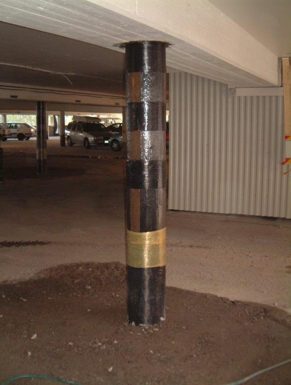
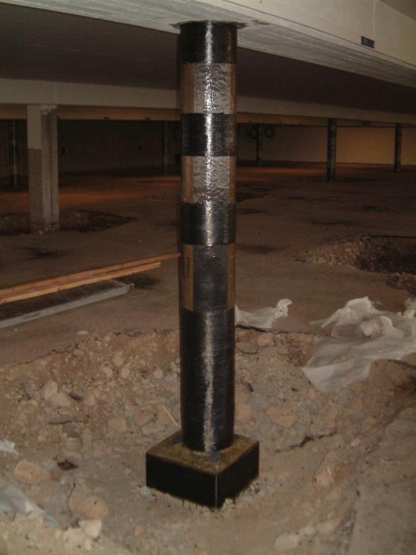
9 End result Case study Parking garage
10 Restrained transverse expansion - Lateral confinement 1 =f ck,c r r = f l r E f t f fe E f t f fe E f t f t E f t f t
11 Confinement effect The lateral confinement pressure, r 1 =f ck,c r 2 Ef t f t r d r E f t f t E f modulus of elasticity for fibres or FRP t f thickness of fibres or FRP t is the transversal strain E f t f t
12 Confinement effect The maximum lateral confinement, f l 1 =f ck,c r f l 2E f t f t, rup d r E f t f t E f modulus of elasticity for fibres or FRP t f thickness of fibres or FRP t,rup is the transversal strain at rupture E f t f t
13 Confinement effect The maximum transverse strain, t,rup 1 =f ck,c r fu t,rup r Curvature of the FRP jacket (wrapping) The deformation localisation of the cracked concrete The existence of an overlapping zone (The biaxial stress state that the jacket is subjected to) E f t f t E f t f t
14 Confinement effect A reasonable and accurate stress-strain model for the FRP confined concrete must be based on the actual transverse rupture strain of the FRP Ascending type Descending type f c f c,c f c,c f c,cu c,c cu,c cu,c c
15 Confinement effect The most established models for describing the restrained transverse confinement are: ACI 440.2R (2008) [US] Fib bulletin 14 (2001) [international] CSA (2002) [Canadian Standards Association) Eurocode 2, , (2008) [Europe]
16 Confinement effect Comparison of different models, confinement effect: 2 = 2 MPa f ck = 30 MPa
17 Confinement effect Comparison of different models, confinement effect: 2 = 8 MPa f ck = 30 MPa
18 Centric compression Axial stresses and strain (no eccentricity) 2 Ec E2 2 c Ecc c 0c t 4 f ck f E c ck 2 c t c cu, c Parabolic Linear t E 2 f ck c E 2 c f c,c Intersection E 2 E 2 f ck, c cu, c f ck t cu,c c
19 Centric compression Maximum confinement pressure f f 33 f cd, c cd f, c. a l Design compressive strength f l 2 E f nt f fe D Maximum confinement pressure a Efficiency factor, considering shape and geometry fe Effective strain (ultimate state for FRP system)
20 Centric compression Effective strain fe fu Efficiency factor considering FRP premature failure due to the triaxial state of stress (relation between actual failure strain and ultimate coupon failure strain). Correlations to test gives a value of 0.55.
21 Centric compression Avoiding descending stress strain behaviour f f l ck 0.08 In order to assure that the confinement effects keeps increasing, ascending linearly.
22 Centric compression The maximum compression strain in confined concrete (f ck <70 MPa) 0.45 f l fe cu, c c b 10 fck c2 To avoid excessive crack formation and to secure the integrity of the concrete cross section. Calculated in. b Efficiency factor considering the geometry of the cross section
23 Circular cross section The confinement effect is largest for circular cross sections a a 1.0 Shape/geometry factors
24 Non circular cross sections Experimental results indicate that the confinement effect is much less for non circular cross sections (e.g. rectangular cross sections). Larger the cross sections less effect. h b 2 b and h 900mm Limitations
25 Non circular cross sections The maximum confinement pressure corresponds to an area bound by an equivalent circular cross section. h Diameter 2 2 D b h b D r c
26 Non circular cross sections The maximum confinement pressure corresponds to an area bound by an equivalent circular cross section. h Geometrical efficiency factors (depending on the effective confinement area and the side ratio b/h) b D r c a Ace b A h c 2 b Ace b A h c 0.5
27 Non circular cross sections The maximum confinement pressure corresponds to an area bound by an equivalent circular cross section. h Effective confinement area (depending on the rounding of the corners, the side ratio b/h AND the reinforcement ratio) b D r c A A ce c 1 b h h b 3A h2r b 2r c 2 2 c g 1 g g
28 Interaction between normal forces (N) and flexure (M) Simplified approach N D D Med omslutningseffekt Utan omslutningseffekt Dimensionerande last, N och M Limitations: Slenderness ratio, l lim 50 The effective strain B B fe fu A M -N
29 Interaction between normal forces (N) and flexure (M) cök cu s2,d > sy Simplified approach Nc D s1,d > sy cuk = cu C cök = cu s2,c NL s1,c < sy cök = cu cuk s2,b A B M cök = cu NL s1,b = sy cuk s2,a NL Nt s1,a > sy cuk
30 Example, confinement Rectangular cross section, increase of normal force by 15% (current capacity 3000 kn). Geometrical properties d2 A s2 0.5d Value Unit Description b = h 400 mm Side of column P d 1 = 40 mm Concrete cover h G d 2 = 40 mm Concrete cover dpg d1 A s1 b h/2 A s1 = 1256 mm 2 Reinforcement area A s2 = 1256 mm 2 Reinforcement area A c = mm 2 Concrete area (no reinforcement) A g = mm 2 Gross sectional area
31 Example, confinement Rectangular cross section, increase of normal force by 15% (current capacity 3000 kn). Geometrical properties d2 A s2 0.5d Value Unit Description b = h 400 mm Side of column P d 1 = 40 mm Concrete cover h G d 2 = 40 mm Concrete cover dpg d1 A s1 b h/2 A s1 = 1256 mm 2 Reinforcement area A s2 = 1256 mm 2 Reinforcement area A c = mm 2 Concrete area (no reinforcement) A g = mm 2 Gross sectional area
32 Example, confinement Rectangular cross section, increase of normal force by 15% (current capacity 3000 kn). Reduction factors in ULS h d2 A s2 P G 0.5d Concrete Steel FRP g c =1.5 g s =1.15 g frp =1.35 cc =0.85 ct =0.85 dpg A s1 h/2 φ ef =2.0 d1 b g ce =1.2
33 Example, confinement Rectangular cross section, increase of normal force by 20% (current capacity 3300 kn). Material properties h d2 dpg A s2 A s1 P G 0.5d h/2 C o n c r e t e Characteristic values S Characteristic values f ck 25 MPa t e f yk 500 MPa f ctm 2.2 MPa e l E s 210 GPa E cm 31 GPa d1 b C o n c r e t e Design values S Design values f cd 14 MPa t e f yd 435 MPa f ctm 2.2 MPa e l E sd 183 GPa
34 Example, confinement Estimate the confinement effect, using a carbon fibre sheet with a thickness of 0.17mm (300g/m 2 ) Mechanical properties for sheet d2 A s2 P 0.5d FRP Characteristic values Design values fk 19 f 14.1 E fk 290 GPa E f GPa h G dpg A s1 h/2 d1 b
35 Example, confinement Step 1. Calculate the geometrical factors D b 2 h mm A ce A c b 1 h h b 3A h 2r b 2r c 2 2 g 1 g c g
36 Example, confinement Step 1. Calculate the geometrical factors 2 2 Ace b 400 a A h 400 c b A A ce c b h e fe Normal loading only min 0.004, fe e f Considering N-M interaction and shear capacity integrity
37 Example, confinement Step 2. Calculate the confinement pressure, normal force only Choose the number of layers, n = 4 f l 2E f nt f fe MPa D 566 fcd, c fcd f, c3.3a fl ,2 MPa Strengthened normal force capacity: 4347 kn > 3800 kn OK!
38 Example, confinement Step 2. Calculate the confinement pressure, considering possible N-M interaction Choose the number of layers, n = 6 f l 2E f nt f fe MPa D 566 fcd, c fcd f, c3.3a fl MPa Strengthened normal force capacity: 4072 kn > 3800 kn OK!
ASSESSMENT OF NONLINEAR BOND LAWS FOR NEAR- SURFACE-MOUNTED SYSTEMS IN CONCRETE ELEMENTS
 ASSESSMENT OF NONLINEAR BOND LAWS FOR NEAR- SURFACE-MOUNTED SYSTEMS IN CONCRETE ELEMENTS Francesca CERONI* Assistant Professor Engineering Department, University of Sannio Piazza Roma, 21, 82100 - Benevento,
Bending and Shear in Beams
 Bending and Shear in Beams Lecture 3 5 th October 017 Contents Lecture 3 What reinforcement is needed to resist M Ed? Bending/ Flexure Section analysis, singly and doubly reinforced Tension reinforcement,
Standardisation of UHPC in Germany
 Standardisation of UHPC in Germany Part II: Development of Design Rules, University of Siegen Prof. Dr.-Ing. Ekkehard Fehling, University of Kassel 1 Overvie Introduction: Work of the Task Group Design
Design of reinforced concrete sections according to EN and EN
 Design of reinforced concrete sections according to EN 1992-1-1 and EN 1992-2 Validation Examples Brno, 21.10.2010 IDEA RS s.r.o. South Moravian Innovation Centre, U Vodarny 2a, 616 00 BRNO tel.: +420-511
POST-PEAK BEHAVIOR OF FRP-JACKETED REINFORCED CONCRETE COLUMNS
 POST-PEAK BEHAVIOR OF FRP-JACKETED REINFORCED CONCRETE COLUMNS - Technical Paper - Tidarut JIRAWATTANASOMKUL *1, Dawei ZHANG *2 and Tamon UEDA *3 ABSTRACT The objective of this study is to propose a new
FRP Seismic Strengthening of Columns in Frames
 FRP Seismic Strengthening of Columns in Frames Dr Mihaela-Anca Ciupala (EU Marie Curie Research Fellow) Dr Kypros Pilakoutas (Reader) Professor Nicolae Taranu Centre for Cement and Concrete Department
CHAPTER 4. ANALYSIS AND DESIGN OF COLUMNS
 4.1. INTRODUCTION CHAPTER 4. ANALYSIS AND DESIGN OF COLUMNS A column is a vertical structural member transmitting axial compression loads with or without moments. The cross sectional dimensions of a column
Earthquake-resistant design of indeterminate reinforced-concrete slender column elements
 Engineering Structures 29 (2007) 163 175 www.elsevier.com/locate/engstruct Earthquake-resistant design of indeterminate reinforced-concrete slender column elements Gerasimos M. Kotsovos a, Christos Zeris
DEFORMATION CAPACITY OF OLDER RC SHEAR WALLS: EXPERIMENTAL ASSESSMENT AND COMPARISON WITH EUROCODE 8 - PART 3 PROVISIONS
 DEFORMATION CAPACITY OF OLDER RC SHEAR WALLS: EXPERIMENTAL ASSESSMENT AND COMPARISON WITH EUROCODE 8 - PART 3 PROVISIONS Konstantinos CHRISTIDIS 1, Emmanouil VOUGIOUKAS 2 and Konstantinos TREZOS 3 ABSTRACT
Consequently, retrofit of many poor existing structures is a very important issue. for Turkey!
 Turkey Placed on one of the most active tectonic plates in the world ~96% of the country is under the threat of earthquakes ~98% of the population are live with that risk. Istanbul 1 st degree of earthquake
ε t increases from the compressioncontrolled Figure 9.15: Adjusted interaction diagram
 CHAPTER NINE COLUMNS 4 b. The modified axial strength in compression is reduced to account for accidental eccentricity. The magnitude of axial force evaluated in step (a) is multiplied by 0.80 in case
Reinforced concrete structures II. 4.5 Column Design
 4.5 Column Design A non-sway column AB of 300*450 cross-section resists at ultimate limit state, an axial load of 700 KN and end moment of 90 KNM and 0 KNM in the X direction,60 KNM and 27 KNM in the Y
This is a repository copy of Nominal Curvature Design of Circular HSC Columns Confined with Post-tensioned Steel Straps.
 This is a repository copy of Nominal Curvature Design of Circular HSC Columns Confined with Post-tensioned Steel Straps. White Rose Research Online URL for this paper: http://eprints.whiterose.ac.uk/99872/
A PROPOSAL OF DESIGN PROCEDURE FOR FLEXURAL STRENGTHENING RC BEAMS WITH FRP SHEET
 N. Kishi, E-89, 1/8 A PROPOSAL OF DESIGN PROCEDURE FOR FLEXURAL STRENGTHENING RC BEAMS WITH FRP SHEET Yusuke Kurihashi Norimitsu Kishi Hiroshi Mikami Sumiyuki Sawada Civil Engrg. Research Muroran Inst.
Reinforced Concrete Structures
 Reinforced Concrete Structures MIM 232E Dr. Haluk Sesigür I.T.U. Faculty of Architecture Structural and Earthquake Engineering WG Ultimate Strength Theory Design of Singly Reinforced Rectangular Beams
Flexure: Behavior and Nominal Strength of Beam Sections
 4 5000 4000 (increased d ) (increased f (increased A s or f y ) c or b) Flexure: Behavior and Nominal Strength of Beam Sections Moment (kip-in.) 3000 2000 1000 0 0 (basic) (A s 0.5A s ) 0.0005 0.001 0.0015
EUROCODE EN SEISMIC DESIGN OF BRIDGES
 Brussels, 18-20 February 2008 Dissemination of information workshop 1 EUROCODE EN1998-2 SEISMIC DESIGN OF BRIDGES Basil Kolias Basic Requirements Brussels, 18-20 February 2008 Dissemination of information
Chapter. Materials. 1.1 Notations Used in This Chapter
 Chapter 1 Materials 1.1 Notations Used in This Chapter A Area of concrete cross-section C s Constant depending on the type of curing C t Creep coefficient (C t = ε sp /ε i ) C u Ultimate creep coefficient
Seismic Pushover Analysis Using AASHTO Guide Specifications for LRFD Seismic Bridge Design
 Seismic Pushover Analysis Using AASHTO Guide Specifications for LRFD Seismic Bridge Design Elmer E. Marx, Alaska Department of Transportation and Public Facilities Michael Keever, California Department
CE5510 Advanced Structural Concrete Design - Design & Detailing of Openings in RC Flexural Members-
 CE5510 Advanced Structural Concrete Design - Design & Detailing Openings in RC Flexural Members- Assoc Pr Tan Kiang Hwee Department Civil Engineering National In this lecture DEPARTMENT OF CIVIL ENGINEERING
Design of AAC wall panel according to EN 12602
 Design of wall panel according to EN 160 Example 3: Wall panel with wind load 1.1 Issue Design of a wall panel at an industrial building Materials with a compressive strength 3,5, density class 500, welded
FRACTURE MECHANICS APPROACHES STRENGTHENING USING FRP MATERIALS
 Fracture Mechanics of Concrete Structures Proceedings FRAMCOS-3 AEDIFICATIO Publishers, D-79104 Freiburg, Germany FRACTURE MECHANICS APPROACHES STRENGTHENING USING FRP MATERIALS Triantafillou Department
Example 4.1 [Uni-axial Column Design] Solution. Step 1- Material Step 2-Determine the normalized axial and bending moment value
![Example 4.1 [Uni-axial Column Design] Solution. Step 1- Material Step 2-Determine the normalized axial and bending moment value](/thumbs/75/72436916.jpg "Example 4.1 [Uni-axial Column Design] Solution. Step 1- Material Step 2-Determine the normalized axial and bending moment value") Example 4.1 [Uni-axial Column Design] 1. Design the braced short column to sustain a design load of 1100 KN and a design moment of 160KNm which include all other effects.use C5/30 and S460 class 1 works
Example 4.1 [Uni-axial Column Design] 1. Design the braced short column to sustain a design load of 1100 KN and a design moment of 160KNm which include all other effects.use C5/30 and S460 class 1 works
MECHANICS OF MATERIALS Sample Problem 4.2
 Sample Problem 4. SOLUTON: Based on the cross section geometry, calculate the location of the section centroid and moment of inertia. ya ( + Y Ad ) A A cast-iron machine part is acted upon by a kn-m couple.
INTRODUCTION TO STRAIN
 SIMPLE STRAIN INTRODUCTION TO STRAIN In general terms, Strain is a geometric quantity that measures the deformation of a body. There are two types of strain: normal strain: characterizes dimensional changes,
Lap splice length and details of column longitudinal reinforcement at plastic hinge region
 Lap length and details of column longitudinal reinforcement at plastic hinge region Hong-Gun Park 1) and Chul-Goo Kim 2) 1), 2 Department of Architecture and Architectural Engineering, Seoul National University,
Practical Design to Eurocode 2
 Practical Design to Eurocode 2 The webinar will start at 12.30 (Any questions beforehand? use Questions on the GoTo Control Panel) Course Outline Lecture Date Speaker Title 1 21 Sep Jenny Burridge Introduction,
VTU EDUSAT PROGRAMME Lecture Notes on Design of Columns
 VTU EDUSAT PROGRAMME 17 2012 Lecture Notes on Design of Columns DESIGN OF RCC STRUCTURAL ELEMENTS - 10CV52 (PART B, UNIT 6) Dr. M. C. Nataraja Professor, Civil Engineering Department, Sri Jayachamarajendra
SHEAR DESIGN EQUATIONS FOR FRP RC BEAMS
 SHEAR DESIGN EQUATIONS FOR FRP RC BEAMS Dr. Maurizio Guadagnini Dr. Kypros Pilakoutas Professor Peter Waldron Centre for Dept. of Civil and Structural Engineering The University of Sheffield, UK Outline
9.5 Compression Members
 9.5 Compression Members This section covers the following topics. Introduction Analysis Development of Interaction Diagram Effect of Prestressing Force 9.5.1 Introduction Prestressing is meaningful when
WP6 - Thought for Eurocodes Upgrade
 February 20-21, 2014, Cracow (Poland) WP6 - Thought for Eurocodes Upgrade Emidio Nigro, Antonio Bilotta, Giuseppe Cefarelli New Eurocode on structures that incorporate FRP: Flexural resistance of FRP reinforced
Strain-Based Design Model for FRP-Confined Concrete Columns
 SP-230 57 Strain-Based Design Model for FRP-Confined Concrete Columns by N. Saenz and C.P. Pantelides Synopsis: A constitutive strain-based confinement model is developed herein for circular concrete columns
Strength of Material. Shear Strain. Dr. Attaullah Shah
 Strength of Material Shear Strain Dr. Attaullah Shah Shear Strain TRIAXIAL DEFORMATION Poisson's Ratio Relationship Between E, G, and ν BIAXIAL DEFORMATION Bulk Modulus of Elasticity or Modulus of Volume
NORMAL STRESS. The simplest form of stress is normal stress/direct stress, which is the stress perpendicular to the surface on which it acts.
 NORMAL STRESS The simplest form of stress is normal stress/direct stress, which is the stress perpendicular to the surface on which it acts. σ = force/area = P/A where σ = the normal stress P = the centric
REINFORCED CONCRETE DESIGN 1. Design of Column (Examples and Tutorials)
") For updated version, please click on http://ocw.ump.edu.my REINFORCED CONCRETE DESIGN 1 Design of Column (Examples and Tutorials) by Dr. Sharifah Maszura Syed Mohsin Faculty of Civil Engineering and Earth
For updated version, please click on http://ocw.ump.edu.my REINFORCED CONCRETE DESIGN 1 Design of Column (Examples and Tutorials) by Dr. Sharifah Maszura Syed Mohsin Faculty of Civil Engineering and Earth
This Technical Note describes how the program checks column capacity or designs reinforced concrete columns when the ACI code is selected.
 COMPUTERS AND STRUCTURES, INC., BERKELEY, CALIFORNIA DECEMBER 2001 CONCRETE FRAME DESIGN ACI-318-99 Technical Note This Technical Note describes how the program checks column capacity or designs reinforced
SHOTCRETE OR FRP JACKETING OF CONCRETE COLUMNS FOR SEISMIC RETROFITTING
 SfP PROJECT 9773: SEISMIC ASSESSMENT AND REHABILITATION OF EXISTING BUILDINGS INTERNATIONAL CLOSING WORKSHOP ISTANBUL, 3 MAY-JUNE, 5 SHOTCRETE OR FRP JACKETING OF CONCRETE COLUMNS FOR SEISMIC RETROFITTING
CHAPTER 4: BENDING OF BEAMS
 (74) CHAPTER 4: BENDING OF BEAMS This chapter will be devoted to the analysis of prismatic members subjected to equal and opposite couples M and M' acting in the same longitudinal plane. Such members are
Lecture-04 Design of RC Members for Shear and Torsion
 Lecture-04 Design of RC Members for Shear and Torsion By: Prof. Dr. Qaisar Ali Civil Engineering Department UET Peshawar drqaisarali@uetpeshawar.edu.pk www.drqaisarali.com 1 Topics Addressed Design of
SHEAR CAPACITY OF REINFORCED CONCRETE COLUMNS RETROFITTED WITH VERY FLEXIBLE FIBER REINFORCED POLYMER WITH VERY LOW YOUNG S MODULUS
 SHEAR CAPACITY OF REINFORCED CONCRETE COLUMNS RETROFITTED WITH VERY FLEXILE FIER REINFORCED POLYMER WITH VERY LOW YOUNG S MODULUS Hu Shaoqing Supervisor: Susumu KONO ** MEE8165 ASTRACT FRP with low Young
Civil Engineering Design (1) Design of Reinforced Concrete Columns 2006/7
 Design of Reinforced Concrete Columns 2006/7") Civil Engineering Design (1) Design of Reinforced Concrete Columns 2006/7 Dr. Colin Caprani, Chartered Engineer 1 Contents 1. Introduction... 3 1.1 Background... 3 1.2 Failure Modes... 5 1.3 Design Aspects...
Civil Engineering Design (1) Design of Reinforced Concrete Columns 2006/7 Dr. Colin Caprani, Chartered Engineer 1 Contents 1. Introduction... 3 1.1 Background... 3 1.2 Failure Modes... 5 1.3 Design Aspects...
MODELLING NON-LINEAR BEHAVIOUR OF STEEL FIBRE REINFORCED CONCRETE
 6th RILEM Symposium on Fibre-Reinforced Concretes (FRC) - BEFIB - September, Varenna, Italy MODELLING NON-LINEAR BEHAVIOUR OF STEEL FIBRE REINFORCED CONCRETE W. A. Elsaigh, J. M. Robberts and E.P. Kearsley
Design Guidelines A Scandinavian Approach
 Design Guidelines A Scandinavian Approach Pro. Björn Täljsten Luleå University o Technology SWEDEN Presented by Tech. Lic Anders Carolin 1 Pro. B. Täljsten Departmento Civiland Mining Engineering Division
CHAPTER 6: ULTIMATE LIMIT STATE
 CHAPTER 6: ULTIMATE LIMIT STATE 6.1 GENERAL It shall be in accordance with JSCE Standard Specification (Design), 6.1. The collapse mechanism in statically indeterminate structures shall not be considered.
EMA 3702 Mechanics & Materials Science (Mechanics of Materials) Chapter 2 Stress & Strain - Axial Loading
 Chapter 2 Stress & Strain - Axial Loading") MA 3702 Mechanics & Materials Science (Mechanics of Materials) Chapter 2 Stress & Strain - Axial Loading MA 3702 Mechanics & Materials Science Zhe Cheng (2018) 2 Stress & Strain - Axial Loading Statics
MA 3702 Mechanics & Materials Science (Mechanics of Materials) Chapter 2 Stress & Strain - Axial Loading MA 3702 Mechanics & Materials Science Zhe Cheng (2018) 2 Stress & Strain - Axial Loading Statics
Detailing. Lecture 9 16 th November Reinforced Concrete Detailing to Eurocode 2
 Detailing Lecture 9 16 th November 2017 Reinforced Concrete Detailing to Eurocode 2 EC2 Section 8 - Detailing of Reinforcement - General Rules Bar spacing, Minimum bend diameter Anchorage of reinforcement
CONSULTING Engineering Calculation Sheet. Job Title Member Design - Reinforced Concrete Column BS8110
 E N G I N E E R S Consulting Engineers jxxx 1 Job Title Member Design - Reinforced Concrete Column Effects From Structural Analysis Axial force, N (tension-ve and comp +ve) (ensure >= 0) 8000kN OK Major
Neutral Axis Depth for a Reinforced Concrete Section. Under Eccentric Axial Load
 Neutral Axis Depth for a Reinforced Concrete Section Doug Jenkins; Interactive Design Services Pty Ltd Under Eccentric Axial Load To determine the stresses in a reinforced concrete section we must first
Failure interaction curves for combined loading involving torsion, bending, and axial loading
 Failure interaction curves for combined loading involving torsion, bending, and axial loading W M Onsongo Many modern concrete structures such as elevated guideways are subjected to combined bending, torsion,
PURE BENDING. If a simply supported beam carries two point loads of 10 kn as shown in the following figure, pure bending occurs at segment BC.
 BENDING STRESS The effect of a bending moment applied to a cross-section of a beam is to induce a state of stress across that section. These stresses are known as bending stresses and they act normally
Calculation Example. Strengthening for flexure
 01-08-1 Strengthening or lexure 1 Lat 1 L Sektion 1-1 (Skala :1) be h hw A bw FRP The beam i a part o a lab in a parking garage and need to be trengthened or additional load. Simply upported with L=8.0
Design of a Multi-Storied RC Building
 Design of a Multi-Storied RC Building 16 14 14 3 C 1 B 1 C 2 B 2 C 3 B 3 C 4 13 B 15 (S 1 ) B 16 (S 2 ) B 17 (S 3 ) B 18 7 B 4 B 5 B 6 B 7 C 5 C 6 C 7 C 8 C 9 7 B 20 B 22 14 B 19 (S 4 ) C 10 C 11 B 23
Influence of residual stresses in the structural behavior of. tubular columns and arches. Nuno Rocha Cima Gomes
 October 2014 Influence of residual stresses in the structural behavior of Abstract tubular columns and arches Nuno Rocha Cima Gomes Instituto Superior Técnico, Universidade de Lisboa, Portugal Contact:
Chapter 4-b Axially Loaded Members
 CIVL 222 STRENGTH OF MATERIALS Chapter 4-b Axially Loaded Members AXIAL LOADED MEMBERS Today s Objectives: Students will be able to: a) Determine the elastic deformation of axially loaded member b) Apply
Professor, Institute of Engineering Mechanics, Harbin. China 2. Ph.D Student, Institute of Engineering Mechanics, Harbin. China 3
 The 14 th World Conerence on Earthquake Engineering COMPARISON OF FRP-RETROFITTING STRATEGIES IN CHINESE AND ITALIAN CODES J. W. DAI 1, Y.R. WANG 2, B. JIN 1, 3, D.F.ZU 4, Silvia Alessandri 5, Giorgio
AXIALLY LOADED FRP CONFINED REINFORCED CONCRETE CROSS-SECTIONS
 AXIALLY LOADED FRP CONFINED REINFORCED CONCRETE CROSS-SECTIONS Bernát Csuka Budapest University o Technology and Economics Department o Mechanics Materials and Structures Supervisor: László P. Kollár 1.
Delhi Noida Bhopal Hyderabad Jaipur Lucknow Indore Pune Bhubaneswar Kolkata Patna Web: Ph:
 Serial : IG1_CE_G_Concrete Structures_100818 Delhi Noida Bhopal Hyderabad Jaipur Lucknow Indore Pune Bhubaneswar Kolkata Patna Web: E-mail: info@madeeasy.in Ph: 011-451461 CLASS TEST 018-19 CIVIL ENGINEERING
Pre-stressed concrete = Pre-compression concrete Pre-compression stresses is applied at the place when tensile stress occur Concrete weak in tension
 Pre-stressed concrete = Pre-compression concrete Pre-compression stresses is applied at the place when tensile stress occur Concrete weak in tension but strong in compression Steel tendon is first stressed
Assignment 1 - actions
 Assignment 1 - actions b = 1,5 m a = 1 q kn/m 2 Determine action on the beam for verification of the ultimate limit state. Axial distance of the beams is 1 to 2 m, cross section dimensions 0,45 0,20 m
ULTIMATE SHEAR OF BEAMS STRENGTHENED WITH CFRP SHEETS
 ULTIMATE SHEAR OF BEAMS STRENGTHENED WITH CFRP SHEETS U. Ianniruberto and M. Imbimbo Department of Civil Engineering, University of Rome Tor Vergata Via di Tor Vergata 0, 0033, Rome, Italy SUMMARY: The
Generation of Biaxial Interaction Surfaces
 COPUTERS AND STRUCTURES, INC., BERKELEY, CALIFORNIA AUGUST 2002 CONCRETE FRAE DESIGN BS 8110-97 Technical Note This Technical Note describes how the program checks column capacity or designs reinforced
A Study on Behaviour of Symmetrical I-Shaped Column Using Interaction Diagram
 A Study on Behaviour of Symmetrical I-Shaped Column Using Interaction Diagram Sudharma.V.S.Acharya 1, R.M. Subrahmanya 2, B.G. Naresh Kumar 3, Shanmukha Shetty 4, Smitha 5 P.G. Student, Department of Civil
Sabah Shawkat Cabinet of Structural Engineering Walls carrying vertical loads should be designed as columns. Basically walls are designed in
 Sabah Shawkat Cabinet of Structural Engineering 17 3.6 Shear walls Walls carrying vertical loads should be designed as columns. Basically walls are designed in the same manner as columns, but there are
3.2 Reinforced Concrete Slabs Slabs are divided into suspended slabs. Suspended slabs may be divided into two groups:
 Sabah Shawkat Cabinet of Structural Engineering 017 3. Reinforced Concrete Slabs Slabs are divided into suspended slabs. Suspended slabs may be divided into two groups: (1) slabs supported on edges of
O Dr Andrew Bond (Geocentrix)
") DECODING EUROCODES 2 + 7: DESIGN SG OF FOUNDATIONS O Dr Andrew Bond (Geocentrix) Outline of talk April 2010: the death of British Standards? UK implementation of Eurocodes Verification of strength: limit
DECODING EUROCODES 2 + 7: DESIGN SG OF FOUNDATIONS O Dr Andrew Bond (Geocentrix) Outline of talk April 2010: the death of British Standards? UK implementation of Eurocodes Verification of strength: limit
Redistribution of force concentrations in reinforced concrete cantilever slab using 3D non-linear FE analyses
 y x m y m y Linear elastic isotropic Linear elastic orthotropic Plastic Redistribution of force concentrations in reinforced concrete cantilever slab using 3D non-linear FE analyses x Master of Science
SeismoBuild Verification Report (KANEPE) For version 2018
 For version 2018") SeismoBuild Verification Report (KANEPE) For version 2018 Copyright Copyright 2002-2018 Seismosoft Ltd. All rights reserved. SeismoBuild is a registered trademark of Seismosoft Ltd. Copyright law protects
SeismoBuild Verification Report (KANEPE) For version 2018 Copyright Copyright 2002-2018 Seismosoft Ltd. All rights reserved. SeismoBuild is a registered trademark of Seismosoft Ltd. Copyright law protects
LOCAL BOND STRESS SLIP RELATIONS FOR FRP SHEETS-CONCRETE INTERFACES
 See discussions, stats, and author profiles for this publication at: https://www.researchgate.net/publication/69493 LOCAL BOND STRESS SLIP RELATIONS FOR FRP SHEETS-CONCRETE INTERFACES Conference Paper
Interaction Diagram Dumbbell Concrete Shear Wall Unsymmetrical Boundary Elements
 Interaction Diagram Dumbbell Concrete Shear Wall Unsymmetrical Boundary Elements Interaction Diagram - Dumbbell Concrete Shear Wall Unsymmetrical Boundary Elements Investigate the capacity for the irregular
MECHANICS OF MATERIALS
 CHATR Stress MCHANICS OF MATRIALS and Strain Axial Loading Stress & Strain: Axial Loading Suitability of a structure or machine may depend on the deformations in the structure as well as the stresses induced
Towards The. Design of Super Columns. Prof. AbdulQader Najmi
 Towards The Design of Super Columns Prof. AbdulQader Najmi Description: Tubular Column Square or Round Filled with Concrete Provided with U-Links welded to its Walls as shown in Figure 1 Compression Specimen
Behavior of FRP Bars-Reinforced Concrete Slabs under Temperature and Sustained Load Effects
 Polymers 14, 6, 873-889; doi:1.339/polym63873 Article OPEN ACCESS polymers ISSN 73-436 www.mdpi.com/journal/polymers Behavior of FRP Bars-Reinforced Concrete Slabs under Temperature and Sustained Load
Mechanics of Structure
 S.Y. Diploma : Sem. III [CE/CS/CR/CV] Mechanics of Structure Time: Hrs.] Prelim Question Paper Solution [Marks : 70 Q.1(a) Attempt any SIX of the following. [1] Q.1(a) Define moment of Inertia. State MI
Design of Reinforced Concrete Beam for Shear
 Lecture 06 Design of Reinforced Concrete Beam for Shear By: Prof Dr. Qaisar Ali Civil Engineering Department UET Peshawar drqaisarali@uetpeshawar.edu.pk 1 Topics Addressed Shear Stresses in Rectangular
Eurocode 8 Part 3: Assessment and retrofitting of buildings
 in the Euro-Mediterranean Area Eurocode 8 Part 3: Assessment and retrofitting of buildings Paolo Emilio Pinto Università di Roma La Sapienza Urgency of guidance documents for assessment and retrofit in
Appendix G Analytical Studies of Columns
 Appendix G Analytical Studies of Columns G.1 Introduction Analytical parametric studies were performed to evaluate a number of issues related to the use of ASTM A103 steel as longitudinal and transverse
Purpose of this Guide: To thoroughly prepare students for the exact types of problems that will be on Exam 3.
 ES230 STRENGTH OF MTERILS Exam 3 Study Guide Exam 3: Wednesday, March 8 th in-class Updated 3/3/17 Purpose of this Guide: To thoroughly prepare students for the exact types of problems that will be on
Stress prediction model for FRP confined rectangular concrete columns with rounded corners
 University of Wollongong Research Online Faculty of Engineering and Information Sciences - Papers: Part A Faculty of Engineering and Information Sciences 2014 Stress prediction model for FRP confined rectangular
Theory at a Glance (for IES, GATE, PSU)
") 1. Stress and Strain Theory at a Glance (for IES, GATE, PSU) 1.1 Stress () When a material is subjected to an external force, a resisting force is set up within the component. The internal resistance force
1. Stress and Strain Theory at a Glance (for IES, GATE, PSU) 1.1 Stress () When a material is subjected to an external force, a resisting force is set up within the component. The internal resistance force
Non-uniqueness of FRP bond stress-slip relationships in the presence of steel. Mehdi Taher Khorramabadi and Chris J. Burgoyne
 Non-uniqueness of FRP bond stress-slip relationships in the presence of steel Mehdi Taher Khorramabadi and Chris J. Burgoyne 1 1 Biography: Mehdi Taher Khorramabadi works for Read Jones Christopherson
N = Shear stress / Shear strain
 UNIT - I 1. What is meant by factor of safety? [A/M-15] It is the ratio between ultimate stress to the working stress. Factor of safety = Ultimate stress Permissible stress 2. Define Resilience. [A/M-15]
Modeling the bond of GFRP and concrete based on a damage evolution approach
 Modeling the ond of GFRP and concrete ased on a damage evolution approach Mohammadali Rezazadeh 1, Valter Carvelli 2, and Ana Veljkovic 3 1 Dep. Architecture, Built environment and Construction engineering,
SHEAR-FLEXURE-AXIAL LOAD INTERACTION IN RECTANGULAR CONCRETE BRIDGE PIERS WITH OR WITHOUT FRP WRAPPING AHMED HAMID ABDULRAHMAN AL-RAHMANI
 SHEAR-FLEXURE-AXIAL LOAD INTERACTION IN RECTANGULAR CONCRETE BRIDGE PIERS WITH OR WITHOUT FRP WRAPPING by AHMED HAMID ABDULRAHMAN AL-RAHMANI B.S., American University of Sharjah, 21 M.S., Kansas State
Job No. Sheet No. Rev. CONSULTING Engineering Calculation Sheet
 E N G I N E E R S Consulting Engineers jxxx 1 Material Properties Characteristic strength of concrete, f cu ( 60N/mm 2 ; HSC N/A) 35 N/mm 2 OK Yield strength of longitudinal steel, f y 460 N/mm 2 Yield
Mechanical Engineering Ph.D. Preliminary Qualifying Examination Solid Mechanics February 25, 2002
 student personal identification (ID) number on each sheet. Do not write your name on any sheet. #1. A homogeneous, isotropic, linear elastic bar has rectangular cross sectional area A, modulus of elasticity
CHAPTER 3 THE EFFECTS OF FORCES ON MATERIALS
 CHAPTER THE EFFECTS OF FORCES ON MATERIALS EXERCISE 1, Page 50 1. A rectangular bar having a cross-sectional area of 80 mm has a tensile force of 0 kn applied to it. Determine the stress in the bar. Stress
Parametric analysis and torsion design charts for axially restrained RC beams
 Structural Engineering and Mechanics, Vol. 55, No. 1 (2015) 1-27 DOI: http://dx.doi.org/10.12989/sem.2015.55.1.001 1 Parametric analysis and torsion design charts for axially restrained RC beams Luís F.A.
Bridge deck modelling and design process for bridges
 EU-Russia Regulatory Dialogue Construction Sector Subgroup 1 Bridge deck modelling and design process for bridges Application to a composite twin-girder bridge according to Eurocode 4 Laurence Davaine
Serviceability Limit States
 Serviceability Limit States www.eurocode2.info 1 Outline Crack control and limitations Crack width calculations Crack width calculation example Crack width calculation problem Restraint cracking Deflection
SECTION 7 DESIGN OF COMPRESSION MEMBERS
 SECTION 7 DESIGN OF COMPRESSION MEMBERS 1 INTRODUCTION TO COLUMN BUCKLING Introduction Elastic buckling of an ideal column Strength curve for an ideal column Strength of practical column Concepts of effective
This is a repository copy of Elastic Design of Slender High-Strength RC Circular Columns Confined with External Tensioned Steel Straps.
 This is a repository copy of Elastic Design of Slender High-Strength RC Circular Columns Confined with External Tensioned Steel Straps. White Rose Research Online URL for this paper: http://eprints.whiterose.ac.uk/93262/
1.8 Unconfined Compression Test
 1-49 1.8 Unconfined Compression Test - It gives a quick and simple measurement of the undrained strength of cohesive, undisturbed soil specimens. 1) Testing method i) Trimming a sample. Length-diameter
Reliability analysis of slender reinforced concrete column using probabilistic SBRA method
 Proceedings of the third international conference ISBN 978-80-7395-096-5 "Reliability, safety and diagnostics of transport structures and means 2008" University of Pardubice, Czech Republic, 25-26 September
Available online at ScienceDirect. Transportation Research Procedia 14 (2016 )
") Available online at www.sciencedirect.com ScienceDirect Transportation Research Procedia 14 (016 ) 411 40 6th Transport Research Arena April 18-1, 016 Resistance o reinorced concrete columns subjected
Available online at www.sciencedirect.com ScienceDirect Transportation Research Procedia 14 (016 ) 411 40 6th Transport Research Arena April 18-1, 016 Resistance o reinorced concrete columns subjected
Practical Design to Eurocode 2. The webinar will start at 12.30
 Practical Design to Eurocode 2 The webinar will start at 12.30 Course Outline Lecture Date Speaker Title 1 21 Sep Jenny Burridge Introduction, Background and Codes 2 28 Sep Charles Goodchild EC2 Background,
Chapter 5 CENTRIC TENSION OR COMPRESSION ( AXIAL LOADING )
") Chapter 5 CENTRIC TENSION OR COMPRESSION ( AXIAL LOADING ) 5.1 DEFINITION A construction member is subjected to centric (axial) tension or compression if in any cross section the single distinct stress
Chapter 5 CENTRIC TENSION OR COMPRESSION ( AXIAL LOADING ) 5.1 DEFINITION A construction member is subjected to centric (axial) tension or compression if in any cross section the single distinct stress
Structural Analysis I Chapter 4 - Torsion TORSION
 ORSION orsional stress results from the action of torsional or twisting moments acting about the longitudinal axis of a shaft. he effect of the application of a torsional moment, combined with appropriate
Lecture-03 Design of Reinforced Concrete Members for Flexure and Axial Loads
 Lecture-03 Design of Reinforced Concrete Members for Flexure and Axial Loads By: Prof. Dr. Qaisar Ali Civil Engineering Department UET Peshawar drqaisarali@uetpeshawar.edu.pk www.drqaisarali.com Prof.
8. COLUMNS COLUMN = ELEMENT SUBJECTED TO: ECCENTRIC BENDING MOMENT & COMPRESSIVE FORCE COMPRESSIVE FORCE
 8. COLUMNS COLUMN = ELEMENT SUBJECTED TO: ECCENTRIC COMPRESSIVE FORCE BENDING MOMENT & COMPRESSIVE FORCE 1 8. COLUMNS RECTANGULAR SECTION Eccentric compression CIRCULAR SECTION Compression with biaxial
[8] Bending and Shear Loading of Beams
![[8] Bending and Shear Loading of Beams](/thumbs/92/110949676.jpg "[8] Bending and Shear Loading of Beams") [8] Bending and Shear Loading of Beams Page 1 of 28 [8] Bending and Shear Loading of Beams [8.1] Bending of Beams (will not be covered in class) [8.2] Bending Strain and Stress [8.3] Shear in Straight
[8] Bending and Shear Loading of Beams Page 1 of 28 [8] Bending and Shear Loading of Beams [8.1] Bending of Beams (will not be covered in class) [8.2] Bending Strain and Stress [8.3] Shear in Straight