Practical Design to Eurocode 2. The webinar will start at 12.30
|
|
|
- Augusta Johns
- 6 years ago
- Views:
Transcription
1 Practical Design to Eurocode 2 The webinar will start at 12.30
2 Course Outline Lecture Date Speaker Title 1 21 Sep Jenny Burridge Introduction, Background and Codes 2 28 Sep Charles Goodchild EC2 Background, Materials, Cover and effective spans 3 5 Oct Paul Gregory Bending and Shear in Beams 4 12 Oct Charles Goodchild Analysis 5 19 Oct Paul Gregory Slabs and Flat Slabs 6 26 Oct Charles Goodchild Deflection and Crack Control 7 2 Nov Paul Gregory Columns 8 9 Nov Jenny Burridge Fire 9 16 Nov Paul Gregory Detailing Nov Jenny Burridge Foundations
3 Foundations Lecture rd November 2017
4 Lecture 9 Exercise Lap length for column longitudinal bars
5 Column lap length exercise Design information H25 s C40/50 concrete 400 mm square column 45mm nominal cover to main bars Longitudinal bars are in compression Maximum ultimate stress in the bars is 390 MPa Lap Exercise: Calculate the minimum lap length using EC2 equation 8.10: H32 s
6 Column lap length exercise Procedure Determine the ultimate bond stress, f bd EC2 Equ. 8.2 Determine the basic anchorage length, l b,req EC2 Equ. 8.3 Determine the design anchorage length, l bd EC2 Equ. 8.4 Determine the lap length, l 0 = anchorage length x α 6
7 Model Answers Lap length for column longitudinal bars
8 Column lap length exercise Design information H25 s C40/50 concrete 400 mm square column 45mm nominal cover to main bars Longitudinal bars are in compression Maximum ultimate stress in the bars is 390 MPa Lap Exercise: Calculate the minimum lap length using EC2 equation 8.10: H32 s
9 Column lap length exercise Procedure Determine the ultimate bond stress, f bd EC2 Equ. 8.2 Determine the basic anchorage length, l b,req EC2 Equ. 8.3 Determine the design anchorage length, l bd EC2 Equ. 8.4 Determine the lap length, l 0 = anchorage length x α 6
10 Solution - Column lap length Determine the ultimate bond stress, f bd f bd = 2.25 η 1 η 2 f ctd EC2 Equ. 8.2 η 1 = 1.0 Good bond conditions η 2 = 1.0 bar size 32 f ctd = α ct f ctk,0,05 /γ c EC2 cl 3.1.6(2), Equ 3.16 α ct = 1.0 γ c = 1.5 f ctk,0,05 = 0.7 x 0.3 f ck 2/3 EC2 Table 3.1 = 0.21 x 40 2/3 = MPa f ctd = α ct f ctk,0,05 /γ c = 2.456/1.5 = f bd = 2.25 x = MPa
11 Solution - Column lap length Determine the basic anchorage length, l b,req l b,req = (Ø/4) ( σ sd /f bd ) EC2 Equ 8.3 Max ultimate stress in the bar, σ sd = 390 MPa. l b,req = (Ø/4) ( 390/3.684) = Ø For concrete class C40/50
12 Solution - Column lap length Determine the design anchorage length, l bd l bd = α 1 α 2 α 3 α 4 α 5 l b,req l b,min Equ. 8.4 l bd = α 1 α 2 α 3 α 4 α 5 (26.47Ø) For concrete class C40/50 For bars in compression α 1 = α 2 = α 3 = α 4 = α 5 = 1.0 Hence l bd = 26.47Ø
13 Solution - Column lap length Determine the lap length, l 0 = anchorage length x α 6 All the bars are being lapped at the same section, α 6 = 1.5 A lap length is based on the smallest bar in the lap, 25mm Hence, l 0 = l bd x α 6 l 0 = Ø x 1.5 l 0 = Ø = x 25 l 0 = 993 mm
14 Foundations
15 Outline Week 10, Foundations We will look at the following topics: Eurocode 7: Geotechnical design Partial factors, spread foundations. Pad foundation Worked example & workshop Retaining walls Piles
16 Eurocode 7 Eurocode 7 has two parts: Part 1: General Rules Plus NA Part 2: Ground Investigation and testing Plus NA 6 (p43 et seq)

17 Eurocode 7 How to 6. Foundations The essential features of EC7, Pt 1 relating to foundation design are discussed. Note: This publication covers only the design of simple foundations, which are a small part of EC7. It should not be relied on for general guidance on EC7.
18 Limit States The following ultimate limit states apply to foundation design: EQU: Loss of equilibrium of the structure STR: Internal failure or excessive deformation of the structure or structural member GEO: Failure due to excessive deformation of the ground UPL: Loss of equilibrium due to uplift by water pressure HYD: Failure caused by hydraulic gradients
19 Categories of Structures Category Description 1 Small and relatively simple structures 2 Conventional types of structure no difficult ground Risk of geotechnical failure Negligible No exceptional risk Examples from EC7 None given Spread foundations 3 All other structures Abnormal risks Large or unusual structures
20 EC7 ULS Design EC7 provides for three Design Approaches UK National Annex - Use Design Approach 1 DA1 For DA1 (except piles and anchorage design) there are two sets of combinations to use for the STR and GEO limit states. Combination 1 generally governs structural resistance Combination 2 generally governs sizing of foundations
21 STR/GEO ULS Actions partial factors Combination 1 Permanent Actions Leading variable action Accompanying variable actions Unfavourable Favourable Main Others Exp G k 1.0G k 1.5Q k 1.5ψ 0,i Q k Exp 6.10a 1.35G k 1.0G k 1.5ψ 0,1 Q k 1.5ψ 0,i Q k Exp 6.10b 1.25G k 1.0G k 1.5Q k 1.5ψ 0,i Q k Combination 2 Exp G k 1.0G k 1.3Q k 1.3ψ 0,i Q k Notes: If the variation in permanent action is significant, use G k,j,sup and G k,j,inf If the action is favourable, γ Q,i = 0 and the variable actions should be ignored
22 Factors for EQU, UPL and HYD Limit state Permanent Actions Variable Actions Unfavourable Favourable Unfavourable Favourable EQU UPL HYD
23 Partial factors material properties Parameter Angle of shearing resistance Symbol Combination 1 Combination 2 EQU γ φ Effective cohesion γ c Undrained shear strength γ cu Unconfined strength γ qu Bulk density γ γ
24 Geotechnical Report The Geotechnical Report should: be produced for each project (if even just a single sheet) contain details of: the site, interpretation of ground investigation report, geotechnical recommendations, advice Foundation design recommendations should state: bearing resistances, characteristic values of soil parameters and whether values are SLS or ULS, Combination 1 or Combination 2 values
25 Spread Foundations EC7 Section 6 Three methods for design: Direct method check all limit states: Load and partial factor combinations (as before) q ult =c N c s c d c i c g c b c + q N q s q d q i q g q b q +γ BN γ s γ d γ i γ g γ b γ /2 where c = cohesion q = overburden γ = body-weight N i = bearing capacity factors s i = shape factors d i = depth factors i i = inclination factors g i = ground inclination factors b i = base inclination factors We just bung it in a spreadsheet Settlement often critical See Decoding Eurocode 7 by A Bond & A Harris, Taylor & Francis
26 Spread Foundations EC7 Section 6 Three methods for design: Direct method check all limit states Indirect method experience and testing used to determine SLS parameters that also satisfy ULS Prescriptive methods use presumed bearing resistance (BS8004 quoted in NA). Used in subsequent slides).
27 Spread Foundations Design procedures in:
28 Fig 6/1 (p46) Procedure for depth of spread foundations


29 Pressure distributions SLS pressure distributions ULS pressure distribution
30 Load cases EQU : 0.9 G k Q k (assuming variable action is destabilising e.g. wind, and permanent action is stabilizing) STR : 1.35 G k Q k (Using (6.10). Worse case of Exp (6.10a) or (6.10b) could be used)
31 Plain Concrete Strip Footings & Pad Foundations: Cl , Exp (12.13) 0,85 h a F (3σ gd /f ctd,pl ) where: σ gd is the design value of the ground pressure as a simplification h f /a 2 may be used a a h F b F
32 Plain Concrete Strip Footings & Pad Foundations C16/20 C20/25 C25/30 C30/37 allowable pressure σ gd h F /a h F /a h F /a h F /a e.g. cavity wall 300 wide carrying 80 kn/m onto 100 kn/m 2 ground: b f = 800 mm a = 250 mm h f = say assuming C20/25 concrete 0.85 x 250 = 213 say 225 mm a b F a h F

33 Reinforced Concrete Bases Check critical bending moments at column faces Check beam shear and punching shear For punching shear the ground reaction within the perimeter may be deducted from the column load
34 Pad foundation Worked example
35 Worked Example Design a square pad footing for a mm column carrying G k = 600 kn and Q k = 505 kn. The presumed allowable bearing pressure of the non-aggressive soil is 200 kn/m 2. Answer: Category 2. So using prescriptive methods: Base area: ( )/200 = 5.525m 2 => 2.4 x 2.4 base x 0.5m (say) deep.

36 Worked Example Use C30/37 concrete Loading = 1.35 x x 505 = kn ULS bearing pressure = /2.4 2 = 272 kn/m 2 Critical section at face of column M Ed = 272 x 2.4 x / 2 = 343 knm d = = 434 mm K = 343 x10 6 /(2400 x x30) = 0.025
37 Worked Example z = 0.95d = 0.95 x 434 = 412mm A s = M Ed /f yd z = 343 x 10 6 / (435 x 412) = 1914mm 2 Provide 250 c/c b.w (2010 mm 2 ) (804 mm 2 /m) Beam shear: Check critical section d away from column face V Ed = 272 x ( ) = 161kN/m v Ed = 161 / 434 = 0.37MPa ρ = 2010/ (434 x 2400) = = 0.19% v Rd,c (from table) = 0.42MPa => beam shear ok. 6/Table 6 (p47) Concise Table 15.6
38 Worked Example Punching shear: Basic control perimeter at 2d from face of column v Ed = βv Ed / u i d < v Rd,c β = 1, u i = (350 x x 2 x 2 x π) = 6854mm V Ed = load minus net upward force within the area of the control perimeter) = x ( π x x.35 x 4) = 560kN v Ed = MPa; v Rd,c = 0.42 (as before) => ok

39 Retaining Walls Chapter 9
40 Ultimate Limit States for the design of retaining walls

41 Calculation Model A Rankine theory Model applies if b h h a tan (45 - ϕ d /2)
42 Calculation Model B Inclined virtual plane theory Model applies to walls of all shapes and sizes
43 General Model A Model B 2 B L 2 b b L b b B b B t W b H W b s t s t s h k,c b b k,c s s = + = = γ = γ = B L 2 b b b L 2 tan b H b W tan b H t h vp h s t f k,f h h f h b = Ω =β + + γ β + = β + + = General expressions
44 Overall design procedure 9 (Figure 4)

45 Initial sizing b s t b h/10 to h/15 B 0.5h to 0.7h b t B/4 to B/3
46 Overall design procedure 9 (Figure 4)

47 9 (Figure 6) Figure 6 for overall design procedure

48 Soil Densities Ex Concrete Basements
49 Design value of effective angle of shearing resistance, φ d tan φ d = tan (φ k /γ φ ) where φ k = φ max for granular soils and = φ for clay soils, φ max and φ are as defined as follows γ φ = 1.0 or 1.25 dependent on the Combination being considered. Ex Concrete Basements

50 Angle of shearing resistance Granular Soils Estimated peak effective angle of shearing resistance, φ max = 30 + A + B + C Estimated critical state angle of shearing resistance, φ crit = 30 + A + B, which is the upper limiting value. Ex Concrete Basements
51 Clay soils Long term Granular Soils Ex Concrete Basements
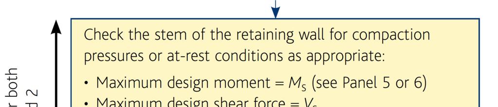
 9 Panel 2")
52 Calcs Material properties & earth pressures 9 (Panel 2) 9 Panel 2 (p71) 2
53 Overall design procedure 9 (Figure 4)
 Design")

")
54 9 (Figure 7) Design against sliding (Figure 7)
55 Sliding Resistance 9 (Panel 3)
56 Overall design procedure 9 (Figure 4)

57 Design against Toppling 9 (Figure 9)
58 Overall design procedure 9 (Figure 4)

59 Design against bearing failure 9 (Figure 10)

60 Expressions for bearing resistance 9 (Panel 4,Figure 11)

61 Overall design procedure 9 (Figure 4)
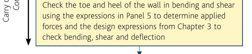
62 Structural design 9 (Figure 13)
63 Remember: Load and Partial Factor Combinations Parameter Symbol Comb. 1 Comb. 2 Actions Permanent action : unfavourable γ G,unfav Permanent action: favourable γ G,fav Variable action γ Q Soil Properties Angle of shearing resistance γ φ Effective cohesion γ c Undrained shear strength γ cu Unconfined strength γ qu Bulk density γ γ
64 Piles
65 Flexural and axial resistance of piles Uncertainties related to the cross-section of cast in place piles and concreting procedures shall be allowed for in design In the absence of other provisions, the design diameter of cast in place piles without permanent casing is less than the nominal diameter D nom : D d = D nom 20 mm for D nom < 400 mm D d = 0.95 D nom for 400 D nom 1000 mm D d = D nom 50 mm for D nom > 1000 mm ICE Specification for piling and embedded retaining walls (ICE SPERW) B states The dimensions of a constructed pile or wall element shall not be less than the specified dimensions. A tolerance of 5% on auger diameter, casing diameter, and grab length and width is permissible.
66 Flexural and axial resistance of piles The partial factor for concrete, γ c, should be multiplied by a factor, k f, for calculation of design resistance of cast in place piles without permanent casing. The UK value of k f = 1.1, therefore γ c,pile = 1.65 If the width of the compression zone decreases in the direction of the extreme compression fibre, the value η f cd should be reduced by 10%
67 Bored piles Reinforcement should be detailed for free flow of concrete. Minimum diameter of long. reinforcement = 16mm Minimum number of longitudinal bars = 6 [BUT BS EN 1536 Execution of special geotechnical work Bored Piles says 12 mm and 4 bars!] Minimum areas: Pile cross Min area of long. Pile section: A c rebar, A s,bpmin diameters A c 0.5 m 2 0.5% A c < 800 mm 0.5 m 2 < A c 1.0 m mm 2 A c > 1.0 m % A c >1130 mm
68 Minimum reinforcement Minimum area of reinforcement, A s,bpmin (mm 2 ) Pile diameter, mm
69 Workshop Design a pad foundation for a 300mm square column taking G k = 600kN, Q k = 350kN. Permissible bearing stress = 225kPa. Concrete for base C30/37. Work out size of base, tension reinforcement and any shear reinforcement.
70 Workshop Problem Category 2, using prescriptive methods Base size: (G k + Q k )/bearing stress = = _m 2 x base x mm deep (choose size of pad) Use C 30/37 (concrete) Loading = γ g x G k + γ q x Q k = = kn ULS bearing pressure = / 2 = kn/m 2 Critical section at face of column M Ed = x x 2 / 2 = knm d = cover assumed ø = = mm K = M/bd 2 f ck =
71 Workshop Problem z = d = x = mm Table 15.5 A s = M Ed /f yd z = mm 2 Provide c/c ( mm 2 ) Check minimum steel 100A s,prov /bd = For C30/37 concrete A s,min = OK/not OK Beam shear Check critical section d away from column face V Ed = x = kn/m v Ed = V Ed / d = MPa ρ = / ( x ) = = % v Rd,c (from table) = MPa beam shear OK/not OK
72 Workshop Problem Punching shear Basic control perimeter at 2d from face of column v Ed = βv Ed / u i d < v Rd,c β = 1, u i = = mm V Ed = load minus net upward force within the area of the control perimeter) = x ( ) = kn v Ed = MPa; v Rd,c = (as before) => ok/not ok
73 End of Lecture 10 (and the course!) s:
74 Model answer: Workshop Problem Category 2, using prescriptive methods Base size: ( )/225 = 4.22m x 2.1 base x 450mm (say) deep Use C30/37 Loading = 1.35 x x 350 = 1335kN ULS bearing pressure = 1335/2.1 2 = 303kN/m 2 Critical section at face of column M Ed = 303 x 2.1 x ( ) 2 / 2 = 258kNm d = = 384mm K = 258 x 10 6 / (2100 x x 30) = 0.028
75 Model answer: Workshop Problem z = 0.95d = 0.95 x 384 = 365mm A s = M Ed /f yd z = 258 x 10 6 / (435 x 365) = 1626mm 2 Provide 250 c/c (1688mm 2 ) (804 mm2/m) Check minimum steel 100A s,prov /bd = 100 x 1688 / 2100 / 384 = For C30/37 concrete A s,min = OK Beam shear Check critical section d away from column face V Ed = 303 x ( ) = 156kN/m v Ed = 156 / 384 = 0.41MPa v Rd,c (from table) = 0.44MPa => beam shear ok.
76 Model answer: Workshop Problem Punching shear Basic control perimeter at 2d from face of column v Ed = βv Ed / u i d < v Rd,c β = 1, u i = (300 x x 2 x 2 x π) = 6025mm V Ed = load minus net upward force within the area of the control perimeter) = x ( π x x.3 x 4) = 467kN v Ed = 467 x 10 3 /(6025 x 384) = 0.202MPa; v Rd,c = 0.44 (as before) => ok
O Dr Andrew Bond (Geocentrix)
") DECODING EUROCODES 2 + 7: DESIGN SG OF FOUNDATIONS O Dr Andrew Bond (Geocentrix) Outline of talk April 2010: the death of British Standards? UK implementation of Eurocodes Verification of strength: limit
DECODING EUROCODES 2 + 7: DESIGN SG OF FOUNDATIONS O Dr Andrew Bond (Geocentrix) Outline of talk April 2010: the death of British Standards? UK implementation of Eurocodes Verification of strength: limit
Bending and Shear in Beams
 Bending and Shear in Beams Lecture 3 5 th October 017 Contents Lecture 3 What reinforcement is needed to resist M Ed? Bending/ Flexure Section analysis, singly and doubly reinforced Tension reinforcement,
Detailing. Lecture 9 16 th November Reinforced Concrete Detailing to Eurocode 2
 Detailing Lecture 9 16 th November 2017 Reinforced Concrete Detailing to Eurocode 2 EC2 Section 8 - Detailing of Reinforcement - General Rules Bar spacing, Minimum bend diameter Anchorage of reinforcement
Practical Design to Eurocode 2
 Practical Design to Eurocode 2 The webinar will start at 12.30 (Any questions beforehand? use Questions on the GoTo Control Panel) Course Outline Lecture Date Speaker Title 1 21 Sep Jenny Burridge Introduction,
EN Eurocode 7. Section 3 Geotechnical Data Section 6 Spread Foundations. Trevor L.L. Orr Trinity College Dublin Ireland.
 EN 1997 1: Sections 3 and 6 Your logo Brussels, 18-20 February 2008 Dissemination of information workshop 1 EN 1997-1 Eurocode 7 Section 3 Geotechnical Data Section 6 Spread Foundations Trevor L.L. Orr
Tower Cranes & Foundations The Interface & CIRIA C654 Stuart Marchand C.Eng. FICE FIStructE Director Wentworth House Partnership
 Tower Cranes & Foundations The Interface & CIRIA C654 Stuart Marchand C.Eng. FICE FIStructE Director Wentworth House Partnership EXAMPLES OF TOWER CRANE FOUNDATION TYPES Rail mounted Pad Base Piled Base
Concise Eurocode 2 25 February 2010
 Concise Eurocode 2 25 February 2010 Revisions required to Concise Eurocode 2 (Oct 06 edition) due to revisions in standards, notably Amendment 1 to NA to BS EN 1992-1-1:2004 dated Dec 2009, and interpretations.
DESIGN OF STAIRCASE. Dr. Izni Syahrizal bin Ibrahim. Faculty of Civil Engineering Universiti Teknologi Malaysia
 DESIGN OF STAIRCASE Dr. Izni Syahrizal bin Ibrahim Faculty of Civil Engineering Universiti Teknologi Malaysia Email: iznisyahrizal@utm.my Introduction T N T G N G R h Flight Span, L Landing T = Thread
Design of AAC wall panel according to EN 12602
 Design of wall panel according to EN 160 Example 3: Wall panel with wind load 1.1 Issue Design of a wall panel at an industrial building Materials with a compressive strength 3,5, density class 500, welded
Practical Design to Eurocode 2
 Practical Design to Eurocode 2 The webinar will start at 12.30 (I m happy to field individual questions beforehand Use Questions on the shown Control Panel) Course Outline Lecture Date Speaker Title 1
Seminar Worked examples on Bridge Design with Eurocodes
 1 EU-Russia Regulatory Dialogue: Construction Sector Subgroup Seminar Worked examples on Bridge Design with Eurocodes St-Petersburg, 17-18 April 2013 Organized and supported by European Commission DG Joint
Introduction to The Design Example and EN Basis of Design
 EUROCODES Bridges: Background and applications St Petersburg April 2011 1 Introduction to The Design Example and EN 1990 - Basis of Design Professor Steve Denton Engineering Director, Parsons Brinckerhoff
Annex - R C Design Formulae and Data
 The design formulae and data provided in this Annex are for education, training and assessment purposes only. They are based on the Hong Kong Code of Practice for Structural Use of Concrete 2013 (HKCP-2013).
- Rectangular Beam Design -
 Semester 1 2016/2017 - Rectangular Beam Design - Department of Structures and Material Engineering Faculty of Civil and Environmental Engineering University Tun Hussein Onn Malaysia Introduction The purposes
Practical Design to Eurocode 2
 Practical Design to Eurocode 2 The webinar will start at 12.30 Course Outline Lecture Date Speaker Title 1 21 Sep Jenny Burridge Introduction, Background and Codes 2 28 Sep Charles Goodchild EC2 Background,
Assignment 1 - actions
 Assignment 1 - actions b = 1,5 m a = 1 q kn/m 2 Determine action on the beam for verification of the ultimate limit state. Axial distance of the beams is 1 to 2 m, cross section dimensions 0,45 0,20 m
Erratum. Chapter 4 - Earth and water pressure 26. Chapter Area loads. q a. c+d ϕ'/2. Piling Handbook, 9th edition (2016)
") Chapter 4 - Earth and water pressure 26 Chapter 4.9.15. Area loads z x q ϕ' a c+d 45 + ϕ'/2 Fig. 4.3. Force distribution area lords. Chapter 5 - Design of steel sheetpile structures 22 Chapter 5.8.3. Surcharge
Chapter 4 - Earth and water pressure 26 Chapter 4.9.15. Area loads z x q ϕ' a c+d 45 + ϕ'/2 Fig. 4.3. Force distribution area lords. Chapter 5 - Design of steel sheetpile structures 22 Chapter 5.8.3. Surcharge
Civil Engineering Design (1) Design of Reinforced Concrete Columns 2006/7
 Design of Reinforced Concrete Columns 2006/7") Civil Engineering Design (1) Design of Reinforced Concrete Columns 2006/7 Dr. Colin Caprani, Chartered Engineer 1 Contents 1. Introduction... 3 1.1 Background... 3 1.2 Failure Modes... 5 1.3 Design Aspects...
Civil Engineering Design (1) Design of Reinforced Concrete Columns 2006/7 Dr. Colin Caprani, Chartered Engineer 1 Contents 1. Introduction... 3 1.1 Background... 3 1.2 Failure Modes... 5 1.3 Design Aspects...
DESIGN AND DETAILING OF COUNTERFORT RETAINING WALL
 DESIGN AND DETAILING OF COUNTERFORT RETAINING WALL When the height of the retaining wall exceeds about 6 m, the thickness of the stem and heel slab works out to be sufficiently large and the design becomes
Serviceability Limit States
 Serviceability Limit States www.eurocode2.info 1 Outline Crack control and limitations Crack width calculations Crack width calculation example Crack width calculation problem Restraint cracking Deflection
Worked examples. Dr. Bernd Schuppener German Federal Waterways Engineering and Research Institute, Karlsruhe Past Chairman of CEN TC250/SC 7
 13-14 June 2013, Dublin Worked examples HYD and UPL limit it states Dr. Bernd Schuppener German Federal Waterways Engineering and Research Institute, Karlsruhe Past Chairman of CEN TC250/SC 7 Worked example:
SERVICEABILITY LIMIT STATE DESIGN
 CHAPTER 11 SERVICEABILITY LIMIT STATE DESIGN Article 49. Cracking Limit State 49.1 General considerations In the case of verifications relating to Cracking Limit State, the effects of actions comprise
CE5510 Advanced Structural Concrete Design - Design & Detailing of Openings in RC Flexural Members-
 CE5510 Advanced Structural Concrete Design - Design & Detailing Openings in RC Flexural Members- Assoc Pr Tan Kiang Hwee Department Civil Engineering National In this lecture DEPARTMENT OF CIVIL ENGINEERING
Job No. Sheet No. Rev. CONSULTING Engineering Calculation Sheet. Member Design - RC Two Way Spanning Slab XX
 CONSULTING Engineering Calculation Sheet E N G I N E E R S Consulting Engineers jxxx 1 Material Properties Characteristic strength of concrete, f cu ( 60N/mm 2 ; HSC N/A) 35 N/mm 2 OK Yield strength of
Job No. Sheet No. Rev. CONSULTING Engineering Calculation Sheet
 E N G I N E E R S Consulting Engineers jxxx 1 Material Properties Characteristic strength of concrete, f cu ( 60N/mm 2 ; HSC N/A) 35 N/mm 2 OK Yield strength of longitudinal steel, f y 460 N/mm 2 Yield
Delhi Noida Bhopal Hyderabad Jaipur Lucknow Indore Pune Bhubaneswar Kolkata Patna Web: Ph:
 Serial : IG1_CE_G_Concrete Structures_100818 Delhi Noida Bhopal Hyderabad Jaipur Lucknow Indore Pune Bhubaneswar Kolkata Patna Web: E-mail: info@madeeasy.in Ph: 011-451461 CLASS TEST 018-19 CIVIL ENGINEERING
NAGY GYÖRGY Tamás Assoc. Prof, PhD
 NAGY GYÖRGY Tamás Assoc. Prof, PhD E mail: tamas.nagy gyorgy@upt.ro Tel: +40 256 403 935 Web: http://www.ct.upt.ro/users/tamasnagygyorgy/index.htm Office: A219 SIMPLE SUPORTED BEAM b = 15 cm h = 30 cm
The Concepts of Eurocode 7 for Harmonised Geotechnical Design in Europe
 1 The Concepts of Eurocode 7 for Harmonised Geotechnical Design in Europe by Trevor Orr Trinity College Dublin at Politechnika Wrocławska Studia Doktoranckie on 8 th to 12 th February 2010 2 Day 2 Development
Associate Professor. Tel:
 DEPARTMENT OF CIVIL ENGINEERING IIT DELHI Dr. Suresh Bhalla Associate Professor Tel: 2659-1040 Email: Sbhalla@civil.iitd.ac.in FOUNDATIONS Geotechnical Engineer Structural Engineer Location and depth criteria
GEOTECHNICAL ENGINEERING ECG 503 LECTURE NOTE ANALYSIS AND DESIGN OF RETAINING STRUCTURES
 GEOTECHNICAL ENGINEERING ECG 503 LECTURE NOTE 07 3.0 ANALYSIS AND DESIGN OF RETAINING STRUCTURES LEARNING OUTCOMES Learning outcomes: At the end of this lecture/week the students would be able to: Understand
Design of reinforced concrete sections according to EN and EN
 Design of reinforced concrete sections according to EN 1992-1-1 and EN 1992-2 Validation Examples Brno, 21.10.2010 IDEA RS s.r.o. South Moravian Innovation Centre, U Vodarny 2a, 616 00 BRNO tel.: +420-511
Department of Mechanics, Materials and Structures English courses Reinforced Concrete Structures Code: BMEEPSTK601. Lecture no. 6: SHEAR AND TORSION
 Budapest University of Technology and Economics Department of Mechanics, Materials and Structures English courses Reinforced Concrete Structures Code: BMEEPSTK601 Lecture no. 6: SHEAR AND TORSION Reinforced
Eurocode Training EN : Reinforced Concrete
 Eurocode Training EN 1992-1-1: Reinforced Concrete Eurocode Training EN 1992-1-1 All information in this document is subject to modification without prior notice. No part of this manual may be reproduced,
RETAINING WALL ANALYSIS
 GEODOMISI Ltd. Dr. Costas Sachpazis Consulting Company for Tel.: (+30) 20 523827, 20 57263 Fax.:+30 20 5746 Retaining wall Analysis & Design (EN997:2004 App'd by RETAINING WALL ANALYSIS In accordance with
RETAINING WALL ANALYSIS
 Retaining Wall Analysis Example (EN997:2004) GEODOMISI Ltd. Dr. Costas Sachpazis Consulting Company for Tel.: (+30) 20 523827, 20 57263 Fax.:+30 20 5746 App'd by RETAINING WALL ANALYSIS In accordance with
Session 3. Calculation Models. EQU, UPL and HYD. Design of Pile Foundations
 1 Session 3 Calculation Models EQU, UPL and HYD Design of Pile Foundations (Killiney Bay) 2 SLS and Settlement Calculations (Dalkey Island) Summary of ULS Designs Undrained width (m) Drained width (m)
EUROCODE EN SEISMIC DESIGN OF BRIDGES
 Brussels, 18-20 February 2008 Dissemination of information workshop 1 EUROCODE EN1998-2 SEISMIC DESIGN OF BRIDGES Basil Kolias Basic Requirements Brussels, 18-20 February 2008 Dissemination of information
Job No. Sheet No. Rev. CONSULTING Engineering Calculation Sheet. Member Design - Reinforced Concrete Staircase BS8110
 CONSULTING Engineering Calculation Sheet E N G I N E E R S Consulting Engineers jxxx 1 Material Properties Characteristic strength of concrete, f cu ( 60N/mm 2 ; HSC N/A) 25 N/mm 2 OK Yield strength of
CHAPTER 4. Design of R C Beams
 CHAPTER 4 Design of R C Beams Learning Objectives Identify the data, formulae and procedures for design of R C beams Design simply-supported and continuous R C beams by integrating the following processes
Job No. Sheet No. Rev. CONSULTING Engineering Calculation Sheet. Member Design - Reinforced Concrete Beam BS8110 v Member Design - RC Beam XX
 CONSULTING Engineering Calculation Sheet E N G I N E E R S Consulting Engineers jxxx 1 Effects From Structural Analysis Design axial force, F (tension -ve and compression +ve) (ensure < 0.1f cu b w h 0
Session 4. Risk and Reliability. Design of Retaining Structures. Slopes, Overall Stability and Embankments. (Blarney Castle)
") Session 4 Risk and Reliability Design of Retaining Structures Slopes, Overall Stability and Embankments (Blarney Castle) 1 2 Session 4a Risk and reliability Complexity and Geotechnical Risk The complexity
Session 4 Risk and Reliability Design of Retaining Structures Slopes, Overall Stability and Embankments (Blarney Castle) 1 2 Session 4a Risk and reliability Complexity and Geotechnical Risk The complexity
Standardisation of UHPC in Germany
 Standardisation of UHPC in Germany Part II: Development of Design Rules, University of Siegen Prof. Dr.-Ing. Ekkehard Fehling, University of Kassel 1 Overvie Introduction: Work of the Task Group Design
Job No. Sheet No. Rev. CONSULTING Engineering Calculation Sheet. Member Design - Reinforced Concrete Staircase BS8110
 CONSULTING Engineering Calculation Sheet E N G I N E E R S Consulting Engineers jxxx 1 Material Properties Characteristic strength of concrete, f cu ( 60N/mm 2 ; HSC N/A) 30 N/mm 2 OK Yield strength of
UNIT II SHALLOW FOUNDATION
 Introduction UNIT II SHALLOW FOUNDATION A foundation is a integral part of the structure which transfer the load of the superstructure to the soil. A foundation is that member which provides support for
Design of a Multi-Storied RC Building
 Design of a Multi-Storied RC Building 16 14 14 3 C 1 B 1 C 2 B 2 C 3 B 3 C 4 13 B 15 (S 1 ) B 16 (S 2 ) B 17 (S 3 ) B 18 7 B 4 B 5 B 6 B 7 C 5 C 6 C 7 C 8 C 9 7 B 20 B 22 14 B 19 (S 4 ) C 10 C 11 B 23
Reinforced concrete structures II. 4.5 Column Design
 4.5 Column Design A non-sway column AB of 300*450 cross-section resists at ultimate limit state, an axial load of 700 KN and end moment of 90 KNM and 0 KNM in the X direction,60 KNM and 27 KNM in the Y
Flexure: Behavior and Nominal Strength of Beam Sections
 4 5000 4000 (increased d ) (increased f (increased A s or f y ) c or b) Flexure: Behavior and Nominal Strength of Beam Sections Moment (kip-in.) 3000 2000 1000 0 0 (basic) (A s 0.5A s ) 0.0005 0.001 0.0015
Design of Reinforced Concrete Beam for Shear
 Lecture 06 Design of Reinforced Concrete Beam for Shear By: Prof Dr. Qaisar Ali Civil Engineering Department UET Peshawar drqaisarali@uetpeshawar.edu.pk 1 Topics Addressed Shear Stresses in Rectangular
STRUCTURAL ANALYSIS CHAPTER 2. Introduction
 CHAPTER 2 STRUCTURAL ANALYSIS Introduction The primary purpose of structural analysis is to establish the distribution of internal forces and moments over the whole part of a structure and to identify
CRACK FORMATION AND CRACK PROPAGATION INTO THE COMPRESSION ZONE ON REINFORCED CONCRETE BEAM STRUCTURES
 S. Kakay et al. Int. J. Comp. Meth. and Exp. Meas. Vol. 5 No. (017) 116 14 CRACK FORMATION AND CRACK PROPAGATION INTO THE COMPRESSION ZONE ON REINFORCED CONCRETE BEAM STRUCTURES SAMDAR KAKAY DANIEL BÅRDSEN
RELIABILITY ASSESSMENT OF EXISTING STRUCTURES
 1. Introduction RELIABILITY ASSESSMENT OF EXISTING STRUCTURES EN Eurocodes, presently being implemented into the system of national standards nearly in the whole Europe, are particularly intended for the
Design of Reinforced Concrete Beam for Shear
 Lecture 06 Design of Reinforced Concrete Beam for Shear By: Civil Engineering Department UET Peshawar drqaisarali@uetpeshawar.edu.pk Topics Addressed Shear Stresses in Rectangular Beams Diagonal Tension
Bored piles in clay and Codes of Practice. Malcolm Bolton
 Bored piles in clay and Codes of Practice Malcolm Bolton Background: design and decision-making Why is design not yet evidence-based? Reliance on past practice, rather than validation. Safety factors have
1. ARRANGEMENT. a. Frame A1-P3. L 1 = 20 m H = 5.23 m L 2 = 20 m H 1 = 8.29 m L 3 = 20 m H 2 = 8.29 m H 3 = 8.39 m. b. Frame P3-P6
 Page 3 Page 4 Substructure Design. ARRANGEMENT a. Frame A-P3 L = 20 m H = 5.23 m L 2 = 20 m H = 8.29 m L 3 = 20 m H 2 = 8.29 m H 3 = 8.39 m b. Frame P3-P6 L = 25 m H 3 = 8.39 m L 2 = 3 m H 4 = 8.5 m L
Job No. Sheet No. Rev. CONSULTING Engineering Calculation Sheet
 CONSULTING Engineering Calculation Sheet jxxx 1 Effects From Structural Analysis Design axial force, F (tension -ve and compression +ve) (ensure < 0.1f cu b w h 0 kn OK Design shear force, V d 4223 kn
Design of a Balanced-Cantilever Bridge
 Design of a Balanced-Cantilever Bridge CL (Bridge is symmetric about CL) 0.8 L 0.2 L 0.6 L 0.2 L 0.8 L L = 80 ft Bridge Span = 2.6 L = 2.6 80 = 208 Bridge Width = 30 No. of girders = 6, Width of each girder
five Mechanics of Materials 1 ARCHITECTURAL STRUCTURES: FORM, BEHAVIOR, AND DESIGN DR. ANNE NICHOLS SUMMER 2017 lecture
 ARCHITECTURAL STRUCTURES: FORM, BEHAVIOR, AND DESIGN DR. ANNE NICHOLS SUMMER 2017 lecture five mechanics www.carttalk.com of materials Mechanics of Materials 1 Mechanics of Materials MECHANICS MATERIALS
Job No. Sheet No. Rev. CONSULTING Engineering Calculation Sheet
 CONSULTING Engineering Calculation Sheet E N G I N E E R S Consulting Engineers jxxx 1 Effects From Structural Analysis Design axial force, F (tension -ve and compression +ve) (ensure < 0.1f cu b w h 0
Reliability analysis of geotechnical risks
 Reliability analysis of geotechnical risks Lazhar Belabed*, Hacene Benyaghla* * Department of Civil Engineering and Hydraulics, University of Guelma, Algeria Abstract The evaluation of safety or reliability
3-BEARING CAPACITY OF SOILS
 3-BEARING CAPACITY OF SOILS INTRODUCTION The soil must be capable of carrying the loads from any engineered structure placed upon it without a shear failure and with the resulting settlements being tolerable
REINFORCED CONCRETE DESIGN 1. Design of Column (Examples and Tutorials)
") For updated version, please click on http://ocw.ump.edu.my REINFORCED CONCRETE DESIGN 1 Design of Column (Examples and Tutorials) by Dr. Sharifah Maszura Syed Mohsin Faculty of Civil Engineering and Earth
For updated version, please click on http://ocw.ump.edu.my REINFORCED CONCRETE DESIGN 1 Design of Column (Examples and Tutorials) by Dr. Sharifah Maszura Syed Mohsin Faculty of Civil Engineering and Earth
Concrete and Masonry Structures 1 Office hours
 Concrete and Masonry Structures 1 Petr Bílý, office B731 http://people.fsv.cvut.cz/www/bilypet1 Courses in English Concrete and Masonry Structures 1 Office hours Credit receiving requirements General knowledge
Entrance exam Master Course
 - 1 - Guidelines for completion of test: On each page, fill in your name and your application code Each question has four answers while only one answer is correct. o Marked correct answer means 4 points
EUROCODES. Background and Applications. EN 1997 Eurocode 7: Geotechnical design. Dissemination of information for training workshop
 Dissemination of information for training workshop 18-20 February 2008 Brussels EN 1997 Eurocode 7: Geotechnical design Organised by European Commission: DG Enterprise and Industry, Joint Research Centre
3.2 Reinforced Concrete Slabs Slabs are divided into suspended slabs. Suspended slabs may be divided into two groups:
 Sabah Shawkat Cabinet of Structural Engineering 017 3. Reinforced Concrete Slabs Slabs are divided into suspended slabs. Suspended slabs may be divided into two groups: (1) slabs supported on edges of
Seismic design of bridges
 NATIONAL TECHNICAL UNIVERSITY OF ATHENS LABORATORY FOR EARTHQUAKE ENGINEERING Seismic design of bridges Lecture 3 Ioannis N. Psycharis Capacity design Purpose To design structures of ductile behaviour
Case Study in Reinforced Concrete adapted from Simplified Design of Concrete Structures, James Ambrose, 7 th ed.
 ARCH 631 Note Set 11 S017abn Case Study in Reinforced Concrete adapted from Simplified Design of Concrete Structures, James Ambrose, 7 th ed. Building description The building is a three-story office building
HKIE-GD Workshop on Foundation Engineering 7 May Shallow Foundations. Dr Limin Zhang Hong Kong University of Science and Technology
 HKIE-GD Workshop on Foundation Engineering 7 May 2011 Shallow Foundations Dr Limin Zhang Hong Kong University of Science and Technology 1 Outline Summary of design requirements Load eccentricity Bearing
Einführung des EC2 in Belgien The introduction of EC2 in Belgium
 Luc Taerwe 1 Einführung des EC2 in Belgien The introduction of EC2 in Belgium Luc Taerwe Univ.-Prof. Dr.-Ing. habil. Luc Taerwe - graduated as civil engineer at Ghent University (1975) where he also obtained
Clayey sand (SC)
") Pile Bearing Capacity Analysis / Verification Input data Project Task : PROJECT: "NEW STEAM BOILER U-5190 Part : A-1 Descript. : The objective of this Analysis is the Pile allowable bearing Capacity Analysis
Pile Bearing Capacity Analysis / Verification Input data Project Task : PROJECT: "NEW STEAM BOILER U-5190 Part : A-1 Descript. : The objective of this Analysis is the Pile allowable bearing Capacity Analysis
Introduction to Soil Mechanics
 Introduction to Soil Mechanics Sela Sode and Colin Jones WILEY Blackwell Contents Preface Dedication and Acknowledgments List of Symbols Soil Structure 1.1 Volume relationships 1.1.1 Voids ratio (e) 1.1.2
Design Example 2.2. Pad foundation with inclined eccentric load on boulder clay
 Design Example 2.2. Pad foundation with inclined eccentric load on boulder clay 1. Obtaining characteristic value of undrained shear strength Due to conditions given in the example a decision was made
Foundation Engineering Prof. Dr. N. K. Samadhiya Department of Civil Engineering Indian Institute of Technology Roorkee
 Foundation Engineering Prof. Dr. N. K. Samadhiya Department of Civil Engineering Indian Institute of Technology Roorkee Module - 01 Lecture - 01 Shallow Foundation (Refer Slide Time: 00:19) Good morning.
Analysis of the horizontal bearing capacity of a single pile
 Engineering manual No. 16 Updated: 07/2018 Analysis of the horizontal bearing capacity of a single pile Program: Soubor: Pile Demo_manual_16.gpi The objective of this engineering manual is to explain how
INTRODUCTION TO STATIC ANALYSIS PDPI 2013
 INTRODUCTION TO STATIC ANALYSIS PDPI 2013 What is Pile Capacity? When we load a pile until IT Fails what is IT Strength Considerations Two Failure Modes 1. Pile structural failure controlled by allowable
The Bearing Capacity of Soils. Dr Omar Al Hattamleh
 The Bearing Capacity of Soils Dr Omar Al Hattamleh Example of Bearing Capacity Failure Omar Play the move of bearing Capacity failure The Philippine one Transcona Grain Silos Failure - Canada The Bearing
Structural Steelwork Eurocodes Development of A Trans-national Approach
 Structural Steelwork Eurocodes Development of A Trans-national Approach Course: Eurocode Module 7 : Worked Examples Lecture 0 : Simple braced frame Contents: 1. Simple Braced Frame 1.1 Characteristic Loads
Foundation Engineering Prof. Dr N.K. Samadhiya Department of Civil Engineering Indian Institute of Technology Roorkee
 Foundation Engineering Prof. Dr N.K. Samadhiya Department of Civil Engineering Indian Institute of Technology Roorkee Module 01 Lecture - 03 Shallow Foundation So, in the last lecture, we discussed the
10/14/2011. Types of Shear Failure. CASE 1: a v /d 6. a v. CASE 2: 2 a v /d 6. CASE 3: a v /d 2
 V V Types o Shear Failure a v CASE 1: a v /d 6 d V a v CASE 2: 2 a v /d 6 d V a v CASE 3: a v /d 2 d V 1 Shear Resistance Concrete compression d V cz = Shear orce in the compression zone (20 40%) V a =
CONSULTING Engineering Calculation Sheet. Job Title Member Design - Reinforced Concrete Column BS8110
 E N G I N E E R S Consulting Engineers jxxx 1 Job Title Member Design - Reinforced Concrete Column Effects From Structural Analysis Axial force, N (tension-ve and comp +ve) (ensure >= 0) 8000kN OK Major
Lecture-04 Design of RC Members for Shear and Torsion
 Lecture-04 Design of RC Members for Shear and Torsion By: Prof. Dr. Qaisar Ali Civil Engineering Department UET Peshawar drqaisarali@uetpeshawar.edu.pk www.drqaisarali.com 1 Topics Addressed Design of
DEFORMATION CAPACITY OF OLDER RC SHEAR WALLS: EXPERIMENTAL ASSESSMENT AND COMPARISON WITH EUROCODE 8 - PART 3 PROVISIONS
 DEFORMATION CAPACITY OF OLDER RC SHEAR WALLS: EXPERIMENTAL ASSESSMENT AND COMPARISON WITH EUROCODE 8 - PART 3 PROVISIONS Konstantinos CHRISTIDIS 1, Emmanouil VOUGIOUKAS 2 and Konstantinos TREZOS 3 ABSTRACT
Reinforced Soil Structures Reinforced Soil Walls. Prof K. Rajagopal Department of Civil Engineering IIT Madras, Chennai
 Geosynthetics and Reinforced Soil Structures Reinforced Soil Walls continued Prof K. Rajagopal Department of Civil Engineering IIT Madras, Chennai e-mail: gopalkr@iitm.ac.inac in Outline of the Lecture
Figure 1: Representative strip. = = 3.70 m. min. per unit length of the selected strip: Own weight of slab = = 0.
 Example (8.1): Using the ACI Code approximate structural analysis, design for a warehouse, a continuous one-way solid slab supported on beams 4.0 m apart as shown in Figure 1. Assume that the beam webs
TABLE OF CONTANINET 1. Design criteria. 2. Lateral loads. 3. 3D finite element model (SAP2000, Ver.16). 4. Design of vertical elements (CSI, Ver.9).
. 4. Design of vertical elements (CSI, Ver.9).") TABLE OF CONTANINET 1. Design criteria. 2. Lateral loads. 2-1. Wind loads calculation 2-2. Seismic loads 3. 3D finite element model (SAP2000, Ver.16). 4. Design of vertical elements (CSI, Ver.9). 4-1.
TABLE OF CONTANINET 1. Design criteria. 2. Lateral loads. 2-1. Wind loads calculation 2-2. Seismic loads 3. 3D finite element model (SAP2000, Ver.16). 4. Design of vertical elements (CSI, Ver.9). 4-1.
Seismic Design, Assessment & Retrofitting of Concrete Buildings. fctm. h w, 24d bw, 175mm 8d bl, 4. w 4 (4) 2 cl
 2 cl") Seismic Design, Assessment & Retroitting o Concrete Buildings Table 5.1: EC8 rules or detailing and dimensioning o primary beams (secondary beams: as in DCL) DC H DCM DCL critical region length 1.5h w
Seismic Design, Assessment & Retroitting o Concrete Buildings Table 5.1: EC8 rules or detailing and dimensioning o primary beams (secondary beams: as in DCL) DC H DCM DCL critical region length 1.5h w
Engineeringmanuals. Part2
 Engineeringmanuals Part2 Engineering manuals for GEO5 programs Part 2 Chapter 1-12, refer to Engineering Manual Part 1 Chapter 13. Pile Foundations Introduction... 2 Chapter 14. Analysis of vertical load-bearing
Reliability-based ultimate limit state design in finite element methods
 Delft University of Technology Faculty of Civil Engineering and Geosciences Section Geo-Engineering, Civil Engineering Reliability-based ultimate limit state design in finite element methods Author: Stefan
CHAPTER 8 CALCULATION THEORY
 CHAPTER 8 CALCULATION THEORY. Volume 2 CHAPTER 8 CALCULATION THEORY Detailed in this chapter: the theories behind the program the equations and methods that are use to perform the analyses. CONTENTS CHAPTER
Improving fire resistance of existing concrete slabs by concrete topping
 Improving fire resistance of existing concrete slabs by concrete topping Is EN 1992-1-2 annex E telling the truth, and can it be used? Tom Molkens StuBeCo bvba, Overpelt - Belgium Structures in Fire Forum
Visit Abqconsultants.com. This program Designs and Optimises RCC Chimney and Foundation. Written and programmed
 Prepared by : Date : Verified by : Date : Project : Ref Calculation Output Design of RCC Chimney :- 1) Dimensions of Chimney and Forces 200 Unit weight of Fire Brick Lining 19000 N/m3 100 Height of Fire
Strengthening of columns with FRP
 with FRP Professor Dr. Björn Täljsten Luleå University of Technology Sto Scandinavia AB 9/12/2013 Agenda Case study Restrained transverse expansion (confinement) Circular and rectangular cross sections
Composite bridge design (EN1994-2) Bridge modelling and structural analysis
 Bridge modelling and structural analysis") EUROCODES Bridges: Background and applications Dissemination of information for training Vienna, 4-6 October 2010 1 Composite bridge design (EN1994-2) Bridge modelling and structural analysis Laurence
EUROCODES Bridges: Background and applications Dissemination of information for training Vienna, 4-6 October 2010 1 Composite bridge design (EN1994-2) Bridge modelling and structural analysis Laurence
Chapter (3) Ultimate Bearing Capacity of Shallow Foundations
 Ultimate Bearing Capacity of Shallow Foundations") Chapter (3) Ultimate Bearing Capacity of Shallow Foundations Introduction To perform satisfactorily, shallow foundations must have two main characteristics: 1. They have to be safe against overall shear
Chapter (3) Ultimate Bearing Capacity of Shallow Foundations Introduction To perform satisfactorily, shallow foundations must have two main characteristics: 1. They have to be safe against overall shear
EXAMPLE CALCULATIONS DTF / DTS
 MEMO 830 DTF / DTS EXAMPLE CALCULATIONS DESIGN Dato: Siste rev.: Dok. nr.: 19.09.013 5.05.016 K4-10/30E Sign.: Sign.: Control: sss ps CONTENT EXAMPLE CALCULATIONS DTF / DTS EXAMPLE CALCULATIONS DTF / DTS...
Safety Concepts and Calibration of Partial Factors in European and North American Codes of Practice
 Safety Concepts and Calibration of Partial Factors in European and North American Codes of Practice The Dutch approach on Geotechnical Design by Eurocode 7 Adriaan van Seters Hein Jansen Fugro GeoServices
Chapter 8. Shear and Diagonal Tension
 Chapter 8. and Diagonal Tension 8.1. READING ASSIGNMENT Text Chapter 4; Sections 4.1-4.5 Code Chapter 11; Sections 11.1.1, 11.3, 11.5.1, 11.5.3, 11.5.4, 11.5.5.1, and 11.5.6 8.2. INTRODUCTION OF SHEAR
vulcanhammer.net This document downloaded from
 This document downloaded from vulcanhammer.net since 1997, your source for engineering information for the deep foundation and marine construction industries, and the historical site for Vulcan Iron Works
Example 2.2 [Ribbed slab design]
![Example 2.2 [Ribbed slab design]](/thumbs/78/77625473.jpg "Example 2.2 [Ribbed slab design]") Example 2.2 [Ribbed slab design] A typical floor system of a lecture hall is to be designed as a ribbed slab. The joists which are spaced at 400mm are supported by girders. The overall depth of the slab
Example 2.2 [Ribbed slab design] A typical floor system of a lecture hall is to be designed as a ribbed slab. The joists which are spaced at 400mm are supported by girders. The overall depth of the slab
Example 4.1 [Uni-axial Column Design] Solution. Step 1- Material Step 2-Determine the normalized axial and bending moment value
![Example 4.1 [Uni-axial Column Design] Solution. Step 1- Material Step 2-Determine the normalized axial and bending moment value](/thumbs/75/72436916.jpg "Example 4.1 [Uni-axial Column Design] Solution. Step 1- Material Step 2-Determine the normalized axial and bending moment value") Example 4.1 [Uni-axial Column Design] 1. Design the braced short column to sustain a design load of 1100 KN and a design moment of 160KNm which include all other effects.use C5/30 and S460 class 1 works
Example 4.1 [Uni-axial Column Design] 1. Design the braced short column to sustain a design load of 1100 KN and a design moment of 160KNm which include all other effects.use C5/30 and S460 class 1 works