SWITCHGEAR: design concepts, testing, standards and safety of persons and installations
|
|
|
- Phyllis Clark
- 5 years ago
- Views:
Transcription


1 MEDIUM AND LOW VOLTAGE Part 1 SWITCHGEAR: design concepts, testing, standards and safety of persons and installations Presented by: Sergio Feitoza Costa COGNITOR Consultancy, R&D & training Ltd sergiofeitoza@cognitor.com.br
2 Contact data: Sergio Feitoza Costa Cognitor Consultancy, R&D and Training Phone : ( 55) (21 ) 2465 Skipe sergiofeitoza1 ( may speak in English, Portuguese, Spanish or French) sergiofeitoza@cognitor.com.br Site: Author previous experience : Test engineer and manager of Brazilian high power, high voltage and other laboratories Chairman IEC -International Electro technical Commission TC 32 - Fuses ( ) Member WG A3.24 CIGRE International: Simulation... Tools. Member WG IEC SC 17 C / WG31: Guidance for the extension of validity of type tests of ac metal-enclosed switchgear and controlgear Services and simulation software development and training for substations and equipment design. Design of testing laboratories
3 Switchgear TEMPERATURE RISE Supportability of materials, overloads, ageing and loss of life. Design issues that affect temperature rise test results.
4 ELECTRIC CONTACT : the main source of Joule effect Temperature rise near the electrical contact
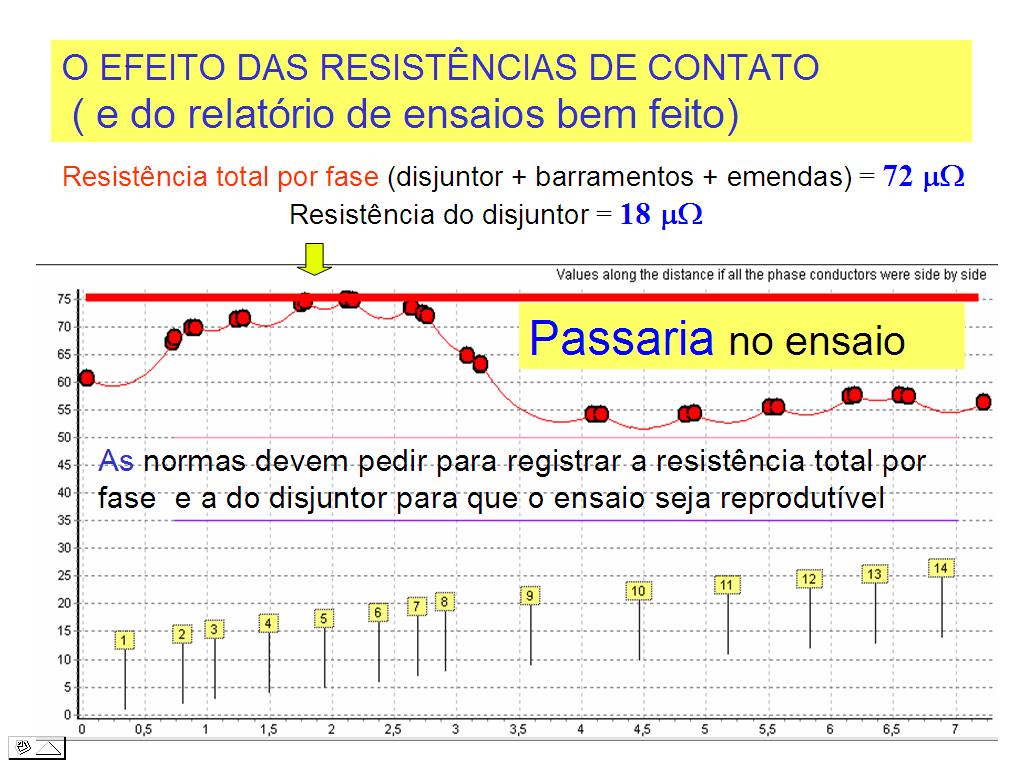
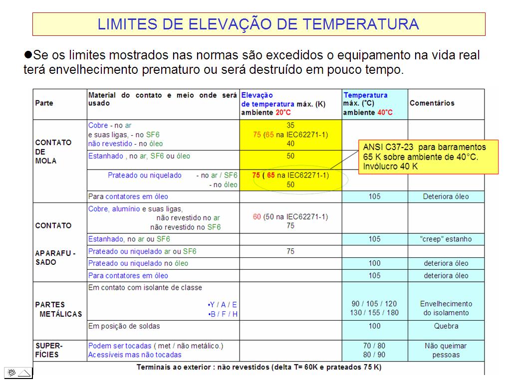
5 TEMPERATURE RISE TEST Fundaments of the values of temperature rise specified in the IEC standards Limits showed in the relevant technical standard; If they are exceeded premature ageing or even destruction of parts may occur. Temperature rise depend on the circulating electric current, the materials involved, and the contact resistances, the ambient air temperature, the air velocity and the geometry of conductors and compartment components. There is an omission in IEC standards for switchgear when they request to measure only the total resistance per phase before the temperature rise test. To enable a test to be reproducible it is necessary to know at least the total resistance per phase AND the contact resistances of the main circuit breaker or switch. As the standard do not emphasize what shall be identified, most test reports issued by laboratories are poor from the point of view of photos and drawings not permitting a reliable comparison between the equipment which was tested and the equipment which is commercialized.

6 TEMPERATURE RISE TEST Fundaments of the values of temperature rise specified in the IEC standards If certain limits specified in the technical standards are exceeded parts may have accelerated aging or even destroyed in a small time
7
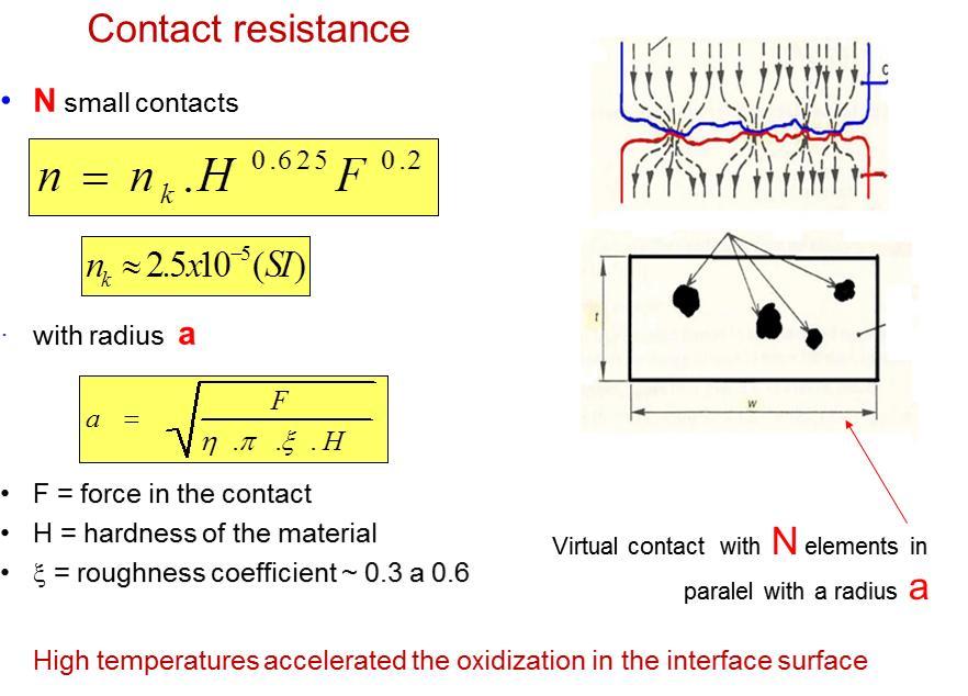
 Constriction resistance Resistance due to the oxide layer in the interface of the contacts 0 = surface resistivity (function of the ( layer")
8 Estimating the contact resistance R c a.. a 2 ( geometry ) Constriction resistance Resistance due to the oxide layer in the interface of the contacts 0 = surface resistivity (function of the ( layer thickness of the oxide = material resistivity a = radius of each small virtual contact n = number of virtual contacts
9 R c Contact resistance a.. a 2 Force = 100 N resistance Constriction = material resistivity a = radius of each small virtual contact n = number of virtual contacts Surface resistance 0 = surface resistivity a x (0.45).(5.5 x10 ) 6 m = 1.78 x 10-8.m 0 = 5 x m 2 R c = = 18
10 Contact resistance for relatively clean surfaces R c = K 1 * F K 2 σ* 0 * F -1 Copper contact silver plated with force 100 N oxidized R c = 88 *10-6 * *10 6 * 5 *10-12 * R c = ( 5, ,2 ) * 10-6 = 16,7 µω

11 TEMPERATURE RISE SIMIULATION GEOMETRY AND MORE INPUT DATA

12 TEMPERATURE RISE SIMIULATION MORE INPUT DATA

13 TEMPERATURE RISE SIMIULATION WITH SERGIO S SOFTWARE The values in the vertical axis are the temperature rise above the external air in each point of the central phase (conductors # 4, # 5 and # 6 represent (phaseperresistanceµω the circuit breaker with 60 The yellow numbers are the numbers of the conductors showed in the figure before as the consductors were aligned side by side

14
15 The effect of the contact resistance and why the standards should request their measurement and not only the total resistance per phase Total resistance per phase (circuit breaker + busbar + connections) = 72 Circuit breaker resistance per phase = 18 APPROVED The numbers in yellow are the number of the conductors in the figure
16 The effect of the contact resistance and why the standards should request their measurement and not only the total resistance per phase Total resistance per phase (circuit breaker + busbar + connections) = 72 Circuit breaker resistance per phase = 30 NOT APPROVED

17 TEMPERATURE RISE CALCULATION (CONCEPTS)
18 ELEVAÇÃO DE TEMPERATURA (fundamentos)
19 TEMPERATURE RISE (CONCEPT USED IN THE SOFTWARE)
20 TEMPERATURE RISE (CONCEPT USED IN THE SOFTWARE)
21 TEMPERATURE RISE (CONCEPT USED IN THE SOFTWARE)

22 TEMPERATURE RISE CALCULATION ΔT s Over the temperature of the surrounding air Te Joule effect Sun light if applicable Eddy currents and similar + W edy Lateral area Radiation losses Convection losses Eddy currents= W eddy = K 1 * B 2 * ω 2 * e 2 volume*ρ* enclosure K 1 = adjustment B = magnetic field ω= 2*π*f e = plate thickness ρ = plate resistivity

23 Atention: this is not suficient to design switchgear

24 TEMPERATURE RISE TEST SIMULATION Bus way of an existing offshore platform 15 kv 3200 A Installation with a high short circuit level 50 KA rms x 125 kacr Bars in the horizontal position are favorable for the electrodynamical forces but an expensive solution for temperature rise

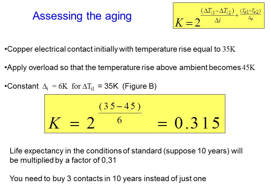
25 Assessing the aging Influence of the temperature (T e1 e T e2 ) and temperature rise (ΔT i1 ΔTand i2 ) in the aging 1 hour of operation in the condition 1 = K x 1 hour of operation in the condition 2 e and i are functions of T i
26
27 SHORT-TIME WITHSTAND CURRENT and PEAK WITHSTAND CURRENT (testing and simulations) Electrodynamical forces, mechanical stresses and supportability of conductors and insulators.
28 Neighbor conductors Current in conductor #1 produce magnetic field B1 Field B1 interact with current I2 in conductor # 2 producing a force Force bend the conductor and is transmited to the insulators
29 Equation for the forces distribution

30 Forces Stresses

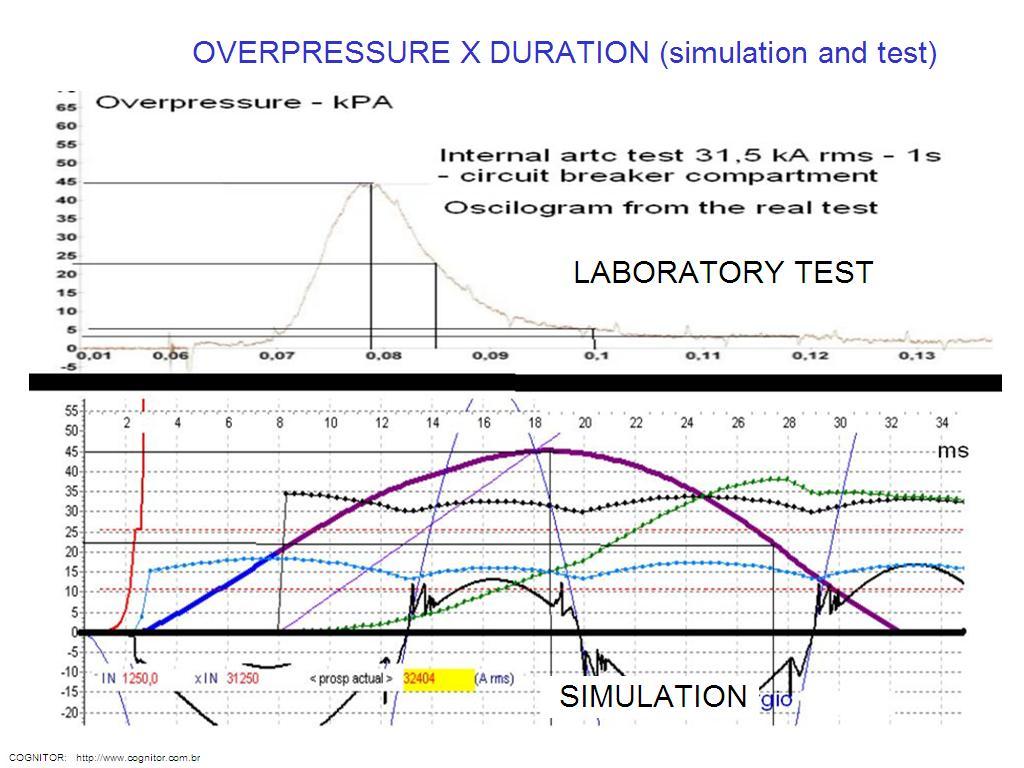
31 INTERNAL ARC TEST Intended to offer a tested level of protection to persons in the vicinity of switchgear in the event of an internal arc. Applicable to high, medium and low voltage equipment. Medium voltage: type test defined in the IEC : classification (IAC, Internal Arc Classification) taking into account the types of accessibility (front, rear and sides) and the effects of the ejected gasses and particles. Fuerzas electrodinámicas y tensiones mecánicas en una celda Low voltage: not a type test but the users request

32 Internal arc test simulation CRITERIA Overpressure Gasses speed Current Arc voltage
33
MAGNETIC & ELECTRIC FIELDS IN SUBSTATIONS AND THEIR EQUIPMENT (Mapping for health legislation and to solve EMC problems).
.") COGNITOR TR 076 / 2016 Page 1 of 37 TECHNICAL REPORT 076 / 2016 http://www.cognitor.com.br/tr076engelectromagfields.pdf TITLE MAGNETIC & ELECTRIC FIELDS IN SUBSTATIONS AND THEIR EQUIPMENT (Mapping for
COGNITOR TR 076 / 2016 Page 1 of 37 TECHNICAL REPORT 076 / 2016 http://www.cognitor.com.br/tr076engelectromagfields.pdf TITLE MAGNETIC & ELECTRIC FIELDS IN SUBSTATIONS AND THEIR EQUIPMENT (Mapping for
THE DIMENSIONING OF ELECTRICAL CONDUCTORS FOR USE IN "PANEL BOARDS" ADDRESSED TO HAZARDOUS AREAS - PART THREE
 July 04 THE DIMENSIONING OF ELECTRICAL CONDUCTORS FOR USE IN "PANEL BOARDS" ADDRESSED TO HAZARDOUS AREAS - PART THREE In this third part. we want to speak about how important is the correct sizing of the
GESELLSCHAFT FÜR ELEKTRISCHE HOCHLEISTUNGSPRÜFUNGEN Mitglied der Short-Circuit-Testing Liaison (STL) Test Report
 Test Report") Mitglied der Short-Circuit-Testing Liaison (STL) Test Report Report-No.: 9725Fr Copy-No.: 00 Contents: 16Sheets Equipment under Test: Manufacturer: Client: Metal-enclosed, single-pole metal-clad and SF
Mitglied der Short-Circuit-Testing Liaison (STL) Test Report Report-No.: 9725Fr Copy-No.: 00 Contents: 16Sheets Equipment under Test: Manufacturer: Client: Metal-enclosed, single-pole metal-clad and SF
VX25 Enclosure System. Technical documentation PE conductor connection, current carrying capacity
 VX Enclosure System Technical documentation PE conductor connection, current carrying capacity Enclosure system VX Contents Contents. General remarks. Introduction. Notes on the design of the earthing
SIMULATIONS AND CALCULATIONS AS VERIFICATION TOOLS FOR DESIGN AND PERFORMANCE OF HIGH-VOLTAGE EQUIPMENT
 21, rue d Artois, F-75008 PARIS A3-210 CIGRE 2008 http : //www.cigre.org SIMULATIONS AND CALCULATIONS AS VERIFICATION TOOLS FOR DESIGN AND PERFORMANCE OF HIGH-VOLTAGE EQUIPMENT M. KRIEGEL, X. ZHU, H. DIGARD,
Thermal-Magnetic Circuit Breaker 2210-S2..
 Thermal-Magnetic Circuit Breaker -S.. Description One, two and three pole thermal-magnetic circuit breakers with trip-free mechanism and toggle actuation (S-type TM CBE to EN 60934/IEC 934). Designed for
Thermal-Magnetic Circuit Breaker 2210-T2...
 Thermal-Magnetic Circuit Breaker 0-T... Description One, two and three pole thermal-magnetic circuit breakers with trip-free mechanism and toggle actuation (S-type TM CBE to EN 6094/IEC 94). Featuring
Thermal-Magnetic Circuit Breaker 2210-S2..
 Thermal-Magnetic Circuit Breaker -S.. Description One, two and three pole thermal-magnetic circuit breakers with trip free mechanism and toggle actuation (S-type TM CBE to EN 6094/IEC 94). Designed for
F F FAULT CURRENT Prospective. 1. Introduction. 2. Types of fault conditions
 FAULT CURRENT F F13-13 FAULT CURRENT - Contents 1. Introduction 2. Types of fault conditions 3 fault current must be determined 3.1 Purposes for which of prospective fault current magnitudes are used 3.2
I, THERMAL ANALYSIS OF BUS-BAR FOR SWITCH BOARD
 THERMAL ANALYSIS OF BUS-BAR FOR SWITCH BOARD Krishna Dwivedi*, Kulwant Dhankar**, Smita Ganjare*** & Hemant More**** Assistant Professor, Mechanical Department, LTCOE, Navi Mumbai, Maharashtra Abstract:
Thermal-Magnetic Circuit Breaker 2210-S2...
 Thermal-Magnetic Circuit Breaker 0-S... Description One, two and three pole thermal-magnetic circuit breakers with trip free mechanism and toggle actuation (S-type TM CBE to EN 60934/IEC 934). Designed
Thermal-Magnetic Circuit Breaker 2210-S2...
 Description One, two and three pole thermal-magnetic circuit breakers with trip free mechanism and toggle actuation (S-type TM CBE to EN 6094/IEC 94). Designed for panel or plug-in mounting. Available
Thermal-Magnetic Circuit Breaker 2210-S2..
 Thermal-Magnetic Circuit Breaker -S.. Description One, two and three pole thermal-magnetic circuit breakers with trip free mechanism and toggle actuation (S-type TM CBE to EN 60934/IEC 934). Designed for
MCB NB1-63H Miniature Circuit Breaker
 NB-H Miniature Circuit Breaker. General. Function protection of circuits against short-circuit currents, protection of circuits against overload currents, switch, isolation, NB-H circuit-breakers are used
Internal Components Forms of Separation
 IEC 60439-1 One or more of the following conditions can be attained by dividing ASSEMBLIES by means of partitions or barriers (metallic or non-metallic) into separate compartments or enclosed protected
Magnetic and Hydraulic-Magnetic Circuit Breaker 8340-T...
 Magnetic and Hydraulic-Magnetic Circuit Breaker 830-T... Description ngle, two and three pole magnetic and hydraulic-magnetic circuit breakers with trip-free mechanism and toggle actuation. A choice of
Masterpact. Installation recommendations
 90 Installation recommendations Presentation Functions and characteristics 9 Dimensions and connection 5 Electrical diagrams 8 Operating conditions 92 Installation in switchboard 9 Door interlock catch
Film Capacitors. EMI suppression capacitors. Date: June 2018
 Film Capacitors EMI suppression capacitors Date: June 2018 EPCOS AG 2018. Reproduction, publication and dissemination of this publication, enclosures hereto and the information contained therein without
Varius SUMMARY OF MODELS OF HRC FUSE-LINKS
 SUMMARY OF MODELS OF HRC FUSE-LINKS Type PNA000 PHNA000 PNA00 PHNA00 Rated current I n up to A up to 0 A up to A up to 0 A Rated voltage U n AC 00 V, 00 V 90 V 00 V 90 V DC 0 V 0 V 0 V 0 V Fuse-link size
16 Appendix 16 Electrical Research Association Report
 Guide to the Wiring Regulations 16 Appendix 16 Electrical Research Association Report (ERA) report on armoured cables with external CPCs The attached report was commissioned by the ECA and is copyright
ISOCON-3 MAINS POWERED ISOLATING SIGNAL CONVERTER
 ISOCON-3 MAINS POWERED ISOLATING SIGNAL CONVERTER CAUTION: This equipment is designed for connection to mains voltages and must be used in accordance with this guide. If it is not, the safety protection
SHORT CIRCUITS IN 3kV DC SYSTEM: STRESSES ON VEHICLES AND INFRASTRUCTURE ELECTRIC EQUIPMENT
 SHORT CIRCUITS IN 3kV DC SYSTEM: STRESSES ON VEHICLES AND INFRASTRUCTURE ELECTRIC EQUIPMENT 1 Gabriele Alessandro ANTONACCI, 2 Paolo MEIATTINI 1 Trenitalia S.p.A., Unità Tecnologie Materiale Rotabile,
ISOCON-6. 24V AC or DC POWERED ISOLATING SIGNAL CONVERTER
 ISOCON-6 24V AC or DC POWERED ISOLATING SIGNAL CONVERTER Whilst every effort has been taken to ensure the accuracy of this document, we accept no responsibility for damage, injury, loss or expense resulting
Modeling of Transmission Line and Substation for Insulation Coordination Studies
 TRAINING DUBROVNIK, CROATIA - APRIL, 27-29 2009 SIMULATION & ANALYSIS OF POWER SYSTEM TRANSIENTS WITH EMTP-RV Modeling of Transmission Line and Substation for Insulation Coordination Studies Prof. Ivo
 ELINEMK Technical Characteristics Rated Current Busbar Code Standards Rated Isolation Voltage Max. Rated Operational Voltage Rated Frequency Pollution Degree Protection Degree External Mechanical Impacts
Analysis of Very Fast Transients in EHV Gas Insulated Substations
 Analysis of Very Fast Transients in EHV Gas Insulated Substations A.Raghu Ram, k. Santhosh Kumar raghuram_a@yahoo.com,ksanthosheee@gmail.com Abstract: Gas insulated switchgear (GIS) has been in operation
SIRCOVER Manual transfer switches from 125 to 3200 A
 Manual transfer switches svr_149_a 3200 A Function are manual multipolar transfer switches with positive break indication. The family includes two ranges: AC for dead time switching (I-0-II), for overlapping
For the electronic measurement of current: DC, AC, pulsed..., with galvanic separation between the primary and the secondary circuit.
 Current Transducer LDSR 0.3-TP/SP1 I P R N = 300 ma For the electronic measurement of current: DC, AC, pulsed..., with galvanic separation between the primary and the secondary circuit. Features Closed
BETA Protecting. Low-Voltage Fuse Systems. LV HRC fuse links. 3/36 Siemens ET B1 2008
 LV HRC fuse links Overview LV HRC fuses are used for installation systems in non-residential, commercial and industrial buildings as well as in switchboards of power supply companies. They therefore protect
3-D Thermal Field Analysis of 10kV High Voltage Switchgear
 2017 2nd International Conference on Manufacturing Science and Information Engineering (ICMSIE 2017) ISBN: 978-1-60595-516-2 3-D hermal Field Analysis of 10kV High Voltage Switchgear Jinpeng Chen, Zhaowei
Periodic Inspection and Testing of Electrical Installations Sample Test ( ) Version 1.3 July 2018
 Version 1.3 July 2018") Periodic Inspection and Testing of Electrical Installations Sample Test (2391-051) Version 1.3 July 2018 Sample Questions Version and date Change detail Section 1.3 July 2018 Modified questions/answers
Periodic Inspection and Testing of Electrical Installations Sample Test (2391-051) Version 1.3 July 2018 Sample Questions Version and date Change detail Section 1.3 July 2018 Modified questions/answers
ELECTRICAL AND THERMAL DESIGN OF UMBILICAL CABLE
 ELECTRICAL AND THERMAL DESIGN OF UMBILICAL CABLE Derek SHACKLETON, Oceaneering Multiflex UK, (Scotland), DShackleton@oceaneering.com Luciana ABIB, Marine Production Systems do Brasil, (Brazil), LAbib@oceaneering.com
TeSys circuit-breakers
 Presentation Thermal-magnetic motor circuit-breakers types GV2, GV and GV7 GV2-ME, GV2-P, GV-ME and GV7-R motor circuit-breakers are -pole thermal-magnetic circuit-breakers specifically designed for the
Fault Calculation Methods
 ELEC9713 Industrial and Commercial Power Systems Fault Calculation Methods There are two major problems that can occur in electrical systems: these are open circuits and short circuits. Of the two, the
Single Core XLPE/LSF/AWA/LSF Power Cable
 Single Core XLPE/LSF/AWA/LSF Power Cable 00/00V and 100/00V Application LSF insulated, armoured and sheathed, single core power cable for use in fixed installations. Especially for use in areas where fire
COPPER FOR BUSBARS CHAPTER 4: SHORT-CIRCUIT EFFECTS
 European Copper Institute COPPER FOR BUSBARS CHAPTER 4: SHORT-CIRCUIT EFFECTS David Chapman August 2011 ECI Available from www.leonardo-energy.org Document Issue Control Sheet Document Title: Publication
TEST CERTIFICATES OR REPORTS ISSUED BY VEIKI-VNL LTD.
 Page 2 of 29 TEST CERTIFICATES OR REPORTS ISSUED BY LTD. Type Test Certificate of Complete Type Test This certificate provides the verification of all the rated characteristics of the equipment as assigned
Electrical installation solutions for buildings Technical details Arc Fault Detection Devices
 /1 Electrical installation solutions for buildings Technical details Arc Fault Detection Devices Index Functions and classification criteria for AFDD /2 Power loss, derating and performance in altitude
TECHNICAL INFORMATION
 TECHNICAL INFORMATION RATED PRIMARY OLTAGE () This is the supply assigned to the transformer by the manufacturer. RATED SECONDARY OLTAGE () This is the secondary output assigned to the transformer when
Superconducting Fault Current Limiters
 Superconducting Fault Current Limiters First Friday Club 1 st April 2011 Gerhard Novak UK Technical Manager Joachim Bock Managing Director, Nexans Superconductors 1 Smart Grid Solutions 2 Fault current
1. Explain the various methods of methods of grounding. In power system, grounding or earthing means connecting frame of electrical equipment (non-cur
 1. Explain the various methods of methods of grounding. In power system, grounding or earthing means connecting frame of electrical equipment (non-current carrying part) or some electrical part of the
For the electronic measurement of current: DC, AC, pulsed..., with galvanic separation between the primary and the secondary circuit.
 Current Transducer HO-NP series I P N = 4, 6, 12, 15 A Ref: HO 4-NP, HO 6-NP, HO 12-NP, HO 15-NP For the electronic measurement of current: DC, AC, pulsed..., with galvanic separation between the primary
SPECIFICATION SS 51/9 400KV COUPLING CAPACITORS FOR POWER LINE CARRIER SYSTEM
 INDEPENDENT POWER TRANSMISSION OPERATOR S.A. TNPRD/ SUBSTATION SPECIFICATION & EQUIPMENT SECTION January 2017 SPECIFICATION SS 51/9 400KV COUPLING CAPACITORS FOR POWER LINE CARRIER SYSTEM I. SCOPE This
ATyS Automatic and remotely operated transfer switches from 125 to 3200 A
 atys-p_001_b atys_d_001_a_1_cat ATyS p I-0-II 4P ATyS d I-0-II 4P Function The ATyS are three-phase motorised transfer switches with positive break indication. They enable the on load transfer of two three-phase
Issued August DATA SHEET. 3VT3 MCCB up to 630 A
 ssued August 9 DATA SHEET VT MCCB up to 6 A Based on Siemens Catalog V 6 8 Circuit breakers Switch disconnectors Technical specifications Specifications Type VT 76-AA6/6/56-AA, VT 76-AA6/6/56-AA Circuit
Chapter 3: Fundamentals of Mechanics and Heat. 1/11/00 Electromechanical Dynamics 1
 Chapter 3: Fundamentals of Mechanics and Heat 1/11/00 Electromechanical Dynamics 1 Force Linear acceleration of an object is proportional to the applied force: F = m a x(t) F = force acting on an object
High-ohmic/high-voltage resistors
 FEATURES These resistors meet the safety requirements of: UL1676 (range 510 kω to 11 MΩ) EN60065 BS60065 (U.K.) NFC 92-130 (France) VDE 0860 (Germany) High pulse loading capability Small size. APPLICATIONS
Semiconductor (AC) fuses
 fuses") PSC gr sizes 7x - 690 VAC Main characteristics 6,9 grb 71 PA 200 6,9 grb 73 TTF 1000 + MS7V1-5 UR Ferraz Shawmut PSC-gRB 690 VAC fuse-links provide maximum flexibility in equipment design and ultimate
PSC gr sizes 7x - 690 VAC Main characteristics 6,9 grb 71 PA 200 6,9 grb 73 TTF 1000 + MS7V1-5 UR Ferraz Shawmut PSC-gRB 690 VAC fuse-links provide maximum flexibility in equipment design and ultimate
440V 500V V / / /2 12.
 -26 Manual Motor Protectors March 0 B-Frame D-Frame Table -6. XTPR Rotary Manual Motor Protectors with Screw Terminals Global Ratings and North American Ratings Type and Type 2 Coordination Motor Protective
Operating instructions Pressure sensor PN / / 2007
 Operating instructions Pressure sensor PN42 704298 / 00 0 / 2007 Contents afety instructions... 3 2 Function and features... 4 3 Function... 5 3. witching function... 5 4 Installation... 5 5 Electrical
Request Ensure that this Instruction Manual is delivered to the end users and the maintenance manager.
 Request Ensure that this Instruction Manual is delivered to the end users and the maintenance manager. 1 -A - Introduction - Thank for your purchasing MITSUBISHI ELECTRIC MELPRO TM D Series Digital Protection
5SJ4...-.HG Circuit Breakers to IEC and UL 489
 Siemens AG 009 5SJ...-.HG Circuit Breakers to IEC and UL 89 BETA Low-Voltage Circuit Protection Compliance with industry standards is a must in today's manufacturing environment. Worldwide acceptance is
Digital Current Transducer HO-SW series I P N = A. Ref: HO 100-SW; HO 150-SW; HO 200-SW; HO 250-SW
 Digital Current Transducer HO-SW series I P N = 100... 250 A Ref: HO 100-SW; HO 150-SW; HO 200-SW; HO 250-SW Bitstream output from on onboard Sigma Delta modulator. For the electronic measurement of current:
NYY-J/-o 34 NYCWY 36 NYCY 37 NAYY 38
 NYY-J/-o 34 NYCWY 36 NYCY 37 NAYY 38 NYY-J/-O Energy and control cable acc. to DIN VDE 0276 and HD 603 Application Indoor and outdoor installation, laying in ducts and underground, for power stations,
3VT4 Molded Case Circuit Breakers up to 1000 A
 VT4 Molded Case Circuit Breakers up to 00 A Catalog Technical nformation VT4 Molded Case Circuit Breakers up to 00 A General data / - Overview Circuit breakers Switch disconnectors / - Selection and ordering
Simple Improved Equations for Arc Flash Hazard Analysis
 Simple mproved Equations for Arc Flash Hazard Analysis Dr. obert Wilkins Electrical Engineering Consultant, Heswall, UK, bob@overdee.demon.co.uk Keywords: Arc flash analysis, arcing current, incident energy
Impedance relay and protection assemblies
 RXZK 21H, 22H, 23H 509 006-BEN Page 1 Issued June 1999 Changed since July 1998 Data subject to change without notice (SE970175) (SE970184) Features Micro-processor based impedance relay with R and X settings
Thermal studies for HV GIS compartment design
 hermal studies for H GS compartment design Mariusz Stosur Pawel Dawidowski Marcin Szewczyk Przemyslaw Balcerek ABB Corporate Research Center, Poland Kacper Sowa AGH University of Science and echnology,
FEATURES APPLICATIONS DESCRIPTION QUICK REFERENCE DATA. PILKOR components
 FEATURES Excellent anti-surge characteristics Stable characteristics to moisture resistance even in high resistance range. Good replacement for ceramic plate resistors. APPLICATIONS Telecommunication Industrial
EXEMPLAR NATIONAL CERTIFICATE (VOCATIONAL) ELECTRICAL PRINCIPLES AND PRACTICE NQF LEVEL 3 ( ) (X-Paper) 09:00 12:00
 ELECTRICAL PRINCIPLES AND PRACTICE NQF LEVEL 3 ( ) (X-Paper) 09:00 12:00") NATIONAL CERTIFICATE (VOCATIONAL) ELECTRICAL PRINCIPLES AND PRACTICE NQF LEVEL 3 2008 (12041002) (X-Paper) 09:00 12:00 EXEMPLAR This question paper consists of 7 pages. EXEMPLAR -2- NC(V) TIME: 3 HOURS
NATIONAL CERTIFICATE (VOCATIONAL) ELECTRICAL PRINCIPLES AND PRACTICE NQF LEVEL 3 2008 (12041002) (X-Paper) 09:00 12:00 EXEMPLAR This question paper consists of 7 pages. EXEMPLAR -2- NC(V) TIME: 3 HOURS
Evaluation of the risk of failure due to switching overvoltages of a phase to phase insulation
 Evaluation of the risk of failure due to switching overvoltages of a phase to phase insulation A. Xemard, J. Michaud, A. Guerrier, I. Uglesic, G. Levacic, M. Mesic Abstract-- The upgrade of an overhead
DEPARTMENT OF ELECTRICAL AND ELECTRONICS ENGINEERING QUESTION BANK
 DEPARTMENT OF ELECTRICAL AND ELECTRONICS ENGINEERING QUESTION BANK SUBJECT CODE & NAME: EE 2303 - TRANSMISSION & DISTRIBUTION YEAR / SEM: III/V UNIT-I TRANSMISSION SYSTEM INTRODUCTION PART-A 1. What is
PREDICTION OF TEMPERATURE VARIATIONS FOR INDUSTRIAL BUS DUCT SYSTEM UNDER FORCED CONVECTION COOLING WITH VARIOUS ASPECT RATIOS USING MATLAB
 International Journal of Mechanical Engineering and Technology (IJMET) Volume 9, Issue 2, February 2018, pp. 734 741 Article ID: IJMET_09_02_076 Available online at http://www.iaeme.com/ijmet/issues.asp?jtype=ijmet&vtype=9&itype=2
90 MCB range Modular circuit breakers for circuit protection
 MCB - MTC - MT - MTHP Technical data TYPE MTC MT MTC45 MTC60 MTC100 MT 45 MT 60 Rated current (In) (A) 2-32 6-32 6-32 6-40 1-63 Utilization category A A A A A Rated operational voltage (Ue) (V) 230 / 400
For the electronic measurement of current: DC, AC, pulsed..., with galvanic separation between the primary and the secondary circuit.
 Current Transducer HO-NP/SP33 series I PN = 8, 15, 25 A Ref: HO 8-NP/SP33, HO 15-NP/SP33, HO 25-NP/SP33 For the electronic measurement of current: DC, AC, pulsed..., with galvanic separation between the
90 MCB MODULAR CIRCUIT BREAKERS FOR CIRCUIT PROTECTION
 MCB - MTC - MT - MTHP Technical data TYPE MTC MT MTC45 MTC60 MTC100 MT 45 MT 60 Rated current (In) (A) 2-32 6-32 6-32 6-40 1-63 Utilization category A A A A A Rated operational voltage (Ue) (V) 230/400-240/415
S R O T C U D IN & MYRRA
 TRANSFORMERS & INDUCTORS MYRRA...Of course! TECHNICAL INFORMATION RATED PRIMARY OLTAGE () This is the supply assigned to the transformer by the manufacturer. RATED SECONDARY OLTAGE () This is the secondary
THERMAL BEHAVIOR OF DISTRIBUTION TRANSFORMERS IN SUMMERTIME AND SEVERE LOADING CONDITIONS
 THERMAL BEHAVIOR OF DISTRIBUTION TRANSFORMERS IN SUMMERTIME AND SEVERE LDING CONDITIONS Cesare RAVETTA Massimo SAMANNA Angelo STUCCHI Antonio BOSSI Aem Elettricità Italy Aem Elettricità Italy Aem Calore
C60N circuit breakers0 B, C and D curves IEC 60898: 6000 A, IEC : 10 ka
 C0N circuit breakers0 B, C and s IEC 0898: 000 A, IEC 097-: 0 ka Function b The circuit-breakers combine the following functions: v protection of circuits against short-circuit currents v protection of
Hydra Fault Current Limiting HTS Cable to be Installed in the Consolidated Edison Grid
 Hydra Fault Current Limiting HTS Cable to be Installed in the Consolidated Edison Grid J. McCall, J. Yuan, D. Folts, N. Henderson, American Superconductor D. Knoll, Southwire M. Gouge, R. Duckworth, J.
Dr. Michael Müller. Thermal Management for LED applications
 Thermal Management for LED applications Content Thermal Design Basics thermal management Internal thermal management External thermal management 2 1967 founded with the production of insulation parts for
High Ohmic/High Voltage Resistors
 High Ohmic/High Voltage Resistors VR68 A metal glazed film is deposited on a high grade ceramic body. After a helical groove has been cut in the resistive layer, tinned electrolytic copper wires are welded
ELECTRO MAGNETIC INDUCTION
 ELECTRO MAGNETIC INDUCTION 1) A Circular coil is placed near a current carrying conductor. The induced current is anti clock wise when the coil is, 1. Stationary 2. Moved away from the conductor 3. Moved
Ref: HLSR 16-PW; HLSR 32-PW; HLSR 40-PW-000; HLSR 50-PW-000,
 Digital Current Transducer HLSR-PW series I P N = 16... 50 A Ref: HLSR 16-PW; HLSR 32-PW; HLSR 40-PW-000; HLSR 50-PW-000, Bitstream output from on onboard Sigma Delta modulator. For the electronic measurement
Transient thermal measurements and thermal equivalent circuit models
 AN 2015-10 Transient thermal measurements and thermal equivalent circuit Replaces AN2008-03 About this document Scope and purpose The basis of a power electronic design is the interaction of power losses
Extensions to the Finite Element Technique for the Magneto-Thermal Analysis of Aged Oil Cooled-Insulated Power Transformers
 Journal of Electromagnetic Analysis and Applications, 2012, 4, 167-176 http://dx.doi.org/10.4236/jemaa.2012.44022 Published Online April 2012 (http://www.scirp.org/journal/jemaa) 167 Extensions to the
Varius SUMMARY OF MODELS OF HRC FUSE-LINKS. Type PVA10 / PV10 PV14 PV22 Rated current I n up to 32 A up to 63 A up to 125 A Rated voltage U n
 Varius SUMMARY OF MODELS OF HRC FUSE-LINKS Type A / Rated current I n up to A up to up to A Rated voltage U n AC V, V V, V, 9 V V, V, 9 V DC V V V Fuse-link size x8 x x8 Utilization category of the fuse-link
M I N I S T R Y O F C O M M U N I C A T I O N S T E L E C O M M U N I C A T I O N S S E C T O R T E C H N I C A L S T A N D A R D F O R
 M I N I S T R Y O F C O M M U N I C A T I O N S T E L E C O M M U N I C A T I O N S S E C T O R T E C H N I C A L S T A N D A R D F O R M A T E R I A L S N O. G 2 0 : 1 0 : 0 0 1 : 1 8 J U M P E R W I
Issued August DATA SHEET. 3VT5 MCCB up to 1600 A
 ssued August 9 DATA SHEET VT5 MCCB up to 0 A Based on Siemens Catalog V 8 Standard circuit breakers Releases Technical specifications Specifications VT5 circuit breakers Switch disconnectors Type Standards
EPR Insulated, Heavy Duty HOFR Sheathed Flexible Cables
 1 EPR Insulated, Heavy Duty HOFR Sheathed Flexible Cables 0 C 0/0 V *TQ Application For power/lighting services and mains supply or extension leads in situations requiring frequent handling, trailing and
For the electronic measurement of current: DC, AC, pulsed..., with galvanic separation between the primary and the secondary circuit.
 Current Transducer HO-NSM series I PN = 8, 15, 25 A Ref: HO 8-NSM, HO 15-NSM, HO 25-NSM For the electronic measurement of current: DC, AC, pulsed..., with galvanic separation between the primary and the
Fire Resistant Armoured Power Cable
 Power and Wiring Cables Fire Resistant Armoured Power Cable 00/00V Application Armoured fire resistant cable for use in fixed wiring installations where it is necessary for the cable to retain circuit
Table of Contents Pin-Configuration Selection Guide for HDE, HDS, & EFP
 Table of Contents -Configuration Selection Guide for HDE, HDS, & EFP Service Voltage Rating... Electrical Service Ratings... Ampacity Ratings by Contact... Electrical Service Ratings Explained... Operating
TYPE. max. working voltage 250 V 350 V 500 V 750 V. max. overload voltage 500 V 700 V 1000 V 1500 V. basic specifications IEC B
 FEATURES Non inductive High pulse loading capability. APPLICATIONS Application for overload and high voltage surge hazard circuits. DESCRIPTION A carbon film is deposited on a high grade ceramic body.
VKES. Contents. Page 2 No 213, 13th Main RBI Layout JP Nagar 7th Phase, Bangalore Vidyuth Kanti Engineering Services
 Contents What is earthing... 4 Why do we do earthing... 4 What is the Scope of this guideline... 4 How to protect a person in a substation against electrical shock... 4 What happens during a fault... 4
CAPACITORS. February Ultra high voltage ceramic capacitors. With metal terminals For GCB/GIS. TSF/H/GA series
 February 217 Ultra high voltage ceramic capacitors With metal terminals For GCB/GIS TSF/H/GA series (2/6) REMINDERS FOR USING THESE PRODUCTS (1) During transportation and storage Do not transport or store
Chapter 6: Efficiency and Heating. 9/18/2003 Electromechanical Dynamics 1
 Chapter 6: Efficiency and Heating 9/18/2003 Electromechanical Dynamics 1 Losses As a machine transforms energy from one form to another there is always a certain power loss the loss is expressed as heat,
Effects of Capacitor Bank Installation in a Medium Voltage (MV) Substation
 Substation") Effects of Capacitor Bank Installation in a Medium Voltage (MV) Substation Adesina, Lambe Mutalub Department of Engineering & Standardization, Eko Electricity Distribution Plc, 24/25, Marina, Lagos Island,
Effects of Capacitor Bank Installation in a Medium Voltage (MV) Substation Adesina, Lambe Mutalub Department of Engineering & Standardization, Eko Electricity Distribution Plc, 24/25, Marina, Lagos Island,
Siemens AG Miniature Circuit Breakers. Totally Integrated Power SENTRON. Configuration. Edition 10/2014. Manual. siemens.
 Siemens AG 05 Totally Integrated Power SENTRON Configuration Manual Edition 0/0 siemens.com/lowvoltage Siemens AG 05 Siemens AG 05 Introduction 5SL miniature circuit breakers 5SY and 5SP miniature circuit
MR medium rating busbar
 technical information General features MR is fully compliant with S EN 0-, specifically, the rated current of the Zucchini busbar trunking systems is always rated at the average ambient temperature of
Three Core XLPE/LSF/SWA/LSF Power Cable
 1 Three Core XLPE/LSF/SWA/LSF Power Cable./ kv Application LSF armoured power cable for use in fixed installations. Especially for use in areas where fire would create dense smoke and toxic fumes causing
International Journal on Technical and Physical Problems of Engineering (IJTPE) Published by International Organization of IOTPE
 Published by International Organization of IOTPE") International Journal on Technical and Physical Problems of Engineering (IJTPE) Published by International Organization of IOTPE ISSN 2077-3528 IJTPE Journal www.iotpe.com ijtpe@iotpe.com September 2013
International Journal on Technical and Physical Problems of Engineering (IJTPE) Published by International Organization of IOTPE ISSN 2077-3528 IJTPE Journal www.iotpe.com ijtpe@iotpe.com September 2013
Science Practice Exam. Chapters 5 and 14
 Science Practice Exam Chapters 5 and 14 FORMULAS Science and Technology FORMULAS C: concentration m: quantity of solute v: quantity of solution V: potential difference R: resistance I: electric current
Lecture PowerPoints. Chapter 18 Physics: Principles with Applications, 6 th edition Giancoli
 Lecture PowerPoints Chapter 18 Physics: Principles with Applications, 6 th edition Giancoli 2005 Pearson Prentice Hall This work is protected by United States copyright laws and is provided solely for
Temperature. 3
 Temperature In 1848, Sir William Thomson (Lord Kelvin) stated the zero principle of dynamics. This principle enabled him to define thermodynamic temperature and to establish an objective method of measuring
Modeling and Simulation of Air Insulated and Gas Insulated Substations
 International Journal of Electrical Engineering. ISSN 0974-2158 Volume 11, Number 2 (2018), pp. 177-187 International Research Publication House http://www.irphouse.com Modeling and Simulation of Air Insulated
Inductance at fl at point at 25 C. Tol. L1 (μh) (%) (%) min. min. max. ETQP6F1R2HFA 1.2 ±30 ETQP6F2R0HFA ETQP6F3R2HFA 4.
 (%) (%) min. min. max. ETQP6F1R2HFA 1.2 ±30 ETQP6F2R0HFA ETQP6F3R2HFA 4.") Power Choke Coil Series: PCC-F126F (N6) Thin, compact and high power Features High power (Isat 20 A /100 C) Thin profi le (5.7 mm height)/smd Low leakage fl ux RoHS compliant Recommended Applications DC-DC
Power Choke Coil Series: PCC-F126F (N6) Thin, compact and high power Features High power (Isat 20 A /100 C) Thin profi le (5.7 mm height)/smd Low leakage fl ux RoHS compliant Recommended Applications DC-DC
SKF actuators available for quick delivery. Selection guide
 SKF actuators available for quick delivery Selection guide A wide range of SKF actuators available for quick delivery Industrial actuator 24 Volt DC Load range 1 000 to 4 000 N Speed range 5 to 52 mm/s
C120N circuit-breakers B, C and D curves EN 60898/EN 61009: IEC : 10 ka
 C0N circuit-breakers B, C and D curves EN 09/EN 009: 0000 - IEC 097-: 0 ka function # protection of cables against overloads and short-circuits in final distribution # manual control and isolation # earth
AC axial fan. Limited partnership Headquarters Mulfingen Amtsgericht (court of registration) Stuttgart HRA
 Stuttgart HRA") ebm-papst Mulfingen GmbH & Co. KG Bachmühle D-767 Mulfingen Phone +9 798 8-0 Fax +9 798 8-0 info@de.ebmpapst.com www.ebmpapst.com Limited partnership Headquarters Mulfingen Amtsgericht (court of registration)
ebm-papst Mulfingen GmbH & Co. KG Bachmühle D-767 Mulfingen Phone +9 798 8-0 Fax +9 798 8-0 info@de.ebmpapst.com www.ebmpapst.com Limited partnership Headquarters Mulfingen Amtsgericht (court of registration)