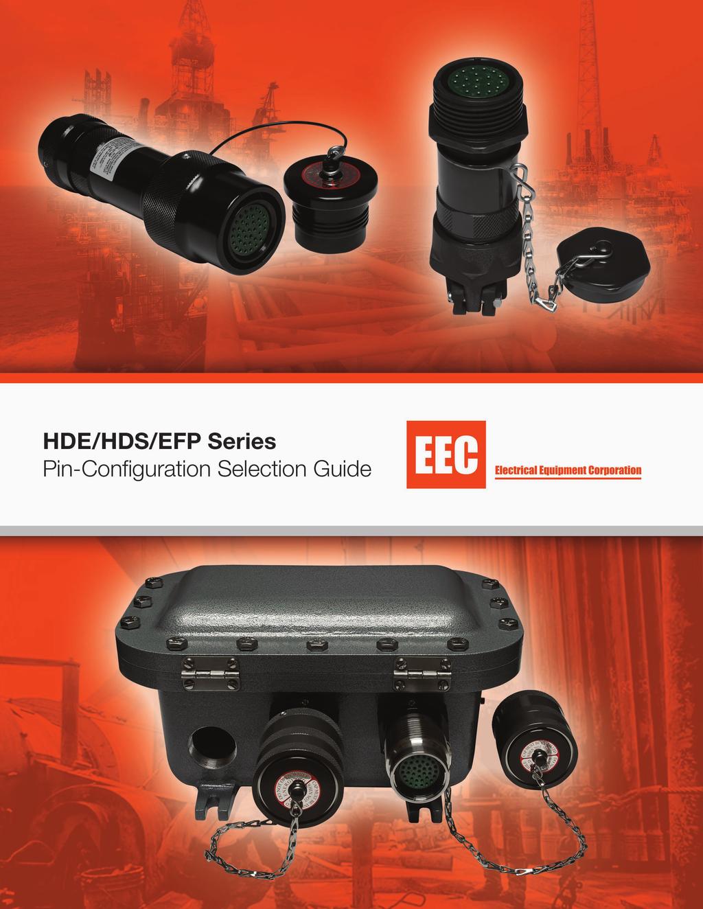
Table of Contents Pin-Configuration Selection Guide for HDE, HDS, & EFP
|
|
|
- Lambert Williams
- 6 years ago
- Views:
Transcription
1
2 Table of Contents -Configuration Selection Guide for HDE, HDS, & EFP Service Voltage Rating... Electrical Service Ratings... Ampacity Ratings by Contact... Electrical Service Ratings Explained... Operating Temperature Classification... Connector Selection Guide... Configuration Listing & Identification Connector Grounding Systems & Horsepower Ratings....0 Contact...- Contacts...- Contacts...- Contacts...-0 Contacts...- Contacts...- Contacts...- Contacts... 0 Contacts...-, Contacts... Contacts...-0, Contacts...0 Contacts... Contacts...- 0, Contacts..., Contacts... Contacts...- Contacts... Contacts...- Contacts ,, Contacts... Contacts...- 0, Contacts , 0 Contacts...,,, Contacts...0, 0 Contacts Contacts...-
3 Service Voltage Ratings: IEC & EC Contact/Wire s in AWG & Metric (mm²) & Grounding Method Identification Grounding Contact ination Symbol Solder Well Pressure Crimp Service Voltage Ratings IEC Ratings EC Ratings Symbol DC Volts AC Volts instrumentation A D E 0 0 B 0 0 C Symbol DC Volts AC Volts instrumentation - - A 00 D E B C OTE: IEC Service Voltage Ratings are not for circuit-breaking applications, frequency listing at 0, 0, and 00Hz Contact Symbol/Wire Multipin Contact s Contact Symbols Wire AWG AWG AWG 0 AWG AWG AWG /0 AWG /0 AWG 0 MCM Metric (mm²) mm mm mm mm mm mm mm mm mm Single Pole Contact s Contact Symbols Wire /0 AWG MCM MCM MCM MCM 00 MCM MCM MCM MCM MCM Metric (mm²) 0 0 mm mm mm mm mm mm mm mm mm mm
.")
 AC (V) on- Circuit Breaking DC (V)")

4 Electrical Service Ratings Arrangement Service Rating - Table Each insert plan form has a factory designated working voltage rating. The voltage allowable through the contacts, male and female, is limited by the dielectric separation between each contact and the nearest conductor (adjacent contacts and the connector shell). A letter in Column represents voltage ratings, with their associated maximum values, both AC and DC. The insert plan form listings show the ratings for each individual insert. Military Ratings IEC MIL-C-0H Required Minimum EC Ratings Service Specifications Creepage Distance Ratings on-circuit Breaking Electrical Service Voltage DC (V) AC (V) on- Circuit Breaking DC (V) Circuit Breaking AC (V) *I = Instrumentation EC, MS Values based on RMS using MIL-C-0H Table, XVIII working voltage, IEC values based on 0- table b. IEC Service Ratings circuit breaking is not permissable in IEC standards without a hot disconnet permit. Required Minimum Clearance or Through Air Spacing DC (V) AC (V) in mm in mm I / - - A / / D / / E / / B / / C / Alternative Classifications of Current Rating Military Current Ratings According to MIL-C-0 The maximum current carrying capability of a contact pair is determined by the basic design of the contacts and also the ability of the insulation to withstand the temperature rises caused by an increase in current. The connector is rated up to ºC (ºF) for continuous operation. The actual working temperature is a function of the ambient temperature and the summation of the heat dissipated by each individual contact. The maximum current rating for continuous supply is calculated from temperature of the insert. See Column in the above table. EC (ational Electrical Code) on-circuit Breaking Table, on the following page, lists ratings that are based on test results of contacts and connectors. The temperature range must fall within the range specified by Underwriters Laboratories Inc., assuming certain wire sizes. IEC Service Voltage Ratings on-circuit Breaking Service voltage ratings as designated by IEC are derived from IEC 0- Table b. When ascertaining required values for creepage and clearance voltages may be increased by a factor of. to accommodate the range in common use. Table, on the following page, lists these ratings.


 - -.00. AWG (. mm² ) 0.. AWG (. mm² ) 0 0 0. 0. 0 AWG (.")
 00 0. 0.0 MCM ( mm² ) - - 0.0 A MCM ( mm² ) - - 0.")
 - 0-0 0.0 A MCM ( mm² ) - - 0.")
5 Ampacity Ratings by Contact (Gauge) AWG, MCM, and mm Table : The following pages, and, apply to table below. Contact s #AWG MCM ( mm² ) Ampacity Rating on-circuit Breaking EC Ampacity Rating IEC Ampacity Rating on-circuit Breaking on-circuit Breaking Contact Resistance Milliohms (mw) MS EC Crimp Solder AWG (.0 mm² ) AWG (. mm² ) 0.. AWG (. mm² ) AWG (. mm² ) AWG (. mm² ) AWG ( mm² ) /0 AWG ( mm² ) /0 AWG (0 mm² ) MCM ( mm² ) A MCM ( mm² ) A 0 MCM ( mm² ) A MCM ( mm² ) A 00 MCM (0 mm² ) A MCM ( mm² ) A MCM ( mm² ) A MCM ( mm² ) A MCM ( mm² ) A
6 Electrical Service Ratings Explained On previous page, see 'Table ' header for notations: states Assumptions and Standards: Contact sizes: assume equal wire size included as contact and wire combination. Differing wire sizes will exhibit different electrical performance results. MS Specification (MIL-C-0D) current ratings are in accordance with MIL-C-0D EC Specifications assume a wire size selection that is in accordance EC guidelines for temperature rise. All ampacities shown are for individual contacts and must be derated to determine maximum total current to be carried by the connector. Use the tables and formulas detailed on pages: and Different ambient temperatures need to be taken into consideration when considering ampacity ratings, depending on application and the intended location to be used. It is particularly important to derate the connector when being used in hazardous locations. EC circuit breaking capability: connectors and contacts that have demonstrated the ability to rupture current under full rated load in accordance with UL standard, and MIL-C-E. EC circuit breaking for hazardous locations (Class and Division system) Connectors and contacts have demonstrated the ability to disconnect under full rated load in accordance with UL standard, and CSA C.--M IEC ampacity ratings: assume equal wire size, included as contact and wire combination. Differing wire sizes will exhibit different electrical performance results. Contact Resistance when tested in accordance with MIL- method 00. will not exceed the values listed in table column
7 Operating Temperature Classifications in Ambient Temperatures Wire current ratings: For a more conservative standard use the hazardous location derating formulas detailed on pages and. Hazardous locations: The following standards IEC derating per: IEC 00-0 :00 General requirements IEC 00- :00 Flameproof protection 'd' IEC 00- :00 Increased Safety protection 'e' These standards require that equipment in an energized condition does not exceed the rated surface temperature in order not to ignite hazardous atmospheres. These values are listed below in 'Table.' The formulas detailed on pages and will be of assistance to determine the correct insert and allowable ampacity for the connector application and location the value is expressed as dissipated wattage. Table IEC vs EC Temperature Classification Temp in C IEC Classification. America T T 00 T T 0 T TA T T 0 T TC T TB 0 T TA 00 T T T TD 0 T TC 0 T TB 0 T TA 00 T T 0 T T OTE: This table clarifies the differences in temperatures classification between IEC and EC, the orth American Standard Table IEC Safe Equipment Operating Temperatures Spontaneous Ignition Temp of the Gasses (T) T C Temperature Class of Equipment T 00 C T C T 00 C T 00 C T 0 C < T < < T < < T < < T < 00 Equipment Explosion Risk 00 < T < 0 Equipment Safe for Use 0 < T
8 Connector Selection Guide Maximum Allowable Wattages & Contact Resistance Values Table - Maximum Allowable Dissipated Wattage Connector Upper Ambient Temperature of +0 C Upper Ambient Temperature of +0 C Upper Ambient Temperature of + C Temperature Class Temperature Class Temperature Class T T T T T T Maximum Allowable Dissipated Wattage OTE: Please pay careful attention to the ambient temperature and also the temperature classification. Connectors are marked T unless otherwise requested. Table - Contact Resistance Values Contact Contact Resistance (milliohms mw) Soldered Crimped Contact Current Rating (amps) AWG (.0mm²)..00 AWG (.mm²).. AWG (.mm²) AWG (.mm²) AWG (.mm²) AWG (mm²) /0 AWG (mm²) /0 AWG (0mm²) Contact Contact Resistance (milliohms mw) Soldered Crimped Contact Current Rating (amps) MCM (mm²) A 0.0 MCM (mm²) A MCM (mm²) A 0.00 MCM (mm²) A 0.0 MCM (mm²) A 0.0 MCM (mm²) A MCM (mm²) A 0.00 MCM (mm²) A OTE: Contact Resistance measured in accordance with MIL-Std A, Method 00. Contact Resistance value expressed in milliohms mw for Table and Table. IMPORTAT To select the shell size of the connector, it is essential that you calculate the dissipated wattage of the arrangement. This ensures that the arrangement does not exceed the maximum permitted temperature classification with regard to the upper ambient temperature for the area of installation. In some cases it will be necessary to either derate the allowed ampacity of each contact or increase the shell size of the connector. Refer to Table about the maximum allowable dissipated wattage per connector size and use the calculations below to determine safe and proper working temperature of the chosen electrical connector.


9 Configuration Listing & Identification HDE, HDS and EFP Electrical Connector Service Rating The HDE, HDS and EFP Configuration listing is used primarily to identify various contact insert arrangements. For the engineer, it provides visual selection of the insert configuration needed to satisfy his other requirements. For the end user, the list provides general information useful in the termination of plugs and receptacles. To aid the reader, the insert configuration are presented in numerical order, based on the number of contacts in each insert. Contact Symbol Figure Available Alternate Key Positions Contact Location umbers Figure - Illustration Configuration The male insert illustration shown left (and those on the following pages) is shown as it appears when viewed from the front. Contacts are shown by both physical position within the configuration and by contact number. The contact number corresponds to the contact position shown on the rear face of the insert illustrated as well as to both the front and rear faces of the mating insert. The symbol used to show contact location is indicative of contact size. For example, the contact symbol in this illustration represents a # (.mm²) contact. An explanation of contact symbols is presented on each page of the listing. Each drawing also provides data on normal and alternate key positions. Drawings are reduced from actual size of the insert configuration. HDS and EFP Electrical Circuit Breaking CB Series. Reversed Service Applications All contact inserts can be reversed in the field or connectors can be ordered for reverse assembly. Typically, the panel mount receptacle houses a female insert, while the cable mounted plug accommodates the male insert. In reverse service the opposite is the case. Standard Female OTE: Alternate keying or insert polarization is intended to prevent improper intermating of plugs and receptacles of like shell sizes and like insert arrangements. Standard Male
 Common to grid pin Line Circuit Ground Connector Grounding Equipment ground conductors, when used, are always connected through a longer contact which is equipped with a spring clip for")
10 Connector Grounding Systems & Horsepower Ratings Equipment Chassis Grounding Layout Load Equipment Chasis Connector s Grounded / (.mm) Common to grid pin Line Circuit Ground Connector Grounding Equipment ground conductors, when used, are always connected through a longer contact which is equipped with a spring clip for mechanically connecting the connector shell to the ground conductor. The ground (male) has /" (.mm) additional length to mate first and break last. The hard anodic coating is omitted inside shell at points of contact for the ground clip to positively bond to the connector shell. The position number of the long contact with ground clip is given on the following contact insert listing pages. o other positions are available. Horsepower Ratings: Engergized Circuits HDS Series CB Circuit breaking connectors are capable of breaking circuits under load at their service voltage and circuit breaking ampacity rating in accordance with the new Standard UL and, current rupturing requirements. They can also be used in emergencies to disconnect abnormal motor loads without danger of injurious or damaging flashover even under locked-rotor conditions. Maximum horsepower ratings at which they can safely open the circuit in emergencies are shown in the table at the right.in accordance with IEC regulations circuits may not be ruptured under load. on-interrupting Ampere Rating When used in series with a disconnect switch, for de-energizing the circuit before inserting or withdrawing the plug, HDS Series CB Conecctors can be used for loads up to the maximum ampere rating of the contacts. on-interrupting ratings are shown in the table below as well as in the contact insert listings on the following pages. If emergency circuit breaking, at these higher ratings, is apt to be encountered, an automatic disconnect switch should be used in series with the connector. Information on the combination power and automatic control contact inserts for HDS Series CB Connectors can be supplied upon request. Rating of Motors: Maximum Horsepower Wires, Poles & Phases -Wire, -Pole Three Phase -Wire, -Pole Two Phase Three Wire -Wire, -Pole Two Phase Four Wire Connector Rating C Breaking Amperes Classification 0V 0V 0V 00V
11 One Contact Crimp C umber HDS-C-/0M HDS-C-/0F Quantity AWG/ MCM (mm²) Service Voltage Rating /0 (0) D umber Crimp C HDS-C-M HDS-C-F Quantity AWG/MCM (mm²) Service Voltage Rating MCM () D umber Crimp C HDS-C-M HDS-C-F Quantity AWG/MCM (mm²) Service Voltage Rating MCM () D umber Crimp C HDS-C-M HDS-C-F Quantity AWG/MCM (mm²) Service Voltage Rating MCM () D
12 One Contact umber Crimp C HDS-C-M HDS-C-F Quantity AWG/MCM (mm²) Service Voltage Rating MCM () D umber Crimp C HDS-C-00M HDS-C-00F Quantity AWG/MCM (mm²) Service Voltage Rating 00MCM (0) D umber Crimp C HDS-C-M HDS-C-F Quantity AWG/MCM (mm²) Service Voltage Rating MCM () D umber Crimp C HDS-C-M HDS-C-F Quantity AWG/MCM (mm²) Service Voltage Rating MCM () D
13 One Contact Three Contacts umber Crimp C HDS-C-M HDS-C-F Quantity AWG/MCM (mm²) Service Voltage Rating MCM () D umber Crimp C HDS-C-M HDS-C-F Quantity AWG/MCM (mm²) Service Voltage Rating MCM () D Crimp umber HDS--M HDS--F Quantity AWG/MCM (mm²) Service Voltage Rating (.) D Crimp umber HDS--0GM HDS--0GF Quantity AWG/MCM (mm²) Service Voltage Rating 0 (.) D
14 Three Contacts Crimp umber HDS--0M HDS--0F Quantity AWG/MCM (mm²) Service Voltage Rating 0 (.) D Crimp umber HDS--GM HDS--GF Quantity AWG/MCM (mm²) Service Voltage Rating (.) A Solder Pressure umber HDS--GM HDS--GF HDS--GMR HDS--GFR Quantity AWG/MCM (mm²) Service Voltage Rating 0 0 () D Solder Pressure umber HDS--M HDS--F HDS--MR HDS--FR Quantity AWG/MCM (mm²) Service Voltage Rating () D
15 Four Contacts Crimp umber HDS--M HDS--F Quantity AWG/MCM (mm²) Service Voltage Rating (.) D Solder Crimp umber HDS--0M HDS--0F HDS--0M HDS--0F Quantity AWG/MCM (mm²) Service Voltage Rating 0 (.) D ote: 0 key position not available in pressure termination 0 Solder Crimp umber HDS--0GM HDS--0GF HDS--0GM HDS--0GF Quantity AWG/MCM (mm²) Service Voltage Rating 0 (.) D ote: 0 key position not available in pressure termination 0 G 0 0 Solder umber HDS--M HDS--F Quantity AWG/MCM (mm²) Service Voltage Rating (.) D 0
16 Four Contacts Solder Pressure Crimp umber HDS--M HDS--F HDS--MR HDS--FR HDS--M HDS--F Quantity AWG/MCM (mm²) Service Voltage Rating () D Solder Pressure Crimp umber HDS--GM HDS--GF HDS--GMR HDS--GFR HDS--GM HDS--GF Quantity AWG/MCM (mm²) Service Voltage Rating G () D Solder C0 umber HDS-C0-/0GM HDS-C0-/0GF Pressure C0 HDS-C0-/0GMR HDS-C0-/0GFR Crimp C0 HDS-C0-/0GM HDS-C0-/0GF Quantity AWG/MCM (mm²) Service Voltage Rating G 0 /0 () D Solder C0 Pressure C0 Crimp C0 umber HDS-C0-/0M HDS-C0-/0F HDS-C0-/0MR HDS-C0-/0FR HDS-C0-/0M HDS-C0-/0F Quantity AWG/MCM (mm²) Service Voltage Rating ote: 0 key position not available in pressure termination 0 0 /0 () D
17 Four Contacts Five Contacts Solder umber HDS--/0M HDS--/0F 0-0 Quantity AWG/MCM (mm²) Service Voltage Rating /0 (0) D Solder C umber HDS-C-/0GM HDS-C-/0GF Pressure C HDS-C-/0GMR HDS-C-/0GFR Quantity AWG/MCM (mm²) Service Voltage Rating /0 (0) D G 0 Solder C umber HDS-C-/0CM HDS-C-/0CF Quantity AWG/MCM (mm²) Service Voltage Rating /0 (0) D 0 0 umber Solder Crimp HDS--M HDS--F HDS--M HDS--F G Quantity AWG/MCM (mm²) Service Voltage Rating (.) D
18 Five Contacts Solder Crimp umber HDS--M HDS--F HDS--M HDS--MF Quantity AWG/MCM (mm²) Service Voltage Rating (.) D Solder Crimp umber HDS--M HDS--F HDS--M HDS--F 0-0 Quantity AWG/MCM (mm²) Service Voltage Rating (.) D Solder Crimp umber HDS--GM HDS--GF HDS--GM HDS--GF G Quantity AWG/MCM (mm²) Service Voltage Rating (.) D ote: Contact cannot be used with short cable adapter Solder 0 umber HDS-0-GM HDS-0-GF Pressure 0 HDS-0-GMR HDS-0-GFR Crimp 0 HDS-0-GM HDS-0-GF Quantity AWG/MCM (mm²) Service Voltage Rating () D
19 Five Contacts Solder 0 umber HDS-0-GM HDS-0-GF 0-0 Pressure 0 HDS-0-GMR HDS-0-GFR Quantity AWG/MCM (mm²) Service Voltage Rating () D G Solder C Pressure C umber HDS-C-/0M HDS-C-/0F HDS-C-/0MR HDS-C-/0FR 0-0 Quantity AWG/MCM (mm²) Service Voltage Rating /0 () E 0 Solder C umber HDS-C-/0GM HDS-C-/0GF 0-0 Pressure C HDS-C-/0GMR HDS-C-/0GFR Quantity AWG/MCM (mm²) Service Voltage Rating /0 () E G Solder C Pressure C umber HDS-C-/0M HDS-C-/0F HDS-C-/0MR HDS-C-/0FR Quantity AWG/MCM (mm²) Service Voltage Rating 0 /0 (0) D
20 Five Contacts Solder C Pressure C umber HDS-C-/0CGM HDS-C-/0CGF HDS-C-/0CGMR HDS-C-/0CGFR Quantity AWG/MCM (mm²) Service Voltage Rating /0 (0) D G 0 0 Crimp umber HDS--CM HDS--CF Quantity AWG/MCM (mm²) Service Voltage Rating (.) A (.) A 0 Solder 0 Crimp 0 umber HDS-0-CM HDS-0-CF HDS-0-CM HDS-0-CF Quantity AWG/MCM (mm²) Service Voltage Rating /0 () E (.) E Solder C umber HDS-C-/0CM HDS-C-/0CF Quantity AWG/MCM (mm²) Service Voltage Rating /0 (0) D (.) A 0 0
21 Six Contacts Crimp 0 umber HDS-0-CM HDS-0-CF Quantity AWG/MCM (mm²) Service Voltage Rating (.) E (.) E Pressure 0 umber HDS-0-CGMR HDS-0-CGFR Quantity AWG/MCM (mm²) Service Voltage Rating () D 0 (.) D G 0 0 Solder 0 Crimp 0 umber HDS-0-/0CM HDS-0-/0CF HDS-0-/0CM HDS-0-/0CF Quantity AWG/MCM (mm²) Service Voltage Rating /0 () A 0 () A Solder 0 Crimp 0 umber HDS-0-/0CM HDS-0-/0CF HDS-0-/0CM HDS-0-/0CF Quantity AWG/MCM (mm²) Service Voltage Rating /0 () D 0 0 (.) D
22 Six Contacts Pressure C umber HDS-C-/0CGMR HDS-C-/0CGFR G Quantity AWG/MCM (mm²) Service Voltage Rating 0-0 /0 () D 0 Relay (.) D 0 0 () D 0 Solder C umber HDS-C-/0CM HDS-C-/0CF Quantity AWG/MCM (mm²) Service Voltage Rating /0 (0) D (.) D 0 0 Crimp C umber HDS-C-/0M HDS-C-/0F Quantity AWG/MCM (mm²) Service Voltage Rating /0 () D Solder C umber HDS-C-/0CM HDS-C-/0CF Quantity AWG/MCM (mm²) Service Voltage Rating 0 /0 (0) D Relay (.) A 0 0
23 Six Contacts Seven Contacts Solder C umber HDS-C-/0CGM HDS-C-/0CGF Quantity AWG/MCM (mm²) Service Voltage Rating /0 (0) D Relay (.) A G 0 Solder C umber HDS-C-0CM HDS-C-0CF Quantity AWG/MCM (mm²) Service Voltage Rating 0MCM () D Relay (.) E 0 0 Pressure C Solder C umber HDS-C-/0CGMR HDS-C-/0CGFR HDS-C-/0CGM HDS-C-/0CGF G 0 Quantity AWG/MCM (mm²) Service Voltage Rating /0 (0) D 0 Relay (.) 0 0 Crimp umber HDS--M HDS--F Quantity AWG/MCM (mm²) Service Voltage Rating 0MCM () D
24 Seven Contacts Crimp umber HDS--GM HDS--GF Quantity AWG/MCM (mm²) Service Voltage Rating (.) A Crimp umber HDS--M HDS--F Quantity AWG/MCM (mm²) Service Voltage Rating (.) A Crimp 0 umber HDS-0-M HDS-0-F Quantity AWG/MCM (mm²) Service Voltage Rating (.) E Crimp umber HDS--M HDS--F Quantity AWG/MCM (mm²) Service Voltage Rating (.) E
25 Seven Contacts Eight Contacts Solder C Crimp C umber HDS-C-/0M HDS-C-/0F HDS-C-/0M HDS-C-/0M Quantity AWG/MCM (mm²) Service Voltage Rating /0 () D Solder Crimp umber HDS--/0CM HDS--/0CF HDS--/0CM HDS--/0CF Quantity AWG/MCM (mm²) Service Voltage Rating /0 () D () D 0 0 Crimp C umber HDS-C-/0CM HDS-C-/0CF Quantity AWG/MCM (mm²) Service Voltage Rating 0 - /0 () B 0 (.) A 0 Solder C umber HDS-C-0CM HDS-C-0CF Quantity AWG/MCM (mm²) Service Voltage Rating 0MCM () D (.) E
26 Eight Contacts ine Contacts Ten Contacts Solder C umber HDS-C-0CGM HDS-C-0CGF 0-0 Quantity AWG/MCM (mm²) Service Voltage Rating 0MCM () D (.) E G Crimp umber HDS--CM HDS--CF Quantity AWG/MCM (mm²) Service Voltage Rating () D (.) D 0 Crimp umber HDS--CM HDS--CF Quantity AWG/MCM (mm²) Service Voltage Rating (.) A (.) A Crimp umber HDS--0M HDS--0F 0 - Quantity AWG/MCM (mm²) Service Voltage Rating 0 (.) A 0 0
27 Ten Contacts Crimp umber HDS--0GM HDS--0GF Quantity AWG/MCM (mm²) Service Voltage Rating 0 0 (.) A 0 Crimp umber HDS--CM HDS--CF Quantity AWG/MCM (mm²) Service Voltage Rating 0 0 (.) D (.) D Crimp umber HDS--CGM HDS--CGF 0-0 Quantity AWG/MCM (mm²) Service Voltage Rating 0 (.) D (.) D G 0 Solder 0 umber HDS-0-CM HDS-0-CF Quantity AWG/MCM (mm²) Service Voltage Rating /0 () D (.) D 0
28 Ten Contacts Crimp 0 umber HDS-0-CM HDS-0-CF Quantity AWG/MCM (mm²) Service Voltage Rating 0 () D (.) D umber 0 0 Crimp HDS--CM HDS--CF Quantity AWG/MCM (mm²) Service Voltage Rating () D (.) Crimp C umber HDS-C-CM HDS-C-CF Quantity AWG/MCM (mm²) Service Voltage Rating 0 /0 () D (.) D Crimp C umber HDS-C-CGM HDS-C-CGF 0-0 Quantity AWG/MCM (mm²) Service Voltage Rating 0 /0 () D G (.) D
29 Twelve Contacts Fourteen Contacts Fifteen Contacts Crimp 0 umber HDS-0-0M HDS-0-0F Quantity AWG/MCM (mm²) Service Voltage Rating 0 (.) D Crimp umber HDS--M HDS--F Quantity AWG/MCM (mm²) Service Voltage Rating () D (.) A Solder umber HDS--0CM HDS--0CF Quantity AWG/MCM (mm²) Service Voltage Rating /0 () D 0 (.) D 0 Solder umber HDS--0CM HDS--0CF Quantity AWG/MCM (mm²) Service Voltage Rating /0 () D 0 (.) A
30 Fifteen Contacts Sixteen Contacts Seventeen Contacts Solder C umber HDS-C-0CGM HDS-C-0CGF Quantity AWG/MCM (mm²) Service Voltage Rating /0 () D 0 (.) A 0 Crimp umber HDS--M HDS--F Quantity AWG/MCM (mm²) Service Voltage Rating (.) D 0 0 Crimp 0 umber HDS-0-M HDS-0-F Quantity AWG/MCM (mm²) Service Voltage Rating (.) A 0 Crimp umber HDS--M HDS--F Quantity AWG/MCM (mm²) Service Voltage Rating (.0) A
31 Eighteen Contacts ineteen Contacts Crimp umber HDS--CM HDS--CF Quantity AWG/MCM (mm²) Service Voltage Rating 0 (.) D (.) D Crimp umber HDS--M HDS--F Quantity AWG/MCM (mm²) Service Voltage Rating (.) A Crimp umber HDS--GM HDS--GF Quantity AWG/MCM (mm²) Service Voltage Rating 0 (.) A 0
32 ineteen Contacts Crimp umber HDS--M HDS--F Quantity AWG/MCM (mm²) Service Voltage Rating (.) A Crimp 0 umber HDS-0-M HDS-0-F Quantity AWG/MCM (mm²) Service Voltage Rating (.) D 0 Crimp 0 umber HDS-0-GM HDS-0-GF Quantity AWG/MCM (mm²) Service Voltage Rating (.) D 0
33 Twenty Contacts Twenty-One Contacts Crimp 0 umber HDS-0-0M HDS-0-0F Quantity AWG/MCM (mm²) Service Voltage Rating 0 (.) B Center / A Outer Crimp 0 umber HDS-0-0GM HDS-0-0GF 0-0 Quantity AWG/MCM (mm²) Service Voltage Rating 0 (.) B Center / A Outer 0 0 Crimp 0 umber HDS-0-CM HDS-0-CF Quantity AWG/MCM (mm²) Service Voltage Rating (.) D (.) D Crimp umber HDS--CM HDS--CF Quantity AWG/MCM (mm²) Service Voltage Rating 0 (.) A (.) A 0 0
34 0 0 Twenty-Two Contacts Twenty-Six Contacts Twenty-Seven Contacts Crimp 0 umber HDS-0-0CM HDS-0-0CF Quantity AWG/MCM (mm²) Service Voltage Rating 0 0 (.) E 0 (.) D 0 0 Solder umber HDS--CM HDS--CF Quantity AWG/MCM (mm²) Service Voltage Rating (.) A (.) A (.0) A Crimp umber HDS--CM HDS--CF Quantity AWG/MCM (mm²) Service Voltage Rating (.) A 0 0 (.) A 0 Crimp umber HDS--CGM HDS--CGF Quantity AWG/MCM (mm²) Service Voltage Rating G 0 (.) A (.) A
35 0 Twenty-Seven Contacts Twenty-ine Contacts Thirty-Seven Contacts Crimp 0 umber HDS-0-CM HDS-0-CF Quantity AWG/MCM (mm²) Service Voltage Rating () D (.) A Crimp C umber HDS-C-CM HDS-C-CF Quantity AWG/MCM (mm²) Service Voltage Rating /0 () D (.) D (.) A Crimp Crimp Solder umber HDS--M HDS--F HDS--MC HDS--FC HDS--M HDS--F Quantity AWG/MCM (mm²) Service Voltage Rating (.) A umber Crimp 0 HDS-0-M HDS-0-F 0 Quantity AWG/MCM (mm²) Service Voltage Rating (.) A 0 0
36 Thirty-Seven Contacts Thirty-Eight Contacts Crimp 0 umber HDS-0-GM HDS-0-GF Quantity AWG/MCM (mm²) Service Voltage Rating (.) A 0 0 Crimp umber HDS--M HDS--F Quantity AWG/MCM (mm²) Service Voltage Rating (.) D 0 0 Solder C umber HDS-C-CM HDS-C-CF Quantity AWG/MCM (mm²) Service Voltage Rating /0 () D (.) A Crimp 0 umber HDS-0-CM HDS-0-CF Quantity AWG/MCM (mm²) Service Voltage Rating (.) A (.) A 0 0 0
37 Thirty-ine Contacts, Fourty-Two Contacts Fourty-Six Contacts, Fourty-Seven Contacts Crimp C umber HDS-C-CM HDS-C-CF Quantity AWG/MCM (mm²) Service Voltage Rating (.) D /0 () D (.) S (.) A Crimp umber HDS--M HDS--F Quantity AWG/MCM (mm²) Service Voltage Rating (.) D Crimp umber HDS--CM HDS--CF Quantity AWG/MCM (mm²) Service Voltage Rating (.0) A (.) A Crimp 0 umber HDS-0-CM HDS-0-CF Quantity AWG/MCM (mm²) Service Voltage Rating (.) D (.) A
38 0 Fourty-Seven Contacts Fifty Contacts Fifty-Five Contacts Solder C umber HDS-C-CM HDS-C-CF Quantity AWG/MCM (mm²) Service Voltage Rating /0 () D () D (.) A Crimp 0 umber HDS-0-CM HDS-0-CF Quantity AWG/MCM (mm²) Service Voltage Rating (.) D (.) A Crimp umber HDS--M HDS--F Quantity AWG/MCM (mm²) Service Voltage Rating (.0) Inst Crimp umber HDS--CM HDS--CF Quantity AWG/MCM (mm²) Service Voltage Rating 0 0 (.) D () D (.) A (.) A
39 0 0 0 Fifty-Eight Contacts Sixty Contacts Solder Crimp umber HDS--M HDS--F HDS--M HDS--F Quantity AWG/MCM (mm²) Service Voltage Rating 0 0 (.) A 0 Crimp umber HDS--GM HDS--GF Quantity AWG/MCM (mm²) Service Voltage Rating (.) A Crimp 0 umber HDS-0-0M HDS-0-0F Quantity AWG/MCM (mm²) Service Voltage Rating 0 (.) A Crimp umber HDS--CM HDS--CF Quantity AWG/MCM (mm²) Service Voltage Rating (.) A (.) A
40 Sixty-One Contacts, Sixty-Four Contacts Sixty-Eight Contacts, Seventy-Five Contacts Crimp Crimp umber HDS--M HDS--F HDS--M HDS--F Quantity AWG/MCM (mm²) Service Voltage Rating (.0) Inst Crimp 0 umber HDS-0-CM HDS-0-CF Quantity AWG/MCM (mm²) Service Voltage Rating (.) A (.) A Crimp 0 umber HDS-0-M HDS-0-F Quantity AWG/MCM (mm²) Service Voltage Rating (.) A Crimp umber HDS--CM HDS--CF Quantity AWG/MCM (mm²) Service Voltage Rating (.) A (.) A (.) A
41 Eighty-One Contacts inety Contacts One-Hundred Contacts Crimp 0 umber HDS-0-0CM HDS-0-0CF Quantity AWG/MCM (mm²) Service Voltage Rating (.) A 0 (.0) A Crimp 0 umber HDS-0-0M HDS-0-0F Quantity AWG/MCM (mm²) Service Voltage Rating 0 (.0) A Crimp umber HDS--00M HDS--00F Quantity AWG/MCM (mm²) Service Voltage Rating 00 (.) A
42 One-Hundred Contacts One-Hundred Fourty-Three Contacts umber 0 Crimp HDS--00GM HDS--00GF Quantity AWG/MCM (mm²) Service Voltage Rating (.) A Crimp umber HDS--CM HDS--CF Quantity AWG/MCM (mm²) Service Voltage Rating (.) A (.) A Crimp umber HDS--M HDS--F Quantity AWG/MCM (mm²) Service Voltage Rating (.) A
43
44 Electrical Equipment Corp. 00 orth Rockwell Street Chicago, Illinois 0, USA
Amphenol C 091 A/B/D. Circular Connectors. Amphenol-Tuchel Electronics GmbH
 Amphenol C 091 A/B/D Circular Connectors Amphenol-Tuchel Electronics GmbH General information These connectors are designed and produced in conformity with the low-voltage directive (/3/EWG) respectively
Amphenol. Amphenol-Tuchel Electronics GmbH. Circular Connectors C 091 A/B/D Series
 Amphenol Amphenol-Tuchel Electronics GmbH Circular Connectors C 09 A/B/D Series The Company Amphenol-Tuchel Electronics GmbH is a member of the USA based Amphenol Corporation. With our own global presence
Imformation of C091D series
 Imformation of C09D series The QTY of contacts is -pin to -pin, the connection method for the thread type, pinhole connections for welding type, press-fit and PCB type. This series of connectors to prevent
File E28476 Vol. 7 Sec. 44 Page 1 Issued: Vol. 23 Sec. 18 Revised: Vol. 67 Sec. 4 and Report D E S C R I P T I O N
 File E28476 Vol. 7 Sec. 44 Page 1 Issued: 1990-08-07 Vol. 23 Sec. 18 Revised: 2014-04-18 PRODUCT COVERED: USR - Series SL.156 Connectors. D E S C R I P T I O N USR - SL-156 Connectors, Receptacle Part
Blower Motor 3P Connector
 1. Scope Blower Motor P Connector 1.1 Content This specification covers the requirements for product performance, test methods and quality assurance provisions of Blower Motor P connector. Applicable product
Alternating Current (AC): Alternating Current is electric current that reverses directions at regular intervals.
: Alternating Current is electric current that reverses directions at regular intervals.") Glossary Alternating Current (AC): Alternating Current is electric current that reverses directions at regular intervals. American National Standards Institute (ANSI): American National Standards Institute
Glossary Alternating Current (AC): Alternating Current is electric current that reverses directions at regular intervals. American National Standards Institute (ANSI): American National Standards Institute
PRODUCT SPECIFICATION
 Page 1 Page 2 1.0 SCOPE. This specification covers performance, tests and quality requirements for the SIM Card Connector SIM 2055 (Receiver Type, 6-Pin, SMT, 1.8 & 2.2mm Profiles). 2.0 PRODUCT NAME AND
THE DIMENSIONING OF ELECTRICAL CONDUCTORS FOR USE IN "PANEL BOARDS" ADDRESSED TO HAZARDOUS AREAS - PART THREE
 July 04 THE DIMENSIONING OF ELECTRICAL CONDUCTORS FOR USE IN "PANEL BOARDS" ADDRESSED TO HAZARDOUS AREAS - PART THREE In this third part. we want to speak about how important is the correct sizing of the
Installation guide 862 MIT / MIR
 Installation guide 862 MIT / MIR in combination with: 864 MTT or 863 MRT or (dual) spot element November 2005 Part no. 4416.232_Rev3 Enraf BV PO Box 812 2600 AV Delft Netherlands Tel. : +31 15 2701 100
For the electronic measurement of current: DC, AC, pulsed..., with galvanic separation between the primary and the secondary circuit.
 Current Transducer LDSR 0.3-TP/SP1 I P R N = 300 ma For the electronic measurement of current: DC, AC, pulsed..., with galvanic separation between the primary and the secondary circuit. Features Closed
Thermal-Magnetic Circuit Breaker 2210-T2...
 Thermal-Magnetic Circuit Breaker 0-T... Description One, two and three pole thermal-magnetic circuit breakers with trip-free mechanism and toggle actuation (S-type TM CBE to EN 6094/IEC 94). Featuring
Flexitest Switch Assemblies Type FT-19R and FT-19RX Supersedes DB March 2008
 Flexitest Switch Assemblies Type FT-19R and FT-19RX Supersedes DB41-078 March 2008 FT-19R and FT-19RX FT-19R 3RU with Individual Clear Covers APPLICATION FEATURES The type FT-19R (standard length) and
For the electronic measurement of current: DC, AC, pulsed..., with galvanic separation between the primary and the secondary circuit.
 Current Transducer HO-NP series I P N = 4, 6, 12, 15 A Ref: HO 4-NP, HO 6-NP, HO 12-NP, HO 15-NP For the electronic measurement of current: DC, AC, pulsed..., with galvanic separation between the primary
PRODUCT SPECIFICATION
 CONNECTOR CONNECTOR 1 of 6 CONNECTOR 1.0 SCOPE This Product Specification covers the dip type for 13pins slimline SATA receptacle connector. 2.0 PRODUCT DESCRIPTION 2.1 PRODUCT NAME AND SERIES NUMER(S)
Ref: HLSR 16-PW; HLSR 32-PW; HLSR 40-PW-000; HLSR 50-PW-000,
 Digital Current Transducer HLSR-PW series I P N = 16... 50 A Ref: HLSR 16-PW; HLSR 32-PW; HLSR 40-PW-000; HLSR 50-PW-000, Bitstream output from on onboard Sigma Delta modulator. For the electronic measurement
PRODUCT SPECIFICATION 1 SCOPE APPLICABLE STANDARDS CATALOG NO. STRUCTURE..3 4 CONNECTOR SHAPE, DIMENSIONS AND MARTERIALS..
 1 of 1 A Table of Contents: 1 SCOPE.. 3 2 APPLICABLE STANDARDS..... 3 3 CATALOG NO. STRUCTURE..3 4 CONNECTOR SHAPE, DIMENSIONS AND MARTERIALS..3 5 ACCOMMOD CONDUCTORS (CIC).....3 6 PACKAGING CONDITION........3
High-ohmic/high-voltage resistors
 FEATURES These resistors meet the safety requirements of: UL1676 (range 510 kω to 11 MΩ) EN60065 BS60065 (U.K.) NFC 92-130 (France) VDE 0860 (Germany) High pulse loading capability Small size. APPLICATIONS
Product Data Sheet PD-0053-A
 Product Data Sheet PD-0053-A 3M Mini D Ribbon (MDR) Connector MDR Surface Mount 102XX-1210 XE 102XX-1S10 XE Page: 1 of 11 Table of Contents 1.0 SCOPE...2 2.0 PRODUCT TESTED...2 3.0 GENERAL CONDITIONS...2
Blocks and Holders POWR-BLOKS. Connectors. Ampere Ratings. Ordering Information. Applications. Specifications. Distribution/Splicer Blocks and Covers
 Connectors Box lug connectors are designed for use with a single, solid or class B or C stranded conductor. Use of more than one conductor per connector opening or use of extra-flexible, fine stranded
FL ballasts Electronic fixed output. PC TC PRO sr 1/2x11 42 W PC PRO compact
 FL ballasts EL HE PC TC PRO sr 1/2x11 42 W PC PRO compact Product description CELMA Energy Efficiency Index A2 BAT / A2 T Nominal life-time up to 50,000 h (at ta 50 C with a failure rate max. 0.2 % per
PRODUCT SPECIFICATION
 SCOPE 1.25mm 9(& 2$ 2 This specification covers the 1.25 mm PITCH WIRE TO BOARD CONNECTOR (DUAL TYPE) series PRODUCT NAME AND PART NUMBER
SPECIFICATION AND PERFORMANCE CHARACTERISTICS OF SCA-2 CONNECTOR SERIES
 SPECIFICATION AND PERFORMANCE CHARACTERISTICS OF SCA-2 CIRCUIT ASSEMBLY CORP. 18 THOMAS STREET, IRVINE, CA 92618-2777 Page No. 1 CONTENTS CLAUSE PAGE 1.0 SCOPE. 4 1.2 Description. 4 2.0 APPLICABLE DOCUMENTS
Thermal-Magnetic Circuit Breaker 2210-S2..
 Thermal-Magnetic Circuit Breaker -S.. Description One, two and three pole thermal-magnetic circuit breakers with trip free mechanism and toggle actuation (S-type TM CBE to EN 6094/IEC 94). Designed for
For the electronic measurement of current: DC, AC, pulsed..., with galvanic separation between the primary and the secondary circuit.
 Current Transducer HO-NP/SP33 series I PN = 8, 15, 25 A Ref: HO 8-NP/SP33, HO 15-NP/SP33, HO 25-NP/SP33 For the electronic measurement of current: DC, AC, pulsed..., with galvanic separation between the
Thermal-Magnetic Circuit Breaker 2210-S2...
 Thermal-Magnetic Circuit Breaker 0-S... Description One, two and three pole thermal-magnetic circuit breakers with trip free mechanism and toggle actuation (S-type TM CBE to EN 60934/IEC 934). Designed
Thermal-Magnetic Circuit Breaker 2210-S2...
 Description One, two and three pole thermal-magnetic circuit breakers with trip free mechanism and toggle actuation (S-type TM CBE to EN 6094/IEC 94). Designed for panel or plug-in mounting. Available
CHAPTER 3 HELIPORT AND HELICOPTER STAGEFIELD LIGHTING SYSTEMS
 CHAPTER 3 HELIPORT AND HELICOPTER STAGEFIELD LIGHTING SYSTEMS TM 5-811-5 3-1. General design and layout criteria lights spaced approximately 17 feet on centers. The outera. Heliport runway. Figures 2-1,
Product Data Sheet PD-0037-B
 Product Data Sheet PD-0037-B 3M Shielded Compact Ribbon (SCR) Connector 3M Shielded Compact Ribbon (SCR) Boardmount Right Angle 36110-2220 XX 3 Electronic Solutions Division Page: 1 of 12 Table of Contents
SECTION 3 BASIC AUTOMATIC CONTROLS UNIT 12 BASIC ELECTRICITY AND MAGNETISM
 SECTION 3 BASIC AUTOMATIC CONTROLS UNIT 12 BASIC ELECTRICITY AND MAGNETISM Unit Objectives Describe the structure of an atom. Identify atoms with a positive charge and atoms with a negative charge. Explain
Digital Current Transducer HO-SW series I P N = A. Ref: HO 100-SW; HO 150-SW; HO 200-SW; HO 250-SW
 Digital Current Transducer HO-SW series I P N = 100... 250 A Ref: HO 100-SW; HO 150-SW; HO 200-SW; HO 250-SW Bitstream output from on onboard Sigma Delta modulator. For the electronic measurement of current:
Qualification Test Report. Modular Plugs, Unshielded and Shielded
 Qualification Test Report 501-131013 26 JAN 16 Rev. A Modular Plugs, Unshielded and Shielded 1. INTRODUCTION 1.1. Purpose Testing was performed on modular plugs to determine their conformance to the requirements
Amphenol. Amphenol-Tuchel Electronics GmbH. Series C 146 Heavy Duty Connectors Core Programme
 Amphenol Amphenol-Tuchel Electronics GmbH Series C 146 Heavy Duty Connectors Core Programme The Company General information These connectors are designed and produced in conformity with the voltage directive
PRELIMINARY PRODUCT SPECIFICATION. Part Number Product Description Doc Number
 Page 1 PRELIMINARY Page 2 1.0 SCOPE. This specification covers performance, tests and quality requirements for the USB Type C Receptacle range. USB4050, USB4055, USB4060, USB4065. 2.0 PRODUCT NAME AND
For the electronic measurement of current: DC, AC, pulsed..., with galvanic separation between the primary and the secondary circuit.
 Current Transducer HO-NSM series I PN = 8, 15, 25 A Ref: HO 8-NSM, HO 15-NSM, HO 25-NSM For the electronic measurement of current: DC, AC, pulsed..., with galvanic separation between the primary and the
TeSys circuit-breakers
 Presentation Thermal-magnetic motor circuit-breakers types GV2, GV and GV7 GV2-ME, GV2-P, GV-ME and GV7-R motor circuit-breakers are -pole thermal-magnetic circuit-breakers specifically designed for the
Product Series Specification Document
 Product Series 3.96mm pitch board-to-board connectors - Socket SCOPE This document covers 3.96mm socket connectors. The connector will perform to the specifications outlined. All tests have been performed
Thermal-Magnetic Circuit Breaker 2210-S2..
 Thermal-Magnetic Circuit Breaker -S.. Description One, two and three pole thermal-magnetic circuit breakers with trip free mechanism and toggle actuation (S-type TM CBE to EN 60934/IEC 934). Designed for
Amphenol Amphenol-Tuchel Electronics GmbH. C 091 A/B/D Series. Circular Connectors.
 mphenol mphenol-tuchel Electronics GmbH C 09 //D Series Circular Connectors www.industrial-amphenol.com Note from the CEO Ladies and Gentlemen, For over years mphenol has enjoyed success as the interconnection
This specification covers the requirements for product performance, test methods and quality assurance provisions of FG Terminal.
 DESIGN OBJECTIVES The product described in this document has not been fully tested to ensure conformance to the requirements outlined below. Therefore AMP Ltd makes no representation or warranty, express
CDS. high density spring connection
 CDS high density spring connection DENSTY STANDARD 1A CDS DENSTY A A spring connection CDS Series The originality of multipole connectors represents one of the core values of LE, a leading company in this
High Ohmic/High Voltage Resistors
 High Ohmic/High Voltage Resistors VR68 A metal glazed film is deposited on a high grade ceramic body. After a helical groove has been cut in the resistive layer, tinned electrolytic copper wires are welded
www. ElectricalPartManuals. com Flexitest Switch Assemblies Type FT-19R and FT-19RX INTL APPLICATION
 Effective: January 2004 Supersedes, dated June 1998 APPLICATION QUALITY FEATURES Descriptive Bulletin 41-078INTL Flexitest Switch Assemblies Type The type FT-19R (standard length) and FT-19RX (extended
Issued August DATA SHEET. 3VT3 MCCB up to 630 A
 ssued August 9 DATA SHEET VT MCCB up to 6 A Based on Siemens Catalog V 6 8 Circuit breakers Switch disconnectors Technical specifications Specifications Type VT 76-AA6/6/56-AA, VT 76-AA6/6/56-AA Circuit
Thermal-Magnetic Circuit Breaker 2210-S2..
 Thermal-Magnetic Circuit Breaker -S.. Description One, two and three pole thermal-magnetic circuit breakers with trip-free mechanism and toggle actuation (S-type TM CBE to EN 60934/IEC 934). Designed for
2mm Hard Metric Connectors
 A KYOCERA GROUP COMPANY 2mm Hard Metric Connectors Contents Introduction........................................ Technical Specifications............................. 2 Multi-Line Module Connectors for
5SJ4...-.HG Circuit Breakers to IEC and UL 489
 Siemens AG 009 5SJ...-.HG Circuit Breakers to IEC and UL 89 BETA Low-Voltage Circuit Protection Compliance with industry standards is a must in today's manufacturing environment. Worldwide acceptance is
Qualification Test Report
 Qualification Test Report 501-97 28Jun10 Rev E Connector, Shielded, Miniature Circular DIN, PCB Mounted 1. INTRODUCTION 1.1. Purpose Testing was performed on Tyco Electronics Mini DIN Printed Circuit Board
19.3 Design of Feeders for Industrial Power Systems
 19.3 Design of Feeders for Industrial Power Systems Most feeders are comprised of cables enclosed in raceways. Raceways are defined as enclosed channels designed expressly for holding wires, cables, or
High Ohmic/High Voltage Resistors
 High Ohmic/High Voltage Resistors A metal glazed film is deposited on a high grade ceramic body. After a helical groove has been cut in the resistive layer, tinned electrolytic copper wires are welded
Series Shrink Boot Adapters. Series Shrink Boot, EMI/RFI, Strain Relief. Series Shrink Boot, EMI/RFI, Shield Sock
 Product Selection Guide How For a complete Table of Contents please see the last page of this book Series 310 - Shrink Boot Adapters The adapters in this section are designed to accommodate lipped-type
M2 SERIES THERMOSTATS 0 F to 240 F, Narrow Differential, Hermetically Sealed ½
 M2 SERIES THERMOSTATS 0 F to 240 F, Narrow Differential, Hermetically Sealed ½ Introduction The Klixon M2 thermostat is constructed with a snap acting bimetal disc that serves as the actuating element.
User Manual VX4750 Function Generator Module
 User Manual VX4750 Function Generator Module 070-9151-05 This document applies for firmware version 2.60 and above. Copyright Tektronix, Inc. All rights reserved. Tektronix products are covered by U.S.
UL 1077 DIN Rail Supplementary Protectors
 UL 0 DIN Rail Supplementary Protectors Product Overview UL 0 DIN Rail Supplementary Protectors PRODUCT OVERVIEW Product Overview Standard Features WMZS breaker terminals provide finger and back-of-hand
Overload Relays. SIRIUS 3RU1 Thermal Overload Relays. 3RU11 for standard applications. 5/46 Siemens LV 1 AO 2011
 SIRIUS 3RU1 Thermal Overview 1 2 7 3 4 6 "Increased safety" type of EEx e according to ATEX directive 94/9/EC The 3RU11 thermal overload relays are suitable for the overload of explosion-proof motors with
Non-Contact Safety Systems CMS
 Selection table for non-contact safety system // Evaluation units Connection Desi Read head contact assembly Assured switch-on distance S ao [mm] Assured switch-on distance S ar [mm] Number of outputs
Varius SUMMARY OF MODELS OF HRC FUSE-LINKS
 SUMMARY OF MODELS OF HRC FUSE-LINKS Type PNA000 PHNA000 PNA00 PHNA00 Rated current I n up to A up to 0 A up to A up to 0 A Rated voltage U n AC 00 V, 00 V 90 V 00 V 90 V DC 0 V 0 V 0 V 0 V Fuse-link size
Solid Tantalum Chip Capacitors TANTAMOUNT, Low Profile, Conformal Coated, Maximum CV
 Solid Tantalum Chip Capacitors TANTAMOUNT, Low Profile, Conformal Coated, Maximum CV FEATURES New case size offerings. 2mm height Terminations: Tin (2) standard. Low ESR 8mm, 12mm tape and reel packaging
Magnetic and Hydraulic-Magnetic Circuit Breaker 8340-T...
 Magnetic and Hydraulic-Magnetic Circuit Breaker 830-T... Description ngle, two and three pole magnetic and hydraulic-magnetic circuit breakers with trip-free mechanism and toggle actuation. A choice of
HDE SERIES CONNECTOR TABLE OF CONTENTS
 HDE SERIES COECTOR TLE OF COTETS Product pplications Code Logic Code Logic Continued / Examples HDE Features Product Options Component Dimensions 9 Receptacle Dimensions 0 Grommets - Insert rrangements
American Zettler AZ742 RELAY Datasheet
 American Zettler AZ74 RELAY Datasheet http://www.manuallib.com/american-zettler/az74-relay-datasheet.html FEATURES Dielectric strength 000 Vrms Low height:.7 mm Epoxy sealed version available 0 Amp switching
Request Ensure that this Instruction Manual is delivered to the end users and the maintenance manager.
 Request Ensure that this Instruction Manual is delivered to the end users and the maintenance manager. 1 -A - Introduction - Thank for your purchasing MITSUBISHI ELECTRIC MELPRO TM D Series Digital Protection
Trade of Electrician. Resistance Network Measurement
 Trade of Electrician Standards Based Apprenticeship Resistance Network Measurement Phase 2 Module No. 2.1 Unit No. 2.1.5 COURSE NOTES Created by Gerry Ryan - Galway TC Revision 1. April 2000 by Gerry Ryan
TYPE. max. working voltage 250 V 350 V 500 V 750 V. max. overload voltage 500 V 700 V 1000 V 1500 V. basic specifications IEC B
 FEATURES Non inductive High pulse loading capability. APPLICATIONS Application for overload and high voltage surge hazard circuits. DESCRIPTION A carbon film is deposited on a high grade ceramic body.
INSTITUTE OF TESTING AND CERTIFICATION (INDIA) PVT.LTD.
 PVT.LTD.") (INDIA) VT.LTD. 60598-1 Requirement Result/Remarks Verdict 2.2 2.3 2.4 2.5 3.2.1 3.2.2 3.2.3 3.2.4 3.2.5 3.2.6 3.2.7 3.2.8 3.2.9 2 Classification of Luminaries Classification according to type of protection
(INDIA) VT.LTD. 60598-1 Requirement Result/Remarks Verdict 2.2 2.3 2.4 2.5 3.2.1 3.2.2 3.2.3 3.2.4 3.2.5 3.2.6 3.2.7 3.2.8 3.2.9 2 Classification of Luminaries Classification according to type of protection
STATEWIDE CAREER/TECHNICAL EDUCATION COURSE ARTICULATION REVIEW MINUTES
 STATEWIDE CAREER/TECHNICAL EDUCATION COURSE ARTICULATION REVIEW MINUTES Articulation Agreement Identifier: _ELT 107/ELT 108 (2011-1) Plan-of-Instruction version number (e.g.; INT 100 (2007-1)). Identifier
400 Volts, 50HZ 480 Volts, 60HZ 600 Volts, 60HZ TECHNICAL REFERENCE MANUAL
 400 Volts, 50HZ 480 Volts, 60HZ 600 Volts, 60HZ TECHNICAL REFERENCE MANUAL FORM: MAP-TRM-E REL. July 2013 REV. 015 2013 MTE Corporation IMPORTANT USER INFORMATION NOTICE The MTE Corporation Matrix AP Harmonic
Operating Instructions for Digital Manometer. Model: MAN-SD
 Operating Instructions for Digital Manometer Model: MAN-SD 1. Contents 1. Contents...2 2. Note...3 3. Instrument Inspection...3 4. Regulation Use...4 5. Operating Principle...4 6. Mechanical Connection...5
± 250 ppm / ± 150 ppm / max. working voltage 150 V 200 V 250 V 400 V 700 V
 FEATURES High power dissipation in small volume High pulse load handling capabilities. APPLICATIONS Ballast switching Shunt in small electric motors Power supplies. DESCRIPTION The resistor element is
MOLEX TAIWAN LTD ( GC ) TITLE : SINGLE PORT UP-RIGHT TYPE USB CONNECTOR
 TITLE : SINGLE PORT UP-RIGHT TYPE USB CONNECTOR") SINGLE PORT UP-RIGHT TYPE USB CONNECTOR 971205 1 of 8 1.0 SCOPE This specification covers the USB series product. 2.0 APPLICABLE DOCUMENTS The following documents form a part of this specification to the
SINGLE PORT UP-RIGHT TYPE USB CONNECTOR 971205 1 of 8 1.0 SCOPE This specification covers the USB series product. 2.0 APPLICABLE DOCUMENTS The following documents form a part of this specification to the
BASICS IN ELECTRICITY
 BASICS IN ELECTRICITY SECTION OBJECTIVES 1. Definitions & Major Concepts. Wire Calculations 3. Useful Formulas 1. Definitions A comparison between electrical energy and water flow will be useful in explaining
Teccor brand Thyristors 1.5 Amp Sensitive SCRs
 Description Excellent unidirectional switches for phase control applications such as heating and motor speed controls. Sensitive gate SCRs are easily triggered with microamps of current as furnished by
DIM. A (+ 0,05 0,51) .135 ±.015 (3,43 ± 0,38) COMMON LUG INTEGRAL ASSEMBLY NUT, DO NOT REMOVE 1/4-32 UNEF-2A THREAD
 .135 ±.015 (3,43 ± 0,38) COMMON LUG INTEGRAL ASSEMBLY NUT, DO NOT REMOVE 1/4-32 UNEF-2A THREAD") Multi-Deck SERIES 0 SERIES 0 0." Diameter, / Amp, Standard, Military SR FEATURES Proven Quality in Thousands of Applications Gold-plated Contact System 0,,, 0 and 0 Angle Options MIL Qualified Versions
Multi-Deck SERIES 0 SERIES 0 0." Diameter, / Amp, Standard, Military SR FEATURES Proven Quality in Thousands of Applications Gold-plated Contact System 0,,, 0 and 0 Angle Options MIL Qualified Versions
Product Data Sheet PD-0036-B. 3M PC Boardmount Plug and Receptacle, 2 mm 95X Series
 Product Data Sheet PD-0036-B 3M PC Boardmount Plug and Receptacle, 2 mm 95X Series Page: 1 of 7 1.0 SCOPE...2 2.0 PRODUCT TESTED...2 3.0 GENERAL CONDITIONS...2 3.1 Test Specimens...2 3.2 Standard Test
FEATURES APPLICATIONS DESCRIPTION QUICK REFERENCE DATA. PILKOR components
 FEATURES Excellent anti-surge characteristics Stable characteristics to moisture resistance even in high resistance range. Good replacement for ceramic plate resistors. APPLICATIONS Telecommunication Industrial
Emergency lighting units EM Inverter
 T T TC- TC-F DE TC- TC-SE TC-TE TC-DD Tc EM G, 0 0 V 0/0 Hz BASIC version Product description Emergency lighting supply unit for manual testing For linear and compact fluorescent lamps ow-profile casing
VX25 Enclosure System. Technical documentation PE conductor connection, current carrying capacity
 VX Enclosure System Technical documentation PE conductor connection, current carrying capacity Enclosure system VX Contents Contents. General remarks. Introduction. Notes on the design of the earthing
Solid Tantalum Surface Mount Chip Capacitors TANTAMOUNT, Molded Case, for Medical Instruments
 Solid Tantalum Surface Mount Chip Capacitors TANTAMOUNT, Molded Case, for Medical Instruments FEATURES For non-life support medical applications High reliability Weibull grading options DC leakage at 0.005
ISOCON-6. 24V AC or DC POWERED ISOLATING SIGNAL CONVERTER
 ISOCON-6 24V AC or DC POWERED ISOLATING SIGNAL CONVERTER Whilst every effort has been taken to ensure the accuracy of this document, we accept no responsibility for damage, injury, loss or expense resulting
PHOENIX CONTACT - 04/2016. Features
 Signal conditioner Data sheet 100238_de_06 1 Description PHOENIX CONTACT - 04/2016 Features The MCR-C-UI-UI(-450)-DCI(-NC) 3-way isolation amplifier is used to electrically isolate and convert analog signals.
Single Phase Motors Technical Datasheets
 Single Phase Motors Technical Datasheets EN A dynamic, strong and ambitious Group: Orange1 Holding is an international renown Group, one of the most important European manufacturers of single-phase and
WIESON TECHNOLOGIES CO., LTD.
 TABLE OF CONTENT 1. Scope.... 2 2. Reference Documents. 2 3. Material and Components.... 2 4. Design and Construction.... 2 5. Rating.. 2 6. Performance and Test Descriptions. 2 7. Test Requirements and
SERIAL ATA POWER CONNECTOR 1.27 mm PITCH
 : 1.27 mm PITCH TBLE OF CONTENTS 1.0 SCOPE 2.0 PPLICBLE DOCUMENTS 3.0 MTERIL SPECIFICTIONS 3.1 DESIGN ND CONSTRUCTION 3.2 MTERILS 4.0 PERFORMNCE ND TEST 5.0 TEST REQUIREMENTS ND PROCEDURES SHT 1 2 3 4
DATA SHEET General Purpose Thick Film Chip Resistor CR Series
 Towards Excellence in Quality, Service & Innovation DATA SHEET General Purpose Thick Film Chip Resistor 1% TO 5%, TCR -200 TO +600 SIZE: 01005/0201/0402/0603/0805/1206/1210/2010/2512 RoHs Compliant Jan
BETA Protecting. Low-Voltage Fuse Systems. LV HRC fuse links. 3/36 Siemens ET B1 2008
 LV HRC fuse links Overview LV HRC fuses are used for installation systems in non-residential, commercial and industrial buildings as well as in switchboards of power supply companies. They therefore protect
DETAIL SPECIFICATION SHEET
 INCH POUND MIL DTL 28803/1E 1 September 2018 SUPERSEDING MIL D 28803/1E 4 September 2013 DETAIL SPECIFICATION SHEET DISPLAY, OPTOELECTRONIC, SEGMENTED READOUT, BACKLIGHTED, STYLE II (LIGHT EMITTING DIODE),
MOC8101, MOC8102, MOC8103, MOC8104, MOC8105 Optocoupler, Phototransistor Output, no Base Connection
 MOC80, MOC80, MOC803, MOC80, MOC80 Optocoupler, Phototransistor Output, no Base Connection i79009- DESCRIPTION The MOC80, MOC80, MOC803, MOC80, MOC80 family optocoupler consisting of a gallium arsenide
Instruction. Vacuum Circuit Breaker Operator Module. Type 3AH 4.16kV to 38kV. Power Transmission & Distribution
 Instruction 0001-22-2--00 Vacuum Circuit Breaker Operator Module Type 3AH 4.16kV to 38kV Power Transmission & Distribution Hazardous voltages and high-speed moving parts. Will cause death, serious injury
PRODUCT. Part. A1 Micro USB USB3140. Rev. Page. Description Doc USB3140.
 1 PREL LIM MI IN AR RY 1.0 SCOPE. This specification covers performance, tests and quality requirements for the Receptacle (Type B, SMT, Vertical)..0 NAME AND PART NUMBER. Receptacle, 5 Pins, SMT, Type
TEST CERTIFICATES OR REPORTS ISSUED BY VEIKI-VNL LTD.
 Page 2 of 29 TEST CERTIFICATES OR REPORTS ISSUED BY LTD. Type Test Certificate of Complete Type Test This certificate provides the verification of all the rated characteristics of the equipment as assigned
Pin & Socket Connectors
 Passive (friction) lock 1 to 1 circuit housings Panel and PCB mountable One piece strain reliefs available (42148 Series) Mating headers available (See notes 2, 3, and 4) Male and female terminals may
Solid Tantalum SMD Capacitors TANTAMOUNT, Hi-Rel COTS, Low ESR, Metal Case
 Solid Tantalum SMD Capacitors TANTAMOUNT, Hi-Rel COTS, Low ESR, Metal Case PERFORMANCE CHARACTERISTICS Operating Temperature: -55 C to +125 C (above 85 C, voltage derating is required) Capacitance Range:
F F FAULT CURRENT Prospective. 1. Introduction. 2. Types of fault conditions
 FAULT CURRENT F F13-13 FAULT CURRENT - Contents 1. Introduction 2. Types of fault conditions 3 fault current must be determined 3.1 Purposes for which of prospective fault current magnitudes are used 3.2
Samples. Symbol Parameter Test Conditions Value Unit RMS on-state current T C = 40 C 1.5 A I T(AV) Average on-state current T C
 Average on-state current T C") TCR22-x Series RoHS Description Excellent unidirectional switches for phase control applications such as heating and motor speed controls. Sensitive gate SCRs are easily triggered with microamps of current
TCR22-x Series RoHS Description Excellent unidirectional switches for phase control applications such as heating and motor speed controls. Sensitive gate SCRs are easily triggered with microamps of current
Number of poles 1-pole 2-pole Minimum Enclosure Contact G2R-1A-E G2R-1-E
 The Best Seller eneral purpose power elays of single-pole0 A and double-pole A. Safety-oriented design with dielectric strength of,000 V between coil and contacts, and surge resistance of 0,000 V. and
PRODUCT SPECIFICATION
 1 of 10 H 1.0 GENERAL THIS SPECIFICATION COVERS.039 INCHES VERTICAL DDR II SOCKETS WITH BLANKED / FORMED CONTACT DESIGNED FOR PRINTED WIRING BOARD TO DUAL IN-LINE MEMORY MODULE INTERCONNECTION. IN ALL
Section 1 Electric Charge and Force
 CHAPTER OUTLINE Section 1 Electric Charge and Force Key Idea questions > What are the different kinds of electric charge? > How do materials become charged when rubbed together? > What force is responsible
General characteristics
 General characteristics This range of insulators and partition bushings provides for connecting and supporting low- and medium-voltage electrical equipment. - Their purpose is to provide electrical and
 Distributed by: www.jameco.com 1-800-831-4242 The content and copyrights of the attached material are the property of its owner. PRODUCT SPECIFICATION 1. SCOPE 1.0mm9(&FPC 2$ This specification covers
Western Electric A V a c u u m T u b e
 280A Western Electric 2 8 0 A V a c u u m T u b e Classification Half-wave, thermionic, mercury vapor rectifier The 280A vacuum tube is designed to supply direct current from an alternating-current supply.
Panel Mount, Single Phase 120 and 240 Volt Fixed Shaft (click blue text for more details)
") Staco Energy Products Co. has been a leading manufacturer of variable transformers for over 60 years, building standard as well as custom-designed products for industrial, commercial and military applications.
Staco Energy Products Co. has been a leading manufacturer of variable transformers for over 60 years, building standard as well as custom-designed products for industrial, commercial and military applications.