VKES. Contents. Page 2 No 213, 13th Main RBI Layout JP Nagar 7th Phase, Bangalore Vidyuth Kanti Engineering Services
|
|
|
- Moses Howard
- 6 years ago
- Views:
Transcription
1
2 Contents What is earthing... 4 Why do we do earthing... 4 What is the Scope of this guideline... 4 How to protect a person in a substation against electrical shock... 4 What happens during a fault... 4 Why fault take place... 4 What happens when the current flows to the ground or earth... 4 How is earthing design of domestic and industrial system different from substation... 4 What happens during a shock... 5 At what current does a person feel an electric shock and when does a person die... 5 What is the current allowed through human body... 5 What should be the value of... 5 What if weight of person is more or less than 50kg... 5 What is the value of Resistance for the current through the body... 6 What are the paths in which current can flow into human body... 6 Permissible touch and step voltage... 7 Correction factor for foot resistance... 7 Permissible touch and step voltage with... 8 Earthing Grid... 8 What needs to be connected to the earthing Grid... 8 Sizing of earthing grid... 9 Fault current distribution () Decrement Factor Grid Geometry Mesh Voltage calculation Step Voltage calculation GPR- Ground potential rise Transferred potential What Causes GPR Page 2 No 213, 13th Main RBI Layout JP Nagar 7th Phase, Bangalore Mobile: , vkes@vkes.org, vkes765@gmail.com,
3 Grid Resistance Sample Calculations Case 1: Fault inside substation with design fault current and duration 1sec Case 2: Fault inside a substation with fault current 20.5kA and duration 100ms Fault current distribution Reference: Page 3 No 213, 13th Main RBI Layout JP Nagar 7th Phase, Bangalore Mobile: , vkes@vkes.org, vkes765@gmail.com,
4 Guideline for Earthing of Substation What is earthing Connecting above ground non conducting metal part to below ground buried metal is earthing or grounding. Why do we do earthing Protect human against electric shock, protect equipment from over voltage, provide safe path for lighting currents and prevent accumulation of static charges. When there is a fault large amount of energy is released. It should be diverted to some safe place i.e. earth. While this energy flows, it should not harm anyone nearby. Hence we earth the metallic parts. What is the Scope of this guideline This guideline will deal with earthing for protection of humans against electric shock in AC substation. Earthing of generator, earthing in industries, earthing of DC substation etc is not dealt in this guideline. Grounding or earthing is also done to protect against overvoltage, prevent stray charges accumulation, provide path for lightning currents. But that in not dealt in this guideline. Grounding of electronic instruments referred as instrument earthing or clean earthing is not dealt here. Auto reclosure is not covered. How to protect a person in a substation against electrical shock 1) Insulate the live conductors (for example cables, or Transformers or breaker contacts etc) 2) Provide clearance between live conductor and earth with help of insulators and metal or concrete support structures 3) Earth all non conducting metal parts (IEEE 80 cover this aspect) What happens during a fault During a fault the fault current will flow from live conductor to non conducting metal parts, this may be the outer metallic casing or the metal supports etc. With help of earthing, the fault current flows down to the earth grid. Why fault take place A fault takes place: when insulation fails, when support to the live parts fails, when the conductors fall on the ground etc. What happens when the current flows to the ground or earth Whenever a current flows in any resistance path, then there is a voltage drop, So when current flows from non conducting metallic part to earth grid, the potential of earth grid and the non conducting metallic part rises. When someone touches that they receive a shock. How is earthing design of domestic and industrial system different from substation In industrial system earthing, resistance of earth grid is maintained below some particular value. The design of industrial power system is not covered in this guide hence not explained further. Page 4 No 213, 13th Main RBI Layout JP Nagar 7th Phase, Bangalore Mobile: , vkes@vkes.org, vkes765@gmail.com,
5 What happens during a shock Fault current does not flow directly through the human body, instead fault current develops some potential at the non conducting metallic surface. When a person touches this surface, some amount of current flow through their body. When the current passes through the body it has different effect at different magnitude. At what current does a person feel an electric shock and when does a person die Current effect magnitude (ma) 1 Perception, sensation 9-25 Painful and cannot move the hands Ventricular fibrillation, heart stops, Death If person is provided CPR they may survive. If duration reduces the above current can be allowed to increase. The above values are approximate. What is the current allowed through human body The main purpose of earthing grid design is to limit the current through the human body below the value which leads to fibrillation or death. = (Tolerable body currents) Where = is the electrical energy at 50Hz/60Hz human body can allow without fibrillation This varies depending on the weight of a person. For 50kg person it is J =. Hence we can allow the following currents through 50kg human body 116mA for 1sec, 164mA for 0.5sec, 211mA for 0.3sec What should be the value of The duration of current flowing through the body depends on the time for which the fault exists. This depends on the operation of the main protection and backup protection. If the time is not know we can assume 1sec. What if weight of person is more or less than 50kg Current reduces for weight more than 50kg and current increases if weight of person less than 50kg. If earthing system is designed for 50kg person and if a person weighs more than 50kg then they are protected. Our assumption is that person below 50kg will not be entering the substation. Some design also use 70kg weight, but it s better to use 50kg. Page 5 No 213, 13th Main RBI Layout JP Nagar 7th Phase, Bangalore Mobile: , vkes@vkes.org, vkes765@gmail.com,
6 What is the value of Resistance for the current through the body When current flows from metal enclosure to the ground, it comes across the body resistance, gloves and shoes resistance, gravel resistance (below the foot) etc. The resistance of the body alone can be considered as 1000Ω. What are the paths in which current can flow into human body 1) Hand to foot 2) Foot to foot (rare) 3) Hand to Hand ( very rare) Page 6 No 213, 13th Main RBI Layout JP Nagar 7th Phase, Bangalore Mobile: , vkes@vkes.org, vkes765@gmail.com,
7 = can be the voltage between hand to foot (touch voltage) or foot to foot (step voltage) will be different when calculating the touch voltage and step voltage. when calculating the touch voltage =( II )+ /2 are less compared with Hence = /2 when calculating the step voltage: = 2 Resistance of one foot neglecting the substation grounding impedance = (empirical formula) = Earth resistivity, b= human foot radius (assumed 0.08m) = 3 = /2 = 1.5 (for touch voltage computation) = 2 = 6 (for step voltage computation) Permissible touch and step voltage These are the voltages which will keep the current through the body below the danger level. = ( ) = ( + 6 ) Where is the tolerable current through the body Correction factor for foot resistance Gravel is put on the surface of the substation to increase the foot contact resistance. = ( ) Page 7 No 213, 13th Main RBI Layout JP Nagar 7th Phase, Bangalore Mobile: , vkes@vkes.org, vkes765@gmail.com,
8 = 1.( ). h = height of gravel assumed as 100mm = resistivity of gravel, range from 1000 to 5000 Ωm = will be approximately 0.7 to 0.8 Permissible touch and step voltage with These are the voltages which will keep the current through the body below the danger level. =. ( ) =. ( ) Where is the tolerable current through the body Earthing Grid Consist of mesh of horizontal conductors and earth roads penetrating below the ground. The grid material is either copper or Galvanised iron rods or flats. The size depends on the fault current. Depth of laying is approximately 300mm to 600mm below ground level. Number of earthing rods and Spacing of the grid has to be selected by the users. Avoid using copper in an area close to cathodic protection. What needs to be connected to the earthing Grid All non conducting metal parts, transformer body, breakers, isolator structures, Transmission line structures, fence, Generator and Transformer neutrals etc. The connection between the Earth grid and above ground non metallic parts can be via copper conductor, or GI metal strips. The connection can be by exothermic weld or bolting. Page 8 No 213, 13th Main RBI Layout JP Nagar 7th Phase, Bangalore Mobile: , vkes@vkes.org, vkes765@gmail.com,
9 Sizing of earthing grid =. For copper annealed soft drawn =.... = 3.46 Copper undergoes fusing at temperature of 1083 dec C, it is better to restrict the temperature to 250 deg C as copper loses its mechanical strength above this temperature and some joint may get damaged beyond this temperature. =.... = 5.53 For galvanised iron =... = 14 Page 9 No 213, 13th Main RBI Layout JP Nagar 7th Phase, Bangalore Mobile: , vkes@vkes.org, vkes765@gmail.com,
10 Page 10 No 213, 13th Main RBI Layout JP Nagar 7th Phase, Bangalore , Mobile: ,
11 Fault current distribution ( ) When a fault occurs the fault current will flow from the fault location back to the neutral of the generator or transformer. Some part of the Fault current goes to the neutral through the earth grid and some part of fault current returns to the neutral through the transmission line earthing conductor. For earthing grid calculation we should consider that part of fault current which goes from the grid to the neutral via the earth. Because it is this current that causes the ground potential rise. The earthing system designed for the actual fault current becomes very conservative and over designed. It is suggested to design the earthing system for the fault current which enters the earth grid. =, 3 is the ground fault current, is the grid current which enters the earth = = + is equivalent impedance of the ground wire and tower resistance per span (Refer IEEE TRANSACTIONS ON POWER APPARATUS AND SYSTEMS VOL. PAS-86, NO. 10 OCTOBER 1967, Analysis of Transmission Tower Potentials, by JANOS ENDRENYI) is the tower resistance =, is the radius of the earthing around the tower Maximum resistance of tower earthing resistance is normally limited to 10Ω is the self impedance of the transmission line ground conductor per span Page 11 No 213, 13th Main RBI Layout JP Nagar 7th Phase, Bangalore Mobile: , vkes@vkes.org, vkes765@gmail.com,
12 = + + Due to ground wire Due to zero sequence impedance if phase conductor Page 12 No 213, 13th Main RBI Layout JP Nagar 7th Phase, Bangalore , Mobile: , vkes@vkes.org, vkes765@gmail.com,
13 Fault current division equivalent circuit = AC resistance of ground conductor = ln = (self impedance of ground conductor) = Ln (93310 x ρ) Above units for resistance and Impedance are in Ω/km Decrement Factor Fault current consist of DC component in the beginning and this reduces with time. Because of this DC component the peak value of current and RMS value changes. To take this into account the term decrement factor is used. = =DC offset time constant = = Duration of fault in s = = = RMS equivalent of asymmetrical fault current that enters earth grid = fault current that enters the earth grid = RMS value of fault current determined by calculation or simulation Page 13 No 213, 13th Main RBI Layout JP Nagar 7th Phase, Bangalore , Mobile: , vkes@vkes.org, vkes765@gmail.com,
14 Grid Geometry The shape of the earthing grid depends on the shape of substation. The depth of the grid will be 0.5 to 1M, the spacing of the grid conductors should be around 3M to 9M. As the grid depth increases, spacing of conductor reduces, area of the grid increases, the overall grid resistance reduces. However this also leads to more cost. Refer the sample calculation in for the substation earthing design example. Mesh Voltage calculation E = = ln + () + ln D = Spacing between parallel conductors in m h = Depth of ground grid in m d = Diameter of grid conductor in m () = () for grid with few ground rods, otherwise = 1 = 1 + (h = 1) = (Factor to take care of shapes of grid) = = =. = For square grid =1, for rectangular grid =1, for L shape grid =1, = total length of conductor of horizontal grid (m), = peripheral length of the grid (m) = maximum length of grid in x direction (m), = maximum length of grid in y direction (m) A= Area of the grid in = maximum distance between any two points on the grid = n = + (for grid with few ground rods) = (for grid with many ground rods) = length of each ground conductor, = length of all ground conductor Page 14 No 213, 13th Main RBI Layout JP Nagar 7th Phase, Bangalore , Mobile: , vkes@vkes.org, vkes765@gmail.com,
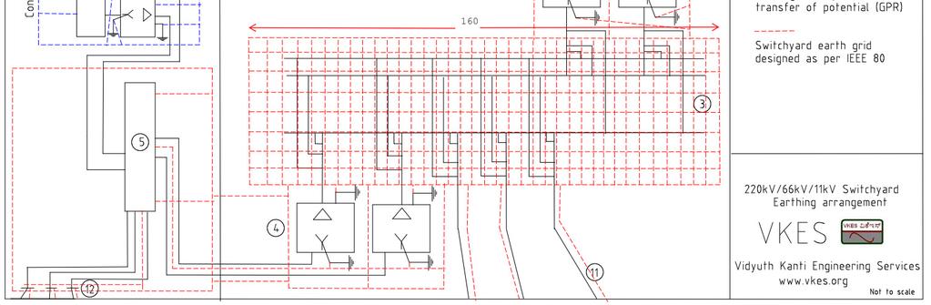
15 Step Voltage calculation E = = + + (1 0.5 ) = GPR- Ground potential rise When current flows through the earth, the potential increases at each and every location. Earth is a network of RLC circuit, when current flows through this three dimensional network voltage rises. When a person is standing both his foot experiences different potential, this difference is the step voltage. When a person is touching some object, his hand and foot experience different potential. The difference is the touch voltage. Bird sitting on a transmission line does not get a shock because its entire body is at same potential. In the same way GPR itself is not a problem but the different potential at different parts of body creates problem. GPR can be plotted using computer programs. It is not further studied here. However refer the below curve to get an idea how the GPR distribution appears. Transferred potential During fault, the fault current flows through the earth grid and this leads to a ground potential rise (GPR). All metal objects which are connected to the substation earth grid will experience an increase in the potential. Any non conducting metal connected to this earth grid experience a rise in its potential. If the equipment whose non conducting metal is located outside the substation, rise in potential is called transferred potential. Sometimes the transferred potential has led to serious damage of sensitive equipments and has caused fatalities. Hence this subject needs serious study. Transferred potential affecting 415V LV system: LV system Grounding inside the substation should not be interconnected with the substation grid as the substation GPR will lead to higher voltages in 415V earthing system. Power outlets if any in the switchyard should not be connected to switchyard earthing instead it should be connected to a separate 415V system earthing. Page 15 No 213, 13th Main RBI Layout JP Nagar 7th Phase, Bangalore , Mobile: , vkes@vkes.org, vkes765@gmail.com,
16 Page 16 No 213, 13th Main RBI Layout JP Nagar 7th Phase, Bangalore , Mobile: ,
17 Transferred potential affecting nearby by Rail Substation has rails installed during the initial commissioning stage. It is better to remove these rails as they may transfer the GPR to some distant location. Transferred potential affecting nearby Pipelines If any pipelines are passing near the substation ensure they are not bonded with the substation earth grid Transferred potential affecting Communication cable screening All cables, 11kV, 415V, or communication cable may have either an armour or a metal screen. The screen and armour will be earthed at the ends with help of cable glands earth tags. 415V cable armour and control cable screen earthing should not be connected to the substation earth grid. Control cable which originates at the switchyard marshalling kiosk should not be earthed at the switchyard end. Similarly the armour of any LV cable which provides power supply to the transformer fans should not be earthed at the switchyard end. Also Isolation transformer can be used to prevent GPR transfer. Analysis of the problems associated with GPR on communication cables, pipelines, rails etc is not part of this guideline. Detailed analysis will be done separately. What Causes GPR Refer below two figures for illustration of how GPR occurs.gpr mainly occurs due to that part of the fault current which flows through the Earth grid. In the below figure, the fault current in green colour is the one which enters the earth grid. This cause a GPR at the respective switchyard. GPR is not due to the fault current itself but it is due to a portion of the fault current which flows through the earth and enters the earth grid. Fault current which flows through the earth wire of transmission line, current which flows through metal pipelines, or rails or any other metallic infrastructure does not contribute to the GPR, instead these currents bring down the GPR. There will be no GPS when fault takes place on a bus connected to the secondary of a Transformer, where the Transformer neutral is connected to the substation grid. The fault current flows from the bus to the earth grid and back to the neutral. Fault current does not travel through the earth, hence it does not cause any GPR. Page 17 No 213, 13th Main RBI Layout JP Nagar 7th Phase, Bangalore , Mobile: , vkes@vkes.org, vkes765@gmail.com,
18 Page 18 No 213, 13th Main RBI Layout JP Nagar 7th Phase, Bangalore , Mobile: ,
19 In the above illustration an example of fault on 220kV Transmission line is taken. The fault of 12kA is shown by blue line. It is fed from a line and a 220kV/ 11kV Generator transformer. At the fault location the fault current divides itself and returns back to its source through the ground wire and through the earth. The current flowing through the earth cause GPR at the 220kV/11kV Transformer neutral earthing and at the 220kV substation earthing, which is connected to the 200kV transmission line. At the 220kV substation the fault current again takes two paths one is through the earthing conductor of the transmission line and the other through the earth. The division of the current can be determined using division factor which has been discussed in the previous paragraph.the fault occurring at some remote end can also create a GPR at the 220kV substation as the fault current flows back to the substation earth grid. GPR can be computed by, GPR= x Grid Resistance = ρ / (without ground rods) = (with ground rods and mutual ground resistance between grid and rods) = ln + is total length of grid conductors in m, A is area of grid in, a is radius of conductor in m are coefficients refer IEEE 80. = ln 1 + ( 1) is the length of each ground rod in m b is radius of the ground rod in m is the number of ground rods in area A = ln = 2h Page 19 No 213, 13th Main RBI Layout JP Nagar 7th Phase, Bangalore , Mobile: , vkes@vkes.org, vkes765@gmail.com,
20 Sample Calculations Sample calculation is performed for cases as mentioned below. Case 1: 40kA rms fault current without division factor and fault duration of 1sec Case 2: Fault within substation, with division factor, with decrement factor, duration 300msec Case 3: Fault on transmission line entering substation, duration 600msec Case 4: Fault on a 66kV bus of the substation Case 5: Fault at 11kV Switchgear Case 1: fault current without division factor and fault duration of 1sec 220kV Design fault level = 40kA rms (ref 1) Fault duration = 1 sec Resistivity of earth = 200 Ωm Height of gravel assumed as h = 100mm Resistivity of gravel, assume ρ = 2000 Ωm = 1.( )..( ) = 1 = 0.72 (.). =. =. ( ) =. ( x 2000 x 0.72 ) = V ( ) =. ( x 2000 x 0.72 ) = V Sizing of earthing grid =,. For copper annealed soft drawn =.... = x 3.46 =40 x 3.46 =138, OD=13.2mm Restrict maximum temperature to 250 deg C due to mechanical strength limitation. =.... For galvanised iron = x 5.53 =40 x 5.53 =221, OD=16.8mm =... = x 14 = 40 x 14 =709, OD=30mm Page 20 No 213, 13th Main RBI Layout JP Nagar 7th Phase, Bangalore , Mobile: , vkes@vkes.org, vkes765@gmail.com,
21 Both copper and iron have their own merits and demerits. It depends on owner s specification on which one has to be used. Copper has an advantage, it does not get corroded like iron but it is costly. But copper cannot be used where cathodic protection is used. If copper is used then joining of conductors should be done through bracing or exothermic joints. If galvanised iron is used welding needs to be employed. Further calculation will be proceeded with galvanised iron. Case 1: Fault inside substation with design fault current and duration 1sec Mesh Voltage D = Spacing between parallel conductors in m = 3 h = Depth of ground grid in m = 0.5; d = Diameter of grid conductor in m = 0.03 = total length of the conductor of horizontal grid in m = = peripheral length of the grid in m =580 = maximum length of grid in x direction in m =160; = maximum length of grid in y direction in m =130 A= Area of the grid in =20800 = maximum distance between any two points on the grid in m= 206 = 1 + (h = 1) = 1.22 = = 47.8 = =1 =. = 1 = = 1 = (Factor to take care of shapes of grid) =47.8 = n =7.72 = + (for grid with few ground rods) = = for few ground conductors and nil in periphery and corners () =1 for ground conductors throughout Page 21 No 213, 13th Main RBI Layout JP Nagar 7th Phase, Bangalore , Mobile: , vkes@vkes.org, vkes765@gmail.com,
22 = ln + () + ln () = + (.) ln (.) =0.17 E = =.. =758V E (758) >> (366.8) Lets add 500 ground rods of 3M each, = 1500, = 3 = = = = length of each ground conductor; = length of all ground conductor E = =.. = 648V There is not much change in the mesh voltage E (648) >> (366.8) Step Voltage = = 0.75 x x 1500 = = + + (1 0.5 ) = ( ) = E =.. = = 2742V E (2742) > (1119) The 40kA fault current considered in this calculation leads to a high GPR value. The fault duration considered as 1 sec may not be the case always as protective relays clear the fault much earlier. Due to these factors the step and touch voltage attained were not below the tolerable limits. In reality the fault current does not attain such a high value. Actual fault level can be calculated including future expansion of the substation. The division factor also needs to be considered. This is considered in the next case. Case 2: Fault inside a substation with fault current 20.5kA and duration 100ms Actual Fault current for fault inside substation was 20.5kA with 6 transmission lines. Fault on 220kV bus was highest, hence it considered. Considering future growth of two more bays, fault current contribution of each transmission line was assumed as 3.5KA. Total fault current can be considered as 28KA. For fault inside substation the Bus bar differential protection acts immediately. The Fault duration can be considered as 100ms. Page 22 No 213, 13th Main RBI Layout JP Nagar 7th Phase, Bangalore , Mobile: , vkes@vkes.org, vkes765@gmail.com,
23 =. =. ( ) =. ( x 2000 x 0.72 ) = 1160 V. ( ) =. ( x 2000 x 0.72 ) = 3536 V. Fault current distribution ( ) = tower resistance = 10Ω Ground wire: Galvanized stranded steel wire, Stranding and wire diameter 7/3.15mm, Total sectional area mm², approximate overall diameter 9.54 mm = AC resistance of ground conductor = 3.41 Ω/km at 20 deg C GMR= 2.21r= 2.21X1.575 =3.48mm= M = reactance of ground conductor = ln. = ln.. = 0.72 Ω/km = Ω /km = ln(93310 ρ) = Ω/km = = ( /3) + j( /3) =3.46+j1.24 = 3.67 Ω/km One span length of 220kV line= 320M =0.32kM of one span is = Ω = + = x 10 = for one transmission line for 6 present and 2 future transmission lines = 4.017/8 = = ρ / = / =0.629 = =... = Computation of with ground rods = ln + ( =4.5, =1 ) = 2h = 0.03 x 0.5 = = ln =0.475 Page 23 No 213, 13th Main RBI Layout JP Nagar 7th Phase, Bangalore , Mobile: , vkes@vkes.org, vkes765@gmail.com,
24 = = = ln 1 + ( 1) ln = ln = ln = = = =0.474 = =... = Decrement factor X/R for 220kV line 5.71 =DC offset time constant = = = Duration of fault in s =100 msec =0.1 = =, =, = = = x 28 x =15.68 ka 1.. = Mesh Voltage E = =.. =296.8V E (296.8) < (1160), However few round rods are added close to some equipment like surge arrestor, Transformer neutral, isolators etc. Consider 50 ground rods of 3M each, = 150, =3 = = E = =.. =291.87V E (291) < (1160) Page 24 No 213, 13th Main RBI Layout JP Nagar 7th Phase, Bangalore , Mobile: , vkes@vkes.org, vkes765@gmail.com,
25 Step Voltage = = 0.75 x x 150 = = + + (1 0.5 ) = ( ) = E =.. = = V E (1184) < (3536) In case 500 ground rods of 3m each are used as per previous example = = 0.75 x x 1500 = E =.. = = 1068 V E (1068) < (3536) Case 3: Fault on a Transmission line, with Fault current 10.6kA duration 600ms Fault on a Transmission line connected to the substation. Fault current was 10.6kA. The fault duration can be considered as 600 ms taking into account the tripping time of the transmission line relays. The fault current consist of two contribution, 6.1kA from one end of the line and 4.5kA from the substation under study. The GPR in the substation under study is due to a portion of 4.5kA which passes through the earthing grid. =. =. ( ) =. ( x 2000 x 0.72 ) = 473 V. ( ) =. ( x 2000 x 0.72 ) = V. Fault current distribution = for one transmission line =0.474 = = Page 25 No 213, 13th Main RBI Layout JP Nagar 7th Phase, Bangalore , Mobile: , vkes@vkes.org, vkes765@gmail.com,
26 Decrement factor X/R for 220kV line is 5.71, =DC offset time constant = = = Duration of fault in s =600 msec =0.6 = = =1.015 Grid Current =, =,, = = 0.894x 4.5x =4.084 ka Mesh Voltage E = =.. =77.3V E (77.3) < (473), Step Voltage E =.. = = 308 V E (308) < (1443) Case 4: Fault on a 66kV bus of the substation. The Fault current is 14.58kA lesser than 20.5kA fault current at 220kV. Hence this case need not be studied. Case 5: Fault at 11kV Switchgear. The Fault current is 19kA and fault duration will be high in order to coordinate with outgoing radial distribution feeders. But step and touch voltage calculation is not applicable for this fault. The fault current flows into the earth grid and enters the neutral of the transformer through the metallic path. Hence Ground potential rise caused by the fault will not be much. Page 26 No 213, 13th Main RBI Layout JP Nagar 7th Phase, Bangalore , Mobile: , vkes@vkes.org, vkes765@gmail.com,
27 Reference: IEEE 80: guide for safety in AC substation grounding IEEE Transactions on Power Apparatus and Systems, Vol. PAS-98, pp , May Ground fault current distribution in substation, towers and ground wire IEEE Transactions on Power Apparatus and Systems, Vol. PAS-86, No. 10 October 1967, Analysis of Transmission Tower Potentials, by Janos Endrenyl CEA Transmission planning criteria KPTCL Tech Spec for Line survey HVPNL Tech Spec T&D Handbook Page 27 No 213, 13th Main RBI Layout JP Nagar 7th Phase, Bangalore , Mobile: ,
28
29
30 ABOUT VKES is a Bangalore based Startup by Paneendra Kumar BL. Paneendra kumar BL is a Charted Engineer (UK), Senior member IEEE (USA), Associate member institute of engineers India. Has done Masters in power system from IIT delhi and BE Electrical from RV college of engineering Bangalore. He has 15 years experience in Electrical Engineering of Industrial power distribution, Power plants, Oil and gas, Transmission and Distribution and Power quality. He has published paper in IEEE
31
Worked Example for the Calculation of Earthing Current and Electric Shock Hazard Potential Difference in a Rod and Grid Earthing System
 Appendix H Worked Example for the Calculation of Earthing Current and Electric Shock Hazard Potential Difference in a Rod and Grid Earthing System H.1 WORKED EXAMPLE A 33 kv overhead line terminates at
DEPARTMENT OF ELECTRICAL AND ELECTRONICS ENGINEERING QUESTION BANK
 DEPARTMENT OF ELECTRICAL AND ELECTRONICS ENGINEERING QUESTION BANK SUBJECT CODE & NAME: EE 2303 - TRANSMISSION & DISTRIBUTION YEAR / SEM: III/V UNIT-I TRANSMISSION SYSTEM INTRODUCTION PART-A 1. What is
Engineering Recommendation EREC S34 Issue 2, November A guide for assessing the rise of earth potential at electrical installations
 PRODUCED BY THE OPERATIONS DIRECTORATE OF ENERGY NETWORKS ASSOCIATION Engineering Recommendation EREC S34 Issue 2, November 2018 A guide for assessing the rise of earth potential at electrical installations
Influence of Grounding Material s Property on the Impulse Grounding Resistance of Grounding Grids
 International Conference on Electrical, Electronics and Mechatronics (ICEEM 2015) Influence of Grounding Material s Property on the Impulse Grounding Resistance of Grounding Grids Leishi Xiao1, Qian Li1
The objective of a grounding system are: 1. To provide safety to personnel during normal and fault conditions by limiting step and touch potential.
 GROUNDING SYSTEMS Part 1 Professor Ahdab Elmorshedy 1 Reference: High Voltage Engineering Theory and Practice, Text Book, Marcel Dekker Inc. NY, USA, 2000. Mazen Abdel-Salam, Hussein Anis, Ahdab Elmorshedy,
Fault Calculation Methods
 ELEC9713 Industrial and Commercial Power Systems Fault Calculation Methods There are two major problems that can occur in electrical systems: these are open circuits and short circuits. Of the two, the
Three Core XLPE/LSF/SWA/LSF Power Cable
 1 Three Core XLPE/LSF/SWA/LSF Power Cable./ kv Application LSF armoured power cable for use in fixed installations. Especially for use in areas where fire would create dense smoke and toxic fumes causing
SUPPLY, ERECTION & COMMISSIONING OF 2 X 3.15 MVA 33/11KV SUB-STATION at Khuntlipalli,Bargarh ( PACKAGE - B )
") SUPPLY, ERECTION & COMMISSIONING OF 2 X 3.15 MVA 33/11KV SUB-STATION at Khuntlipalli,Bargarh ( PACKAGE - B ) Sl. 1 2 Description of Work Supply,Erection & Commissioning of 2 x 3.15 MVA, New 33/11 KV Primary
SUPPLY, ERECTION & COMMISSIONING OF 2 X 3.15 MVA 33/11KV SUB-STATION at Khuntlipalli,Bargarh ( PACKAGE - B ) Sl. 1 2 Description of Work Supply,Erection & Commissioning of 2 x 3.15 MVA, New 33/11 KV Primary
Analysis of Very Fast Transients in EHV Gas Insulated Substations
 Analysis of Very Fast Transients in EHV Gas Insulated Substations A.Raghu Ram, k. Santhosh Kumar raghuram_a@yahoo.com,ksanthosheee@gmail.com Abstract: Gas insulated switchgear (GIS) has been in operation
Single Core XLPE/LSF/AWA/LSF Power Cable
 Single Core XLPE/LSF/AWA/LSF Power Cable 00/00V and 100/00V Application LSF insulated, armoured and sheathed, single core power cable for use in fixed installations. Especially for use in areas where fire
16 Appendix 16 Electrical Research Association Report
 Guide to the Wiring Regulations 16 Appendix 16 Electrical Research Association Report (ERA) report on armoured cables with external CPCs The attached report was commissioned by the ECA and is copyright
COPPER FOR BUSBARS CHAPTER 4: SHORT-CIRCUIT EFFECTS
 European Copper Institute COPPER FOR BUSBARS CHAPTER 4: SHORT-CIRCUIT EFFECTS David Chapman August 2011 ECI Available from www.leonardo-energy.org Document Issue Control Sheet Document Title: Publication
1. Explain the various methods of methods of grounding. In power system, grounding or earthing means connecting frame of electrical equipment (non-cur
 1. Explain the various methods of methods of grounding. In power system, grounding or earthing means connecting frame of electrical equipment (non-current carrying part) or some electrical part of the
Risk indexes for studying interconnected earthing systems inside MV networks
 Risk Analysis V: Simulation and Hazard Mitigation 67 Risk indexes for studying interconnected earthing systems inside MV networks A. Campoccia & G. Zizzo Department of Electrical, Electronic and Telecommunications
Electricity. What is electricity?
 Words attract = pull towards an object back and forth = to go in one direction and then in the other balanced = the same as stable carbon = a chemical material that is in coal or petrol. It is in its purest
Earth Resistance and Calculation of Earthing
 University of Ljubljana Faculty of Electrical Engineering Earth Resistance and Calculation of Earthing Seminar paper at subject Distribution and Industrial Systems Student: Mentor: Prof. dr. Grega Bizjak
BETA Protecting. Low-Voltage Fuse Systems. LV HRC fuse links. 3/36 Siemens ET B1 2008
 LV HRC fuse links Overview LV HRC fuses are used for installation systems in non-residential, commercial and industrial buildings as well as in switchboards of power supply companies. They therefore protect
Modeling of Transmission Line and Substation for Insulation Coordination Studies
 TRAINING DUBROVNIK, CROATIA - APRIL, 27-29 2009 SIMULATION & ANALYSIS OF POWER SYSTEM TRANSIENTS WITH EMTP-RV Modeling of Transmission Line and Substation for Insulation Coordination Studies Prof. Ivo
VX25 Enclosure System. Technical documentation PE conductor connection, current carrying capacity
 VX Enclosure System Technical documentation PE conductor connection, current carrying capacity Enclosure system VX Contents Contents. General remarks. Introduction. Notes on the design of the earthing
INTERNATIONAL JOURNAL OF ELECTRICAL ENGINEERING & TECHNOLOGY (IJEET)
") INTERNATIONAL JOURNAL OF ELECTRICAL ENGINEERING & TECHNOLOGY (IJEET) International Journal of Electrical Engineering and Technology (IJEET), ISSN 976 6545(Print), ISSN 976 6553(Online) Volume 3, Issue
INTERNATIONAL JOURNAL OF ELECTRICAL ENGINEERING & TECHNOLOGY (IJEET) International Journal of Electrical Engineering and Technology (IJEET), ISSN 976 6545(Print), ISSN 976 6553(Online) Volume 3, Issue
Alternating Current (AC): Alternating Current is electric current that reverses directions at regular intervals.
: Alternating Current is electric current that reverses directions at regular intervals.") Glossary Alternating Current (AC): Alternating Current is electric current that reverses directions at regular intervals. American National Standards Institute (ANSI): American National Standards Institute
Glossary Alternating Current (AC): Alternating Current is electric current that reverses directions at regular intervals. American National Standards Institute (ANSI): American National Standards Institute
Proximity effect on bare buried conductors connecting together MV/LV substations earth electrodes
 Proceedings of the 6 IASME/WSEAS International onference on Energy & Environmental Systems, halkida, Greece, May 8-, 6 (pp7-) Proximity effect on bare buried conductors connecting together MV/LV s earth
University of Moratuwa, Sri Lanka. EE3231: Design of Electrical Installation
 University of Moratuwa, Sri Lanka B.Sc. Engineering Level 4 Semester 1 Examination EE3231: Design of Electrical Installation Time allowed: 2 Hours January 2010 Additional Material: Not required INSTRUCTIONS
Figure 1-44: 4-Wire Wye PT Configurations
 Principles and Practice ii) PT onnection There are two most common PT combinations on three-phase, three-wire systems as shown in Figure 1-43. The vector diagrams are identical between PT configurations
Electrical, Electronic and Computer Engineering ENEL4HB - High Voltage 2
 Electrical, Electronic and Computer Engineering ENEL4HB - High oltage 2 Main Examination October 2016 Instructions Answer all questions, show all working and include all necessary comments (it is your
NYY-J/-o 34 NYCWY 36 NYCY 37 NAYY 38
 NYY-J/-o 34 NYCWY 36 NYCY 37 NAYY 38 NYY-J/-O Energy and control cable acc. to DIN VDE 0276 and HD 603 Application Indoor and outdoor installation, laying in ducts and underground, for power stations,
VALIDATION OF AN INTEGRATED METHODOLOGY FOR DESIGN OF GROUNDING SYSTEMS THROUGH FIELD MEASUREMENTS
 VALIDATION OF AN INTEGRATED METHODOLOGY FOR DESIGN OF GROUNDING SYSTEMS THROUGH FIELD MEASUREMENTS Carlos CARDOSO Luís ROCHA Andreia LEIRIA Pedro TEIXEIRA EDP Labelec - Portugal EDP Labelec - Portugal
Power system conductor volume calculation
 Power system conductor volume calculation Dr Audih alfaoury T&D power systems 2017-1018 Electrical Energy Engineering Department Dr Audih alfaoury 1 The transmission of electric power is carried at high
Electrical, Electronic and Computer Engineering ENEL4HB - High Voltage 2
 Electrical, Electronic and Computer Engineering ENEL4HB - High Voltage 2 Main Examination October 2015 Instructions Answer all questions and show all working. Time allowed = 2 hours Full marks = 100 Question
Transient analysis of the behaviour of grounding systems consisted by driven rods
 Transient analysis of the behaviour of grounding systems consisted by driven rods I.F. GONOS M.K. ANTONIOU I.A. STATHOPULOS F.V. TOPALIS Department of Electrical and Computer Engineering, High Voltage
Modeling and Simulation of Air Insulated and Gas Insulated Substations
 International Journal of Electrical Engineering. ISSN 0974-2158 Volume 11, Number 2 (2018), pp. 177-187 International Research Publication House http://www.irphouse.com Modeling and Simulation of Air Insulated
Collation Studies of Sequence Impedances for Underground Cables with Different Layouts
 Collation Studies of Sequence Impedances for Underground Cables with Different Layouts M.Ramya 1, G.Radhika 2, Poonam Upadhyay 3 1 Department of EEE, VNRVJIET, Hyderabad, India 2 Department of EEE, Sr.Assistant
Harmonic Modeling of Networks
 Harmonic Modeling of Networks Thomas H. Ortmeyer ECE Dept. Clarkson University Potsdam, NY 13699-5720 M. Fayyaz Akram Dept. of Elec. Eng. Univ. of Engineering and Technology Lahore, Pakistan Takashi Hiyama
Power System Engineering Prof. Debrapriya Das Department of Electrical Engineering Indian Institute of Technology, Kharagpur
 Power System Engineering Prof. Debrapriya Das Department of Electrical Engineering Indian Institute of Technology, Kharagpur Lecture - 01 Overhead Line Insulators So, welcome to this another course that
PARTICLE TRAJECTORIES IN A THREE PHASE COMMON ENCLOSURE GAS INSULATED BUSDUCT WITH MONTE CARLO TECHNIQUE
 PARTICLE TRAJECTORIES IN A THREE PHASE COMMON ENCLOSURE GAS INSULATED BUSDUCT WITH MONTE CARLO TECHNIQUE M. Venu Gopala Rao 1, J. Amarnath 2 and S. Kamakshaiah 3 1 QIS College of Engineering and Technology,
High Voltage Capacitors Designed to Avoid Catastrophic Failure Modes
 GENERAL ATOMICS ENERGY PRODUCTS Engineering Bulletin High Voltage Capacitors Designed to Avoid Catastrophic Failure Modes F. W. MacDougall G. L. McKee, J.B. Ennis, R.A. Cooper Maxwell Energy Products,
F F FAULT CURRENT Prospective. 1. Introduction. 2. Types of fault conditions
 FAULT CURRENT F F13-13 FAULT CURRENT - Contents 1. Introduction 2. Types of fault conditions 3 fault current must be determined 3.1 Purposes for which of prospective fault current magnitudes are used 3.2
SWITCHGEAR: design concepts, testing, standards and safety of persons and installations
 MEDIUM AND LOW VOLTAGE Part 1 SWITCHGEAR: design concepts, testing, standards and safety of persons and installations Presented by: Sergio Feitoza Costa COGNITOR Consultancy, R&D & training Ltd www.cognitor.com.br
Effective Design of Large Grounding Systems
 Effective Design of Large Grounding Systems Lorentzou M.I. Hatziargyriou N.D. National Technical University of Athens Department of Electrical Engineering 9 Heroon Politechniou, Zografou Campus, Athens,
DIRECT STROKE LIGHTNING PROTECTION DESIGN
 International Journal of Research in Engineering and Applied Sciences(IJREAS) Available online at http://euroasiapub.org/journals.php Vol. 7 Issue 1,January7, pp. 1~12cv ISSN (O): 2249-3905, ISSN(P) :
POWER SEMICONDUCTOR BASED ELECTRIC DRIVES
 POWER SEMICONDUCT BASED ELECTRIC DRIVES [Time: 3 Hrs] [Max. Marks: 80] Instructions: Solve any six questions from Q.No (1 or 2), Q.No (3 or 4), Q.No (5 or 6), Q.No (7 or 8), Q.No (9 or 10), Q.No (11 or
Electrical Power Cables Part 2 Cable Rating Calculations
 ELEC971 High Voltage Systems Electrical Power Cables Part Cable Rating Calculations The calculation of cable ratings is a very complex determination because of the large number of interacting characteristics
ADMISSION TEST INDUSTRIAL AUTOMATION ENGINEERING
 UNIVERSITÀ DEGLI STUDI DI PAVIA ADMISSION TEST INDUSTRIAL AUTOMATION ENGINEERING September 26, 2016 The candidates are required to answer the following multiple choice test which includes 30 questions;
THE DIMENSIONING OF ELECTRICAL CONDUCTORS FOR USE IN "PANEL BOARDS" ADDRESSED TO HAZARDOUS AREAS - PART THREE
 July 04 THE DIMENSIONING OF ELECTRICAL CONDUCTORS FOR USE IN "PANEL BOARDS" ADDRESSED TO HAZARDOUS AREAS - PART THREE In this third part. we want to speak about how important is the correct sizing of the
Instruction. Vacuum Circuit Breaker Operator Module. Type 3AH 4.16kV to 38kV. Power Transmission & Distribution
 Instruction 0001-22-2--00 Vacuum Circuit Breaker Operator Module Type 3AH 4.16kV to 38kV Power Transmission & Distribution Hazardous voltages and high-speed moving parts. Will cause death, serious injury
Superconducting Fault Current Limiters
 Superconducting Fault Current Limiters First Friday Club 1 st April 2011 Gerhard Novak UK Technical Manager Joachim Bock Managing Director, Nexans Superconductors 1 Smart Grid Solutions 2 Fault current
Lightning overvoltages and compliance with the ITI (CBEMA) curve
 curve") Lightning overvoltages and compliance with the ITI (CBEMA) curve Alessandro Manunza M2EC M2EC, Italy Via Coppelli 15 20037, Paderno Dugnano, Italy m2ec@manunza.com Abstract The analysis of Insulation Coordination
Lightning overvoltages and compliance with the ITI (CBEMA) curve Alessandro Manunza M2EC M2EC, Italy Via Coppelli 15 20037, Paderno Dugnano, Italy m2ec@manunza.com Abstract The analysis of Insulation Coordination
SSC-JE EE POWER SYSTEMS: GENERATION, TRANSMISSION & DISTRIBUTION SSC-JE STAFF SELECTION COMMISSION ELECTRICAL ENGINEERING STUDY MATERIAL
 1 SSC-JE STAFF SELECTION COMMISSION ELECTRICAL ENGINEERING STUDY MATERIAL Power Systems: Generation, Transmission and Distribution Power Systems: Generation, Transmission and Distribution Power Systems:
Electroscope Used to are transferred to the and Foil becomes and
 Electricity Notes Chapter 17 Section 1: Electric Charge and Forces Electric charge is a variety of independent all with one single name. Electricity is related to, and both (-) and (+) carry a charge.
Fatima Michael College of Engineering & Technology
 ANNA UNIVERSITY AFFILIATED COLLEGES BE EEE SEMESTER VI EE2353 - HIGH VOLTAGE ENGINEERING UNIT IOVER VOLTAGES IN ELECTRICAL POWER SYSTEMS 1. What is surge arrester? 2. Name the sources of switching surges.
Hydra Fault Current Limiting HTS Cable to be Installed in the Consolidated Edison Grid
 Hydra Fault Current Limiting HTS Cable to be Installed in the Consolidated Edison Grid J. McCall, J. Yuan, D. Folts, N. Henderson, American Superconductor D. Knoll, Southwire M. Gouge, R. Duckworth, J.
Mitigation and Analysis of Very Fast Transient over Voltages (VFTOs) in 765/245kV Gas Insulated Substation (GIS) by Wavelet Transforms
 in 765/245kV Gas Insulated Substation (GIS) by Wavelet Transforms") AASCIT Communications Volume 5, Issue 3 ISSN: 2375-383 Mitigation and Analysis of Very Fast Transient over Voltages (VFTOs) in 765/245kV Gas Insulated Substation (GIS) by Wavelet Transforms Krishaniah
AASCIT Communications Volume 5, Issue 3 ISSN: 2375-383 Mitigation and Analysis of Very Fast Transient over Voltages (VFTOs) in 765/245kV Gas Insulated Substation (GIS) by Wavelet Transforms Krishaniah
7.9.4 Static Electricity
 7.9.4 Static Electricity 71 minutes 79 marks Page 1 of 19 Q1. The diagram shows a student after rubbing a balloon on his hair. The balloon and hair have become charged. (a) Draw a ring around the correct
For the electronic measurement of current: DC, AC, pulsed..., with galvanic separation between the primary and the secondary circuit.
 Current Transducer HO-NP/SP33 series I PN = 8, 15, 25 A Ref: HO 8-NP/SP33, HO 15-NP/SP33, HO 25-NP/SP33 For the electronic measurement of current: DC, AC, pulsed..., with galvanic separation between the
Faults on Electrical System. A Research
 Faults on Electrical System A Research Presented to Electrical Engineering School of Engineering and Architecture Mindanao University of Science and Technology Cagayan de Oro City In partial fulfilment
r r 4πε 0 r From the relations between measured or known electrical quantities, material properties and apparatus dimensions you can determine ε 0.
 8.0T Fall 001 Electrostatic Force 1 Introduction In this experiment you ll investigate aspects of the electrostatic force. This force has such varied roles as making currents flow in wires, holding atoms
5SJ4...-.HG Circuit Breakers to IEC and UL 489
 Siemens AG 009 5SJ...-.HG Circuit Breakers to IEC and UL 89 BETA Low-Voltage Circuit Protection Compliance with industry standards is a must in today's manufacturing environment. Worldwide acceptance is
Evaluation of the risk of failure due to switching overvoltages of a phase to phase insulation
 Evaluation of the risk of failure due to switching overvoltages of a phase to phase insulation A. Xemard, J. Michaud, A. Guerrier, I. Uglesic, G. Levacic, M. Mesic Abstract-- The upgrade of an overhead
Northwest Hydro Tech Session_2017
 STEP POTENTIAL FROM AN OPERATORS VIEW Presented by Fred WAC 296-45-005 ELECTRICAL WORKERS SAFETY RULES-FOREWORD. This chapter is not intended to be a complete job description nor is it expected that the
Parametric Study of Losses in Cross-Bonded Cables: Conductors Transposed Versus Conductors Nontransposed
 IEEE TRANSACTIONS ON POWER DELIVERY, VOL 28, NO 4, OCTOBER 2013 2273 Parametric Study of Losses in Cross-Bonded Cables: Conductors Transposed Versus Conductors Nontransposed Prajakta Moghe and Francisco
Electrostatics. Thomas Jefferson National Accelerator Facility - Office of Science Education
 Electrostatics Electrostatics What happens to Different objects when they are electrically charged? 1. In this experiment, a device called a Van de Graaff generator will be used to place extra electrons
EPRI Lightning Protection Design Workstation
 EPRI Lightning Protection Design Workstation Tom McDermott Electrotek Concepts, Inc. 2000 Winter Power Meeting LPDW v5 Components Includes 1988-97 flash data from the National Lightning Detection Network
EARTH SURFACE POTENTIALS AND GPR OF SUBSTATION GROUNDING
 EARTH SURFACE POTENTIALS AND GPR OF SUBSTATION GROUNDING Ossama Gouda Ghada Amer Hana Ibrahim Faculty of Eng., Cairo Univ. Egypt HIT, Benha Univ. Egypt N.E.C.C - Egypt d_gouda@yahoo.com dr_ghada11@hotmail.com
*We studied the following types of En.: Potential and kinetic EX of potential is Chemical EX of kinetic is Temperature Another Ex of kinetic En is:
 *We studied the following types of En.: Potential and kinetic EX of potential is Chemical EX of kinetic is Temperature Another Ex of kinetic En is: *Electrical Energy also called Electricity - ( the result
4.2.1 Current, potential difference and resistance
 4.2 Electricity Electric charge is a fundamental property of matter everywhere. Understanding the difference in the microstructure of conductors, semiconductors and insulators makes it possible to design
Technical Challenge of Lightning Protection for Wind Power Generation
 Technical Challenge of Lightning Protection for Wind Power Generation 18 th November,2008 Takayuki Nakamoto,Hiroshi Morita Kinden Corporation Contents 1.Situation of wind power generation in the worldwide
For the electronic measurement of current: DC, AC, pulsed..., with galvanic separation between the primary and the secondary circuit.
 Current Transducer HO-NSM series I PN = 8, 15, 25 A Ref: HO 8-NSM, HO 15-NSM, HO 25-NSM For the electronic measurement of current: DC, AC, pulsed..., with galvanic separation between the primary and the
Effects of Capacitor Bank Installation in a Medium Voltage (MV) Substation
 Substation") Effects of Capacitor Bank Installation in a Medium Voltage (MV) Substation Adesina, Lambe Mutalub Department of Engineering & Standardization, Eko Electricity Distribution Plc, 24/25, Marina, Lagos Island,
Effects of Capacitor Bank Installation in a Medium Voltage (MV) Substation Adesina, Lambe Mutalub Department of Engineering & Standardization, Eko Electricity Distribution Plc, 24/25, Marina, Lagos Island,
Electromotive Force. The electromotive force (emf), ε, of a battery is the maximum possible voltage that the battery can provide between its terminals
, ε, of a battery is the maximum possible voltage that the battery can provide between its terminals") Direct Current When the current in a circuit has a constant magnitude and direction, the current is called direct current Because the potential difference between the terminals of a battery is constant,
Direct Current When the current in a circuit has a constant magnitude and direction, the current is called direct current Because the potential difference between the terminals of a battery is constant,
CONTRIBUTION TO CALCULATING THE IMPEDANCE OF GROUNDING ELECTRODES USING CIRCUIT EQUIVALENTS. Andrijana Kuhar, Leonid Grcev
 FACTA UNIVERSITATIS Series: Electronics and Energetics Vol. 29, N o 4, December 2016, pp. 721-732 DOI: 10.2298/FUEE1604721K CONTRIBUTION TO CALCULATING THE IMPEDANCE OF GROUNDING ELECTRODES USING CIRCUIT
Module 3 : Sequence Components and Fault Analysis
 Module 3 : Sequence Components and Fault Analysis Lecture 12 : Sequence Modeling of Power Apparatus Objectives In this lecture we will discuss Per unit calculation and its advantages. Modeling aspects
Optimal Design of Earthing System Base on Genetic Algorithm.
 Optimal Design of Earthing System Base on Genetic Algorithm Mohamed Ahmed Mehanna 1 and Mokhtar Hussien Abdullah 2 1 Electrical Engineering Department, Faculty of Engineering, Al-Azhar University, Nasr-City,
Digital Current Transducer HO-SW series I P N = A. Ref: HO 100-SW; HO 150-SW; HO 200-SW; HO 250-SW
 Digital Current Transducer HO-SW series I P N = 100... 250 A Ref: HO 100-SW; HO 150-SW; HO 200-SW; HO 250-SW Bitstream output from on onboard Sigma Delta modulator. For the electronic measurement of current:
The equation which links current, potential difference and resistance is:
 An electrical circuit is shown in the figure below. The current in the circuit is direct current. What is meant by direct current? Tick one box. Current that continuously changes direction. Current that
HIGH SCHOOL SCIENCE. Physical Science 7: Electricity & Magnetism
 HIGH SCHOOL SCIENCE Physical Science 7: Electricity & Magnetism WILLMAR PUBLIC SCHOOL 2013-2014 EDITION CHAPTER 7 Electricity & Magnatism In this chapter you will: 1. Analyze factors that affect the strength
CHAPTER 3 CONVENTIONAL DESIGN SOLUTIONS
 31 CHAPTER 3 CONVENTIONAL DESIGN SOLUTIONS 3.1 CONVENTIONAL DESIGN Conventional design is a trial and error method. It makes use of empirical relations, approximations and assumptions. (Say 1958) A method
Outline of College Physics OpenStax Book
 Outline of College Physics OpenStax Book Taken from the online version of the book Dec. 27, 2017 18. Electric Charge and Electric Field 18.1. Static Electricity and Charge: Conservation of Charge Define
Chapter 28. Direct Current Circuits
 Chapter 28 Direct Current Circuits Circuit Analysis Simple electric circuits may contain batteries, resistors, and capacitors in various combinations. For some circuits, analysis may consist of combining
f Static Electricity:
 ELECTRICITV VOCflB WORDS Electricity: f Static Electricity: Current Electricity: Electron: Neutron: Proton: Attraction: Repulsion: / ^ Source: Conductor: Insulator: Load: Switch: Series Circuit: Parallel
66kV & 220kV Substation Protection From Lightning by Fixed Angle, Rolling Sphere and Early Streamer Method
 RESEARCH ARTICLE OPEN ACCESS 66kV & 220kV Substation Protection From Lightning by Fixed Angle, Rolling Sphere and Early Streamer Method Pruthak C. Chauhan. 1, Rinkesh S. Kansara 2, Mukesh P. Patel 3, Anil
TeSys circuit-breakers
 Presentation Thermal-magnetic motor circuit-breakers types GV2, GV and GV7 GV2-ME, GV2-P, GV-ME and GV7-R motor circuit-breakers are -pole thermal-magnetic circuit-breakers specifically designed for the
For the electronic measurement of current: DC, AC, pulsed..., with galvanic separation between the primary and the secondary circuit.
 Current Transducer HO-NP series I P N = 4, 6, 12, 15 A Ref: HO 4-NP, HO 6-NP, HO 12-NP, HO 15-NP For the electronic measurement of current: DC, AC, pulsed..., with galvanic separation between the primary
4.2.1 Current, potential difference and resistance Standard circuit diagram symbols. Content. Key opportunities for skills development WS 1.
 4.2 Electricity Electric charge is a fundamental property of matter everywhere. Understanding the difference in the microstructure of conductors, semiconductors and insulators makes it possible to design
G E F D. 1. The diagram shows an electronic circuit. Write down the names of the components in the list below. A =... B =... C =... D =...
 1. The diagram shows an electronic circuit. + 9 V G E A F D B C 0 V (a) Write down the names of the components in the list below. A =... B =... C =... D =... E, F and G =... (5) watford grammar school
Grid Issues and Challenges Addressed by High Temperature Superconductor (HTS) Technology
 Technology") CIGRÉ US National Committee 21, rue d Artois, F-75008 PARIS Grid of the Future Symposium http : //www.cigre.org Kansas City, October 28-30, 2012 Grid Issues and Challenges Addressed by High Temperature
CIGRÉ US National Committee 21, rue d Artois, F-75008 PARIS Grid of the Future Symposium http : //www.cigre.org Kansas City, October 28-30, 2012 Grid Issues and Challenges Addressed by High Temperature
Electricity MR. BANKS 8 TH GRADE SCIENCE
 Electricity MR. BANKS 8 TH GRADE SCIENCE Electric charges Atoms and molecules can have electrical charges. These are caused by electrons and protons. Electrons are negatively charged. Protons are positively
ELECTRICITY. Chapter ELECTRIC CHARGE & FORCE
 ELECTRICITY Chapter 17 17.1 ELECTRIC CHARGE & FORCE Essential Questions: What are the different kinds of electric charge? How do materials become charged when rubbed together? What force is responsible
allow ii anomalous point at 60, 2350; 1 iii LOBF; should go through 60, 1750 approx no obvious abrupt changes of gradient
 a Answer Notes Marks D b i Any two ideas from: MP. it acts as water bath; allow MP. gives more gradual heating or cooling OR gives (easier/better) control of temperature; MP3. protects the thermistor against
25 (μh/ω) for sizes 0,5 / 0,75 / 1 mm2 Maximum L/R Ratio:
 for sizes 0,5 / 0,75 / 1 mm2 Maximum L/R Ratio:") Based on: EN 50288-7 Nominal voltage: 500V The colours may differ from the actual colours. 1. Construction: 1. : Stranded annealed bare copper. Class 2 in accordance with IEC 60228. 2. : Fire barrier:
Based on: EN 50288-7 Nominal voltage: 500V The colours may differ from the actual colours. 1. Construction: 1. : Stranded annealed bare copper. Class 2 in accordance with IEC 60228. 2. : Fire barrier:
765kV Transmission Line for Capacity Enhancement
 International Conference on Multidisciplinary Research & Practice P a g e 200 765kV Transmission Line for Capacity Enhancement Abhilash A. Netake #, P. K. Katti * # M. Tech-II(Electrical), *Professor Electrical
Electrodynamic Forces Affecting Lightning Protection System Components and Structures
 2014 International Conference on Lightning Protection (ICLP), Shanghai, China Electrodynamic Forces Affecting Lightning Protection System Components and Structures Volodymyr Shostak, Mikhailo Sypchenko
FAZ tripping characteristics at 30 C: B, C, D to IEC/EN FAZ tripping characteristics at 30 C: R to IEC/EN
 FAZ, AZ High-Capacity Tripping Characteristics Moeller HPL011-001/00 1/07 FAZ tripping characteristics at 0 C: B, C, D to IEC/EN 0 9 FAZ tripping characteristics at 0 C: R to IEC/EN 0 97 t [s] 700 00 100
Superconducting Fault Current Limiters
 Superconducting Fault Current Limiters Prof. Dr.-Ing. Mathias Noe, Karlsruhe Institute of Technology Institute for Technical Physics EASITrain Summer School,, September 3rd-7th 2018, Vienna KIT-ENERGY
Overhead lines. 110 kv wood tower with guy wires
 Overhead lines a) ja b) 0 kv wood poles c) free standing 0 kv metal tower with I-strings d) free standing 440 kv metal tower with V-strings e) 400 kv metal tower with guy wires 0 kv wood tower with guy
11. ELECTRIC CURRENT. Questions and Answers between the forces F e and F c. 3. Write the difference between potential difference and emf. A.
 CLSS-10 1. Explain how electron flow causes electric current with Lorentz-Drude theory of electrons?. Drude and Lorentz, proposed that conductors like metals contain a large number of free electrons while
The Lightning Study of Overhead Transmission Lines
 IOSR Journal of Electrical and Electronics Engineering (IOSR-JEEE) e-issn: 2278-1676,p-ISSN: 232-3331, Volume 1, Issue 5 Ver. II (Sep Oct. 215), PP 69-75 www.iosrjournals.org The Lightning Study of Overhead
1 Fig. 3.1 shows the variation of the magnetic flux linkage with time t for a small generator. magnetic. flux linkage / Wb-turns 1.
 1 Fig. 3.1 shows the variation of the magnetic flux linkage with time t for a small generator. 2 magnetic 1 flux linkage / 0 10 2 Wb-turns 1 2 5 10 15 t / 10 3 s Fig. 3.1 The generator has a flat coil
Lightning Insulation Coordination Study
 Lightning Insulation Coordination Study Presenter: Nguyen Dong Hai Le Pacific 1 Presentation Outline Introduction Network Components Model Stroke Current Model Case Studies and esults Conclusions 1 Introduction
Standard circuit diagram symbols Content Key opportunities for skills development
 4.2 Electricity Electric charge is a fundamental property of matter everywhere. Understanding the difference in the microstructure of conductors, semiconductors and insulators makes it possible to design
UNIVERSITY OF CAMBRIDGE INTERNATIONAL EXAMINATIONS General Certificate of Education Ordinary Level
 UNIVERSITY OF CAMBRIDGE INTERNATIONAL EXAMINATIONS General Certificate of Education Ordinary Level *7018231122* PHYSICS 5054/22 Paper 2 Theory October/November 2010 1 hour 45 minutes Candidates answer