Masonry. Masonry - mostly vertical members. Columns are resistant to vertical actions but sensitive to horizontal actions.
|
|
|
- Heather Pearson
- 5 years ago
- Views:
Transcription


 action")
1 Masonry Masonry - mostly vertical members Columns are resistant to vertical actions but sensitive to horizontal actions. Walls are resistant to vertical and longitudinal actions but sensitive to transverse actions. Vertical action Longitu dinal action Transverse (cross - wise) action

2 Masonry as a structural material Components - Masonry units EN 720, strengtht f b = δ f u, - δ the coefficient of units dimensions, -f u the mean of unit strength, - Mortal EN , e.g. M10, f m = 10 MPa cement: lime: sand (commonly) 1:1:5 Masonry plain masonry - normal mortal - thin joints - light mortal reinforced masonry prestressed masonry Compressive zones in plain concrtee and masonry
 natural materials, later production of bricks from various plastic materials 9000 years ago")
3 Masonry historical notes Bricks the oldest artificial construction material Middle East, Irán lack of natural stones At the beginning shaping (forming) natural materials, later production of bricks from various plastic materials 9000 years ago Manufacturing of bicks
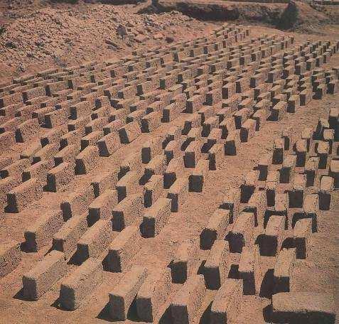

4 Draying technology on a sun


5 Mesopotamia Pergamon muzeum Samára 9. století


6 Samarkand - Registan Nymburk
7 Applications Widely used material economy Easy detailing Short construction interval Reduction of subcontructors Human size Broad spectrum of units Resistance to natural influences Minimum maintenance Excelent thermal properties Small unites Easy forming Gret opportunities to architects Local raw materials Construction periods limited EN Characteristic strength Masonry strength of plain masonry: f k = Kf b 0,65 f m 0,25 (newly f k = Kf b 0,7 f m 0,3 ) -Kconstant dependent on masonry type and units, for masonry without longitudinal joints0,45 až 0,55 -f b =δ f u strength of units< 50 Mpa -δ effect of units dimensions, for CP 290/140/65 δ = 0,77 -f m strength of mortal < 20 MPa or < 2 f b An example: K = 0,5 (units 2a, without longitudinal joints) f b = 25 MPa, f m = 15 MPa f k = 0,5 25 0, ,25 = 8,0 MPa
8 Partial factorsγ M in ENV 1996 Units class Production class A B C I 1,7 2,2 2,7 II 2,0 2,5 3,0 Design strength f d = f k / γ M Partial factors in EN 1996
9 Simple wall h t h ef = ρ n h ρ n 1 reduction coefficient dependent on boundary conditions n = 2, 3, 4. For reinforced concrete slabs ρ n = 0,75. Rectangular cross section f d e t t 2e 2e N Rd = btf d Φ i,m N Rd is design resistance of cross section, b width of wall, t thickness of wall (without plaster), Φ i,m reduction coefficient. Reduction coefficient for haed or foot of wall: Φ i = (1 2 e i /t) e i = e fi + e a, is the total eccentricity,e i 0,05 t e fi = M Edi /N Edi eccentricity due to load e a = h ef /450 random eccentricity/ imperfections. b
10 Middle cross section Reduction coefficientφ m due to eccentricity and slenderness Φ m = A 1 exp( u 2 /2)< 1 CoefficientA 1 due to eccentricitydependent on e mk a t: A 1 = 1 2 e mk /t, e mk is the total eccentricity0,33t e mk 0,05 t e mk = e fm + e a + e k, e m = e fm + e a load: e fm = M Ed /N Ed imperfections: e a = h ef /450, creep: e k = (0,002 Φ h ef /t ef ) (t e m ) e k depends on creep coefficient Φ =ε c, /ε e1, ε e1 =σ/e: Φ = 0 to2, for stones 0, fired bricks 0,5 až 1,5, concrete units1,5 až 2. Effect of slenderness Coefficient exp( u 2 /2)depends on slenderness λ: u = λ 0,063 e 0,73 1,17 t mk λ= hef k t ef f E Effective thickness t ef equals actual thickness tin case of one layer. Graphs tables for Φ m = A 1 exp( u 2 /2)given for the coefficient of masonry defocrmation α sec = E / f k (~ 1000), slenderness ratio h ef /t ef < 27 (commonly ~ 5 to 10), and eccentricitye mk /t 0,05.
11 Reduction coefficientsφ m forα sec =1000 An example Fired bricksf u =25 MPa, units I, production B, γ M = 2,2 K = 0,4 ; f b =δf u = 0,77 25 = 19,25 Mpa; M10: f m = 10 Mpa f k = 0,4 19,25 0, ,25 = 4,86MPa, f d = f k /γ M =4,86/2,2 = 2,07 MPa M = 0, e fi = e fm = 0; h ef = 0,75 3,3 = 2,5 m, b = 1 m, t = 0,44 m N Rd = Φ i,m b t f d = Φ i,m 0,911MN Foot and head of the wall: e a = h ef /450 = 2,5/450 = 0,0055 m e i = e fi + e a = 0 + 0,0055 ( 0,05 t); 0,05 t= 0,05 0,44 = 0,022 m e i = 0,022 m, Φ i = 1 2 e i /t = 1 2 0,022/0,44 = 0,9 N Rd = Φ i b t f d = 0,9 1 0,44 2,07 = 0,820 MN Middle of the wall: e k = 0, forα sec =1000, h ef /t ef =5,64 and e mk /t= 0,05 graph: Φ m = 0,88 N Rd = Φ m b t f d = 0,88 1 0,44 2,07 = 0,802 MN


12 Summary - the most important points - Masonry components and types of masonry - Characteristic masonry strength -Assumed stress distribution of a masonry wall - Resistance of rectangular head and bottom cross section - Resistance of rectangular in the middle of the wall - An example of resistance calculation Masonry bridge in Switzerland


13 Alby Sweden Holýšov in the Czech Republic


14 Nymburk - renaissance city hall Nymburk town walls


15 Písek Stone bridge 13 century Písek - Stone bridge during flooding in 2002


16 Písek Stone bridge after flooding in 2002
Assignment 1 - actions
 Assignment 1 - actions b = 1,5 m a = 1 q kn/m 2 Determine action on the beam for verification of the ultimate limit state. Axial distance of the beams is 1 to 2 m, cross section dimensions 0,45 0,20 m
EUROCODE EN SEISMIC DESIGN OF BRIDGES
 Brussels, 18-20 February 2008 Dissemination of information workshop 1 EUROCODE EN1998-2 SEISMIC DESIGN OF BRIDGES Basil Kolias Basic Requirements Brussels, 18-20 February 2008 Dissemination of information
Eurocode Training EN : Reinforced Concrete
 Eurocode Training EN 1992-1-1: Reinforced Concrete Eurocode Training EN 1992-1-1 All information in this document is subject to modification without prior notice. No part of this manual may be reproduced,
EUROCODE 6 Design of masonry structures
 Dissemination of information for training Brussels, 2-3 April 2009 1 EUROCODE 6 Design of masonry structures Dissemination of information for training Brussels, 2-3 April 2009 2 EUROCODE 6 Combined loading
Design of a Multi-Storied RC Building
 Design of a Multi-Storied RC Building 16 14 14 3 C 1 B 1 C 2 B 2 C 3 B 3 C 4 13 B 15 (S 1 ) B 16 (S 2 ) B 17 (S 3 ) B 18 7 B 4 B 5 B 6 B 7 C 5 C 6 C 7 C 8 C 9 7 B 20 B 22 14 B 19 (S 4 ) C 10 C 11 B 23
Design of reinforced concrete sections according to EN and EN
 Design of reinforced concrete sections according to EN 1992-1-1 and EN 1992-2 Validation Examples Brno, 21.10.2010 IDEA RS s.r.o. South Moravian Innovation Centre, U Vodarny 2a, 616 00 BRNO tel.: +420-511
Example 2.2 [Ribbed slab design]
![Example 2.2 [Ribbed slab design]](/thumbs/78/77625473.jpg "Example 2.2 [Ribbed slab design]") Example 2.2 [Ribbed slab design] A typical floor system of a lecture hall is to be designed as a ribbed slab. The joists which are spaced at 400mm are supported by girders. The overall depth of the slab
Example 2.2 [Ribbed slab design] A typical floor system of a lecture hall is to be designed as a ribbed slab. The joists which are spaced at 400mm are supported by girders. The overall depth of the slab
Civil Engineering Design (1) Design of Reinforced Concrete Columns 2006/7
 Design of Reinforced Concrete Columns 2006/7") Civil Engineering Design (1) Design of Reinforced Concrete Columns 2006/7 Dr. Colin Caprani, Chartered Engineer 1 Contents 1. Introduction... 3 1.1 Background... 3 1.2 Failure Modes... 5 1.3 Design Aspects...
Civil Engineering Design (1) Design of Reinforced Concrete Columns 2006/7 Dr. Colin Caprani, Chartered Engineer 1 Contents 1. Introduction... 3 1.1 Background... 3 1.2 Failure Modes... 5 1.3 Design Aspects...
Chapter. Materials. 1.1 Notations Used in This Chapter
 Chapter 1 Materials 1.1 Notations Used in This Chapter A Area of concrete cross-section C s Constant depending on the type of curing C t Creep coefficient (C t = ε sp /ε i ) C u Ultimate creep coefficient
Design of AAC wall panel according to EN 12602
 Design of wall panel according to EN 160 Example 3: Wall panel with wind load 1.1 Issue Design of a wall panel at an industrial building Materials with a compressive strength 3,5, density class 500, welded
A q u a b l u e a t t h e G o l d e n M i l e
 A q u a b l u e a t t h e G o l d e n M i l e H a t o R e y, P u e r t o R i c o G e n e r a l B u i l d i n g I n f o r m a t i o n Building Facts: 7-story parking structure + luxury apartments 900,000
Design of Reinforced Concrete Structures (II)
") Design of Reinforced Concrete Structures (II) Discussion Eng. Mohammed R. Kuheil Review The thickness of one-way ribbed slabs After finding the value of total load (Dead and live loads), the elements are
Design of Reinforced Concrete Structures (II) Discussion Eng. Mohammed R. Kuheil Review The thickness of one-way ribbed slabs After finding the value of total load (Dead and live loads), the elements are
Spread footing settlement and rotation analysis
 Engineering manual No. 10 Updated: 05/2018 Spread footing settlement and rotation analysis Program: File: Spread footing Demo_manual_10.gpa This engineering manual describes how the analysis of settlement
7.2 Design of minaret: Geometry:
 7. Design of minaret: Geometry: The figure below shows the longitudinal section in the minaret and the cross section will be shown when start calculate the self-weight of each section. Figure 7..1 Longitudinal
From Table 1 4. DL = [12 lb/ft 2 # in.(6 in.)] (15 ft)(10 ft) = 10,800 lb. LL = (250 lb/ft 2 )(15 ft)(10 ft) = 37,500 lb.
![From Table 1 4. DL = [12 lb/ft 2 # in.(6 in.)] (15 ft)(10 ft) = 10,800 lb. LL = (250 lb/ft 2 )(15 ft)(10 ft) = 37,500 lb.](/thumbs/86/93354768.jpg "From Table 1 4. DL = [12 lb/ft 2 # in.(6 in.)] (15 ft)(10 ft) = 10,800 lb. LL = (250 lb/ft 2 )(15 ft)(10 ft) = 37,500 lb.") 1 1. The floor of a heavy storage warehouse building is made of 6-in.-thick stone concrete. If the floor is a slab having a length of 15 ft and width of 10 ft, determine the resultant force caused by the
1 1. The floor of a heavy storage warehouse building is made of 6-in.-thick stone concrete. If the floor is a slab having a length of 15 ft and width of 10 ft, determine the resultant force caused by the
Storage silo for sugar
 Storage silo for sugar SPECIFICTION Calculate the load on the reinforced concrete circular sugar silo. Literature EN 1991-4 Eurocode 1: ction on structures Part 4: Silos and tanks Geometry of the silo
Annex - R C Design Formulae and Data
 The design formulae and data provided in this Annex are for education, training and assessment purposes only. They are based on the Hong Kong Code of Practice for Structural Use of Concrete 2013 (HKCP-2013).
- Rectangular Beam Design -
 Semester 1 2016/2017 - Rectangular Beam Design - Department of Structures and Material Engineering Faculty of Civil and Environmental Engineering University Tun Hussein Onn Malaysia Introduction The purposes
SHEAR RESISTANCE BETWEEN CONCRETE-CONCRETE SURFACES
 , DOI: 10.2478/sjce-2013-0018 M. KOVAČOVIC SHEAR RESISTANCE BETWEEN CONCRETE-CONCRETE SURFACES Marek KOVAČOVIC Email: marek.kovacovic@gmail.com Research field: composite structures Address: Department
Seismic Pushover Analysis Using AASHTO Guide Specifications for LRFD Seismic Bridge Design
 Seismic Pushover Analysis Using AASHTO Guide Specifications for LRFD Seismic Bridge Design Elmer E. Marx, Alaska Department of Transportation and Public Facilities Michael Keever, California Department
Reliability analysis of slender reinforced concrete column using probabilistic SBRA method
 Proceedings of the third international conference ISBN 978-80-7395-096-5 "Reliability, safety and diagnostics of transport structures and means 2008" University of Pardubice, Czech Republic, 25-26 September
Sabah Shawkat Cabinet of Structural Engineering Walls carrying vertical loads should be designed as columns. Basically walls are designed in
 Sabah Shawkat Cabinet of Structural Engineering 17 3.6 Shear walls Walls carrying vertical loads should be designed as columns. Basically walls are designed in the same manner as columns, but there are
1. ARRANGEMENT. a. Frame A1-P3. L 1 = 20 m H = 5.23 m L 2 = 20 m H 1 = 8.29 m L 3 = 20 m H 2 = 8.29 m H 3 = 8.39 m. b. Frame P3-P6
 Page 3 Page 4 Substructure Design. ARRANGEMENT a. Frame A-P3 L = 20 m H = 5.23 m L 2 = 20 m H = 8.29 m L 3 = 20 m H 2 = 8.29 m H 3 = 8.39 m b. Frame P3-P6 L = 25 m H 3 = 8.39 m L 2 = 3 m H 4 = 8.5 m L
Consequently, retrofit of many poor existing structures is a very important issue. for Turkey!
 Turkey Placed on one of the most active tectonic plates in the world ~96% of the country is under the threat of earthquakes ~98% of the population are live with that risk. Istanbul 1 st degree of earthquake
Verification Manual. of GEO5 Gravity Wall program. Written by: Ing. Veronika Vaněčková, Ph.D. Verze: 1.0-en Fine Ltd.
 of program Written by: Ing. Veronika Vaněčková, Ph.D. Edited by: Ing. Jiří Laurin Verze: 1.0-en 1989-2009 Fine Ltd. www.finesotware.eu INTRODUCTION This Gravity Wall program Verification Manual contains
Engineering Science OUTCOME 1 - TUTORIAL 4 COLUMNS
 Unit 2: Unit code: QCF Level: Credit value: 15 Engineering Science L/601/10 OUTCOME 1 - TUTORIAL COLUMNS 1. Be able to determine the behavioural characteristics of elements of static engineering systems
CONSULTING Engineering Calculation Sheet. Job Title Member Design - Reinforced Concrete Column BS8110
 E N G I N E E R S Consulting Engineers jxxx 1 Job Title Member Design - Reinforced Concrete Column Effects From Structural Analysis Axial force, N (tension-ve and comp +ve) (ensure >= 0) 8000kN OK Major
Numerical Modelling of Dynamic Earth Force Transmission to Underground Structures
 Numerical Modelling of Dynamic Earth Force Transmission to Underground Structures N. Kodama Waseda Institute for Advanced Study, Waseda University, Japan K. Komiya Chiba Institute of Technology, Japan
Note: For further information, including the development of creep with time, Annex B may be used.
 ..4 Creep and shrinkage ()P Creep and shrinkage of the concrete depend on the ambient humidity, the dimensions of the element and the composition of the concrete. Creep is also influenced by the maturity
ε t increases from the compressioncontrolled Figure 9.15: Adjusted interaction diagram
 CHAPTER NINE COLUMNS 4 b. The modified axial strength in compression is reduced to account for accidental eccentricity. The magnitude of axial force evaluated in step (a) is multiplied by 0.80 in case
Influence of residual stresses in the structural behavior of. tubular columns and arches. Nuno Rocha Cima Gomes
 October 2014 Influence of residual stresses in the structural behavior of Abstract tubular columns and arches Nuno Rocha Cima Gomes Instituto Superior Técnico, Universidade de Lisboa, Portugal Contact:
ENGINEERING SCIENCE H1 OUTCOME 1 - TUTORIAL 4 COLUMNS EDEXCEL HNC/D ENGINEERING SCIENCE LEVEL 4 H1 FORMERLY UNIT 21718P
 ENGINEERING SCIENCE H1 OUTCOME 1 - TUTORIAL COLUMNS EDEXCEL HNC/D ENGINEERING SCIENCE LEVEL H1 FORMERLY UNIT 21718P This material is duplicated in the Mechanical Principles module H2 and those studying
DESIGN OF DOWELS FOR SHEAR TRANSFER AT THE INTERFACE BETWEEN CONCRETE CAST AT DIFFERENT TIMES: A CASE STUDY
 DESIGN OF DOWELS FOR SHEAR TRANSFER AT THE INTERFACE BETWEEN CONCRETE CAST AT DIFFERENT TIMES: A CASE STUDY Samayamanthree Mudiyanselage Premasiri Karunarathna 118614J Degree of Master of Engineering in
DESIGN AND DETAILING OF COUNTERFORT RETAINING WALL
 DESIGN AND DETAILING OF COUNTERFORT RETAINING WALL When the height of the retaining wall exceeds about 6 m, the thickness of the stem and heel slab works out to be sufficiently large and the design becomes
EFFECT OF SHEAR REINFORCEMENT ON FAILURE MODE OF RC BRIDGE PIERS SUBJECTED TO STRONG EARTHQUAKE MOTIONS
 EFFECT OF SHEAR REINFORCEMENT ON FAILURE MODE OF RC BRIDGE PIERS SUBJECTED TO STRONG EARTHQUAKE MOTIONS Atsuhiko MACHIDA And Khairy H ABDELKAREEM SUMMARY Nonlinear D FEM was utilized to carry out inelastic
RELIABILITY ASSESSMENT OF EXISTING STRUCTURES
 1. Introduction RELIABILITY ASSESSMENT OF EXISTING STRUCTURES EN Eurocodes, presently being implemented into the system of national standards nearly in the whole Europe, are particularly intended for the
a 1 ft2 144 in 2 b 26 in.
 1 1. The floor of a heavy storage warehouse building is made of 6-in.-thick stone concrete. If the floor is a slab having a length of 15 ft and width of 10 ft, determine the resultant force caused by the
Appendix K Design Examples
 Appendix K Design Examples Example 1 * Two-Span I-Girder Bridge Continuous for Live Loads AASHTO Type IV I girder Zero Skew (a) Bridge Deck The bridge deck reinforcement using A615 rebars is shown below.
4.2 Partial factor method based on the design value approach
 4.2 Partial factor method based on the design value approach 2 nd draft Milan Holicky & Miroslav Sykora* * Czech Technical University in Prague, Klokner Institute, Prague, Czech Republic e-mail: milan.holicky@klok.cvut.cz;
4.3 Moment Magnification
 CHAPTER 4: Reinforced Concrete Columns 4.3 Moment Magnification Description An ordinary or first order frame analysis does not include either the effects of the lateral sidesway deflections of the column
BUCKLING OF VARIABLE CROSS-SECTIONS COLUMNS IN THE BRACED AND SWAY PLANE FRAMES
 ROCZNIKI INŻYNIERII BUDOWLANEJ ZESZYT 16/016 Komisja Inżynierii Budowlanej Oddział Polskiej Akademii Nauk w Katowicach BUCKLING OF VARIABLE CROSS-SECTIONS COLUMNS IN THE BRACED AND SWAY PLANE FRAMES Ružica
CHAPTER 4: BENDING OF BEAMS
 (74) CHAPTER 4: BENDING OF BEAMS This chapter will be devoted to the analysis of prismatic members subjected to equal and opposite couples M and M' acting in the same longitudinal plane. Such members are
TABLE OF CONTANINET 1. Design criteria. 2. Lateral loads. 3. 3D finite element model (SAP2000, Ver.16). 4. Design of vertical elements (CSI, Ver.9).
. 4. Design of vertical elements (CSI, Ver.9).") TABLE OF CONTANINET 1. Design criteria. 2. Lateral loads. 2-1. Wind loads calculation 2-2. Seismic loads 3. 3D finite element model (SAP2000, Ver.16). 4. Design of vertical elements (CSI, Ver.9). 4-1.
TABLE OF CONTANINET 1. Design criteria. 2. Lateral loads. 2-1. Wind loads calculation 2-2. Seismic loads 3. 3D finite element model (SAP2000, Ver.16). 4. Design of vertical elements (CSI, Ver.9). 4-1.
PLATE GIRDERS II. Load. Web plate Welds A Longitudinal elevation. Fig. 1 A typical Plate Girder
 16 PLATE GIRDERS II 1.0 INTRODUCTION This chapter describes the current practice for the design of plate girders adopting meaningful simplifications of the equations derived in the chapter on Plate Girders
Wikipedia.org BUILDING STONES. Chapter 4. Materials of Construction-Building Stones 1
 Wikipedia.org BUILDING STONES Chapter 4 Materials of Construction-Building Stones 1 What is Stone? Stone is a concretion of mineral matter. Used either as a; Construction material, Manufacture of other
Chapter 7: Bending and Shear in Simple Beams
 Chapter 7: Bending and Shear in Simple Beams Introduction A beam is a long, slender structural member that resists loads that are generally applied transverse (perpendicular) to its longitudinal axis.
Module 14. Tension Members. Version 2 CE IIT, Kharagpur
 Module 14 Tension Members Lesson 37 Numerical Problems Instructional Objectives: At the end of this lesson, the student should be able to: select the category of the problem if it is a liquid retaining
Mechanics of Solids. Mechanics Of Solids. Suraj kr. Ray Department of Civil Engineering
 Mechanics Of Solids Suraj kr. Ray (surajjj2445@gmail.com) Department of Civil Engineering 1 Mechanics of Solids is a branch of applied mechanics that deals with the behaviour of solid bodies subjected
3. Which dynasty ruled Bengal for long 400 years? Who was the founder of this dynasty?
 , ' University of Asia Pacific Department of Basic Sciences and Humanities Mid Semester Examination, Fall 2016 Program: B.Sc. Engineering (Civil) 2 d year 1st semester Course Title: Bangladesh Studies:
Entrance exam Master Course
 - 1 - Guidelines for completion of test: On each page, fill in your name and your application code Each question has four answers while only one answer is correct. o Marked correct answer means 4 points
Response Modification of Urban Infrastructure. 7 Chapter 7 Rocking Isolation of Foundations. Kazuhiko Kawashima Tokyo Institute of Technology
 Response Modification of Urban Infrastructure 7 Chapter 7 Rocking Isolation of Foundations Kazuhiko Kawashima Tokyo Institute of Technology Requirements of Foundations in Seismic Design Static Seismic
SERVICEABILITY OF BEAMS AND ONE-WAY SLABS
 CHAPTER REINFORCED CONCRETE Reinforced Concrete Design A Fundamental Approach - Fifth Edition Fifth Edition SERVICEABILITY OF BEAMS AND ONE-WAY SLABS A. J. Clark School of Engineering Department of Civil
Part 1 is to be completed without notes, beam tables or a calculator. DO NOT turn Part 2 over until you have completed and turned in Part 1.
 NAME CM 3505 Fall 06 Test 2 Part 1 is to be completed without notes, beam tables or a calculator. Part 2 is to be completed after turning in Part 1. DO NOT turn Part 2 over until you have completed and
Neutral Axis Depth for a Reinforced Concrete Section. Under Eccentric Axial Load
 Neutral Axis Depth for a Reinforced Concrete Section Doug Jenkins; Interactive Design Services Pty Ltd Under Eccentric Axial Load To determine the stresses in a reinforced concrete section we must first
Limit analysis of brick masonry shear walls with openings under later loads by rigid block modeling
 Limit analysis of brick masonry shear walls with openings under later loads by rigid block modeling F. Portioli, L. Cascini, R. Landolfo University of Naples Federico II, Italy P. Foraboschi IUAV University,
REINFORCED CONCRETE DESIGN 1. Design of Column (Examples and Tutorials)
") For updated version, please click on http://ocw.ump.edu.my REINFORCED CONCRETE DESIGN 1 Design of Column (Examples and Tutorials) by Dr. Sharifah Maszura Syed Mohsin Faculty of Civil Engineering and Earth
For updated version, please click on http://ocw.ump.edu.my REINFORCED CONCRETE DESIGN 1 Design of Column (Examples and Tutorials) by Dr. Sharifah Maszura Syed Mohsin Faculty of Civil Engineering and Earth
Canadian Concrete Masonry Producers Association. Physical Properties. w w w. c c m p a. c a 4-0
 w w w. c c m p a. c a -0 PHYSICAL PROPERTIES OF STANDARD METRIC SIZE BLOCK ACTUAL DIMENSIONS (mm) 10 STANDARD CONFIGURATION Width 90 Length 390 Height 190 HOLLOW 75% SOLID SOLID P R O P E R T I E S N O
Analysis of the horizontal bearing capacity of a single pile
 Engineering manual No. 16 Updated: 07/2018 Analysis of the horizontal bearing capacity of a single pile Program: Soubor: Pile Demo_manual_16.gpi The objective of this engineering manual is to explain how
Flexure: Behavior and Nominal Strength of Beam Sections
 4 5000 4000 (increased d ) (increased f (increased A s or f y ) c or b) Flexure: Behavior and Nominal Strength of Beam Sections Moment (kip-in.) 3000 2000 1000 0 0 (basic) (A s 0.5A s ) 0.0005 0.001 0.0015
Fundamentals of Structural Design Part of Steel Structures
 Fundamentals of Structural Design Part of Steel Structures Civil Engineering for Bachelors 133FSTD Teacher: Zdeněk Sokol Office number: B619 1 Syllabus of lectures 1. Introduction, history of steel structures,
T4/1 Analysis of a barrel vault simplified calculation
 T4. MASONRY STRUCTURES 1/4 T4/1 Analysis of a barrel vault simplified calculation Exercise: Check the given masonry vault for symmetrical loading! ata: q k = 4 kn/m (live load) ρ masonry = 17 kn/m 3 (specific
Practical Design to Eurocode 2
 Practical Design to Eurocode 2 The webinar will start at 12.30 (Any questions beforehand? use Questions on the GoTo Control Panel) Course Outline Lecture Date Speaker Title 1 21 Sep Jenny Burridge Introduction,
Civil Engineering. Elixir Civil Engg. 112 (2017)
") 48886 Available online at www.elixirpublishers.com (Elixir International Journal) Civil Engineering Elixir Civil Engg. 112 (2017) 48886-48891 Prediction of Ultimate Strength of PVC-Concrete Composite Columns
48886 Available online at www.elixirpublishers.com (Elixir International Journal) Civil Engineering Elixir Civil Engg. 112 (2017) 48886-48891 Prediction of Ultimate Strength of PVC-Concrete Composite Columns
3.2 Reinforced Concrete Slabs Slabs are divided into suspended slabs. Suspended slabs may be divided into two groups:
 Sabah Shawkat Cabinet of Structural Engineering 017 3. Reinforced Concrete Slabs Slabs are divided into suspended slabs. Suspended slabs may be divided into two groups: (1) slabs supported on edges of
Durability of Steel Fiber Reinforced Concrete Filled Steel Tubes under Eccentric Loads
 Durability of Steel Fiber Reinforced Concrete Filled Steel Tubes under Eccentric Loads Eltobgy, H. H. 1,*, Abdallah, S. 1, and Shaaban, I. 1 1 Civil Engineering Department, Faculty of Eng. at Shoubra,
Preferred practice on semi-integral abutment layout falls in the following order:
 GENERAL INFORMATION: This section of the chapter establishes the practices and requirements necessary for the design and detailing of semi-integral abutments. For general requirements and guidelines on
COMPARISON OF NUMERICAL SIMULATION AND EXPERIMENT OF A FLEXIBLE COMPOSITE CONNECTING ROD
 10th International DAAAM Baltic Conference "INDUSTRIAL ENGINEERING - 12-13 May 2015, Tallinn, Estonia COMPARISON OF NUMERICAL SIMULATION AND EXPERIMENT OF A FLEXIBLE COMPOSITE CONNECTING ROD Sedláček,
NORMAL STRESS. The simplest form of stress is normal stress/direct stress, which is the stress perpendicular to the surface on which it acts.
 NORMAL STRESS The simplest form of stress is normal stress/direct stress, which is the stress perpendicular to the surface on which it acts. σ = force/area = P/A where σ = the normal stress P = the centric
Concrete cracking in tension members and application to deck slabs of bridges
 Concrete cracking in tension members and application to deck slabs of bridges A. Muttoni and M. Fernández Ruiz Abstract: Currently, estimations of the crack width in the deck slab of bridges given by codes
SEISMIC PERFORMANCE OF LARGE RC CIRCULAR HOLLOW COLUMNS
 SEISMIC PERFORMANCE OF LARGE RC CIRCULAR HOLLOW COLUMNS Giulio RANZO 1 And M J N PRIESTLEY SUMMARY experimental study conducted on three large size specimens are reported. The test units, designed with
DETERMINATION OF DUCTILITY CAPACITY AND OTHER SECTION PROPERTIES OF T-SHAPED RC WALLS IN DIRECT DISPLACEMENT-BASED DESIGN
 DETERMINATION OF DUCTILITY CAPACITY AND OTHER SECTION PROPERTIES OF T-SHAPED RC WALLS IN DIRECT DISPLACEMENT-BASED DESIGN E. Smyrou 1, T.J. Sullivan 2, M.J.N. Priestley 3 and G.M. Calvi 4 1 PhD Candidate,
NUMERICAL SIMULATION OF THE NON LINEAR BEHAVIOUR OF REINFORCED CONCRETE STRUCTURES
 NUMERICAL SIMULATION OF THE NON LINEAR BEHAVIOUR OF REINFORCED CONCRETE STRUCTURES S. HASSANI-MANAI, R.CABRILLAC Laboratoire Matériaux et Sciences des Constructions Université de Cergy Pontoise I.U.P Génie
Strength of Material. Shear Strain. Dr. Attaullah Shah
 Strength of Material Shear Strain Dr. Attaullah Shah Shear Strain TRIAXIAL DEFORMATION Poisson's Ratio Relationship Between E, G, and ν BIAXIAL DEFORMATION Bulk Modulus of Elasticity or Modulus of Volume
CHAPTER 4. ANALYSIS AND DESIGN OF COLUMNS
 4.1. INTRODUCTION CHAPTER 4. ANALYSIS AND DESIGN OF COLUMNS A column is a vertical structural member transmitting axial compression loads with or without moments. The cross sectional dimensions of a column
Probabilistic models of construction materials Prof. Liudmyla Trykoz
 Probabilistic models of construction materials Prof. Liudmyla Trykoz Ukrainian State University of Railway Transport, Kharkiv, Ukraine The subject of our research is properties of building materials. The
Technical information CONCRETE / SOLID STONE. Reaction resin mortar, epoxy-acrylate-based with styrene USAGE INSTRUCTIONS
 CONCRETE / SOLID STONE USAGE 1. AREAS OF APPLICATION Heavy load-carrying attachments in solid stone, concrete, porous concrete and light concrete Suitable for attachment points close to the edge, since
Seismic Assessment of Stone Arched Bridges
 Seismic Assessment of Stone Arched Bridges J. Kiyono & A. Furukawa Department of Urban Management, Kyoto University, Kyoto K. Toki Disaster Mitigation of Urban Cultural Heritage, Ritsumeikan University,
PUNCHING SHEAR CALCULATIONS 1 ACI 318; ADAPT-PT
 Structural Concrete Software System TN191_PT7_punching_shear_aci_4 011505 PUNCHING SHEAR CALCULATIONS 1 ACI 318; ADAPT-PT 1. OVERVIEW Punching shear calculation applies to column-supported slabs, classified
GEO-SLOPE International Ltd, Calgary, Alberta, Canada Wick Drain
 1 Introduction Wick Drain This example is about modeling the behavior of a wick drain. The primary purpose here is to illustrate how interface elements can conveniently be used to include the effects of
Uncertainty modelling using software FReET
 Uncertainty modelling using software FReET D. Novak, M. Vorechovsky, R. Rusina Brno University of Technology Brno, Czech Republic 1/30 Outline Introduction Methods and main features Software FReET Selected
Abstract. 1 Introduction
 Some results on the strength evaluation of vaulted masonry structures D. Abruzzese, M. Como, G. Lanni Department of Civil Engineering, University of Rome 'Tor Vergata \ Italy Abstract Within the framework
Earthquake-resistant design of indeterminate reinforced-concrete slender column elements
 Engineering Structures 29 (2007) 163 175 www.elsevier.com/locate/engstruct Earthquake-resistant design of indeterminate reinforced-concrete slender column elements Gerasimos M. Kotsovos a, Christos Zeris
Behaviour of the Cold-formedTrapezoidal Sheet Overlap Jointin a Gerber Lapped Connection
 Behaviour of the Cold-formedTrapezoidal Sheet Overlap Jointin a Gerber Lapped Connection April Anne Acosta Sustainable Constructions under Natural Hazards and Catastrophic Events, master's level (60 credits)
Serviceability Limit States
 Serviceability Limit States www.eurocode2.info 1 Outline Crack control and limitations Crack width calculations Crack width calculation example Crack width calculation problem Restraint cracking Deflection
Veveri 331/95, Brno, Czech Republic
 Advanced Materials Research Online: 2014-06-24 ISSN: 1662-8985, Vol. 969, pp 298-301 doi:10.4028/www.scientific.net/amr.969.298 2014 Trans Tech Publications, Switzerland Probabilistic Simulation of the
9-3. Structural response
 9-3. Structural response in fire František Wald Czech Technical University in Prague Objectives of the lecture The mechanical load in the fire design Response of the structure exposed to fire Levels of
C C JTS 16:00 17:30. Lebet
 24 1 27 ()16001730 C C JTS 21 ( ) 16:0017:30 Lebet SGST // Branson Bridge, Martigny, 2006 Léopold-Sédar-Senghor Bridge, Nantes (F), 2009 Taulhac Bridge, Puy-en-Velay (F), 2012 Langensand Bridge Lucerne,
Composite bridge design (EN1994-2) Bridge modelling and structural analysis
 Bridge modelling and structural analysis") EUROCODES Bridges: Background and applications Dissemination of information for training Vienna, 4-6 October 2010 1 Composite bridge design (EN1994-2) Bridge modelling and structural analysis Laurence
EUROCODES Bridges: Background and applications Dissemination of information for training Vienna, 4-6 October 2010 1 Composite bridge design (EN1994-2) Bridge modelling and structural analysis Laurence
3. Stability of built-up members in compression
 3. Stability of built-up members in compression 3.1 Definitions Build-up members, made out by coupling two or more simple profiles for obtaining stronger and stiffer section are very common in steel structures,
OPTIMISATION OF REINFORCEMENT OF RC FRAMED STRUCTURES
 Engineering MECHANICS, Vol. 17, 2010, No. 5/6, p. 285 298 285 OPTIMISATION OF REINFORCEMENT OF RC FRAMED STRUCTURES Petr Štěpánek, Ivana Laníková* This paper presents the entire formulation of longitudinal
WP6 - Thought for Eurocodes Upgrade
 February 20-21, 2014, Cracow (Poland) WP6 - Thought for Eurocodes Upgrade Emidio Nigro, Antonio Bilotta, Giuseppe Cefarelli New Eurocode on structures that incorporate FRP: Flexural resistance of FRP reinforced
HKIE-GD Workshop on Foundation Engineering 7 May Shallow Foundations. Dr Limin Zhang Hong Kong University of Science and Technology
 HKIE-GD Workshop on Foundation Engineering 7 May 2011 Shallow Foundations Dr Limin Zhang Hong Kong University of Science and Technology 1 Outline Summary of design requirements Load eccentricity Bearing
Pre-stressed concrete = Pre-compression concrete Pre-compression stresses is applied at the place when tensile stress occur Concrete weak in tension
 Pre-stressed concrete = Pre-compression concrete Pre-compression stresses is applied at the place when tensile stress occur Concrete weak in tension but strong in compression Steel tendon is first stressed
Name : Applied Physics II Exam One Winter Multiple Choice ( 7 Points ):
:") Name : e-mail: Applied Physics II Exam One Winter 2006-2007 Multiple Choice ( 7 Points ): 1. Pure nitrogen gas is contained in a sealed tank containing a movable piston. The initial volume, pressure and
Name : e-mail: Applied Physics II Exam One Winter 2006-2007 Multiple Choice ( 7 Points ): 1. Pure nitrogen gas is contained in a sealed tank containing a movable piston. The initial volume, pressure and
Improving fire resistance of existing concrete slabs by concrete topping
 Improving fire resistance of existing concrete slabs by concrete topping Is EN 1992-1-2 annex E telling the truth, and can it be used? Tom Molkens StuBeCo bvba, Overpelt - Belgium Structures in Fire Forum
Materials: engineering, science, processing and design, 2nd edition Copyright (c)2010 Michael Ashby, Hugh Shercliff, David Cebon.
2010 Michael Ashby, Hugh Shercliff, David Cebon.") Modes of Loading (1) tension (a) (2) compression (b) (3) bending (c) (4) torsion (d) and combinations of them (e) Figure 4.2 1 Standard Solution to Elastic Problems Three common modes of loading: (a) tie
Modes of Loading (1) tension (a) (2) compression (b) (3) bending (c) (4) torsion (d) and combinations of them (e) Figure 4.2 1 Standard Solution to Elastic Problems Three common modes of loading: (a) tie
Roadway Grade = m, amsl HWM = Roadway grade dictates elevation of superstructure and not minimum free board requirement.
 Example on Design of Slab Bridge Design Data and Specifications Chapter 5 SUPERSTRUCTURES Superstructure consists of 10m slab, 36m box girder and 10m T-girder all simply supported. Only the design of Slab
Lecture-04 Design of RC Members for Shear and Torsion
 Lecture-04 Design of RC Members for Shear and Torsion By: Prof. Dr. Qaisar Ali Civil Engineering Department UET Peshawar drqaisarali@uetpeshawar.edu.pk www.drqaisarali.com 1 Topics Addressed Design of
Centrifuge Shaking Table Tests and FEM Analyses of RC Pile Foundation and Underground Structure
 Centrifuge Shaking Table s and FEM Analyses of RC Pile Foundation and Underground Structure Kenji Yonezawa Obayashi Corporation, Tokyo, Japan. Takuya Anabuki Obayashi Corporation, Tokyo, Japan. Shunichi
Figure 1: Representative strip. = = 3.70 m. min. per unit length of the selected strip: Own weight of slab = = 0.
 Example (8.1): Using the ACI Code approximate structural analysis, design for a warehouse, a continuous one-way solid slab supported on beams 4.0 m apart as shown in Figure 1. Assume that the beam webs