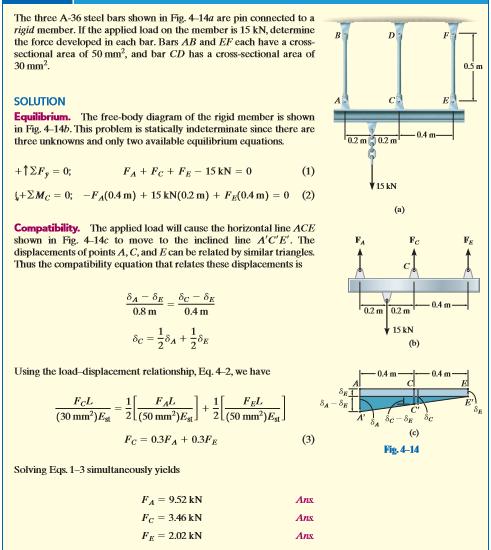
Chapter Tow. Simple strains
|
|
|
- Dortha Nelson
- 5 years ago
- Views:
Transcription

1 Chapter Tow Simple strains If a bar is subjected to a direct tension, the bar will change in length. If the bar has an original length L and change in length by an amount δl the strain produces is defined as follows Strain = change in length original length = δl L Strain represents a change in length divided by the original length, strain is dimensionless quantity. Strain assumed to be constant over the length under certain condition: - 1. The specimen must be constant cross section. 2. The material must be homogenous. 3. The load must be axial, that is produces uniform stress. 1
2 Proportional Limit (Hook s Law) From the origin to the point called proportional limit, the stress strain curve is a straight line. This linear relation was first noticed by Robert Hook in 1678 and is called Hook s Law that within the proportional limit, the stress is directly proportional to strain or σ ε or σ = k ε The constant of proportionality k is called the Modulus of Elasticity (E) or Young Modulus and is equal to the slope of the stress-strain diagram from the origin to proportional limit. Then σ = E ε Elastic limit The elastic limit is the limit beyond which the material will no longer go back to its original shape when the load is removed, or it is the maximum stress that may be developed such that there is no permanent deformation when the load is entirely removed. Elastic and Plastic Range The region in stress -strain diagram from the origin to proportional limit is called the elastic range. The region from proportional limit to rupture is called plastic range. Yield Point Yield point is the point at which the material will have an appreciable elongation or yielding without any increase in load. Ultimate Strength The maximum coordinate in the stress -strain diagram is the ultimate strength or tensile strength. Modulus of resilience 2
.")
3 Modulus of resilience is the work done on a unit volume of material as the force is gradually increased from the origin to plastic limit in N.m/m 3. This may be calculated as the area under the stress-strain curve from the origin up to the elastic limit (the shaded area in the figure). The resilience of the material is its ability to absorb energy without creating permanent distortion. Modulus of toughness Modulus of toughness is the work done on the unit volume of material as the force is gradually increased from the origin to rupture in N.m/m 3. This may be calculated as the area under the entire stress-strain curve from the origin to rupture. The toughness of a material is its ability to absorb energy without causing it to break. True Stress Strain Diagram Instead of always using the original cross-sectional area and specimen length to calculate the (engineering) stress and strain, we could have used the actual cross-sectional area and specimen length at the instant the load is measured. The values of stress and strain found from these measurements are called true stress and true strain, and a plot of their values is called the true stress strain diagram Working Stress, Allowable Stress and Factor of Safety. 3
4 Working stress is defined as the actual stress of a material under a given loading. The maximum safe stress that the material can carry is termed as the allowable stress. The45678 allowable stress should be limited to value not exceeding the proportional limit. However, since proportional limit is difficult to determine accurately, the allowable stress is taken as either the yield point or ultimate strength divided by a factor of safety. The ratio of this strength (ultimate or yield strength) to allowable strength is called the factor of safety. Factor of Safety = Maximum Stress Allowable Working Stress σw = σyp Nyp or σw = σult Nult Typical values changes from 2.5(for static loads) to 10 (for shock loads) σw = 1 2 σyp Comparative stress-strain diagram for different materials. 4

5 Yield strength determined by offset method. Axial Deformation In the liner portion of the stress -strain diagram, the stress is proportional to strain and is given by, σ = Eε Since σ = δ L and ε = δ L,then P A = E δ L Solving for δ, δ = PL AE δ = σl E To use this formula, there are three restrictions:- 1- The load must be axial. 2- The bar must have constant cross-section and be homogenous. 3- The stress must not exceed the proportional limit. 5

6 Shearing Strain Shearing strain defined as the angular change between tow perpendicular faces of differential element. The relation between shearing stress and shearing strain assuming Hook s Law to apply to shear shear stress τ = constant = G shear strain γ G: modulus of rigidity or shear modulus. tanγ = δs L Shear deformation The angle γ is usually very small,tanγ = γ γ = δs L τ = Gγ, τ=v/a δs = VL AE, V is the shearing force acting over the shearing area As. 6
7 108 (singer): An aluminum bar having a cross-sectional area of 160 mm 2 carries the axial loads at positions shown in figure, if E=70Gpa, compute the total deformation of the bar. Assume the bar is suitably braced to prevent buckling. 1 35kN 15kN 30kN 2 3 Solution 0.8m 1.0 m 0.6m δ1 = P1L1 A1E1 = 35 10^ = m (elongation) δ2 = P2L2 AE = = m (elongation) δ3 = P3L3 AE = = m (cntraction) δ = δ1 + δ2 + δ3 δ = δ = m = mm 7
8 211(singer): The rigid bars shown in figure are supported by roller at C and pinned at A and D. A steel rod at B helps support the load of 50 KN. Compute the vertical displacement of the roller at C. A B E=200 A=30 L=3m 3m 1.5m C 2m 50 2m D Solution: MD = = Rcy 4 Rcy = 25 kn MA = = 3T T = 37.5 kn δb = TL AE = δc 4.5 = δb = mm δc = mm = 2.81 m 8
9 120mm Example (201) Compute the total elongation caused by axial load of 100 KN applied to a bar 20mm thick,tapering from a width of (120mm)to (40mm) in length of (10m)as shown in figure.assume E=200*10 9 N/m 2. m 100kN 100kN X 10m n 20mm Solution: y y (4 * x 20) x 10 A 20(2 y) (160x 800) mm sec m-n,in a differential length dx,the elongation may be found from PL AE 0.5dx 160x *10 dx 160X 800) *10 (200*10 ( 6 9 From which the total elongation will be 10 dx x 160x ln( ) 10 ) 0 (3.13* ln 3.44* mm 9
10 Example: For the shown member what is the maximum force P applied s that the maximum deformation is 0.25 mm, plot deformation diagram. Es=210 KN/mm 2,Eal=70 KN/mm 2. Solution : δ = δs + δal δs = δal = Ps Ls As Es = P 300 (50) P 380 (100) 2 70 P 300 (50) P 380 (100) 2 70 = 0.25 P = kn 204 (singer): A uniform bar of length L,cross-sectional area A, and unit mass ρ is suspended vertically from one end.show that it s total elongation is δ = ρgl 2 /2E. If the total mass of the bar is M, show also that δ = MgL/2AE. Solution: δ = dδ P = Wy g = (ρay)g L = dy dδ = ρay AE dy L δ = ρayg AE dy dy 0 y L 10
11 = ρg L Ydy E 0 ; δ = ρg E Given that total mass M: L 2 2 dy ρ = M V ; ρ = M/AL δ = M AL. g E. L2 2 δ = MgL 2E OR another solution :- Mass per unit length =M/L y Wy Mass at y = M L. y Wy = M L. y M. g. y dy dδ = L AE δ = Mg LAE L y dy 0 = Mg y 2 ]L LAE 2 0 ; δ = MgL 2AE Example : A driven pile is supported to resist the force P. The force is transmitted to the soil by side friction (variable) as shown in figure. Find the total shortening in the pile. dy R R R P y y L 11 f = ky 2 y x
12 Solution P = f dy P L 0 ky^ 2dy ky^3 L kl^ k f 3P L^3 3P y L^3 2 R y 3P y L^ dy 3P L ^3 y 3 y 3 0 R Py3 L 3 PL AE d R AE dy L Rdy 0 AE 12
![L 0 Py L 3 P 3 AEL 3 dy AE 4 y L ] 4 0 PL 4AE A 2 4 D ; PL 2 D E 4-30 (Hibbler): The weight of kentlege exerts an axial force of P=1500 KN on the 300-mm diameter high strength concrete bore pile.](/docs-images/89/100132429/images/13-0.jpg "If the distribution of the resisting skin friction developed from the interaction between the soil and the surface of the pile is approximated as shown and the resisting bearing force F is required")
13 L 0 Py L 3 P 3 AEL 3 dy AE 4 y L ] 4 0 PL 4AE A 2 4 D ; PL 2 D E 4-30 (Hibbler): The weight of kentlege exerts an axial force of P=1500 KN on the 300-mm diameter high strength concrete bore pile. If the distribution of the resisting skin friction developed from the interaction between the soil and the surface of the pile is approximated as shown and the resisting bearing force F is required to be zero determine the maximum intensity P₀ KN/m for equilibrium. Also, find the corresponding elastic shortening of the pile. Neglect the weight of the pile. Ec=29 Gpa. Solution: Fy 0 F P * P
14 *The normal force developed in the pile is a function of y PL AE dy d P( y) dy AE x 12 P ( y) dy ; AE 0 2 x. y P. y P( y) 10.42y y y AE 2 dy y AE ; A (0.3) 2.93* mm 3 m 202(singer) : Tow steel bars AB and BC support a load P=30KN as shown in figure.area of ABis 300mm 2,area of bc is 500mm 2.If E=200 GPa,compute the horizontal and vertical movement of B. A A B P=30kN 4m C 3m B C B 14 B
15 1.6 From statics : Y1 X1 PAB =50 kn (tension) PBC= 40 k N (compression) X δ y2 y PL AE 3 50*10 *5000 AB 4.17mm( lengthening ) 9 300* 200* *10 * 4000 BC 1.6mm( shortening) 9 500* 200*10 x1 4 x x1 1.6 y2 3 4 y mm y y mm y mm 2 2 BB' (9.082) (1.6) 9. 22mm 15
16 Poisson s Ratio :Biaxial and Triaxial Deformations Hook s Law Stress α Strain Stress Strain = Constant E = Stress Strain = σ ε Lο Dο D Z X εx = Uniaxial Stress Do D Do = D Do ΔL Y εy = L L P υ = εx εy υ = Lateral Strain Longitudinal Strain υ Poison s Ratio Poison s Ratio : is the ratio between the lateral strain to the longitudinal strain. Application of Poison s Ratio to a two -dimensional stress system Tow dimensional stress system is one in which all the stresses lie within one plane such as the x-y plane. σy σx 16
17 εx = σx E In the x- direction resulting from σx, εx = σx/e In the y-direction resulting from σy, εy = σy/e In the x-direction resulting from σy, εx = υ( σx E ) In the y-direction resulting from the σx, εy = υ( σx E ) The total strain in the x-direction will be: σy υ E = 1 (σx υσy) E The total strain in the y-direction will be: Triaxial tensile stresses: εx = 1 [σx υ(σy + σz)] E εy = 1 [σy- υ(σz+σx)] E εz= 1 [σz υ(σx + σy)] E The relation between E, G and υ G = E 2(1 + υ) *The common values of Poisson s ratio are: for steel for most other metals. 0.2 for concrete. 17
18 221(singer): A solid aluminum shaft if 80-mm diameter fits concentrically in a hollow steel tube. Compute the minimum internal diameter of the steel tube so that no contact pressure exist when the aluminum shaft carries an axial compressive load of 400 KN.Assume x y P P x Solution: The axial compressive stress in the aluminum is: σ = P A , σx = π = 79.6 MN/m2 (0.08)2 4 For uniaxial stress, the transverse strain is: εy = υεx =- υσx E : εy = 1 3 ( ) εy = m m Therefore the required diameter clearance is δ = εl, δy = ( )(80) = mm εy = Do D D 18
19 The required internal diameter of the tube is found by adding this clearance to the original diameter of the aluminum shaft, thus giving, D = = mm Ans. σx = σy = σz = 223(Singer): A rectangular aluminum block is 100 mm long in the X-direction 75 mm wide in the Y-direction, and 50 mm thick in the Z-direction.It is subjected to triaxial loading consisting of uniform distributed tensile forces of (200KN) in the X-direction and uniformly distributed compressive forces of (160 KN) in the Y-direction and (220KN) in the Z-direction.If υ=1/3 and E=70GPa,determine a single distributed loading in the X- direction that would produce the same Z-deformation as the original loading. Solution: = N/m = N/m = N/m 2 εz = 1 [σz υ(σx + σy)] E = [ ( )] = m/m 19
20 *Single distributed load in the x-direction that would produce the same z deformation as the original loading means that the loads in the y&z directions will be zero. εz = 1 [σz υ(σx + σy)] E = [0 1 (σx + 0)] 3 σx = N m 2 P = σ A = = kn Example: In a tensile test on an aluminum bar of 57mm diameter and a length of 305 mm the total elongation is (0.24 mm) a tensile force of 124 kn,and the contraction in diameter is (0.015mm).Find E,υ and G for aluminum. Dο Z X Solution: εx = 1 [σx υ(σy + σz)] E Lο D σx = 0, σy = 0 εx = υ σy E εy = σy E ΔL Y P 20
21 εz = υσy E σy = P A = π 4 (57) = N/m^2 σy = MPa Lateral strain εy εx = Do D Do = D Do = = mm/mm 57 Longitudinal strain εy = L = 0.24 = mm/mm L 305 εy = σy E E = = MPa υ = lateral strain longitudinal strain = ( ) = G = E 2(1 + υ) = = MPa 2( ) Problem 225(Singer) A welded steel cylindrical drum made of a 10-mm plate has an internal diameter of 1.20 m. Compute the change in diameter that would be caused by an internal pressure of 1.5 MPa. Assume that Poisson's ratio is 0.30 and E = 200 GPa. 21
22 Problem 227 A 150-mm-long bronze tube, closed at its ends, is 80 mm in diameter and has a wall thickness of 3 mm. It fits without clearance in an 80-mm hole in a rigid block. The tube is then subjected to an internal pressure of 4.00 MPa. Assuming ν = 1/3 and E = 83 GPa, determine the tangential stress in the tube. 22
23 Statically Indeterminate Members When the reactive force or the internal resulting forces over a cross section exceed the number of independent equations of equilibrium, the structure is statically indeterminate. So how to solve such problems? To a free body diagram of the structure or a part of it, apply the equation s of static equilibrium. If there are more unknowns, obtain additional equations from the geometric relations between the elastic deformations produces by the loads. Problem 334 A reinforced concrete column 200 mm in diameter is designed to carry an axial compressive load of 300 kn. Determine the required area of the reinforcing steel if the allowable stresses are 6 MPa and 120 MPa for the concrete and steel, respectively. Use Eco = 14 GPa and Est = 200 GPa. 23
24 Solution 24
25 25
26 26

27 Problem 257 Three bars AB, AC, and AD are pinned together as shown in Fig. P-257. Initially, the assembly is stressfree. Horizontal movement of the joint at A is prevented by a short horizontal strut AE. Calculate the stress in each bar and the force in the strut AE when the assembly is used to support the load W = 10 kips. For each steel bar, A = 0.3 in.2 and E = psi. For the aluminum bar, A = 0.6. in.2 and E = psi. 27
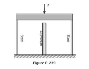
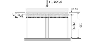
28 Problem 239 The rigid platform in Fig. P-239 has negligible mass and rests on two steel bars, each mm long. The center bar is aluminum and mm long. Compute the stress in the aluminum bar after the center load P = 400 kn has been applied. For each steel bar, the area is 1200 mm2 and E = 200 GPa. For the aluminum bar, the area is 2400 mm2 and E = 70 GPa. 28
29 29
30 Thermal stresses Thermal stresses or strains, in simple bar, may be found out as discussed below: - 1- Calculate the amount of deformation due to change of temperature with the assumption that the bar is free to expand or contract. 2- Calculate the load (or force) required to bring the deformed bar to the original length. 3- Calculate the stresses and strains in the bar caused by this load. δt = αl(tf Ti) = αl T where α is the coefficient of thermal expansion in m/m C, L is the length in meter, and Ti and Tf are the initial and final temperatures, respectively in C. 258(Singer): A steel rod 2.5m long is secured between tow walls. If the load on the rod is zero at 20 ₀ C, compute the stress when temperature drops to (- 20 ₀ C). The cross-sectional area of the rod is 1200mm 2 α=11.7μm/(m. ₀ C) and E=200 GPa. Solve assuming (a)that the wall is rigid and (b)that the wall spring together a total distance of 0.500mm as the temperature drops. Solution 30

 σ = 53.")
31 (a) δt = δp αl T = PL ; σ = P AE A σ = Eα T = ( )( )(40) σ = N m 2 *Note that Cancels out of the above equations, indicating that the stress is independent of the length of the rod. (b) δt = δp + X(yield) αl T = PL AE + x ( )(2.5)(40) = σ(2.5) ( ) σ = 53.6 MN/m 2 Note that the yield of the wall reduces the stress considerably, and also that the length of the rod does not canceled out as in part a. 31
32 259(Singer) : A rigid block having a mass of 5 Mg is supported by three rods symmetrically placed as shown in figure. Determine the stress in each rod after a temperature raise of 40 ₀ C. Use the data in the accompanying table. Each steel rods Bronze rod Area(mm 2 ) E(N/m 2 ) 200* *10 9 α (μm/ Bronze L=1m stee L=0.5m steel stee L=0.5m steel Initial position W=Mg=5000* 9.81 δts δps Pb δtb δpb Final position Ps Solution δts + δps = δtb + δpb ((αl T)s + ( PL ) s = (αl T)b + (PL ) b AE AE ( Ps(0.5) )(0.5)(40) + ( )( ) = ( Pb(1) )(1)(40) + ( )( ) Simplify the above equation, Ps 2.68Pb = N (a) Fy = 0 32
33 2Ps + Pb = 5000(9.81) = N (b) Solving Eq.s (a) and (b) Ps = 37.0 Pb = 25.0 kn kn The negative sign for Pb means that the load Pb acts oppositely to that assumed: That is bronze rod is actually in compression and suitable position must be made to prevent bukling. The stresses are [σ = P ] σs = A = 74.0 MN (tension) Ans. m2 σb = = 27.8 MN m 2 (compression) Ans. 260.(Singer) :Using the data in example 259,determine the temperature rise necessary to cause all the applied load to be supported by the steel rods. Solution Ps = 1 (5000)(9.81) = kn 2 δtb = δts + δps (αl T)b = (αl Ts) + ( PL AE ) s δts δps δtb Ps ( )(1)( T) = ( )(0.5)( T) + T = 9.4 (24.53)(10 3 )(0.5) ( )( ) 33
34 roblem 261 A steel rod with a cross-sectional area of 0.25 in2 is stretched between two fixed points. The tensile load at 70 F is 1200 lb. What will be the stress at 0 F? At what temperature will the stress be zero? Assume α = in / (in F) and E = psi. Solution Problem 263 Steel railroad reels 10 m long are laid with a clearance of 3 mm at a temperature of 15 C. At what temperature, will the rails just touch? What stress would be induced in the rails at that temperature if there were no initial clearance? Assume α = 11.7 µm/(m C) and E = 200 GPa. 34
35 Bronze Steel Bronze 250mm 266(Singer): At 20 ₀ C, a rigid slab having a mass of 55 Mg placed upon two bronze rods and one steel rod as shown. At what temperature will the stress in the steel rod be zero? For the steel rod A=600mm 2,E=200*10 9 MPa and α=11.7 μm/(m. ₀ C).For each bronze rods A=6000mm 2,E=83*10 9 N/m,and α=19.0 μm/(m. ₀ C). Solution 55Mg δs δb ΔTb δps ΔTs ΔP 50mm 35
36 δst = δb (compatibility) δst = δts δps δb = δtb δpb αslsδt PsLs AsEs = αblbδt PbLb AbEb Fy = 0.(equilibrium) = 2Pb ; Ps = 0 Pb = N ΔT PsLs AsEs = ΔT ΔT = 109 ΔT = Tf Ti 109 = Tf 20 Tf = 129 Problem 270 A bronze sleeve is slipped over a steel bolt and held in place by a nut that is turned to produce an initial stress of 2000 psi in the bronze. For the steel bolt, A = 0.75 in2, E = psi, and α = in/(in F). For the bronze sleeve, A = 1.5 in2, E = psi and α = in/(in F). After a temperature rise of 100 F, find the final stress in each material. 36

37 Solution: 37
38 38
39 Problem 275 A rigid horizontal bar of negligible mass is connected to two rods as shown in Fig. If the system is initially stress-free. Calculate the temperature change that will cause a tensile stress of 90 MPa in the brass rod. Assume that both rods are subjected to the change in temperature. 39
40 40
 diam.pins as shown in figure. Find the shear stress set up in the pins if, after pinning, the temperature is raised by 50 ₒ C.")
41 Example: A composite bar is constructed from a steel rod of (25 mm) diameter surrounded by a copper tube of (50 mm) outside diameter and (25 mm) inside diameter. The rod and tube are joined by tow (20 mm) diam.pins as shown in figure. Find the shear stress set up in the pins if, after pinning, the temperature is raised by 50 ₒ C. For steel E= 210 GN/m 2 and α = 11*10-6 per ₒ C, for copper E= 105 GN/m 2 and α = 17*10-6 per ₒ C. In this case the copper attempts to expand more than the steel, thus tending to shear the pins joining the two 41
42 42
43 43
Strength of Material. Shear Strain. Dr. Attaullah Shah
 Strength of Material Shear Strain Dr. Attaullah Shah Shear Strain TRIAXIAL DEFORMATION Poisson's Ratio Relationship Between E, G, and ν BIAXIAL DEFORMATION Bulk Modulus of Elasticity or Modulus of Volume
ME 243. Mechanics of Solids
 ME 243 Mechanics of Solids Lecture 2: Stress and Strain Ahmad Shahedi Shakil Lecturer, Dept. of Mechanical Engg, BUET E-mail: sshakil@me.buet.ac.bd, shakil6791@gmail.com Website: teacher.buet.ac.bd/sshakil
INTRODUCTION TO STRAIN
 SIMPLE STRAIN INTRODUCTION TO STRAIN In general terms, Strain is a geometric quantity that measures the deformation of a body. There are two types of strain: normal strain: characterizes dimensional changes,
NORMAL STRESS. The simplest form of stress is normal stress/direct stress, which is the stress perpendicular to the surface on which it acts.
 NORMAL STRESS The simplest form of stress is normal stress/direct stress, which is the stress perpendicular to the surface on which it acts. σ = force/area = P/A where σ = the normal stress P = the centric
Direct and Shear Stress
 Direct and Shear Stress 1 Direct & Shear Stress When a body is pulled by a tensile force or crushed by a compressive force, the loading is said to be direct. Direct stresses are also found to arise when
MECE 3321 MECHANICS OF SOLIDS CHAPTER 3
 MECE 3321 MECHANICS OF SOLIDS CHAPTER 3 Samantha Ramirez TENSION AND COMPRESSION TESTS Tension and compression tests are used primarily to determine the relationship between σ avg and ε avg in any material.
Chapter Two: Mechanical Properties of materials
 Chapter Two: Mechanical Properties of materials Time : 16 Hours An important consideration in the choice of a material is the way it behave when subjected to force. The mechanical properties of a material
[5] Stress and Strain
![[5] Stress and Strain](/thumbs/95/123344550.jpg "[5] Stress and Strain") [5] Stress and Strain Page 1 of 34 [5] Stress and Strain [5.1] Internal Stress of Solids [5.2] Design of Simple Connections (will not be covered in class) [5.3] Deformation and Strain [5.4] Hooke s Law
[5] Stress and Strain Page 1 of 34 [5] Stress and Strain [5.1] Internal Stress of Solids [5.2] Design of Simple Connections (will not be covered in class) [5.3] Deformation and Strain [5.4] Hooke s Law
Samantha Ramirez, MSE. Stress. The intensity of the internal force acting on a specific plane (area) passing through a point. F 2
 passing through a point. F 2") Samantha Ramirez, MSE Stress The intensity of the internal force acting on a specific plane (area) passing through a point. Δ ΔA Δ z Δ 1 2 ΔA Δ x Δ y ΔA is an infinitesimal size area with a uniform force
Samantha Ramirez, MSE Stress The intensity of the internal force acting on a specific plane (area) passing through a point. Δ ΔA Δ z Δ 1 2 ΔA Δ x Δ y ΔA is an infinitesimal size area with a uniform force
Chapter 5 CENTRIC TENSION OR COMPRESSION ( AXIAL LOADING )
") Chapter 5 CENTRIC TENSION OR COMPRESSION ( AXIAL LOADING ) 5.1 DEFINITION A construction member is subjected to centric (axial) tension or compression if in any cross section the single distinct stress
Chapter 5 CENTRIC TENSION OR COMPRESSION ( AXIAL LOADING ) 5.1 DEFINITION A construction member is subjected to centric (axial) tension or compression if in any cross section the single distinct stress
N = Shear stress / Shear strain
 UNIT - I 1. What is meant by factor of safety? [A/M-15] It is the ratio between ultimate stress to the working stress. Factor of safety = Ultimate stress Permissible stress 2. Define Resilience. [A/M-15]
STRESS, STRAIN AND DEFORMATION OF SOLIDS
 VELAMMAL COLLEGE OF ENGINEERING AND TECHNOLOGY, MADURAI 625009 DEPARTMENT OF CIVIL ENGINEERING CE8301 STRENGTH OF MATERIALS I -------------------------------------------------------------------------------------------------------------------------------
Strength of Materials (15CV 32)
") Strength of Materials (15CV 32) Module 1 : Simple Stresses and Strains Dr. H. Ananthan, Professor, VVIET,MYSURU 8/21/2017 Introduction, Definition and concept and of stress and strain. Hooke s law, Stress-Strain
Strength of Materials (15CV 32) Module 1 : Simple Stresses and Strains Dr. H. Ananthan, Professor, VVIET,MYSURU 8/21/2017 Introduction, Definition and concept and of stress and strain. Hooke s law, Stress-Strain
Chapter 4-b Axially Loaded Members
 CIVL 222 STRENGTH OF MATERIALS Chapter 4-b Axially Loaded Members AXIAL LOADED MEMBERS Today s Objectives: Students will be able to: a) Determine the elastic deformation of axially loaded member b) Apply
The University of Melbourne Engineering Mechanics
 The University of Melbourne 436-291 Engineering Mechanics Tutorial Four Poisson s Ratio and Axial Loading Part A (Introductory) 1. (Problem 9-22 from Hibbeler - Statics and Mechanics of Materials) A short
CHAPTER 3 THE EFFECTS OF FORCES ON MATERIALS
 CHAPTER THE EFFECTS OF FORCES ON MATERIALS EXERCISE 1, Page 50 1. A rectangular bar having a cross-sectional area of 80 mm has a tensile force of 0 kn applied to it. Determine the stress in the bar. Stress
EMA 3702 Mechanics & Materials Science (Mechanics of Materials) Chapter 2 Stress & Strain - Axial Loading
 Chapter 2 Stress & Strain - Axial Loading") MA 3702 Mechanics & Materials Science (Mechanics of Materials) Chapter 2 Stress & Strain - Axial Loading MA 3702 Mechanics & Materials Science Zhe Cheng (2018) 2 Stress & Strain - Axial Loading Statics
MA 3702 Mechanics & Materials Science (Mechanics of Materials) Chapter 2 Stress & Strain - Axial Loading MA 3702 Mechanics & Materials Science Zhe Cheng (2018) 2 Stress & Strain - Axial Loading Statics
Constitutive Equations (Linear Elasticity)
") Constitutive quations (Linear lasticity) quations that characterize the physical properties of the material of a system are called constitutive equations. It is possible to find the applied stresses knowing
Constitutive quations (Linear lasticity) quations that characterize the physical properties of the material of a system are called constitutive equations. It is possible to find the applied stresses knowing
A concrete cylinder having a a diameter of of in. mm and elasticity. Stress and Strain: Stress and Strain: 0.
 2011 earson Education, Inc., Upper Saddle River, NJ. ll rights reserved. This material is protected under all copyright laws as they currently 8 1. 3 1. concrete cylinder having a a diameter of of 6.00
Unit I Stress and Strain
 Unit I Stress and Strain Stress and strain at a point Tension, Compression, Shear Stress Hooke s Law Relationship among elastic constants Stress Strain Diagram for Mild Steel, TOR steel, Concrete Ultimate
R13. II B. Tech I Semester Regular Examinations, Jan MECHANICS OF SOLIDS (Com. to ME, AME, AE, MTE) PART-A
 PART-A") SET - 1 II B. Tech I Semester Regular Examinations, Jan - 2015 MECHANICS OF SOLIDS (Com. to ME, AME, AE, MTE) Time: 3 hours Max. Marks: 70 Note: 1. Question Paper consists of two parts (Part-A and Part-B)
SET - 1 II B. Tech I Semester Regular Examinations, Jan - 2015 MECHANICS OF SOLIDS (Com. to ME, AME, AE, MTE) Time: 3 hours Max. Marks: 70 Note: 1. Question Paper consists of two parts (Part-A and Part-B)
Mechanical Properties of Materials
 Mechanical Properties of Materials Strains Material Model Stresses Learning objectives Understand the qualitative and quantitative description of mechanical properties of materials. Learn the logic of
Solid Mechanics Chapter 1: Tension, Compression and Shear
 Solid Mechanics Chapter 1: Tension, Compression and Shear Dr. Imran Latif Department of Civil and Environmental Engineering College of Engineering University of Nizwa (UoN) 1 Why do we study Mechanics
Downloaded from Downloaded from / 1
 PURWANCHAL UNIVERSITY III SEMESTER FINAL EXAMINATION-2002 LEVEL : B. E. (Civil) SUBJECT: BEG256CI, Strength of Material Full Marks: 80 TIME: 03:00 hrs Pass marks: 32 Candidates are required to give their
Free Body Diagram: Solution: The maximum load which can be safely supported by EACH of the support members is: ANS: A =0.217 in 2
 Problem 10.9 The angle β of the system in Problem 10.8 is 60. The bars are made of a material that will safely support a tensile normal stress of 8 ksi. Based on this criterion, if you want to design the
Theory at a Glance (for IES, GATE, PSU)
") 1. Stress and Strain Theory at a Glance (for IES, GATE, PSU) 1.1 Stress () When a material is subjected to an external force, a resisting force is set up within the component. The internal resistance force
1. Stress and Strain Theory at a Glance (for IES, GATE, PSU) 1.1 Stress () When a material is subjected to an external force, a resisting force is set up within the component. The internal resistance force
QUESTION BANK SEMESTER: III SUBJECT NAME: MECHANICS OF SOLIDS
 QUESTION BANK SEMESTER: III SUBJECT NAME: MECHANICS OF SOLIDS UNIT 1- STRESS AND STRAIN PART A (2 Marks) 1. Define longitudinal strain and lateral strain. 2. State Hooke s law. 3. Define modular ratio,
Stress-Strain Behavior
 Stress-Strain Behavior 6.3 A specimen of aluminum having a rectangular cross section 10 mm 1.7 mm (0.4 in. 0.5 in.) is pulled in tension with 35,500 N (8000 lb f ) force, producing only elastic deformation.
UNIT I SIMPLE STRESSES AND STRAINS
 Subject with Code : SM-1(15A01303) Year & Sem: II-B.Tech & I-Sem SIDDHARTH GROUP OF INSTITUTIONS :: PUTTUR Siddharth Nagar, Narayanavanam Road 517583 QUESTION BANK (DESCRIPTIVE) UNIT I SIMPLE STRESSES
UNIT 1 STRESS STRAIN AND DEFORMATION OF SOLIDS, STATES OF STRESS 1. Define stress. When an external force acts on a body, it undergoes deformation.
 UNIT 1 STRESS STRAIN AND DEFORMATION OF SOLIDS, STATES OF STRESS 1. Define stress. When an external force acts on a body, it undergoes deformation. At the same time the body resists deformation. The magnitude
Purpose of this Guide: To thoroughly prepare students for the exact types of problems that will be on Exam 3.
 ES230 STRENGTH OF MTERILS Exam 3 Study Guide Exam 3: Wednesday, March 8 th in-class Updated 3/3/17 Purpose of this Guide: To thoroughly prepare students for the exact types of problems that will be on
MECHANICS OF MATERIALS
 Third E CHAPTER 2 Stress MECHANICS OF MATERIALS Ferdinand P. Beer E. Russell Johnston, Jr. John T. DeWolf Lecture Notes: J. Walt Oler Texas Tech University and Strain Axial Loading Contents Stress & Strain:
Simple Stresses in Machine Parts
 Simple Stresses in Machine Parts 87 C H A P T E R 4 Simple Stresses in Machine Parts 1. Introduction.. Load. 3. Stress. 4. Strain. 5. Tensile Stress and Strain. 6. Compressive Stress and Strain. 7. Young's
Stress Analysis Lecture 3 ME 276 Spring Dr./ Ahmed Mohamed Nagib Elmekawy
 Stress Analysis Lecture 3 ME 276 Spring 2017-2018 Dr./ Ahmed Mohamed Nagib Elmekawy Axial Stress 2 Beam under the action of two tensile forces 3 Beam under the action of two tensile forces 4 Shear Stress
Tensile stress strain curves for different materials. Shows in figure below
 Tensile stress strain curves for different materials. Shows in figure below Furthermore, the modulus of elasticity of several materials effected by increasing temperature, as is shown in Figure Asst. Lecturer
UNIT-I STRESS, STRAIN. 1. A Member A B C D is subjected to loading as shown in fig determine the total elongation. Take E= 2 x10 5 N/mm 2
 UNIT-I STRESS, STRAIN 1. A Member A B C D is subjected to loading as shown in fig determine the total elongation. Take E= 2 x10 5 N/mm 2 Young s modulus E= 2 x10 5 N/mm 2 Area1=900mm 2 Area2=400mm 2 Area3=625mm
PDDC 1 st Semester Civil Engineering Department Assignments of Mechanics of Solids [ ] Introduction, Fundamentals of Statics
![PDDC 1 st Semester Civil Engineering Department Assignments of Mechanics of Solids [ ] Introduction, Fundamentals of Statics](/thumbs/92/109382806.jpg "PDDC 1 st Semester Civil Engineering Department Assignments of Mechanics of Solids [ ] Introduction, Fundamentals of Statics") Page1 PDDC 1 st Semester Civil Engineering Department Assignments of Mechanics of Solids [2910601] Introduction, Fundamentals of Statics 1. Differentiate between Scalar and Vector quantity. Write S.I.
Page1 PDDC 1 st Semester Civil Engineering Department Assignments of Mechanics of Solids [2910601] Introduction, Fundamentals of Statics 1. Differentiate between Scalar and Vector quantity. Write S.I.
KINGS COLLEGE OF ENGINEERING DEPARTMENT OF MECHANICAL ENGINEERING QUESTION BANK. Subject code/name: ME2254/STRENGTH OF MATERIALS Year/Sem:II / IV
 KINGS COLLEGE OF ENGINEERING DEPARTMENT OF MECHANICAL ENGINEERING QUESTION BANK Subject code/name: ME2254/STRENGTH OF MATERIALS Year/Sem:II / IV UNIT I STRESS, STRAIN DEFORMATION OF SOLIDS PART A (2 MARKS)
6.4 A cylindrical specimen of a titanium alloy having an elastic modulus of 107 GPa ( psi) and
 and") 6.4 A cylindrical specimen of a titanium alloy having an elastic modulus of 107 GPa (15.5 10 6 psi) and an original diameter of 3.8 mm (0.15 in.) will experience only elastic deformation when a tensile
6.4 A cylindrical specimen of a titanium alloy having an elastic modulus of 107 GPa (15.5 10 6 psi) and an original diameter of 3.8 mm (0.15 in.) will experience only elastic deformation when a tensile
RODS: THERMAL STRESS AND STRESS CONCENTRATION
 RODS: HERML SRESS ND SRESS CONCENRION Example 5 rod of length L, cross-sectional area, and modulus of elasticity E, has been placed inside a tube of the same length L, but of cross-sectional area and modulus
2. Rigid bar ABC supports a weight of W = 50 kn. Bar ABC is pinned at A and supported at B by rod (1). What is the axial force in rod (1)?
. What is the axial force in rod (1)?") IDE 110 S08 Test 1 Name: 1. Determine the internal axial forces in segments (1), (2) and (3). (a) N 1 = kn (b) N 2 = kn (c) N 3 = kn 2. Rigid bar ABC supports a weight of W = 50 kn. Bar ABC is pinned at
IDE 110 S08 Test 1 Name: 1. Determine the internal axial forces in segments (1), (2) and (3). (a) N 1 = kn (b) N 2 = kn (c) N 3 = kn 2. Rigid bar ABC supports a weight of W = 50 kn. Bar ABC is pinned at
Russell C. Hibbeler. Chapter 1: Stress
 Russell C. Hibbeler Chapter 1: Stress Introduction Mechanics of materials is a study of the relationship between the external loads on a body and the intensity of the internal loads within the body. This
CHAPTER OBJECTIVES CHAPTER OUTLINE. 4. Axial Load
 CHAPTER OBJECTIVES Determine deformation of axially loaded members Develop a method to find support reactions when it cannot be determined from euilibrium euations Analyze the effects of thermal stress
PES Institute of Technology
 PES Institute of Technology Bangalore south campus, Bangalore-5460100 Department of Mechanical Engineering Faculty name : Madhu M Date: 29/06/2012 SEM : 3 rd A SEC Subject : MECHANICS OF MATERIALS Subject
STRENGTH OF MATERIALS-I. Unit-1. Simple stresses and strains
 STRENGTH OF MATERIALS-I Unit-1 Simple stresses and strains 1. What is the Principle of surveying 2. Define Magnetic, True & Arbitrary Meridians. 3. Mention different types of chains 4. Differentiate between
Mechanics of Solids. Mechanics Of Solids. Suraj kr. Ray Department of Civil Engineering
 Mechanics Of Solids Suraj kr. Ray (surajjj2445@gmail.com) Department of Civil Engineering 1 Mechanics of Solids is a branch of applied mechanics that deals with the behaviour of solid bodies subjected
4.MECHANICAL PROPERTIES OF MATERIALS
 4.MECHANICAL PROPERTIES OF MATERIALS The diagram representing the relation between stress and strain in a given material is an important characteristic of the material. To obtain the stress-strain diagram
18.Define the term modulus of resilience. May/June Define Principal Stress. 20. Define Hydrostatic Pressure.
 CE6306 STREGNTH OF MATERIALS Question Bank Unit-I STRESS, STRAIN, DEFORMATION OF SOLIDS PART-A 1. Define Poison s Ratio May/June 2009 2. What is thermal stress? May/June 2009 3. Estimate the load carried
QUESTION BANK DEPARTMENT: CIVIL SEMESTER: III SUBJECT CODE: CE2201 SUBJECT NAME: MECHANICS OF SOLIDS UNIT 1- STRESS AND STRAIN PART A
 DEPARTMENT: CIVIL SUBJECT CODE: CE2201 QUESTION BANK SEMESTER: III SUBJECT NAME: MECHANICS OF SOLIDS UNIT 1- STRESS AND STRAIN PART A (2 Marks) 1. Define longitudinal strain and lateral strain. 2. State
MECHANICS OF MATERIALS
 CHATR Stress MCHANICS OF MATRIALS and Strain Axial Loading Stress & Strain: Axial Loading Suitability of a structure or machine may depend on the deformations in the structure as well as the stresses induced
MATERIALS FOR CIVIL AND CONSTRUCTION ENGINEERS
 MATERIALS FOR CIVIL AND CONSTRUCTION ENGINEERS 3 rd Edition Michael S. Mamlouk Arizona State University John P. Zaniewski West Virginia University Solution Manual FOREWORD This solution manual includes
1. A pure shear deformation is shown. The volume is unchanged. What is the strain tensor.
 Elasticity Homework Problems 2014 Section 1. The Strain Tensor. 1. A pure shear deformation is shown. The volume is unchanged. What is the strain tensor. 2. Given a steel bar compressed with a deformation
Mechanics of Materials II. Chapter III. A review of the fundamental formulation of stress, strain, and deflection
 Mechanics of Materials II Chapter III A review of the fundamental formulation of stress, strain, and deflection Outline Introduction Assumtions and limitations Axial loading Torsion of circular shafts
Mechanics of Materials Primer
 Mechanics of Materials rimer Notation: A = area (net = with holes, bearing = in contact, etc...) b = total width of material at a horizontal section d = diameter of a hole D = symbol for diameter E = modulus
ME 2570 MECHANICS OF MATERIALS
 ME 2570 MECHANICS OF MATERIALS Chapter III. Mechanical Properties of Materials 1 Tension and Compression Test The strength of a material depends on its ability to sustain a load without undue deformation
Name :. Roll No. :... Invigilator s Signature :.. CS/B.TECH (CE-NEW)/SEM-3/CE-301/ SOLID MECHANICS
/SEM-3/CE-301/ SOLID MECHANICS") Name :. Roll No. :..... Invigilator s Signature :.. 2011 SOLID MECHANICS Time Allotted : 3 Hours Full Marks : 70 The figures in the margin indicate full marks. Candidates are required to give their answers
Name :. Roll No. :..... Invigilator s Signature :.. 2011 SOLID MECHANICS Time Allotted : 3 Hours Full Marks : 70 The figures in the margin indicate full marks. Candidates are required to give their answers
five Mechanics of Materials 1 ARCHITECTURAL STRUCTURES: FORM, BEHAVIOR, AND DESIGN DR. ANNE NICHOLS SUMMER 2017 lecture
 ARCHITECTURAL STRUCTURES: FORM, BEHAVIOR, AND DESIGN DR. ANNE NICHOLS SUMMER 2017 lecture five mechanics www.carttalk.com of materials Mechanics of Materials 1 Mechanics of Materials MECHANICS MATERIALS
MAAE 2202 A. Come to the PASS workshop with your mock exam complete. During the workshop you can work with other students to review your work.
 It is most beneficial to you to write this mock final exam UNDER EXAM CONDITIONS. This means: Complete the exam in 3 hours. Work on your own. Keep your textbook closed. Attempt every question. After the
MECHANICS OF MATERIALS
 Third CHTR Stress MCHNICS OF MTRIS Ferdinand. Beer. Russell Johnston, Jr. John T. DeWolf ecture Notes: J. Walt Oler Texas Tech University and Strain xial oading Contents Stress & Strain: xial oading Normal
ISHIK UNIVERSITY DEPARTMENT OF MECHATRONICS ENGINEERING
 ISHIK UNIVERSITY DEPARTMENT OF MECHATRONICS ENGINEERING QUESTION BANK FOR THE MECHANICS OF MATERIALS-I 1. A rod 150 cm long and of diameter 2.0 cm is subjected to an axial pull of 20 kn. If the modulus
SRI CHANDRASEKHARENDRA SARASWATHI VISWA MAHAVIDHYALAYA
 SRI CHANDRASEKHARENDRA SARASWATHI VISWA MAHAVIDHYALAYA (Declared as Deemed-to-be University under Section 3 of the UGC Act, 1956, Vide notification No.F.9.9/92-U-3 dated 26 th May 1993 of the Govt. of
The science of elasticity
 The science of elasticity In 1676 Hooke realized that 1.Every kind of solid changes shape when a mechanical force acts on it. 2.It is this change of shape which enables the solid to supply the reaction
Introduction to Engineering Materials ENGR2000. Dr. Coates
 Introduction to Engineering Materials ENGR2 Chapter 6: Mechanical Properties of Metals Dr. Coates 6.2 Concepts of Stress and Strain tension compression shear torsion Tension Tests The specimen is deformed
Mechanical Design in Optical Engineering. For a prismatic bar of length L in tension by axial forces P we have determined:
 Deformation of Axial Members For a prismatic bar of length L in tension by axial forces P we have determined: σ = P A δ ε = L It is important to recall that the load P must act on the centroid of the cross
Aluminum shell. Brass core. 40 in
 PROBLEM #1 (22 points) A solid brass core is connected to a hollow rod made of aluminum. Both are attached at each end to a rigid plate as shown in Fig. 1. The moduli of aluminum and brass are EA=11,000
CHAPTER 5 Statically Determinate Plane Trusses
 CHAPTER 5 Statically Determinate Plane Trusses TYPES OF ROOF TRUSS TYPES OF ROOF TRUSS ROOF TRUSS SETUP ROOF TRUSS SETUP OBJECTIVES To determine the STABILITY and DETERMINACY of plane trusses To analyse
CHAPTER 5 Statically Determinate Plane Trusses TYPES OF ROOF TRUSS
 CHAPTER 5 Statically Determinate Plane Trusses TYPES OF ROOF TRUSS 1 TYPES OF ROOF TRUSS ROOF TRUSS SETUP 2 ROOF TRUSS SETUP OBJECTIVES To determine the STABILITY and DETERMINACY of plane trusses To analyse
CHAPTER 4: BENDING OF BEAMS
 (74) CHAPTER 4: BENDING OF BEAMS This chapter will be devoted to the analysis of prismatic members subjected to equal and opposite couples M and M' acting in the same longitudinal plane. Such members are
Solution: T, A1, A2, A3, L1, L2, L3, E1, E2, E3, P are known Five equations in five unknowns, F1, F2, F3, ua and va
 ME 323 Examination # 1 February 18, 2016 Name (Print) (Last) (First) Instructor PROBLEM #1 (20 points) A structure is constructed from members 1, 2 and 3, with these members made up of the same material
(48) CHAPTER 3: TORSION
 CHAPTER 3: TORSION") (48) CHAPTER 3: TORSION Introduction: In this chapter structural members and machine parts that are in torsion will be considered. More specifically, you will analyze the stresses and strains in members
(48) CHAPTER 3: TORSION Introduction: In this chapter structural members and machine parts that are in torsion will be considered. More specifically, you will analyze the stresses and strains in members
D : SOLID MECHANICS. Q. 1 Q. 9 carry one mark each. Q.1 Find the force (in kn) in the member BH of the truss shown.
 in the member BH of the truss shown.") D : SOLID MECHANICS Q. 1 Q. 9 carry one mark each. Q.1 Find the force (in kn) in the member BH of the truss shown. Q.2 Consider the forces of magnitude F acting on the sides of the regular hexagon having
D : SOLID MECHANICS Q. 1 Q. 9 carry one mark each. Q.1 Find the force (in kn) in the member BH of the truss shown. Q.2 Consider the forces of magnitude F acting on the sides of the regular hexagon having
MECHANICS OF SOLIDS. (For B.E. Mechanical Engineering Students) As per New Revised Syllabus of APJ Abdul Kalam Technological University
 As per New Revised Syllabus of APJ Abdul Kalam Technological University") MECHANICS OF SOLIDS (For B.E. Mechanical Engineering Students) As per New Revised Syllabus of APJ Abdul Kalam Technological University Dr. S.Ramachandran, M.E., Ph.D., Mr. V.J. George, M.E., Mr. S. Kumaran,
MECHANICS OF SOLIDS (For B.E. Mechanical Engineering Students) As per New Revised Syllabus of APJ Abdul Kalam Technological University Dr. S.Ramachandran, M.E., Ph.D., Mr. V.J. George, M.E., Mr. S. Kumaran,
SN QUESTION YEAR MARK 1. State and prove the relationship between shearing stress and rate of change of bending moment at a section in a loaded beam.
 ALPHA COLLEGE OF ENGINEERING AND TECHNOLOGY DEPARTMENT OF MECHANICAL ENGINEERING MECHANICS OF SOLIDS (21000) ASSIGNMENT 1 SIMPLE STRESSES AND STRAINS SN QUESTION YEAR MARK 1 State and prove the relationship
Chapter 7. Highlights:
 Chapter 7 Highlights: 1. Understand the basic concepts of engineering stress and strain, yield strength, tensile strength, Young's(elastic) modulus, ductility, toughness, resilience, true stress and true
EDEXCEL NATIONAL CERTIFICATE/DIPLOMA MECHANICAL PRINCIPLES AND APPLICATIONS NQF LEVEL 3 OUTCOME 1 - LOADING SYSTEMS TUTORIAL 3 LOADED COMPONENTS
 EDEXCEL NATIONAL CERTIICATE/DIPLOMA MECHANICAL PRINCIPLES AND APPLICATIONS NQ LEVEL 3 OUTCOME 1 - LOADING SYSTEMS TUTORIAL 3 LOADED COMPONENTS 1. Be able to determine the effects of loading in static engineering
BE Semester- I ( ) Question Bank (MECHANICS OF SOLIDS)
 Question Bank (MECHANICS OF SOLIDS)") BE Semester- I ( ) Question Bank (MECHANICS OF SOLIDS) All questions carry equal marks(10 marks) Q.1 (a) Write the SI units of following quantities and also mention whether it is scalar or vector: (i)
BE Semester- I ( ) Question Bank (MECHANICS OF SOLIDS) All questions carry equal marks(10 marks) Q.1 (a) Write the SI units of following quantities and also mention whether it is scalar or vector: (i)
Sub. Code:
 Important Instructions to examiners: ) The answers should be examined by key words and not as word-to-word as given in the model answer scheme. ) The model answer and the answer written by candidate may
QUESTION BANK ENGINEERS ACADEMY. PL 4Ed d. Ed d. 4PL Ed d. 4Ed d. 42 Axially Loaded Members Junior Engineer
 NGINRS CDMY xially oaded Members Junior ngineer QUSTION BNK 1. The stretch in a steel rod of circular section, having a length subjected to a tensile load P and tapering uniformly from a diameter d 1 at
Chapter 12. Static Equilibrium and Elasticity
 Chapter 12 Static Equilibrium and Elasticity Static Equilibrium Equilibrium implies that the object moves with both constant velocity and constant angular velocity relative to an observer in an inertial
March 24, Chapter 4. Deflection and Stiffness. Dr. Mohammad Suliman Abuhaiba, PE
 Chapter 4 Deflection and Stiffness 1 2 Chapter Outline Spring Rates Tension, Compression, and Torsion Deflection Due to Bending Beam Deflection Methods Beam Deflections by Superposition Strain Energy Castigliano
ENG1001 Engineering Design 1
 ENG1001 Engineering Design 1 Structure & Loads Determine forces that act on structures causing it to deform, bend, and stretch Forces push/pull on objects Structures are loaded by: > Dead loads permanent
The problem of transmitting a torque or rotary motion from one plane to another is frequently encountered in machine design.
 CHAPER ORSION ORSION orsion refers to the twisting of a structural member when it is loaded by moments/torques that produce rotation about the longitudinal axis of the member he problem of transmitting
Structural Analysis I Chapter 4 - Torsion TORSION
 ORSION orsional stress results from the action of torsional or twisting moments acting about the longitudinal axis of a shaft. he effect of the application of a torsional moment, combined with appropriate
Consider an elastic spring as shown in the Fig.2.4. When the spring is slowly
 .3 Strain Energy Consider an elastic spring as shown in the Fig..4. When the spring is slowly pulled, it deflects by a small amount u 1. When the load is removed from the spring, it goes back to the original
Determine the resultant internal loadings acting on the cross section at C of the beam shown in Fig. 1 4a.
 E X M P L E 1.1 Determine the resultant internal loadings acting on the cross section at of the beam shown in Fig. 1 a. 70 N/m m 6 m Fig. 1 Support Reactions. This problem can be solved in the most direct
Mechanical properties 1 Elastic behaviour of materials
 MME131: Lecture 13 Mechanical properties 1 Elastic behaviour of materials A. K. M. B. Rashid Professor, Department of MME BUET, Dhaka Today s Topics Deformation of material under the action of a mechanical
CIV 207 Winter For practice
 CIV 07 Winter 009 Assignment #10 Friday, March 0 th Complete the first three questions. Submit your work to Box #5 on the th floor of the MacDonald building by 1 noon on Tuesday March 31 st. No late submissions
CIVIL DEPARTMENT MECHANICS OF STRUCTURES- ASSIGNMENT NO 1. Brach: CE YEAR:
 MECHANICS OF STRUCTURES- ASSIGNMENT NO 1 SEMESTER: V 1) Find the least moment of Inertia about the centroidal axes X-X and Y-Y of an unequal angle section 125 mm 75 mm 10 mm as shown in figure 2) Determine
[8] Bending and Shear Loading of Beams
![[8] Bending and Shear Loading of Beams](/thumbs/92/110949676.jpg "[8] Bending and Shear Loading of Beams") [8] Bending and Shear Loading of Beams Page 1 of 28 [8] Bending and Shear Loading of Beams [8.1] Bending of Beams (will not be covered in class) [8.2] Bending Strain and Stress [8.3] Shear in Straight
[8] Bending and Shear Loading of Beams Page 1 of 28 [8] Bending and Shear Loading of Beams [8.1] Bending of Beams (will not be covered in class) [8.2] Bending Strain and Stress [8.3] Shear in Straight
Course: US01CPHY01 UNIT 1 ELASTICITY I Introduction:
 Course: US0CPHY0 UNIT ELASTICITY I Introduction: If the distance between any two points in a body remains invariable, the body is said to be a rigid body. In practice it is not possible to have a perfectly
9 MECHANICAL PROPERTIES OF SOLIDS
 9 MECHANICAL PROPERTIES OF SOLIDS Deforming force Deforming force is the force which changes the shape or size of a body. Restoring force Restoring force is the internal force developed inside the body
Mechanics of Materials
 Mechanics of Materials Notation: a = acceleration = area (net = with holes, bearing = in contact, etc...) SD = allowable stress design d = diameter of a hole = calculus symbol for differentiation e = change
2014 MECHANICS OF MATERIALS
 R10 SET - 1 II. Tech I Semester Regular Examinations, March 2014 MEHNIS OF MTERILS (ivil Engineering) Time: 3 hours Max. Marks: 75 nswer any FIVE Questions ll Questions carry Equal Marks ~~~~~~~~~~~~~~~~~~~~~~~~~
EMA 3702 Mechanics & Materials Science (Mechanics of Materials) Chapter 3 Torsion
 Chapter 3 Torsion") EMA 3702 Mechanics & Materials Science (Mechanics of Materials) Chapter 3 Torsion Introduction Stress and strain in components subjected to torque T Circular Cross-section shape Material Shaft design Non-circular
EMA 3702 Mechanics & Materials Science (Mechanics of Materials) Chapter 3 Torsion Introduction Stress and strain in components subjected to torque T Circular Cross-section shape Material Shaft design Non-circular
Members Subjected to Torsional Loads
 Members Subjected to Torsional Loads Torsion of circular shafts Definition of Torsion: Consider a shaft rigidly clamped at one end and twisted at the other end by a torque T = F.d applied in a plane perpendicular
ME Final Exam. PROBLEM NO. 4 Part A (2 points max.) M (x) y. z (neutral axis) beam cross-sec+on. 20 kip ft. 0.2 ft. 10 ft. 0.1 ft.
 M (x) y. z (neutral axis) beam cross-sec+on. 20 kip ft. 0.2 ft. 10 ft. 0.1 ft.") ME 323 - Final Exam Name December 15, 2015 Instructor (circle) PROEM NO. 4 Part A (2 points max.) Krousgrill 11:30AM-12:20PM Ghosh 2:30-3:20PM Gonzalez 12:30-1:20PM Zhao 4:30-5:20PM M (x) y 20 kip ft 0.2
ME 323 - Final Exam Name December 15, 2015 Instructor (circle) PROEM NO. 4 Part A (2 points max.) Krousgrill 11:30AM-12:20PM Ghosh 2:30-3:20PM Gonzalez 12:30-1:20PM Zhao 4:30-5:20PM M (x) y 20 kip ft 0.2
Chapter 26 Elastic Properties of Materials
 Chapter 26 Elastic Properties of Materials 26.1 Introduction... 1 26.2 Stress and Strain in Tension and Compression... 2 26.3 Shear Stress and Strain... 4 Example 26.1: Stretched wire... 5 26.4 Elastic
CE6306 STRENGTH OF MATERIALS TWO MARK QUESTIONS WITH ANSWERS ACADEMIC YEAR
 CE6306 STRENGTH OF MATERIALS TWO MARK QUESTIONS WITH ANSWERS ACADEMIC YEAR 2014-2015 UNIT - 1 STRESS, STRAIN AND DEFORMATION OF SOLIDS PART- A 1. Define tensile stress and tensile strain. The stress induced
2. Trusses and bars in axial load Contents
 2. Trusses and bars in axial load Contents 2. Trusses and bars in axial load... 1 2.1 Introduction... 2 2.2 Physics re-cap: spring mechanics... 3 2.3 Statics: Equilibrium of internal and external forces
MECE 3321: Mechanics of Solids Chapter 6
 MECE 3321: Mechanics of Solids Chapter 6 Samantha Ramirez Beams Beams are long straight members that carry loads perpendicular to their longitudinal axis Beams are classified by the way they are supported