GEOTECHNICAL REPORT Loup Loup Bridge Replacement Okanogan County, Washington
|
|
|
- Andrea Melton
- 5 years ago
- Views:
Transcription
1 GEOTECHNICAL REPORT Loup Loup Bridge Replacement Okanogan County, Washington Prepared for: Nicholls Engineering Project No May 15, 2014
2
3 ASPECT CONSULTING Contents 1 Introduction Scope of Services and Authorization Project Description Site Conditions General Geology Seismicity Surface Field and Laboratory Investigations Soil Boring Creek Bank and Channel Samples Laboratory Testing Subsurface Conditions Stratigraphy Groundwater Conclusions and Recommendations General Earthquake Engineering Ground Motion Seismic Hazards Bridge Approach Embankments Settlement Beneath Approach Embankments at Abutments Slope Stability Foundations Alternatives Bridge Abutment Loads Scour Depth Minimum Pile Penetration Driven Pile Axial Resistance Pile Settlement Driven Pile Lateral Resistance Drivability Bridge Abutment and Wingwall Design Backfill and Drainage Material Lateral Earth Pressures Earthwork Temporary Excavation Slopes Structural Fill and Compaction PROJECT NO MAY 15, 2014 i
4 ASPECT CONSULTING 6 Construction Considerations General Driven Pile Installation Geotechnical Monitoring of Driven Piles Site Subsurface Variation and Pile Lengths References Limitations List of Tables 1 Ground Motion Parameters Liquefaction Susceptibility Earthquake Parameters Bridge Abutment Loads Resistance Factors for Driven Pile Design Lateral Pile Analysis Soil Parameters Lateral Earth Pressure Parameters List of Figures 1 Site Location Map 2 Site and Exploration Map 3 Estimated Axial Pile Nominal Resistance Driven, Closed-End, 18-inch Diameter, Steel Pipe Pile 4 Lateral Pile Deflection Profile - Driven, Closed-End, 18-inch Diameter, Steel Pipe Pile 5 Lateral Pile Shear Resistance Profile - Driven, Closed-End, 18-inch Diameter, Steel Pipe Pile 6 Lateral Pile Moment Profile - Driven, Closed-End, 18-inch Diameter, Steel Pipe Pile List of Appendices A B Subsurface Explorations Laboratory Test Results ii PROJECT NO MAY 15, 2014
5 ASPECT CONSULTING 1 Introduction This report presents the results of a geotechnical engineering study performed by Aspect Consulting, LLC (Aspect) for the Loup Loup Bridge Replacement project in Okanogan County, Washington. Our services were provided in support of an engineering study being performed by Nicholls Engineering (Nicholls) for Okanogan County Public Works (County). The project involves the removal and replacement of the Loup Loup Bridge (bridge), as a part of Loup Loup Canyon Road in Section 36, Township 34 N, Range 24 in Okanogan County, Washington. The project location is shown on Figure 1, Site Location Map. The new bridge will cross over Loup Loup Creek to the southwest of the existing bridge location. This report summarizes the results of the completed field explorations and presents Aspect s geotechnical engineering conclusions and recommendations. 2 Scope of Services and Authorization We completed this study in general accordance with our Subconsultant Agreement and Scope of Work that was authorized on October 30, Project Description The project site (Site) is located along Loup Loup Canyon Road roughly located about 10 miles west of the city of Okanogan and approximately 4.15 miles north of the junction with Washington State Route 20 at an approximate Latitude , Longitude Loup Loup Canyon Road crosses Loup Loup Creek (creek) via an existing 40-foot-span steel bridge. As part of this project, the existing bridge will be removed and replaced by a new concrete bridge (bridge) with a 52-foot span that is 28 feet wide and will be supported on abutments on each side of the creek. The centerline of the new bride will be about 40 to 45 feet southwest of the existing bridge. The new bridge deck will be at about Elevation 1001 to 1002 feet. An approach embankment up to 7 feet tall will be added to each side of the new bridge location and will be retained by wingwalls. The layout of the Site and new bridge is shown on Figure 2, Site and Exploration Map. We understand the new bridge will be designed in accordance with the current American Association of State Highway and Transportation Officials LRFD Bridge Design Specifications (AASHTO BDS), and Load and Resistance Factor Design (LRFD) methodology. PROJECT NO MAY 15,
6 ASPECT CONSULTING 4 Site Conditions 4.1 General Geology The Site is located on the eastern slope of the north Cascade Mountains in a canyon named Loup Loup Canyon. The canyon was formed by glacial incision of the Cretaceous granodiorite (Ki gd ) bedrock that is mapped in the area (DNR, 2014) and outcrops to the north, east and west of the site. The incised bedrock is mapped as being in-filled with Pleistocene continental drift (Q gd ) consisting of unconsolidated glacial debris, including till, glaciofluvial sand and gravel, and glaciolacustrine silt and clay (DNR, 2013) at the site. Although not mapped, recent (post-glacial) alluvium (Q a ) associated with Loup Loup Creek, is expected. Soil units are described in more detail below in Section 4.4, Subsurface Conditions. 4.2 Seismicity Rocks in the project area were deformed by tectonic uplift of the Cascade Mountains, beginning in the late Eocene epoch (approximately 37 million years ago) that resulted from collision of oceanic tectonic plates with the North American continental plate. The Cascadia subduction zone (CSZ) marks the seismically active margin between these crustal plates. The Site is located within this active seismic zone and is subject to earthquakes on shallow crustal faults in addition to those within the CSZ. A shallow crustal earthquake with an estimated magnitude of 6.8 (Bakun, et al., 2002) occurred in 1872, south of the Site near the town of Entiat. The fault responsible for the 1872 earthquake has not been identified, but it is considered capable of producing future earthquakes. According to the U.S. Geological Survey, the largest future earthquakes within the region would likely be generated by shallow crustal faults and could exceed magnitude 7. Other large earthquakes in Washington have been associated with the CSZ, which lies approximately 150 miles to the west of the Site (DNR, 2008). Hazards associated with the CSZ include deep earthquakes and subduction zone earthquakes. Deep earthquakes, which occur from tensional rupture of the sinking oceanic plate, typically have magnitude 7.5 or less and occur approximately every 10 to 30 years. The Site area is generally protected from strong shaking caused by these earthquakes by the great depth to the hypocenter. Subduction zone earthquakes occur due to rupture between the subducting oceanic plate and the overlying continental plate. These earthquakes have magnitude up to 9 and a recurrence interval on the order of 500 years. The last great subduction zone earthquake in Washington occurred about 300 years ago. 2 PROJECT NO MAY 15, 2014
7 ASPECT CONSULTING Due to the lengthy recurrence intervals between large seismic events, the potential for strong ground shaking is considered low during the life of the proposed Project, but must be considered for design of the structure, as required by AASHTO BDS. 4.3 Surface The Site consists of a rural unpaved road (Loup Loup Canyon Road) surrounded by forested land, rock outcrops, and the Rock Creek Campground to the south. Loup Loup Canyon Road crosses Loup Loup Creek generally in the north-south direction via the existing Loup Loup Bridge. The Loup Loup Creek channel is approximately 30 to 35 feet wide. Vegetation at the site consists of evergreen trees, shrubs and grass. Topography of the Site and layout of the existing and proposed bridge is illustrated on Figure Field and Laboratory Investigations Soil Boring On November 5, 2013, we performed a geologic reconnaissance and completed one soil boring (B-1) to a depth of 61.5 feet below the existing ground surface on the south side of Loup Loup Creek, using mud-rotary auger drilling techniques. The boring was completed at the west extent of Loup Loup Canyon Road, about 25 feet from the longitudinal centerline of the proposed bridge. A second boring was planned on the north side of the creek but the existing bridge load rating was not capable of supporting the drill rig to cross the bridge and snowy road conditions prevented access from the road to the north. The location of the soil boring B-1 is shown on Figure 2. Appendix A describes the field exploration methodology in greater detail and contains the log for soil boring B Creek Bank and Channel Samples During our geologic reconnaissance we collected soil samples from the creek bank and channel using hand tools approximately 25 feet upstream and 25 feet downstream of the new bridge location for characterization and scour analysis completed by Nicholls Laboratory Testing Select soil samples collected from soil boring B-1 and the creek bank and channel soil samples were submitted to a soil testing lab to determine the selected properties of the soil samples including moisture content, grain size analysis, organic content and plasticity (Atterberg Limits). The results of the geotechnical laboratory testing are shown in Appendix B. 4.5 Subsurface Conditions Subsurface conditions at the project site were inferred from the field and laboratory investigations accomplished for this study, visual reconnaissance of the Site, and review of applicable geologic literature. More detailed soils descriptions are presented on the boring log in Appendix A. PROJECT NO MAY 15,
8 ASPECT CONSULTING The following section presents more detailed subsurface information organized from the upper to the lower soil types Stratigraphy In general, the descriptions from geologic maps and literature for the area corresponded with the data produced by the soil boring completed for the project. Subsurface soils can be grouped into two units consisting of artificial fill and alluvium deposits. Bedrock was not encountered in the exploration. Details of the composition and distribution of these units are presented in more detail below Artificial Fill (Af) Artificial fill was encountered from the ground surface to a depth of 4.5 feet below the ground surface. The fill generally consists of 10-inch layer of dense, gray, sandy GRAVEL (GP) 1 road base overlying medium dense, brown, slightly silty, slightly gravelly, SAND (SW-SM). The fill was placed to construct the existing bridge approach embankment. From our geologic reconnaissance and topographic survey (by others) it appears that artificial fill layer is likely thinner or not present at the new bridge abutment locations Alluvium Deposits (Q a ) Below fill, we encountered recent alluvium (Q a ) associated with Loup Loup Creek. The alluvium deposits consisted of loose to medium dense, brown and gray SAND with variable silt and gravel content and occasional thin organic silt lenses and organic matter (SW, SP, SW-SM, SP-SM); and stiff, gray, non-plastic SILT (ML). These materials have low to moderate strength and are expected to behave elastically when loaded. Within the alluvium we encountered a layer of stiff, dark brown, non-plastic, organic SILT (OL) at depths between 38 and 43 feet. This layer is relatively weak and compressible Groundwater Groundwater level was observed during drilling at a depth of 10 feet below grade at about Elevation 992 feet. The groundwater was observed to be a near the water level observed in Loup Loup Creek at the time of drilling. The groundwater level may fluctuate by several feet with seasonal changes and water levels in Loup Loup Creek. 1 Soil Classification per the Unified Soil Classification System (USCS). Refer to ASTM D PROJECT NO MAY 15, 2014
9 ASPECT CONSULTING 5 Conclusions and Recommendations 5.1 General To provide for scour protection, the base of the bridge foundations must be below the creek thalweg. This would require a significant amount of excavation and dewatering to construct shallow foundations to support the bridge. Therefore, we recommend the bridge be supported on deep foundations. The following sections present the results of our studies and geotechnical engineering analyses. The recommendations are meant to support engineering design activities. 5.2 Earthquake Engineering Ground Motion The AASHTO BDS response spectrum for design is based on local seismicity and soil conditions. The seismicity is represented by the acceleration coefficient, A s, which represents the peak ground acceleration (PGA) based on established seismic risk models adjust for site conditions. The United States Geologic Survey (USGS, 2008) completed regional probabilistic ground motion studies to establish the PGA for various recurrence intervals equating to 7 percent occurrence in 75 years (approximately a 975-year return period event). The AASHTO BDS expresses the effects of site-specific subsurface conditions on the ground motion response in terms of the Site Coefficients. The Site Coefficient accounts for the seismic response of the soil profile and is based on the density and stiffness of the soil profile underlying the site. The Soil Type can be correlated to the average standard penetration resistance (NSPT) in the upper 100 feet of the soil profile. We characterize the site as AASHTO Site Class D. AASHTO BDS Site Coefficients for Site Class D have been utilized to adjust the mapped PGA, and spectral accelerations at periods of 0.2 (S s ) and 1.0 (S 1 ) seconds at the Site, as shown in Table 1. PROJECT NO MAY 15,
10 ASPECT CONSULTING Table 1 Ground Motion Parameters Design Parameter Recommended Value Site Class D (1) Peak Ground Acceleration (PGA) 0.152g Short Period Spectral Acceleration (S s ) 0.352g 1-Second Period Spectral Acceleration (S 1 ) 0.108g Site Coefficient F pga 1.50 (Site Class D) Site Coefficient F a 1.52 (Site Class D) Site Coefficient F v 2.37 (Site Class D) Effective Peak Ground Acceleration (A s ) 0.228g (Site Class D) Design Short Period Spectral Acceleration (S Ds ) 0.535g (Site Class D) Design 1-Second Period Spectral Acceleration (S D1 ) 0.256g (Site Class D) Notes: (1) Based on Table of the AASHTO Seismic Bridge Design Manual Seismic Hazards Earthquake-induced hazards that are relevant to the Site include fault rupture, soil liquefaction and associated effects. As discussed in the following sections, neither of these represent design considerations Surficial Fault Rupture Faults that could produce surface rupture in the project area are not well-defined and are thought to have recurrence intervals in the range of one to several thousand years. The current state of engineering practice in Washington State is such that surface fault rupture is only considered in extraordinary cases with established evidence or high likelihood that a fault is present within the project area; which is not the case for the Site. In our opinion, the relative risk of fault rupture at the surface of the Site is low Soil Liquefaction Susceptibility Liquefaction occurs when loose, saturated and relatively cohesionless soil deposits temporarily lose strength as a result of earthquake shaking. Potential effects of soil liquefaction include temporary loss of bearing capacity and lateral soil resistance, liquefaction-induced settlement, and sand boils, any of which could result in significant structural damage. Primary factors controlling the development of liquefaction include intensity and duration of strong ground motion, characteristics of subsurface soil, in-situ stress conditions and the depth to groundwater. 6 PROJECT NO MAY 15, 2014
11 ASPECT CONSULTING Liquefaction susceptibility evaluations were conducted with the aid of WSliq, a seismically induced liquefaction and settlement analyses software program that was created as part of an extended research project supported by the Washington State Department of Transportation (WSDOT), and liquefaction models by Youd et al., 2001, and Idriss and Boulanger, We evaluated liquefaction potential based on the design seismic event shown in Table 2 below. The design level event is based on the USGS National Seismic Hazard Map (USGS 2008) data to obtain earthquake magnitude and source. The Effective Peak Ground Acceleration (A s ) was determined using the methodology shown in section Ground Motions of this report. Table 2 Liquefaction Susceptibility Earthquake Parameters Seismic Event Return Period (years) Effective Peak Ground Acceleration (g) Earthquake Magnitude (1) Modal Source-to-Site Distance (km) (1) 975 2) (3) Notes: (1) Based on USGS Probabilistic Seismic Hazard Deaggregation (2008). (2) As required by the AASHTO BDS and WSDOT GDM. (3) As calculated in Ground Motion section of this report. Our analyses indicate that the average factor of safety (FS) against liquefaction is greater than 1.25, indicating that risk of liquefaction is low at this site. 5.3 Bridge Approach Embankments We understand that bridge approach embankment will be constructed at each bridge end and will require up to 7 feet of fill near the abutments. As described in the Subsurface Conditions section of this report, a compressible layer of non-plastic, organic SILT (OL) was observed between at depths between 38 and 43 feet below ground surface, corresponding to Elevation 959 to 964 feet and is expected to undergo some compressive settlement under the new embankment loads Settlement Beneath Approach Embankments at Abutments The approach embankments will impose new load onto the layer of compressible organic SILT which will result in ½- to 1 inch of primary consolidation settlement, and ½-inch of secondary, long-term settlement, at the bridge abutments. We estimate that approximately half of the total primary consolidation settlement (i.e. ¼ to ½ inch) will occur within a few weeks of placing the full approach embankment. Secondary long-term compression settlement will occur over many years after placing the approach embankments. Given that this roadway approach is unpaved, we anticipate such settlements will be tolerable, if even noticeable. PROJECT NO MAY 15,
12 ASPECT CONSULTING Long term settlement will introduce negative skin friction (downdrag load) on the pile foundations. Downdrag considerations are discussed in the Foundations section of this report Slope Stability We understand from the preliminary bride layout shown on Figure 2 that the creek bank slopes will be inclined at approximately 2H:1V (Horizontal:Vertical) after the bridge approach embankments are placed. We analyzed the post-construction static and seismic slope stability of this configuration using the limit equilibrium software SLIDE. The groundwater level was adjusted between Elevation 990 feet (creek empty) and 995 feet (100 year flood event) to capture a range of groundwater and creek flow conditions. The seismic horizontal acceleration coefficient (k h ) was taken as 50 percent of the effective peak ground acceleration (A s ) per AASHTO BDS Section The results of the slope stability analyses show that the factor of safety is greater than 1.5 for the static condition, and greater than 1.1 for the seismic condition, for the groundwater levels considered, indicating adequate global stability of the embankments. 5.4 Foundations Alternatives Foundation selection and design for the proposed structures must consider the design loads, constructability, construction impacts (nearby facilities, infrastructure, and habitat), and cost. We evaluated shallow and deep foundations, including spread footings, drilled shafts, and driven steel piles. Based on the requirement to found bridge foundations below the creek thalweg, and the compressible nature of a layer within the subsurface underlying the new bridge abutments, we recommend a deep foundation system to support the new bridge. Deep foundations eliminate the need for large, deep excavations, and dewatering needed to construct shallow foundations below the thalweg. Considering deep foundations, a driven pile foundation system is a feasible and relatively cost effective option over drilled shafts because installation won t require drilling with full-depth casing to mitigate caving of wet sands present at this Site. Driven piles are installed relatively quickly and there are practical ways to verify their capacity in the field during construction. Driven piles commonly used include steel H- piles, steel pipe piles (driven, steel-walled pipes that are in-filled with reinforced concrete and are also known as cast-in-place concrete piles) and pre-cast, pre-stressed concrete piles. Given the rural project location, damage to adjacent facilities from pile driving vibrations does not pose a significant concern. The relative cost advantage of driven pile types fluctuate with the price of steel and concrete. Steel pipe piles have advantages in that they are durable, easy to splice, and if driven closed-ended, can be inspected from the interior after driving. They have also been shown to resist cyclic loads more effectively than pre-cast, pre-stressed concrete piles. Steel piles are vulnerable to corrosion unless they are appropriately protected. Pre-cast, pre-stressed concrete piles are more resistant to corrosion than steel piles. However, they 8 PROJECT NO MAY 15, 2014
13 ASPECT CONSULTING are somewhat brittle, must be handled carefully, and are difficult to splice. Concrete piles also require at least a 1-month lead time for casting and curing. Non-displacement steel H-piles are not favorable for this site because they will not develop as much axial capacity compared to displacement piles Of the two remaining options (driven steel pipe and pre-cast concrete), we understand that driven, closed-end steel pipe piles in-filled with concrete are a preferred option for this project by Nicholls, and given the site conditions and project objectives, may be the most cost effective choice for use in a driven pile foundation system. Our evaluations indicate an 18-inch diameter pile of this type is adequate to support the bridge abutment loads discussed in the following section Bridge Abutment Loads Design concept for the new bridge includes a concrete, single-span, pile supported bridge structure. According to Nicholls, the preliminary bridge design calls for a 52-foot span supported by abutments on each side of the creek. At the time of this report, we understand the abutment loads are as shown in Table 3. Table 3 Bridge Abutment Loads LRFD Limit State Dead Load (kips) Live Load (kips) Total (kips) Service Strength Downdrag Loads As discussed above, the approximately 7-foot-thick approach embankments will trigger settlement within the compressible organic SILT layer. As settlement occurs after pile installation the side resistance between the pile skin area and the soil profile will act in the negative direction and produce a downdrag load on the pile. We estimate the unfactored downdrag load (R Sdd ) to be approximately 200 kips for the 18-inch diameter closed-end steel pipe piles being considered. There are two ways to approach designing for downdrag: 1) The piles would be driven to a sufficient depth below the compressible organic silt layer to develop the required axial capacity to resist the combined downdragplus-bridge structural loads, without appreciable settlement. In this approach, downdrag is considered as a permanent load on the piles. 2) The piles are driven to some nominal shallower depth, sufficient to resist structural axial and lateral loads conditions only. In this scenario, the piles are PROJECT NO MAY 15,
14 ASPECT CONSULTING expected to settle along with the surrounding soil profile, thereby precluding the development of negative skin friction along the pile section. Due to site and weather constraints at the time of our field investigation, we do not have sufficient subsurface data to estimate the required pile depths to resist combined downdrag-plus-structural loading conditions. Normally, in this situation, we would advocate that a contingency be placed on the required pile lengths, and a test pile program be undertaken to evaluate required pile embedment depths before the remaining production piles are installed. Based on our conversation with Jerry Nicholls of Nicholls, we understand that approach option 2 (shown above) is preferred by Nicholls and the County. In this scenario, the likely construction sequence will be to backfill the abutments and raise roadway approach grade, after the piles have been driven. This sequence will trigger consolidation settlement within the compressible organic SILT layer. We understand further that estimated long-term pile and abutment settlement of up to 1 inch will be acceptable. In this case downdrag need not be considered a design load in determination of static geotechnical resistance required for the LRFD limit states Scour Depth Hydraulic modeling results provided by Nicholls indicate scour action at the new bridge abutments will incise bank soils down to approximately Elevation 988 feet. Axial and lateral pile resistance should be neglected through the scour zone from top of pile to scour elevation. Pile side resistance developed over the scour zone (R scour ) should be accounted for during pile installation as it must be overcome during pile driving through the future scour zone soils. We estimate the side resistance over the scour zone, R scour, is equal to approximately 20 kips for a driven, closed-end, 18-inch diameter steel pipe pile Minimum Pile Penetration We recommend that the piles be driven at least nominally five pile diameters deeper than the bottom of the compressible organic SILT layer observed to be present between Elevation 959 and 964 feet. This equates to a recommended minimum pile tip Elevation of 952 feet. Piles may need to be driven deeper than the minimum pile tip elevation to develop the required geotechnical resistance. Actual pile depths will need to be evaluated in the field Driven Pile Axial Resistance Axial pile resistance analyses were completed for a driven, closed-end, 18-inch diameter, steel pipe pile in accordance with AASHTO BDS guidelines. The analyses were performed using the Federal Highway Administration (FHWA, 2007) Driven Analysis Program, using the soil conditions observed in geotechnical boring B-1. The results of our axial resistance analyses are nominal (ultimate) resistances for both bearing (compression) and uplift (tension) resistances for a single pile or pile groups with a minimum 2.5 diameter center-to-center spacing. The estimated nominal resistance is a 10 PROJECT NO MAY 15, 2014
15 ASPECT CONSULTING sum of the frictional resistance along the side of the pile and the end resistance and is shown on Figure 3 - Estimated Axial Pile Nominal Resistance. The applicable Resistance Factors corresponding to the strength, service and extreme limit states are shown in Table 4 and can be used in conjunction with Figure 3 to determine estimated strength, service and extreme geotechnical resistances at various pile embedment depths. Pile embedment was assumed to begin at Elevation 998 feet. Pile skin resistance was neglected through the scour zone extending down to Elevation 988 feet. It is important to understand that the nominal resistances shown on Figure 3 are estimates based on static analysis methods from geotechnical boring B-1 located on the south side of the bridge. It is possible that soil conditions may vary locally at the south and north abutments and pile resistance should be confirmed by field observations made during driving as discussed in Section 6.3 Geotechnical Monitoring of Driven Piles. Table 4 Resistance Factors for Driven Pile Design Notes: Resistance Factor, ϕ Limit State Bearing Resistance, (1) ϕ stat Bearing Resistance, (2), ϕ dyn Uplift, ϕ up Strength (3) /0.55 (4) 0.35 Service Extreme (1) Applies to nominal resistance as determined by static analysis methods (see Figure 3). (2) Applies to nominal resistance as determined by dynamic analysis methods during pile driving. (3) Assumes wave equation analysis without pile dynamic measurements or load test but with field confirmation of hammer performance. (4) Assumes the WSDOT driving formula will be used as the basis for the dynamic analysis and pile driving construction control Pile Settlement If the piles are not driven to a sufficient depth into incompressible sand below the organic SILT layer to fully resist downdrag plus structural loads, pile settlement should be anticipated. In this case, the pile settlement will be less than or equal to the estimated total settlement of soil profile. Constructing the approach embankments before the piles are driven, will allow some of the primary consolidation settlement to take place, and will reduce the magnitude of potential pile settlement Driven Pile Lateral Resistance Driven pile lateral resistance is developed from the material stiffness of the pile itself and the embedment soils. The magnitude of resistance depends on the type of, center-tocenter pile spacing, pile head fixity condition, and tolerable deflections. We analyzed a steel, 18-inch diameter pile using the computer program LPILE (Ensoft, 2013). PROJECT NO MAY 15,
16 ASPECT CONSULTING We considered the steel pile wall thickness to be reduced by from ½-inch to 3/8-inch steel to account for possible long-term corrosion. Per Nicholls, the pile core was modeled as being in-filled with 4,000 psi structural concrete and a minimum of five, #6 size steel vertical reinforcing bars extending from the pile head to a depth of 25 feet. Both fixed and free pile head fixity conditions were considered. The embedment soils were modeled in LPILE using the parameter shown in Table 5 below. Lateral resistance over the scour zone was neglected. Table 5 Lateral Pile Analysis Soil Parameters Layer Soil Type Top of Layer Elevation (ft) Bottom of Layer Elevation (ft) Effective Unit Weight, g (pcf) Internal Friction Angle, F (degrees) Strain at 50%, e 50 p-y Modulus, (pci) 1 Sand (API) n/a 68 2 Sand (API) n/a 48 3 Stiff Clay with Free Water (Reese) n/a Sand (API) n/a 48 We understand from Nicholls that the center-to-center pile spacing will be 6.25 feet, equating to a spacing of 4.2B, where B is the diameter of the pile. Pile group interaction effects were taken into account by applying a P-multiplier value (P m ) of 0.92 per Table of the AASHTO BDS because the pile spacing is less than 5B. The results of the lateral piles analysis are shown on Figure 4, 5, and 6 plotting pile Elevation versus deflection, shear resistance, and moment, respectively, for this proposed spacing. The plots are provided for normal (static) conditions and are nominal resistances (unfactored) Drivability In our opinion, the Site is suitable for pile driving. Once a contractor has been selected for pile installation a wave equation analysis should be completed to determine if the contractor s proposed pile driving system is capable of driving the piles in accordance with WSDOT Standard Specifications Section As a starting point for selection, we recommend the pile driving hammer have a minimum rated energy of 55,000 foot-pounds. We recommend that driven pile resistance be confirmed using wave equation analysis, and the WSDOT pile driving formula shown in WSDOT Standard Specifications Section PROJECT NO MAY 15, 2014
17 ASPECT CONSULTING 5.5 Bridge Abutment and Wingwall Design Backfill and Drainage Material Measures should be taken to prevent buildup of hydrostatic pressure behind abutments and wingwalls. Abutment and wingwall backfill materials should consist of material meeting the requirements of Gravel Backfill for Walls as specified in Section (2) of the WSDOT Standard Specifications. Placement and compaction of fill behind walls shall be in accordance with Section (7) of the WSDOT Standard Specifications for Road, Bridge, and Municipal Construction. Over-compaction of the backfill behind walls should be avoided. We recommend compacting backfill behind walls to approximately 95 percent of MDD as determined in accordance with WSDOT Standard Specifications Section (14). Heavy compactors and large pieces of construction equipment should not operate within several feet of any embedded wall to avoid the buildup of excessive lateral pressures. Compaction close to the walls should be accomplished using hand-operated vibratory plate compactors. Lateral forces that may be induced on the wall due to unique surcharge loads, such as heavy construction equipment, should be considered on a case-by-case basis by the structural engineer Lateral Earth Pressures Lateral earth pressures acting behind the abutment and wingwalls are presented in Table 6 below and represent the active, at-rest, passive, and seismic. PROJECT NO MAY 15,
18 ASPECT CONSULTING Table 6 Lateral Earth Pressure Parameters Earth Pressure Condition Earth Pressure Coefficient Equivalent Fluid Weight (1) (pcf) Earth Pressure (2) (psf) Surcharge Pressure (psf) Active (K a ) (3) H 0.28S (8) At-Rest (K o ) H 0.44S (8) Passive (K p ) (4) (5) 300D (5),(6),(7) - Active Seismic (K ae ) (9) - 4.2H - At-Rest Seismic (10) - 9.3H - (K ae ) Notes: (1) Granular backfill placed as structural fill with a unit weight of 125 pcf is assumed. (2) Static earth pressures result in a triangular pressure distribution along the height of the wall. Seismic earth pressures result in a uniform rectangular pressure distribution along the height of the wall (H) with the resultant acting at a height of 0.5H above base of the wall. (3) To invoke the active conditions the wall must rotate about the base with a lateral movement at the top of the wall of approximately 0.002H, where H is the height of the wall. (4) To invoke the passive conditions, the wall must move into the backfill with a lateral movement of approximately 0.020H. (5) Ultimate passive pressures are presented; a strength limit state resistance factor (ϕ ep) of 0.50 should be applied for design. (6) Where D is the depth of embedment of wall below finish grade. (7) Passive pressure should be ignored within 24 inches below finish grade. (8) Resulting uniform surcharge acting along the height of the wall, where S is the surcharge pressure. Seismic and surcharge pressures are typically not considered concurrently in design unless specific conditions dictate otherwise. (9) The seismic pressures were calculated in accordance with Chapter 11 and Appendix A of the AASHTO BDS where the wall is capable of displacements of 1.0 to 2.0 inches of more during the seismic event using the design earthquake parameters shown in Tables 2 and 3. (10) The at-rest seismic pressure assumes wall is not free to translate or move during the seismic event. 5.6 Earthwork Based on the explorations performed on site and our understanding of the project, it is our opinion that the contractor should be able to complete site earthwork with standard construction equipment. Appropriate erosion and sedimentation control measures should be in accordance with the local best management practices (BMPs) and should be implemented prior to beginning earthwork activities Temporary Excavation Slopes Maintenance of safe working conditions, including temporary excavation stability, is the responsibility of the contractor. All temporary cuts in excess of 4 feet in height that are 14 PROJECT NO MAY 15, 2014
19 ASPECT CONSULTING not protected by trench boxes or otherwise shored, should be sloped in accordance with Part N of Washington Administrative Code (WAC) With time and the presence of seepage and/or precipitation, the stability of temporary unsupported cut slopes can be significantly reduced. Therefore, all temporary slopes should be protected from erosion by installing a surface water diversion ditch or berm at the top of the slope if precipitation is expected. In addition, the contractor should monitor the stability of the temporary cut slopes and adjust the construction schedule and slope inclination accordingly. Vibrations created by traffic and construction equipment may cause caving and raveling of the temporary slopes. In such an event, lateral support for the temporary slopes should be provided by the contractor Structural Fill and Compaction We estimate a portion of material excavated for the project may be suitable as structural fill. On-site soils may be made into suitable structural fill by moisture conditioning to near the optimum moisture content. Excavated material should be visually inspected by the geotechnical engineer to determine its potential use as backfill. Excavated material that is unsuitable as structural fill may be suitable as backfill for unimproved areas that are not susceptible to differential settlement over time. In general, suitable structural fill material for the project is fill placed within 3 percent of its optimum moisture content per Standard Specifications Section (14) and does not contain deleterious materials, or greater than 5 percent organics. General import material should be in general conformance with Section (3), Common Borrow, of the WSDOT Standard Specifications. In wet weather conditions, or situations requiring a more free-draining backfill, Gravel Borrow in accordance with Section (1) of the WSDOT Standard Specifications should be imported for use as fill. The procedure to achieve the specified minimum relative compaction depends on the size and type of compacting equipment, the number of passes, thickness of the layer being compacted, and certain soil properties. When size of the excavation restricts the use of heavy equipment, smaller equipment can be used, but the soil must be placed in thin enough lifts to achieve the required compaction. Generally, loosely compacted soils are a result of poor construction technique or improper moisture content. Soils with a high percentage of silt or clay are particularly susceptible to becoming too wet, and coarse-grained materials easily become too dry, for proper compaction. Silty or clayey soils with a moisture content too high for adequate compaction should be dried as necessary, or moisture conditioned by mixing with drier materials, or other methods. PROJECT NO MAY 15,
20 ASPECT CONSULTING 6 Construction Considerations 6.1 General There is a possibility that construction of the geotechnical project elements will be impacted by the presence of relatively shallow groundwater, and obstructions to pile driving, and logistics with crossing over the creek due to the relatively low rating of the existing bridge. These potential difficulties should be appropriately addressed in the contract documents. All pile installations, final abutment slope grading, and structural fill placement should be evaluated by the project geotechnical engineer and completed in accordance with the WSDOT Standard Specifications. 6.2 Driven Pile Installation In general, pile driving construction should follow the guidelines set forth in WSDOT Standard Specifications Section Installation of piles may be impacted by the potential presence of obstructions (intact wood debris or gravels). Obstructions encountered during pile driving may cause some of the piles to be driven out-of-plumb, or to drift off of the design horizontal location. Also, if significant obstructions are encountered at certain locations, it may be necessary to adjust certain pile locations to avoid the obstructions. Because of this potential effect, some flexibility should be allowed in the design to enable adjustment of pile locations. In certain instances, it may be necessary to alter the size of the pile cap to accommodate the new pile locations. Any such situations which arise during construction should be evaluated on a case-by-case basis by the owner, structural engineer, and geotechnical engineer. 6.3 Geotechnical Monitoring of Driven Piles All pile installation operations should be observed by the geotechnical engineer or their field representative experienced in the design and observation of driven piles foundations. It is essential that the field representative be present during pile driving to obtain blow count and hammer data to evaluate if the required nominal resistance has been developed. We recommend the contract include the requirement that one production pile per abutment be driven as test pile in accordance with WSDOT Standard Specifications Section (10), so that field conditions and pile driving acceptance criteria can be developed. The owner s geotechnical engineer (not the contractor) should monitor and evaluate test pile driving, and develop acceptance criteria for the remaining production piles at each abutment. 16 PROJECT NO MAY 15, 2014
21 ASPECT CONSULTING 6.4 Site Subsurface Variation and Pile Lengths Our subsurface exploration program at the Site was limited to one boring near the south abutment due to the low load rating of the existing bridge and snowy and icy road weather conditions to gain access to the north abutment location. With this, local variations of subsurface conditions along the bridge alignment should be expected. The lengths of certain piles may need to be adjusted in the field based on conditions encountered during driving. Variable pile lengths should be anticipated, and contingency provisions should be included in the contract documents to facilitate adjustment in payments to the contractor based on actual lengths of piles installed. PROJECT NO MAY 15,
22 ASPECT CONSULTING 7 References American Association of State Highway and Transportation Officials, 2012, LRFD Bridge Design Specifications, Customary U.S. Units. American Society for Testing and Materials (ASTM), 2012, American Society of Testing Materials Annual Book of Standards, Vol. 4.08, West Conshohocken, Pennsylvania. Ensoft, Inc., 2013, LPILE plus v7.02 for Windows Analysis program. International Building Code (IBC), 2012, International Building Code. Prepared by International Code Council. Idriss, I.M. and Boulanger, R.W. (2008). Soil liquefaction during earthquakes, EERI Monograph 12, Earthquake Engineering Research Institute, Oakland, California, 262 Pp Kramer, S.L., 2008, Evaluation of Liquefaction Hazards in Washington State, prepared for the Washington State Transportation Commission. United States Geological Survey (USGS), 2008, United States National Seismic Hazard Maps: United States Department of Transportation Federal Highway Administration, 2007, Driven v1.2 Analysis program. Washington State Department of Transportation (WSDOT), 2014, Standard Specifications for Road, Bridge and Municipal Construction, Document M Washington State Legislature, 2009, Washington Administrative Code (WAC), April 1, Youd, T.L. et al. (2001). Liquefaction resistance of soils: Summary report from the 1996 NCEER and 1998 NCEER/NSF workshops on evaluation of liquefaction resistance of soils, Journal of Geotechnical and Geoenvironmental Engineering, ASCE, 127(10), PROJECT NO MAY 15, 2014
23 ASPECT CONSULTING Limitations Work for this project was performed and this report prepared in accordance with generally accepted professional practices for the nature and conditions of work completed in the same or similar localities, at the time the work was performed. All reports prepared by Aspect Consulting are intended solely for the Client and apply only to the services described in the Agreement with Client. Any use or reuse by Client for purposes outside of the scope of Client s Agreement is at the sole risk of Client and without liability to Aspect Consulting. Aspect Consulting shall not be liable for any third parties use of the deliverables provided by Aspect Consulting. Aspect Consulting s original files/reports shall govern in the event of any dispute regarding the content of electronic documents furnished to others. This report and our conclusions and interpretations should not be construed as a warranty of the subsurface conditions. Experience has shown that subsurface soil and groundwater conditions can vary significantly over small distances. Inconsistent conditions can occur between explorations and may not be detected by a geotechnical study. Further geotechnical evaluations, analyses and recommendations may be necessary for the final design of this project. If there is a substantial lapse of time between the submission of this report and the start of construction, or if conditions have changed due to construction operations at or near the Site, it is recommended that this report be reviewed to determine the applicability of the conclusions and recommendations considering the changed conditions and time lapse. PROJECT NO MAY 15,
24 FIGURES


25 C e n t r a l Cr e e k S weat C r e e k R o c k C reek LOUP LOUP REPLACEMENT BRIDGE D ep u e C r e ek ^_ SITE LOCATION!!!!(! Mowich Illahee Olema Ruby Conconully Wo o l l o o moo l o o L o u p!!! HAPPY HILL Salmon Creek WINDY HILL Malott ek! TARHEEL FLAT Ophir Wakefield Cr Loup e!! POGUE F LAT Chillowist!!!! Omak Okanogan Barker Keystone Riverside Cherokee C ree k GIS Path: T:\projects_8\LoupLoupBridge_130182\Delivered\01 Site Vicinity.mxd Coordinate System: NAD 1983 StatePlane Washington North FIPS 4601 Feet Date Saved: 2/10/2014 User: ehealy Print Date: 2/10/2014 Sum m i t C r e ek i t t l e L 0 3,000 6,000 Feet! Bellingham! Port Angeles! # Seattle Sull i v anc k r e e! SITE LOCATION! Tacoma Olympia W A S H I N G T O N!( Yakima! Spokane L oup Site Location Map L o u p C r e e k Loup Loup Replacement Bridge Okanogan County, Washington C O N SU LTI N G APR-2014 PROJECT NO BY: NCS / EAH REV BY: FIGURE NO. 1
26 GIS Path: T:\projects_8\LoupLoupBridge_130182\Delivered\02 Site and Exploration Map.mxd Coordinate System: Date Saved: 4/4/2014 User: ehealy Print Date: 4/4/2014 Site and Exploration Map Loup Loup Bridge Replacement Okanogan County, Washington C O N SU LTI N G APR-2014 PROJECT NO BY: NCS / EAH REV BY: FIGURE NO. 2 Note: Site drawing provided by Nicholls Engineering,,
27 Scour Elevation = 988 feet Pile Tip Elevation (feet) Minimum Pile Tip Embedment = 952 feet Nominal Resistance (kips) Nominal Bearing (Compression) Resistance Nominal Uplift Resistance Aspect Consulting April 2014 Notes: 1) Nominal Bearing Resistance shown on this plot is unfactored and can be used with Table 4 - Resistance Factors for Driven Pile Design to determine Strength, Service, and Extreme limit state pile resistances. Figure 3 Estimated Axial Pile Nominal Resistance - Driven, Closed-End, 18-inch Diameter, Steel Pipe Pile
28 Elevation (feet) Applied P m = Deflection (inches) 1/4-inch Head Deflection, Fixed Head Condition 1/4-inch Head Deflection, Free Head Condition 2-inch Head Deflection, Fixed Head Condition 2-inch Head Deflection, Free Head Condition Aspect Consulting April 2014 Figure 4 Lateral Pile Deflection Profile Driven, Closed-End, 18-inch Diameter, Steel Pipe Pile
29 Elevation (feet) Applied P m = Shear (kips) 1/4-inch Head Deflection, Fixed Head Condition 1/4-inch Head Deflection, Free Head Condition 2-inch Head Deflection, Fixed Head Condition 2-inch Head Deflection, Free Head Condition Aspect Consulting April 2014 Figure 5 Lateral Pile Shear Resistance Profile Driven, Closed-End, 18-inch Diameter, Steel Pipe Pile
30 Elevation (feet) Applied P m = Moment (ft kips) 1/4-inch Head Deflection, Fixed Head Condition 1/4-inch Head Deflection, Free Head Condition 2-inch Head Deflection, Fixed Head Condition 2-inch Head Deflection, Free Head Condition Aspect Consulting April 2014 Figure 6 Lateral Pile Moment Profile Driven, Closed-End, 18-inch Diameter, Steel Pipe Pile
31 APPENDIX A Subsurface Explorations
32 ASPECT CONSULTING A.1 Field Exploration Program A.1.1 Geotechnical Borings On November 5, 2013, we performed a geologic reconnaissance and completed one geotechnical boring (B-1) to a depth of 61.5 feet below the existing ground surface on the south side of Loup Loup Creek, using mud-rotary auger drilling techniques. The boring was completed at the west extent of Loup Loup Canyon Road, about 25 feet from the longitudinal centerline of the new bridge. A second boring was planned on the north side of Loup Loup Creek, but the existing bridge load rating was not capable of supporting the drill rig to cross the bridge and winter weather road conditions prevented access from the road to the north. The location of the geotechnical boring is shown on Figure 2. Sampling was completed at selected depth intervals using the Standard Penetration Test (SPT) in general accordance with ASTM method D1586. This involves driving a 2-inch outside-diameter split-barrel sampler a distance of 18 inches into the soil with a 140- pound hammer free-falling from a distance of 30 inches. The number of blows for each 6-inch interval is recorded and the number of blows required to drive the sampler the final 12 inches is known as the Standard Penetration Resistance ( N ) or blow count. The resistance, or N-value, provides a measure of the relative density of granular soils or the relative consistency of cohesive soils. An Aspect Consulting representative was present throughout the field exploration program to observe the drilling procedure, assist in sampling, and to prepare descriptive logs of the exploration. Soils were classified in general accordance with ASTM D-2488 Standard Practice for Description and Identification of Soils (Visual-Manual Procedure). The summary exploration log represents our interpretation of the contents of the field logs. The stratigraphic contacts shown on the individual summary logs represent the approximate boundaries between soil types; actual transitions may be more gradual. The subsurface conditions depicted are only for the specific date and locations reported, and therefore, are not necessarily representative of other locations and times. A.1.2 Bank and Channel Soil Samples Four bulk soil samples were collected from the bank and channel of Loup Loup Creek about 25 feet upstream and 25 feet downstream of the new bridge location using hand tools. The soil samples were submitted to a geotechnical testing laboratory for grain size analysis. The grain size analysis results are shown in Appendix B. PROJECT NO MAY 15, 2014 A-1
33 (1) (1) Fine-Grained Soils - 50% or More Passes No. 200 Sieve Coarse-Grained Soils - More than 50% Retained on No. 200 Sieve Gravels - More than 50% of Coarse Fraction Retained on No. 4 Sieve (1) (1) Sands - 50% or More of Coarse Fraction Passes No. 4 Sieve Highly Organic Soils (5) (5) 15% Fines 5% Fines (5) Silts and Clays Liquid Limit Less than 50 Silts and Clays Liquid Limit 50 or More (5) 15% Fines 5% Fines GW GP GM GC SW SP SM SC ML CL OL MH CH OH PT Well-graded gravel and gravel with sand, little to no fines Poorly-graded gravel and gravel with sand, little to no fines Silty gravel and silty gravel with sand Clayey gravel and clayey gravel with sand Well-graded sand and sand with gravel, little to no fines Poorly-graded sand and sand with gravel, little to no fines Silty sand and silty sand with gravel Clayey sand and clayey sand with gravel Silt, sandy silt, gravelly silt, silt with sand or gravel Clay of low to medium plasticity; silty, sandy, or gravelly clay, lean clay Organic clay or silt of low plasticity Elastic silt, clayey silt, silt with micaceous or diatomaceous fine sand or silt Clay of high plasticity, sandy or gravelly clay, fat clay with sand or gravel Organic clay or silt of medium to high plasticity Peat, muck and other highly organic soils Terms Describing Relative Density and Consistency Coarse- Grained Soils Fine- Grained Soils Descriptive Term Estimated Percentage Percentage by Weight Modifier <5 Trace Sampler Type 2.0" OD Split-Spoon Sampler (SPT) Bulk sample Grab Sample (1) (2) (3) Boulders Cobbles Gravel Coarse Gravel Fine Gravel Sand Coarse Sand Medium Sand Fine Sand Silt and Clay Density Very Loose Loose Medium Dense Dense Very Dense Consistency Very Soft Soft Medium Stiff Stiff Very Stiff Hard Blows/6" or portion of 6" (2) SPT blows/foot 0 to 4 4 to to to 50 >50 (2) SPT blows/foot Component Definitions Size Range and Sieve Number Larger than 12" 3" to 12" Smaller than No. 200 (0.075 mm) Symbols Sampler Type Description Continuous Push Non-Standard Sampler 0 to 2 2 to 4 4 to 8 8 to to 30 >30 3.0" OD Thin-Wall Tube Sampler (including Shelby tube) Portion not recovered Percentage by dry weight (SPT) Standard Penetration Test (ASTM D-1586) In General Accordance with Standard Practice for Description and Identification of Soils (ASTM D-2488) (4) Depth of groundwater 3" to No. 4 (4.75 mm) 3" to 3/4" 3/4" to No. 4 (4.75 mm) No. 4 (4.75 mm) to No. 200 (0.075 mm) No. 4 (4.75 mm) to No. 10 (2.00 mm) No. 10 (2.00 mm) to No. 40 (0.425 mm) No. 40 (0.425 mm) to No. 200 (0.075 mm) ATD = At time of drilling Static water level (date) Test Symbols FC = Fines Content G = Grain Size M = Moisture Content A = Atterberg Limits C = Consolidation DD = Dry Density K = Permeability Str = Shear Strength Env = Environmental PiD = Photoionization Detector Moisture Content Dry - Absence of moisture, dusty, dry to the touch Slightly Moist - Perceptible moisture Moist - Damp but no visible water Very Moist - Water visible but not free draining Wet - Visible free water, usually from below water table Classifications of soils in this report are based on visual field and/or laboratory observations, which include density/consistency, moisture condition, grain size, and plasticity estimates and should not be construed to imply field or laboratory testing unless presented herein. Visual-manual and/or laboratory classification methods of ASTM D-2487 and D-2488 were used as an identification guide for the Unified Soil Classification System. earth + water 5 to to to 49 Exploration Log Key Slightly (sandy, silty, clayey, gravelly) Sandy, silty, clayey, gravelly) Very (sandy, silty, clayey, gravelly) Grouted Transducer Cement grout surface seal Bentonite chips Grout seal Filter pack with blank casing section Screened casing or Hydrotip with filter pack End cap (5) Combined USCS symbols used for fines between 5% and 15% as estimated in General Accordance with Standard Practice for Description and Identification of Soils (ASTM D-2488) DATE: BGS = below ground surface DESIGNED BY: DRAWN BY: REVISED BY: PROJECT NO. FIGURE NO. A-1 Q:\_ACAD Standards\Standard Details\Exploration Log Key A1.dwg
34 Project Name: Location: Driller/Equipment: Loup Loup Bridge Replacement Holocene / Truck rig S-1 G Project Number Drilling Method/Hammer: Mud Rotary 3-7/8 inch bit. 140 lb, 30 inch drop, Autohammer Depth / Elevation (feet) Loup Loup Canyon Road, Okanogan, WA Borehole Completion Sample Type/ID Tests Blows/ 6" N-value Water Content % Material Type Boring Log Boring Number B-1 Ground Surface Elev Depth to Water Start/Finish Date Description Sheet 1 of /5/2013 Dense, moist, brown, sandy, GRAVEL (GP); trace silt, roadway base, poorly graded (FILL) Medium dense, very moist, brown, slightly silty, slightly gravelly, SAND (SW-SM); well-graded, fine to coarse sand, subrounded to subangular fine gravel (FILL) Depth (ft) S Loose to medium dense, very moist, brown, slightly silty, SAND (SP-SM); trace gravel, poorly graded fine to medium sand, subrounded to subangular, fine gravel (ALLUVIUM) S Medium dense, very moist, brown, slightly silty, SAND (SP-SM); trace organic mater, poorly graded, fine to medium sand, subrounded to subangular S-4 G Medium dense, wet, brown, silty, SAND (SM); trace fine gravel, well graded, fine to coarse sand, subrounded to subangular S Rock observed in S-4; blowcount may be overstated Medium dense, wet, brown, slightly gravelly, SAND (SP-SM); trace silt, well graded, fine to coarse sand, subrounded to subangular, fine gravel Color change in drilling mud - darker gray color 18 _GEOTECH BORING LOG LOGS_GINT.GPJ January 29, Sampler Type: No Recovery Standard Penetration Test (ASTM D1586) S Drilling Method: HSA: Hollow Stem Auger MR: Mud Rotary Medium dense, wet, gray, slightly silty, gravelly, SAND (SW-SM); trace silt, well graded, fine to coarse sand, subrounded to subangular, fine gravel Logged by: Approved by: Figure No. NCS HHH
35 Project Name: Location: Driller/Equipment: Loup Loup Bridge Replacement Holocene / Truck rig S Project Number Drilling Method/Hammer: Mud Rotary 3-7/8 inch bit. 140 lb, 30 inch drop, Autohammer Depth / Elevation (feet) Loup Loup Canyon Road, Okanogan, WA Borehole Completion Sample Type/ID Tests Blows/ 6" N-value Water Content % Material Type Boring Log Boring Number B-1 Ground Surface Elev Depth to Water Start/Finish Date Description Sheet 2 of /5/2013 Loose to medium dense, wet, gray, slightly gravelly, SAND (SW); trace silt, well graded, fine to coarse sand, subrounded to subangular, fine gravel. 2-inch thick organic silt lens at 25 to 25.2 feet Depth (ft) S-8 G Loose to medium dense, wet gray, slightly silty, SAND (SP-SM); with numerous organic matter and stiff organic silt stratifications 1/4 to 3/4 inch thick, poorly graded, fine to medium sand, subrounded to subangular S-9 G Loose, wet, gray, slightly silty, SAND (SP-SM); occasional stiff organic silt stratifications 1/4 to 1/2 inch thick, poorly graded, fine to medium sand Increase in drilling mud pump pressure Stiff, very moist, dark brown, organic SILT (OL); with numerous sand lens 1 to 2 inch thick S-10 A Organic Medium dense, wet, gray, slightly silty SAND (SP-SM); trace gravel, well graded, fine to medium sand, subrounded to subangular _GEOTECH BORING LOG LOGS_GINT.GPJ January 29, Sampler Type: No Recovery Standard Penetration Test (ASTM D1586) S Drilling Method: HSA: Hollow Stem Auger MR: Mud Rotary Medium dense, wet, gray, slightly silty, slightly gravelly, SAND (SP-SM); poorly graded, fine to medium sand, fine, subrounded to subangular Rough drilling action at 49.5 to 50.0 feet Logged by: Approved by: Figure No. NCS HHH
36 Project Name: Location: Driller/Equipment: 51 Loup Loup Bridge Replacement Holocene / Truck rig S Project Number Drilling Method/Hammer: Mud Rotary 3-7/8 inch bit. 140 lb, 30 inch drop, Autohammer Depth / Elevation (feet) 951 Loup Loup Canyon Road, Okanogan, WA Borehole Completion Sample Type/ID Tests Blows/ 6" N-value Water Content % Material Type Boring Log Boring Number B-1 Ground Surface Elev Depth to Water Start/Finish Date Description Sheet 3 of /5/2013 Medium dense, wet, gray, slightly silty, slightly gravelly, SAND (SP-SM); poorly graded, fine to medium sand, fine, subrounded to subangular Depth (ft) Stiff, wet, gray, very sandy, non-plastic SILT (ML); trace gravel More drilling resistance; slower advance rate, smooth drill action S-13 G S Medium dense, wet, gray, SAND (SW); trace silt, well graded, fine to coarse sand, subrounded to subangular Bottom of boring _GEOTECH BORING LOG LOGS_GINT.GPJ January 29, Sampler Type: No Recovery Standard Penetration Test (ASTM D1586) Drilling Method: HSA: Hollow Stem Auger MR: Mud Rotary Logged by: Approved by: Figure No. NCS HHH
37 APPENDIX B Laboratory Test Results
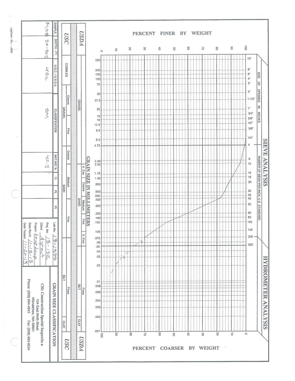
38 B.1 Geotechnical Laboratory Testing Geotechnical laboratory tests were conducted on selected soil samples collected during the field exploration program. The tests performed and the procedures followed are outlined below. Grain Size Analysis (G) Grain size analysis was analyzed in accordance with ASTM D 422 on SPT soil samples collected from soil boring B-1, and stream bank and channel grab samples. The results of the tests are presented as curves on Figures B-1 and B-9, plotting percent finer by weight versus grain size. Water Content Determination Water contents were determined in accordance with ASTM D 422 on SPT soil samples collected from soil boring B-1, and stream bank and channel grab samples in general accordance with ASTM D The results of the tests are presented on the boring log Figure A-2. Atterberg Limits Atterberg Limits (plasticity) were determined in accordance with ASTM D4318 on one fine-grained SPT soil sample (S-10) collected from soil boring B-1. The result of the test is shown on Figure B-10. Organic Content Determination Organic content determination was completed in accordance AASHTO T276 on one SPT soil sample (S-10) collect from soil boring B-1. The results of the test is shown on Figure B-11. PROJECT NO MAY 15, 2014 B-1
39
40 CSI: Construction Special Inspection MATERIALS TESTING & SPECIAL INSPECTION 104 East Ninth Street Wenatchee, WA (509) SOIL CLASSIFICATION SIEVE ANALYSIS ASTM D-422 & D-2487 CLIENT: Aspect LAB NO: PROJECT NO: DATE RCVD: 11/18/2013 PROJECT: Loup Loup Bridge DATE TESTED: 11/20/2013 CONTRACTOR: N/A SUBMITTED BY: Nick Szot SAMPLE LOCATION: B-1, S-1 SAMPLE DEPTH: SAMPLE DESC.: Well Graded Sand W/Silt (SW-SM) SIEVE SIZE (in.) SIEVE SIZE (mm) ACC. WEIGHT RETAINED (grams) PERCENT MATERIAL RETAINED PERCENT MATERIAL PASSING SPECIFICATION REQUIRED MATERIAL DESCRIPTION 4" COBBLES 3" COBBLES 2 1/2" COARSE GRAVEL 2" COARSE GRAVEL 1-1/2" COARSE GRAVEL 1" COARSE GRAVEL 3/4" COARSE GRAVEL 5/8" COARSE GRAVEL 1/2" FINE GRAVEL 3/8" FINE GRAVEL 1/4" 6.40 FINE GRAVEL No FINE GRAVEL No COARSE SAND No COARSE SAND No COARSE SAND No um MEDIUM SAND No um MEDIUM SAND No um MEDIUM SAND No um MEDIUM SAND No um FINE SAND No um FINE SAND No um FINE SAND No um FINE SAND No um FINE SAND No um SILT TOTAL PERCENT MOISTURE: 16.3% % REMARKS: TECHNICIAN: R. GILL PROJ. MGR. J.HILLS ClassSieve Rev'd
41
42 CSI: Construction Special Inspection MATERIALS TESTING & SPECIAL INSPECTION 104 East Ninth Street Wenatchee, WA (509) SOIL CLASSIFICATION SIEVE ANALYSIS ASTM D-422 & D-2487 CLIENT: Aspect LAB NO: PROJECT NO: DATE RCVD: 11/18/2013 PROJECT: Loup Loup Bridge DATE TESTED: 11/20/2013 CONTRACTOR: N/A SUBMITTED BY: Nick Szot SAMPLE LOCATION: B-1, S-4 SAMPLE DEPTH: SAMPLE DESC.: Silty Sand (SM) SIEVE SIZE (in.) SIEVE SIZE (mm) ACC. WEIGHT RETAINED (grams) PERCENT MATERIAL RETAINED PERCENT MATERIAL PASSING SPECIFICATION REQUIRED MATERIAL DESCRIPTION 4" COBBLES 3" COBBLES 2 1/2" COARSE GRAVEL 2" COARSE GRAVEL 1-1/2" COARSE GRAVEL 1" COARSE GRAVEL 3/4" COARSE GRAVEL 5/8" COARSE GRAVEL 1/2" FINE GRAVEL 3/8" FINE GRAVEL 1/4" 6.40 FINE GRAVEL No FINE GRAVEL No COARSE SAND No COARSE SAND No COARSE SAND No um MEDIUM SAND No um MEDIUM SAND No um MEDIUM SAND No um MEDIUM SAND No um FINE SAND No um FINE SAND No um FINE SAND No um FINE SAND No um FINE SAND No um SILT TOTAL PERCENT MOISTURE: 16.2% % REMARKS: TECHNICIAN: R. GILL PROJ. MGR. J.HILLS ClassSieve Rev'd
43
44 CSI: Construction Special Inspection MATERIALS TESTING & SPECIAL INSPECTION 104 East Ninth Street Wenatchee, WA (509) SOIL CLASSIFICATION SIEVE ANALYSIS ASTM D-422 & D-2487 CLIENT: Aspect LAB NO: PROJECT NO: DATE RCVD: 11/18/2013 PROJECT: Loup Loup Bridge DATE TESTED: 11/20/2013 CONTRACTOR: N/A SUBMITTED BY: Nick Szot SAMPLE LOCATION: B-1, S-8 SAMPLE DEPTH: SAMPLE DESC.: Silty Sand (SM) SIEVE SIZE (in.) SIEVE SIZE (mm) ACC. WEIGHT RETAINED (grams) PERCENT MATERIAL RETAINED PERCENT MATERIAL PASSING SPECIFICATION REQUIRED MATERIAL DESCRIPTION 4" COBBLES 3" COBBLES 2 1/2" COARSE GRAVEL 2" COARSE GRAVEL 1-1/2" COARSE GRAVEL 1" COARSE GRAVEL 3/4" COARSE GRAVEL 5/8" COARSE GRAVEL 1/2" FINE GRAVEL 3/8" FINE GRAVEL 1/4" 6.40 FINE GRAVEL No FINE GRAVEL No COARSE SAND No COARSE SAND No COARSE SAND No um MEDIUM SAND No um MEDIUM SAND No um MEDIUM SAND No um MEDIUM SAND No um FINE SAND No um FINE SAND No um FINE SAND No um FINE SAND No um FINE SAND No um SILT TOTAL PERCENT MOISTURE: 42.5% % REMARKS: Organic rich - Assume fines as ML TECHNICIAN: R. GILL PROJ. MGR. J.HILLS ClassSieve Rev'd

45
June 9, R. D. Cook, P.Eng. Soils Engineer Special Services Western Region PUBLIC WORKS CANADA WESTERN REGION REPORT ON
 PUBLIC WORKS CANADA WESTERN REGION REPORT ON GEOTECHNICAL INVESTIGATION PROPOSED MARTIN RIVER BRIDGE MILE 306.7 MACKENZIE HIGHWAY Submitted by : R. D. Cook, P.Eng. Soils Engineer Special Services Western
Date: April 2, 2014 Project No.: Prepared For: Mr. Adam Kates CLASSIC COMMUNITIES 1068 E. Meadow Circle Palo Alto, California 94303
 City of Newark - 36120 Ruschin Drive Project Draft Initial Study/Mitigated Negative Declaration Appendix C: Geologic Information FirstCarbon Solutions H:\Client (PN-JN)\4554\45540001\ISMND\45540001 36120
Liquefaction and Foundations
 Liquefaction and Foundations Amit Prashant Indian Institute of Technology Gandhinagar Short Course on Seismic Design of Reinforced Concrete Buildings 26 30 November, 2012 What is Liquefaction? Liquefaction
ATTACHMENT A PRELIMINARY GEOTECHNICAL SUMMARY
 ATTACHMENT A PRELIMINARY GEOTECHNICAL SUMMARY Kevin M. Martin, P.E. KMM Geotechnical Consultants, LLC 7 Marshall Road Hampstead, NH 0384 603-489-6 (p)/ 603-489-8 (f)/78-78-4084(m) kevinmartinpe@aol.com
Civil Engineering, Surveying and Environmental Consulting WASP0059.ltr.JLS.Mich Ave Bridge Geotech.docx
 2365 Haggerty Road South * Canton, Michigan 48188 P: 734-397-3100 * F: 734-397-3131 * www.manniksmithgroup.com August 29, 2012 Mr. Richard Kent Washtenaw County Parks and Recreation Commission 2330 Platt
KDOT Geotechnical Manual Edition. Table of Contents
 KDOT Geotechnical Manual 2007 Edition The KDOT Geotechnical Manual is available two volumes. Both volumes are very large electronic (pdf) files which may take several minutes to download. The table of
Mitigation of Liquefaction Potential Using Rammed Aggregate Piers
 ASCE 2011 557 Mitigation of Liquefaction Potential Using Rammed Aggregate Piers R.W. Rudolph, M. ASCE, G.E. 1, B. Serna, M. ASCE, P.E. 2, and T. Farrell, M. ASCE, G.E. 3 1 Principal Consultant, ENGEO,
IV. ENVIRONMENTAL IMPACT ANALYSIS G. GEOLOGY AND SOILS
 IV. ENVIRONMENTAL IMPACT ANALYSIS G. GEOLOGY AND SOILS The following section is a summary of the geotechnical report conducted for the proposed project. The Report of Geotechnical Investigation Proposed
(THIS IS ONLY A SAMPLE REPORT OR APPENDIX OFFERED TO THE USERS OF THE COMPUTER PROGRAM
 C A U T I O N!! (THIS IS ONLY A SAMPLE REPORT OR APPENDIX OFFERED TO THE USERS OF THE COMPUTER PROGRAM EQLique&Settle2. THE AUTHOR IS HEREBY RELEASED OF ANY LIABILITY FOR ANY INCORRECT USE OF THIS SAMPLE
SLOPE STABILITY EVALUATION AND ACCEPTANCE STANDARDS
 INFORMATION BULLETIN / PUBLIC - BUILDING CODE REFERENCE NO.: LABC 7006.3, 7014.1 Effective: 01-01-2017 DOCUMENT NO.: P/BC 2017-049 Revised: 12-21-2016 Previously Issued As: P/BC 2014-049 SLOPE STABILITY
Pierce County Department of Planning and Land Services Development Engineering Section
 Page 1 of 7 Pierce County Department of Planning and Land Services Development Engineering Section PROJECT NAME: DATE: APPLICATION NO.: PCDE NO.: LANDSLIDE HAZARD AREA (LHA) GEOLOGICAL ASSESSMENT REPORT
10. GEOTECHNICAL EXPLORATION PROGRAM
 Geotechnical site investigations should be conducted in multiple phases to obtain data for use during the planning and design of the tunnel system. Geotechnical investigations typically are performed in
Geotechnical Engineering Study, Conifer Senior High School Football Field Improvements, Conifer, Colorado
 2390 South Lipan Street Denver, CO 80223 phone: (303) 742-9700 fax: (303) 742-9666 email: kadenver@kumarusa.com www.kumarusa.com Office Locations: Denver (HQ), Colorado Springs, Fort Collins, and Frisco,
Preliminary Geotechnical Evaluation Gooseberry Point Pedestrian Improvements Whatcom County, Washington SITE AND PROJECT DESCRIPTION
 File No. 12-100 Geotechnical & Earthquake Engineering Consultants Mr. Kevin Brown, P.E. Gray & Osborne, Inc. 3710 168 th Street NE, Suite B210 Arlington, Washington 98223 Subject: Draft Report Preliminary
 R-1 Conveyor Relocation Project Legend 0 500 1000 1500 ft. This map is a user generated static output from an Internet mapping site and is for general reference only. Data layers that appear on this map
INTRODUCTION TO STATIC ANALYSIS PDPI 2013
 INTRODUCTION TO STATIC ANALYSIS PDPI 2013 What is Pile Capacity? When we load a pile until IT Fails what is IT Strength Considerations Two Failure Modes 1. Pile structural failure controlled by allowable
SLOPE STABILITY EVALUATION AND ACCEPTANCE STANDARDS
 INFORMATION BULLETIN / PUBLIC - BUILDING CODE REFERENCE NO.: LAMC 98.0508 Effective: 1-26-84 DOCUMENT NO. P/BC 2002-049 Revised: 11-1-02 Previously Issued As: RGA #1-84 SLOPE STABILITY EVALUATION AND ACCEPTANCE
CHAPTER GEOLOGICALLY HAZARDOUS AREAS Applicability Regulations.
 CHAPTER 19.07 GEOLOGICALLY HAZARDOUS AREAS 19.07.010 Applicability. Geologically hazardous areas may pose a threat to the health and safety of citizens when incompatible development is sited in areas of
14 Geotechnical Hazards
 Volume 2: Assessment of Environmental Effects 296 14 Geotechnical Hazards Overview This Chapter provides an assessment of the underlying geotechnical conditions to identify: any potential liquefaction
Impact : Changes to Existing Topography (Less than Significant)
") 4.2 Land Resources 4.2.1 Alternative A Proposed Action Impact 4.2.1-1: Changes to Existing Topography (Less than Significant) Development of the project site would involve grading and other earthwork as
4.2 Land Resources 4.2.1 Alternative A Proposed Action Impact 4.2.1-1: Changes to Existing Topography (Less than Significant) Development of the project site would involve grading and other earthwork as
Geotechnical Aspects of the Seismic Update to the ODOT Bridge Design Manual. Stuart Edwards, P.E Geotechnical Consultant Workshop
 Geotechnical Aspects of the Seismic Update to the ODOT Bridge Design Manual Stuart Edwards, P.E. 2017 Geotechnical Consultant Workshop Changes Role of Geotechnical Engineer Background Methodology Worked
R.M.HARW & ASSOCIATES LTD. GEOTECHNICAL INVESTIGATION PROPOSED BRIDGE SITE. HELAVA CREEKl MILE MACKENZIE HIGHWAY E-2510 OCTOBER 16, 1973
 El R.M.HARW & ASSOCIATES LTD. GEOTECHNICAL INVESTIGATION PROPOSED BRIDGE SITE HELAVA CREEKl MILE 616.4 MACKENZIE HIGHWAY E-2510 OCTOBER 16, 1973 R,M,HARDV & ASSOCIATES LTD. CONSULTING ENGINEERING & TESTING
3.12 Geology and Topography Affected Environment
 3 Affected Environment and Environmental Consequences 3.12 Geology and Topography 3.12.1 Affected Environment 3.12.1.1 Earthquakes Sterling Highway MP 45 60 Project Draft SEIS The Kenai Peninsula is predisposed
APPENDIX E SOILS TEST REPORTS
 Otsego County, NY Site Work Specifications APPENDIX E SOILS TEST REPORTS Blue Wing Services, Inc. July 1, 2010 Blue Wing Services May 20, 2010 Page 2 the site, was not made available to Empire at this
Geotechnical Investigation Juneau Seawalk - Taku Fisheries to Miner s Wharf Juneau, Alaska DM&A Job No
 Duane Miller & Associates 5821 Arctic Boulevard, Suite A Anchorage, AK 99518-1654 (907) 644-3200 Fax 644-0507 Arctic & Geotechnical Engineering May 4, 2006 Tetra Tech/KCM, Inc. 1971 First Avenue Seattle,
Guidelines for Site-Specific Seismic Hazard Reports for Essential and Hazardous Facilities and Major and Special-Occupancy Structures in Oregon
 Guidelines for Site-Specific Seismic Hazard Reports for Essential and Hazardous Facilities and Major and Special-Occupancy Structures in Oregon By the Oregon Board of Geologist Examiners and the Oregon
3.18 GEOLOGY AND SOILS
 3.18 GEOLOGY AND SOILS This section discusses geologic resource concerns as they relate to the environment, public safety, and project design both during construction and after completion of the project.
Limited Geotechnical Engineering Evaluation Classroom Additions Albany County Campus Laramie, Wyoming
 Limited Geotechnical Engineering Evaluation Classroom Additions Albany County Campus 2300 Missile Drive, Cheyenne, Wyoming 82001 Phone 307-635-0222 www.stratageotech.com Limited Geotechnical Engineering
In-class Exercise. Problem: Select load factors for the Strength I and Service I Limit States for the. Loading Diagram for Student Exercise
 In-class Exercise Problem: Select load factors for the Strength I and Service I Limit States for the problem illustrated below. Loading Diagram for Student Exercise For this exercise, complete the following
B-1 BORE LOCATION PLAN. EXHIBIT Drawn By: 115G BROOKS VETERINARY CLINIC CITY BASE LANDING AND GOLIAD ROAD SAN ANTONIO, TEXAS.
 N B-1 SYMBOLS: Exploratory Boring Location Project Mngr: BORE LOCATION PLAN Project No. GK EXHIBIT Drawn By: 115G1063.02 GK Scale: Checked By: 1045 Central Parkway North, Suite 103 San Antonio, Texas 78232
ENCE 3610 Soil Mechanics. Site Exploration and Characterisation Field Exploration Methods
 ENCE 3610 Soil Mechanics Site Exploration and Characterisation Field Exploration Methods Geotechnical Involvement in Project Phases Planning Design Alternatives Preparation of Detailed Plans Final Design
TABLE OF CONTENTS. 1.0 INTRODUCTION Purpose Scope of Work PROJECT LOCATION AND DESCRIPTION...1
 TABLE OF CONTENTS Page 1. INTRODUCTION...1 1.1 Purpose...1 1.2 Scope of Work...1 2. PROJECT LOCATION AND DESCRIPTION...1 3. EXISTING BRIDGE STRUCTURE AND PROPOSED IMPROVEMENTS...2 4. EXPLORATIONS AND LABORATORY
Earth Mechanics, Inc. Geotechnical & Earthquake Engineering
 TECHNICAL MEMORANDUM EMI PROJECT NO: 13-116 DATE: October 29, 2013 PREPARED FOR: Mr. Todd W. Dudley / AECOM PREPARED BY: SUBJECT: (Raja) S. Pirathiviraj and Lino Cheang / (EMI) Preliminary Foundation Report
Geotechnical Engineering Report
 Geotechnical Engineering Report Turner Turnpike Widening Bridge B Bridge Crossing: South 257 th West Avenue Creek County, Oklahoma June 1, 2016 Terracon Project No. 04155197 Prepared for: Garver, LLC Tulsa,
STRUCTURAL STABILITY ASSESSMENT
 STRUCTURAL STABILITY ASSESSMENT CFR 257.73(d) Bottom Ash Pond Complex Cardinal Plant Brilliant, Ohio October, 2016 Prepared for: Cardinal Operating Company Cardinal Plant Brilliant, Ohio Prepared by: Geotechnical
SHEET PILE WALLS. Mehdi Mokhberi Islamic Azad University
 SHEET PILE WALLS Mehdi Mokhberi Islamic Azad University Lateral Support In geotechnical engineering, it is often necessary to prevent lateral soil movements. Tie rod Anchor Sheet pile Cantilever retaining
Deep Foundations 2. Load Capacity of a Single Pile
 Deep Foundations 2 Load Capacity of a Single Pile All calculations of pile capacity are approximate because it is almost impossible to account for the variability of soil types and the differences in the
M E M O R A N D U M. Mr. Jonathan K. Thrasher, P.E., Mr. Ian Kinnear, P.E. (FL) PSI
 PSI") M E M O R A N D U M TO: FROM: Mr. Mark Schilling Gulf Interstate Engineering Mr. Jonathan K. Thrasher, P.E., Mr. Ian Kinnear, P.E. (FL) PSI DATE: November 11, 2014 RE: Summary of Findings Geotechnical
M E M O R A N D U M TO: FROM: Mr. Mark Schilling Gulf Interstate Engineering Mr. Jonathan K. Thrasher, P.E., Mr. Ian Kinnear, P.E. (FL) PSI DATE: November 11, 2014 RE: Summary of Findings Geotechnical
Numerical analysis of effect of mitigation measures on seismic performance of a liquefiable tailings dam foundation
 Numerical analysis of effect of mitigation measures on seismic performance of a liquefiable tailings dam foundation Yong-Beom Lee, Jorge Castillo Ausenco, USA Aurelian C. Trandafir Fugro GeoConsulting
Boreholes. Implementation. Boring. Boreholes may be excavated by one of these methods: 1. Auger Boring 2. Wash Boring 3.
 Implementation Boreholes 1. Auger Boring 2. Wash Boring 3. Rotary Drilling Boring Boreholes may be excavated by one of these methods: 4. Percussion Drilling The right choice of method depends on: Ground
SITE INVESTIGATION 1
 SITE INVESTIGATION 1 Definition The process of determining the layers of natural soil deposits that will underlie a proposed structure and their physical properties is generally referred to as site investigation.
Neutral Plane Method for Drag Force of Deep Foundations and the AASHTO LRFD Bridge Design Specifications
 Neutral Plane Method for Drag Force of Deep Foundations and the AASHTO LRFD Bridge Design Specifications Timothy C. Siegel, P.E., G.E., D.GE Dan Brown and Associates, PC, Knoxville, Tennessee USA Rich
An Introduction to Field Explorations for Foundations
 An Introduction to Field Explorations for Foundations J. Paul Guyer, P.E., R.A. Paul Guyer is a registered mechanical engineer, civil engineer, fire protection engineer and architect with over 35 years
DATA REPORT GEOTECHNICAL INVESTIGATION GALVESTON CRUISE TERMINAL 2 GALVESTON, TEXAS
 DATA REPORT GEOTECHNICAL INVESTIGATION GALVESTON CRUISE TERMINAL 2 GALVESTON, TEXAS SUBMITTED TO PORT OF GALVESTON 123 ROSENBERG AVENUE, 8TH FLOOR GALVESTON, TEXAS 77553 BY HVJ ASSOCIATES, INC. HOUSTON,
IV. ENVIRONMENTAL IMPACT ANALYSIS E. GEOLOGY AND SOILS
 IV. ENVIRONMENTAL IMPACT ANALYSIS E. GEOLOGY AND SOILS The following analysis is based on the Geotechnical Investigation Report, Proposed Mid-Rise Multi- Family Residential Development Project Wetherly
Northern Colorado Geotech
 PRELIMINARY GEOTECHNICAL ENGINEERING REPORT PROPOSED CECIL FARMS DEVELOPMENT WELD COUNTY ROAD 7, BETWEEN ROADS 7 AND 7 SEVERANCE, COLORADO NORTHERN COLORADO GEOTECH PROJECT NO. 0-6 APRIL 0, 06 Prepared
Slope Stability Evaluation Ground Anchor Construction Area White Point Landslide San Pedro District Los Angeles, California.
 Slope Stability Evaluation Ground Anchor Construction Area White Point Landslide San Pedro District Los Angeles, California Submitted To: Mr. Gene Edwards City of Los Angeles Department of Public Works
FIFTH STREET GRADE SEPARATION CARSON CITY, NEVADA
 GEOTECHNICAL REPORT FIFTH STREET GRADE SEPARATION CARSON CITY, NEVADA JULY 2005 MATERIALS DIVISION STATE OF NEVADA DEPARTMENT OF TRANSPORTATION MATERIALS DIVISION GEOTECHNICAL SECTION GEOTECHNICAL REPORT
SURFACE GEOLOGY AND LIQUEFACTION SUSCEPTIBILITY IN THE INNER RIO GRANDE VALLEY NEAR ALBUQUERQUE, NEW MEXICO
 SURFACE GEOLOGY AND LIQUEFACTION SUSCEPTIBILITY IN THE INNER RIO GRANDE VALLEY NEAR ALBUQUERQUE, NEW MEXICO Keith I. Kelson, Christopher S. Hitchcock, and Carolyn E. Randolph William Lettis & Associates,
S E C T I O N 1 2 P R O D U C T S E L E C T I O N G U I D E - H E L I C A L S C R E W P I L E F O U N D A T I O N S
 1. P R O D U C T S E L E C T I O N G U I D E - H E L I C A L S C R E W P I L E F O U N D A T I O N S Helical foundation pile includes a lead and extension(s). The lead section is made of a central steel
Horizontal Directional Drilling: An Approach to Design and Construction. Presenter: John Briand, PE Co-Author: Danielle Neamtu, PE
 Horizontal Directional Drilling: An Approach to Design and Construction Presenter: John Briand, PE Co-Author: Danielle Neamtu, PE Presentation Outline General HDD overview Conceptual-level evaluation Detailed
IV. ENVIRONMENTAL IMPACT ANALYSIS E. GEOLOGY AND SOILS
 IV. ENVIRONMENTAL IMPACT ANALYSIS E. GEOLOGY AND SOILS The following section is a summary of the geotechnical report conducted for the Proposed Project. The Geotechnical Engineering Investigation (the
Converse Consultants Geotechnical Engineering, Environmental & Groundwater Science, Inspection & Testing Services
 Converse Consultants Geotechnical Engineering, Environmental & Groundwater Science, Inspection & Testing Services Ms. Rebecca Mitchell Mt. San Antonio College Facilities Planning & Management 1100 North
Liquefaction Induced Negative Skin Friction from Blast-induced Liquefaction Tests with Auger-cast Piles
 6 th International Conference on Earthquake Geotechnical Engineering 1-4 November 2015 Christchurch, New Zealand Liquefaction Induced Negative Skin Friction from Blast-induced Liquefaction Tests with Auger-cast
 Photo 1 - Southerly view across 2700 parking lot toward existing building. Multi-residential building borders western side of property in upper right of view. Photo 2 - Southerly view across 2750 parking
CITY OF CAPE CORAL NORTH 2 UTILITIES EXTENSION PROJECT CONTRACT 3
 GEOTECHNICAL REPORT CITY OF CAPE CORAL NORTH UTILITIES EXTENSION PROJECT CONTRACT City of Cape Coral Procurement Division Cultural Park Boulevard, nd Floor Cape Coral, FL ISSUED FOR BID VOLUME of GEOTECHNICAL
LIQUEFACTION OF EARTH EMBANKMENT DAMS TWO CASE HISTORIES: (1) LIQUEFACTION OF THE EMBANKMENT SOILS, AND (2) LIQUEFACTION OF THE FOUNDATIONS SOILS
 LIQUEFACTION OF THE EMBANKMENT SOILS, AND (2) LIQUEFACTION OF THE FOUNDATIONS SOILS") LIQUEFACTION OF EARTH EMBANKMENT DAMS TWO CASE HISTORIES: (1) LIQUEFACTION OF THE EMBANKMENT SOILS, AND (2) LIQUEFACTION OF THE FOUNDATIONS SOILS Antonio Fernandez, Ph.D. 1 ABSTRACT Paul C. Rizzo Associates,
LIQUEFACTION OF EARTH EMBANKMENT DAMS TWO CASE HISTORIES: (1) LIQUEFACTION OF THE EMBANKMENT SOILS, AND (2) LIQUEFACTION OF THE FOUNDATIONS SOILS Antonio Fernandez, Ph.D. 1 ABSTRACT Paul C. Rizzo Associates,
Downtown Anchorage Seismic Risk Assessment & Land Use Regulations to Mitigate Seismic Risk
 Prepared for: The Municipality of Anchorage Planning Department and the Geotechnical Advisory Commission Downtown Anchorage Seismic Risk Assessment & Land Use Regulations to Mitigate Seismic Risk Prepared
December 5, Junction Gateway, LLC 7551 W. Sunset Boulevard #203 Los Angeles, CA Mr. James Frost P: Dear Mr.
 December 5, 2014 Junction Gateway, LLC 7551 W. Sunset Boulevard #203 90046 Attn: Re: Mr. James Frost P: 323.883.1800 Geotechnical Update Letter Sunset & Effie Mixed Use Development 4301 to 4311 Sunset
J. Paul Guyer, P.E., R.A.
 J. Paul Guyer, P.E., R.A. Paul Guyer is a registered mechanical engineer, civil engineer, fire protection engineer and architect with over 35 years experience in the design of buildings and related infrastructure.
GEOTECHNICAL ENGINEERING II. Subject Code : 06CV64 Internal Assessment Marks : 25 PART A UNIT 1
 GEOTECHNICAL ENGINEERING II Subject Code : 06CV64 Internal Assessment Marks : 25 PART A UNIT 1 1. SUBSURFACE EXPLORATION 1.1 Importance, Exploration Program 1.2 Methods of exploration, Boring, Sounding
GEOTECHNICAL REPORT CBSA Facility Redevelopment Thousand Islands International Crossing Lansdowne, Ontario
 GEOTECHNICAL REPORT CBSA Facility Redevelopment Thousand Islands International Crossing Lansdowne, Ontario Prepared For: The Federal Bridge Corporation Limited SPL Project No.: 10001084 Report Date: January
Case Study - Undisturbed Sampling, Cyclic Testing and Numerical Modelling of a Low Plasticity Silt
 6 th International Conference on Earthquake Geotechnical Engineering 1-4 November 2015 Christchurch, New Zealand Case Study - Undisturbed Sampling, Cyclic Testing and Numerical Modelling of a Low Plasticity
3.0 SUMMARY OF POTENTIAL GEOTECHNICAL IMPACTS AND MITIGATION MEASURES
 3.0 SUMMARY OF POTENTIAL GEOTECHNICAL IMPACTS AND MITIGATION MEASURES This section summarizes the principal geotechnical conditions that occur in the project area. The potential impact that each condition
GEOTECHNICAL REPORT. Matanuska-Susitna Borough. Parks Highway Connections Museum Drive. Matanuska-Susitna Borough, Alaska.
 Matanuska-Susitna Borough GEOTECHNICAL REPORT Parks Highway Connections Museum Drive Matanuska-Susitna Borough, Alaska March 2, 20 Prepared By: John Thornley, PE Geotechnical Engineer 333 Arctic Blvd.,
Liquefaction assessments of tailings facilities in low-seismic areas
 Page 1 Liquefaction assessments of tailings facilities in low-seismic areas Holly Rourke SRK Consulting, Perth, WA, Australia Caroline Holmes SRK Consulting, Perth, WA, Australia This paper was first presented
Chapter 12 Subsurface Exploration
 Page 12 1 Chapter 12 Subsurface Exploration 1. The process of identifying the layers of deposits that underlie a proposed structure and their physical characteristics is generally referred to as (a) subsurface
Case History of Observed Liquefaction-Induced Settlement Versus Predicted Settlement
 Case History of Observed Liquefaction-Induced Settlement Versus Predicted Settlement M. Lew and L. Tran AMEC Environment & Infrastructure, Inc., Los Angeles, CA USA SUMMARY: A comparison of the predicted
GEOLOGY, SOILS, AND SEISMICITY
 4.9 GEOLOGY, SOILS, AND SEISMICITY 4.9.1 Introduction Information about the geological conditions and seismic hazards in the study area was summarized in the FEIR, and was based on the Geotechnical Exploration
Geotechnical Engineering Report
 Geotechnical Engineering Report Turner Turnpike Widening Bridge D Bridge Crossing: South 209 th West Avenue Creek County, Oklahoma June 1, 2016 Terracon Project No. 04155197 Prepared for: Garver, LLC Tulsa,
IN SITU SPECIFIC GRAVITY VS GRAIN SIZE: A BETTER METHOD TO ESTIMATE NEW WORK DREDGING PRODUCTION
 IN SITU SPECIFIC GRAVITY VS GRAIN SIZE: A BETTER METHOD TO ESTIMATE NEW WORK DREDGING PRODUCTION Nancy Case O Bourke, PE 1, Gregory L. Hartman, PE 2 and Paul Fuglevand, PE 3 ABSTRACT In-situ specific gravity
Seismic Design of a Hydraulic Fill Dam by Nonlinear Time History Method
 Seismic Design of a Hydraulic Fill Dam by Nonlinear Time History Method E. Yıldız & A.F. Gürdil Temelsu International Engineering Services Inc., Ankara, Turkey SUMMARY: Time history analyses conducted
APPENDICES. Appendix A City Standard Details Appendix B Engineering Geology Report
 APPENDICES Appendix A City Standard Details Appendix B Engineering Geology Report APPENDIX A CITY STANDARDS DETAILS APPENDIX B ENGINEERING GEOLOGY REPORT ENGINEERING GEOLOGY REPORT WATER
GEOTECHNICAL STUDY REPORT PROPOSED WATER STORAGE TANK WATER SYSTEM IMPROVEMENT WALNUT GROVE, CALIFORNIA. Prepared for: MWH AMERICAS INC.
 GEOTECHNICAL STUDY REPORT PROPOSED WATER STORAGE TANK WATER SYSTEM IMPROVEMENT WALNUT GROVE, CALIFORNIA Prepared for: MWH AMERICAS INC Prepared by: NOVEMBER 2012 GEOTECHNICAL STUDY REPORT PROPOSED WATER
LRFD GEOTECHNICAL IMPLEMENTATION
 LRFD GEOTECHNICAL IMPLEMENTATION Ching-Nien Tsai, P.E. LADOTD Pavement and Geotechnical Services In Conjunction with LTRC WHY LRFD FHWA deadline - October 2007 LRFD is a better method Risk is quantified
Lesson 25. Static Pile Load Testing, O-cell, and Statnamic. Reference Manual Chapter 18
 Lesson 25 Static Pile Load Testing, O-cell, and Statnamic Reference Manual Chapter 18 STATIC LOAD TESTING Most accurate method to determine static pile capacity Perform at design or construction stage
FINAL GEOTECHNICAL INVESTIGATION BURNS BRIDGE REPLACEMENT COLORADO RIVER ROAD BURNS, COLORADO. December 12, 2012
 FINAL GEOTECHNICAL INVESTIGATION BURNS BRIDGE REPLACEMENT COLORADO RIVER ROAD BURNS, COLORADO December 12, 2012 Prepared For: AMEC Environment & Infrastructure 2000 South Colorado Boulevard, Suite 21000
Geotechnical Engineering Report
 Geotechnical Engineering Report Turner Turnpike Widening Polecat Creek Bridge (Bridge A) June 1, 2016 Terracon Project No. 04155197 Prepared for: Garver, LLC Prepared by: Terracon Consultants, Inc. TABLE
IAEA SAFETY STANDARDS Geotechnical Aspects of Site Evaluation and Foundations in NPPs, NS-G-3.6
 IAEA SAFETY STANDARDS Geotechnical Aspects of Site Evaluation and Foundations in NPPs, NS-G-3.6 Regional Workshop on Volcanic, Seismic, and Tsunami Hazard Assessment Related to NPP Siting Activities and
Landslide FE Stability Analysis
 Landslide FE Stability Analysis L. Kellezi Dept. of Geotechnical Engineering, GEO-Danish Geotechnical Institute, Denmark S. Allkja Altea & Geostudio 2000, Albania P. B. Hansen Dept. of Geotechnical Engineering,
Geotechnical issues in seismic assessments: When do I need a geotechnical specialist?
 Geotechnical issues in seismic assessments: When do I need a geotechnical specialist? B.H. Rama & S.J. Palmer Tonkin & Taylor Ltd (T+T), Wellington, New Zealand. 2016 NZSEE Conference ABSTRACT: The Canterbury
Gotechnical Investigations and Sampling
 Gotechnical Investigations and Sampling Amit Prashant Indian Institute of Technology Gandhinagar Short Course on Geotechnical Investigations for Structural Engineering 12 14 October, 2017 1 Purpose of
INTI COLLEGE MALAYSIA
 EGC373 (F) / Page 1 of 5 INTI COLLEGE MALAYSIA UK DEGREE TRANSFER PROGRAMME INTI ADELAIDE TRANSFER PROGRAMME EGC 373: FOUNDATION ENGINEERING FINAL EXAMINATION : AUGUST 00 SESSION This paper consists of
B-1 SURFACE ELEVATION
 5A 5B LOGGED BY El. S. Bhangoo DRILLING CONTRACTOR Pitcher Drilling DRILLING METHOD Rotary Wash BEGIN DATE 12-14-12 SAMPLER TYPE(S) AND SIZE(S) (ID) SPT, MC BOREHOLE BACKFILL AND COMPLETION COMPLETION
CENTRAL REGION GEOHAZARDS RISK ASSESSMENT SITE INSPECTION FORM
 SITE NUMBER AND NAME C55 H861:02 Slide LEGAL DESCRIPTION NW 14-40-14-W4 CENTRAL REGION GEOHAZARDS RISK ASSESSMENT SITE INSPECTION FORM HIGHWAY & KM NAD 83 COORDINATES N 5811217 E 437291 PREVIOUS INSPECTION
Manual on Subsurface Investigations National Highway Institute Publication No. FHWA NHI Federal Highway Administration Washington, DC
 Manual on Subsurface Investigations National Highway Institute Publication No. FHWA NHI-01-031 Federal Highway Administration Washington, DC Geotechnical Site Characterization July 2001 by Paul W. Mayne,
Role of the Geotechnical Consultant in Design Build Projects a General Contractors Geotechnical Engineer s Perspective
 Role of the Geotechnical Consultant in Design Build Projects a General Contractors Geotechnical Engineer s Perspective Steven R. Saye Kiewit Engineering Group, Inc. Design Build Geotechnical Goal All parties
Hydrogeological Assessment for Part of Lots 2 and 3, Concession 5, Township of Thurlow, County of Hastings 1.0 INTRODUCTION. 1.
 February 10,2017 25506400 Ontario Ltd. Foxboro, ON Attention: Brad Newbatt Re: Hydrogeological Assessment for Part of Lots 2 and 3, Concession 5, Township of Thurlow, County of Hastings 1.0 INTRODUCTION
REPORT OF PRELIMINARY GEOTECHNICAL EXPLORATION
 REPORT OF PRELIMINARY GEOTECHNICAL EXPLORATION ENKA INTERMEDIATE SCHOOL Sand Hill Road Candler, North Carolina Prepared For: BUNCOMBE COUNTY SCHOOLS Prepared By: AMEC ENVIRONMENT & INFRASTRUCTURE, INC.
SOIL INVESTIGATION REPORT. PROPOSED HOUSING DEVELOPMENT PROJECT Coral Spring, Trelawny, Jamaica.
 SOIL INVESTIGATION REPORT PROPOSED HOUSING DEVELOPMENT PROJECT Coral Spring, Trelawny, Jamaica. Prepared for: FCS Consultants 7a Barbados Avenue Kingston 5, Jamaica Prepared by: NHL Engineering Limited
 Project: ITHACA-TOMPKINS REGIONAL AIRPORT EXPANSION Project Location: ITHACA, NY Project Number: 218-34 Key to Soil Symbols and Terms TERMS DESCRIBING CONSISTENCY OR CONDITION COARSE-GRAINED SOILS (major
Chapter 7 Mudflow Analysis
 Chapter 7 Mudflow Analysis 7.0 Introduction This chapter provides information on the potential and magnitude of mud floods and mudflows that may develop in Aspen due to rainfall events, snowmelt, or rain
Effective stress analysis of pile foundations in liquefiable soil
 Effective stress analysis of pile foundations in liquefiable soil H. J. Bowen, M. Cubrinovski University of Canterbury, Christchurch, New Zealand. M. E. Jacka Tonkin and Taylor Ltd., Christchurch, New
Guidelines on Foundation Loading and Deformation Due to Liquefaction Induced Lateral Spreading
 Guidelines on Foundation Loading and Deformation Due to Liquefaction Induced Lateral Spreading February, 2011 1 INTRODUCTION Past earthquakes offer many examples of bridges that either collapsed or incurred
Geotechnical Engineering Services
 Geotechnical Engineering Services Energize Eastside Phase II Project Redmond to Renton, Washington for Puget Sound Energy June 6, 2016 Geotechnical Engineering Services Energize Eastside Phase II Project
AGMU Memo Liquefaction Analysis
 LRFD Liquefaction Analysis This design guide illustrates the Department s recommended procedures for analyzing the liquefaction potential of soil during a seismic event considering Article 0.5.4.2 of the
Reinforced Soil Structures Reinforced Soil Walls. Prof K. Rajagopal Department of Civil Engineering IIT Madras, Chennai
 Geosynthetics and Reinforced Soil Structures Reinforced Soil Walls continued Prof K. Rajagopal Department of Civil Engineering IIT Madras, Chennai e-mail: gopalkr@iitm.ac.inac in Outline of the Lecture
APPENDIX F CORRELATION EQUATIONS. F 1 In-Situ Tests
 APPENDIX F 1 APPENDIX F CORRELATION EQUATIONS F 1 In-Situ Tests 1. SPT (1) Sand (Hatanaka and Uchida, 1996), = effective vertical stress = effective friction angle = atmosphere pressure (Shmertmann, 1975)
Geotechnical Engineering Report Iron Mountain Sanitary Sewer and Pedestrian Bridge Lake Oswego, Oregon. March 30, 2015
 Geotechnical Engineering Report Iron Mountain Sanitary Sewer and Pedestrian Bridge Lake Oswego, Oregon March 30, 2015 Geotechnical Engineering Report Iron Mountain Sanitary Sewer and Pedestrian Bridge
GEOTECHNICAL INVESTIGATION REPORT
 GEOTECHNICAL INVESTIGATION REPORT SOIL INVESTIGATION REPORT FOR STATIC TEST FACILITY FOR PROPELLANTS AT BDL, IBRAHIMPATNAM. Graphics Designers, M/s Architecture & Engineering 859, Banjara Avenue, Consultancy