SUMMARY REPORT ON GROUND INVESTIGATIONS AT WALSHESTOWN PIT CO. KILDARE. Submitted to:
|
|
|
- Charlene Adams
- 6 years ago
- Views:
Transcription
![Golder Associates Ireland Town Centre House, Dublin Road, Naas, Co. Kildare, Ireland Tel: [353] (0)45 874411 Fax: [353] (0)45 874549 E-mail: info@golder.](/docs-images/73/68171532/images/1-0.jpg "ie http://www.golder.com SUMMARY REPORT ON GROUND INVESTIGATIONS AT ALSHESTON PIT CO. KILDARE Submitted to: Mr Pierce Power Cemex (ROI) Ltd.")
1 Golder Associates Ireland Town Centre House, Dublin Road, Naas, Co. Kildare, Ireland Tel: [353] (0) Fax: [353] (0) SUMMARY REPORT ON GROUND INVESTIGATIONS AT ALSHESTON PIT CO. KILDARE Submitted to: Mr Pierce Power Cemex (ROI) Ltd. Block A1 East Point Business Park Dublin 3 DISTRIBUTION: 2 copies - Cemex (ROI) Ltd R01/V1 2 copies - Golder Associates OFFICES IN AFRICA, ASIA, AUSTRALIA, NE ZEAL, EUROPE, NORTH AMERICA, SOUTH AMERICA Company Registered in Ireland No At Trident House, Dublin Road, Naas, Co. Kildare, Ireland
2 October 2008 Cemex (ROI) Ltd R01/V1 Ground Investigation, alshestown REPORT ISSUE FORM Version Code A.0 Issue Date October 2008 Document Title Summary Report On Ground Investigations At alshestown Pit, Co. Kildare Comments List of Authors Client Client Reference Project Manager Approval Reviewer Pamela Keirns Cemex (ROI) Ltd. Conor all Barry Balding Report Name No. Copies Distribution Golder Associates Cemex (ROI) Ltd 2 2 Definition of Version Code: D. Applied during initial drafting of the report before it has been reviewed. C. Applied after the report has been reviewed but before it has been approved by the Project Manager. B. Applied after the Project Manager has approved the report ready for issue to the client. A. Applied to reports after external/client review. The version number starts at 0 and is raised by 1 at each re-type. Golder Associates
3 October i R01/V1 Cemex (ROI) Ltd A.0 Ground Investigation, alshestown TABLE OF CONTENTS SECTION PAGE 1.0 INTRODUCTION General SCOPE OF INVESTIGATIONS METHOD OF INVESTIGATION General Drilling in Soils Rotary Percussion indow Sampling Cable Percussion Drilling in Rock Geophysics (Resistivity) Survey of Borehole Locations and Geophysics Lines Laboratory Testing Slug Testing SUMMARY OF SUBSURFACE CONDITIONS General Soils Silt Lagoon Bedrock Groundwater Bedrock Soils REFERENCES Golder Associates
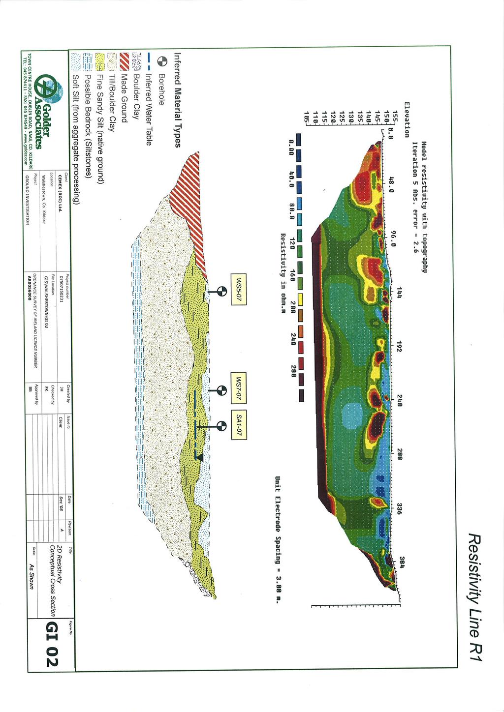
4 October ii R01/V1 Cemex (ROI) Ltd A.0 Ground Investigation, alshestown LIST OF FIGURES Figure GI/01 Location Plan for Ground Investigation Figure GI/02 2D Resistivity Conceptual Cross Section Figure GI/03 Inferred Groundwater Contours in Bedrock (15 February 2008) LIST OF TABLES Table 1 Table 2 Table 3 Table 4 Table 5 Table 6 Table 7 Table 8 Table 9 Record of borehole contractors and drilling methods Thickness of soils at Site & depth to waterstrike in rotary boreholes Summary of ground conditions encountered in rotary boreholes Estimated hydraulic conductivity of mineral soils and bedrock in the field Summary of window sample probes, shell & auger borehole and bulk samples Summary of results of laboratory tests on window samples Summary of results of laboratory tests on shell & auger and rotary borehole samples Summary of ground conditions encountered in former silt lagoon area Monitored groundwater levels (m AOD) LIST OF ATTACHMENTS Attachment A Attachment B Attachment C Borehole and Probe Logs Laboratory Testing Slug Testing Procedure Golder Associates
5 October 2008 ES R01/V1 Cemex (ROI) Ltd A.0 Ground Investigation, alshestown EXECUTIVE SUMMARY Cemex (ROI) Ltd (Cemex) has retained Golder Associates Ireland (Golder) to assess the possible risks posed to the groundwater and surface water environment by a proposed facility for disposal/recovery of inert materials at a worked-out sand and gravel site, at alshestown, Co Kildare. There are three large ponds on the Site, two along the western boundary (Ponds A1/A2 and A3) and one in the southern part of the Site (Pond B). The worked-out pit area has been restored to agricultural land-use (grazing) in the southern and eastern parts of the Site. The northern part of the Site is, for the most part exposed silts, with glacial till along part of the western boundary. The central area of the Site, almost as far south as Pond B, comprises made ground. The field investigation comprised eight rotary boreholes, one shell & auger borehole, nine window sample probes and one line of geophysics. A programme of laboratory testing was undertaken, which included classification testing of materials encountered. A piezometer was installed in each of the eight rotary boreholes to collect information on groundwater both upgradient and down-gradient of the proposed development. From interpretation of the site investigation data a number of observations can be made about the on-site sub-surface: (a) Recorded soil thickness ranges from ca.15 m to ca.38 m, and is typically greater than ca.22 m; (b) The mineral soils generally consisted of sandy gravelly silts (sometimes clays); (c) A zone of heavily weathered bedrock, ranging from between 2.5 m to 7.5 m thickness is interpreted to occur below the mineral soils; and (d) Thinly bedded grey-green siltstones lie below the heavily weathered zone. Groundwater flow direction is interpreted, from water level monitoring and contouring, to be towards west- northwest. Golder Associates
6 October R01/V1 Cemex (ROI) Ltd A.0 Ground Investigation, alshestown 1.0 INTRODUCTION 1.1 General Cemex (ROI) Ltd (Cemex) has retained Golder Associates Ireland (Golder) to assess the possible risks posed to the groundwater and surface water environment by a proposed facility for disposal/recovery of inert materials at a worked-out sand and gravel site, at alshestown, Co Kildare. The alshestown Pit is located at Irish National Grid co-ordinate ; c. 5 km southeast of Naas, Co. Kildare (approximately halfway between Naas and Blessington), and c. 0.5 km due east of Punchestown racecourse. The Site covers an area of c. 70 hectares. The southern and eastern parts of the Site have been restored to agricultural grazing land. The central and northern parts consist of bare made ground and a former silt lagoon area respectively (Figure GI/01) There are currently three large ponds on the Site, two along the western boundary (Ponds A1/A2 and A3) and one in the southern part of the Site (Pond B). The water level in the ponds fluctuates seasonally. The ground just south of Pond B is wet underfoot with scattered clumps of rushes, and remains damp throughout the year; in very wet weather the pond overflows at the southwestern corner. Golder carried out ground investigations to provide information on the geology, hydrogeological and geotechnical properties of the mineral soils and rock underlying the Site, in order to assist with the design of the proposed facility. The field investigations comprised eight rotary boreholes, one shell & auger borehole, nine window samples and one line of geophysics. A short programme of laboratory testing was undertaken that included classification testing on silts. Seven rotary boreholes were drilled on the expected upgradient and downgradient perimeters of the Site with respect to groundwater flow. One rotary borehole was drilled in a central location. The silt-lagoon area in the north of the Site was investigated by means of nine window sample probes and one shell & auger borehole. Further information was obtained through one line of geophysics (2D resistivity), the results of which were correlated with the information obtained from the borehole and window samples. Golder Associates
7 October R01/V1 Cemex (ROI) Ltd A.0 Ground Investigation, alshestown 2.0 SCOPE OF INVESTIGATIONS The scope of the investigation was to investigate the ground and subsurface conditions by means of walk over surveys, rotary drilling, window sampling probes, shell & auger drilling and geophysics to record information on groundwater and surface water levels, and depths of strata encountered. 3.0 METHOD OF INVESTIGATION 3.1 General All boreholes and window sample probes were drilled between 11 October and 14 December 2007 by two drilling contractors, Drilling 2000 and Glover Site Investigations Limited. All field investigation activities were supervised, on a full time basis, by technical staff from Golder. Table 1 identifies which contractor drilled each hole and which investigation/drilling technique was used. The locations of the boreholes and probes are indicated on Figure GI/01. Borehole logs and window sample logs are presented in Attachment A of this report. Table 1: Record of borehole contractors and drilling methods Borehole Reference Drilling Contractor Drilling Method Used Soils Rock BH1-07 Drilling 2000 Rotary Percussion, air flush Rock Not Drilled BH2-07 Drilling 2000 Rotary Percussion, air flush (water flush from m) BH3-07 Drilling 2000 Rotary Percussion, air flush BH4-07 Drilling 2000 BH5-07 Drilling 2000 Rotary Percussion, air flush (water flush from m) Rotary Percussion, air flush (water flush from m) Rotary Coring, water flush Rotary Percussion, air flush Rock Not Drilled Rotary Coring, water flush BH6-07 Drilling 2000 Rotary Percussion, air flush Rock Not Drilled BH7-07 Glover Site Investigations Ltd Rotary Percussion, air flush Rotary Percussion, air flush BH8-07 Glover Site Investigations Ltd Rotary Percussion, air flush Rock Not Drilled SA1-07 Glover Site Investigations Ltd Cable Percussion Rock Not Drilled S1-07 Glover Site Investigations Ltd indow Sampling Probe Rock Not Drilled S2-07 Glover Site Investigations Ltd indow Sampling Probe Rock Not Drilled S3-07 Glover Site Investigations Ltd indow Sampling Probe Rock Not Drilled S4-07 Glover Site Investigations Ltd indow Sampling Probe Rock Not Drilled S5-07 Glover Site Investigations Ltd indow Sampling Probe Rock Not Drilled S6-07 Glover Site Investigations Ltd indow Sampling Probe Rock Not Drilled S7-07 Glover Site Investigations Ltd indow Sampling Probe Rock Not Drilled S8-07 Glover Site Investigations Ltd indow Sampling Probe Rock Not Drilled S9-07 Glover Site Investigations Ltd indow Sampling Probe Rock Not Drilled Golder Associates
8 October R01/V1 Cemex (ROI) Ltd A.0 Ground Investigation, alshestown 3.2 Drilling in Soils Rotary Percussion During October, early November and early December 2007 Golder managed the drilling of rotary boreholes, followed by installation of standpipe piezometers for water monitoring. All locations were set out on site by Golder in advance of the investigation and the boreholes were drilled as close as practicable to the designated locations. The initial strategy was to drill two boreholes at each designated location wherever practical, the first being drilled to water level in bedrock (observing unconsolidated strata encountered), and the second being drilled to the depth of water-bearing strata in the mineral soils, and then to install a piezometer in each borehole. This was in fact only practical at two locations, at the other locations either bedrock was encountered below dry mineral soils, or bedrock was not encountered, making it unnecessary to drill a second borehole at this location. In total eight rotary boreholes were drilled, BH1-07 to BH8-07, with BH1-07 and BH2-07 being a pair, and BH7-07 and BH8-07 being a pair (Figure GI/01). All drilling operations on site were directed, and stratigraphy logged, by a qualified field technician from Golder staff, who also retrieved and labelled any recovered samples. Rotary percussion does not allow retrieval of undisturbed samples: the material which is being drilled through is forced by the flushing medium up the annulus between the drill string and the side of the hole. All material recovered is therefore highly disturbed. Table 1 identifies which boreholes were advanced through the soils using rotary percussive drilling, and using air or water as the flushing medium. Groundwater conditions were observed and recorded in the open boreholes during drilling. Detailed borehole logs, including groundwater observations, are provided in Attachment A of this report, and a summary of findings is given in Section indow Sampling On 27 November 2007 window sampling was carried out in the former silt lagoon area in an effort to estimate the thickness of the silts (Figure GI/01). The strategy was to penetrate the silts to refusal at fourteen locations. Of the fourteen planned probes only nine were completed due to unfavourable ground conditions and refusals at shallow depths. Table 1 identifies which holes were probed using the window sampling technique; one bulk disturbed sample was taken from each probe location. All window sample probes were conducted using a Dando Terrier rig with coring attachment of approximately 100 mm nominal diameter. All sampling operations on site were directed, and stratigraphy logged, by a qualified field technician from Golder staff, who also retrieved and labelled the recovered samples. Of the proposed fourteen locations only nine probes were completed. The remaining five proposed probes were omitted because the ground proved too soft to sample Golder Associates
9 October R01/V1 Cemex (ROI) Ltd A.0 Ground Investigation, alshestown by this method, the samples not staying in the coring attachment as it was lifted. Detailed logs are provided in Attachment A Cable Percussion Following on from the window sampling, during mid-december 2007 two shell & auger boreholes (cable percussion) were scheduled to extend through the silts to the natural ground below, in order to estimate the thickness of the silts in the former silt lagoon. In fact only one shell & auger borehole (SA1-07) was drilled, to refusal, due to the unfavourable surface conditions (Figure GI/01). The second proposed borehole was omitted as the proposed location proved too soft to support the weight of the cable percussion drilling rig during transportation, and it was not possible to find an alternative location which could support the rig. Cable percussion boring and sampling were carried out in general accordance with BS 5930: 1999, casing of 200mm nominal diameter was used. Small disturbed samples and bulk samples were collected at regular intervals for inspection and laboratory testing. All drilling and sampling operations on site were directed, and stratigraphy logged, by a qualified field technician from Golder staff, who also retrieved and labelled the recovered samples. Groundwater conditions were observed and recorded in the open borehole during drilling and sampling. A detailed borehole log, including groundwater observations, is provided in Attachment A. 3.3 Drilling in Rock Table 1 identifies which of the rotary boreholes were advanced through to bedrock. Drilling 2000 started rotary coring at HQ size in the boreholes in which they used water flush, yielding a core diameter of 61.0 mm; where necessary (in order to drive the long drill-string) the hole size was reduced to NQ size, yielding a core diameter of 47.5 mm. Glover Site Investigations Ltd drilled their sole rock borehole using rotary percussion and air flush; this method was also used by Drilling2000 in BH3-07. No core was obtained from either of these boreholes 3.4 Geophysics (Resistivity) To obtain further information on the depth and extent of the silts in the northern part of the Site, one 400 m line of 2D resistivity geophysics was conducted on 30 April 2008 (Figure GI/01). 3.5 Survey of Borehole Locations and Geophysics Lines Following completion of the field investigation, a topographical survey was undertaken using differential GPS to obtain geographic co-ordinates (Irish National Grid) and ground level Golder Associates
10 October R01/V1 Cemex (ROI) Ltd A.0 Ground Investigation, alshestown elevations for the boreholes and the geophysics line. All elevations are relative to Ordnance Datum (Malin Head). 3.6 Laboratory Testing All the recovered soil samples were transported to and stored at the Golder s INAB accredited laboratory, GeoTesting Ltd, in Naas, Co. Kildare for further examination and for selective classification testing. A programme of laboratory testing was carried out on a selection of these samples. The suite of soil testing carried out included basic classification testing on mineral soils i.e. particle size distribution analysis, determination of moisture content, and liquid and plastic limits (on one sample only). A number of permeability tests were also carried out using the triaxial cell method. All of the laboratory testing was carried out in accordance with the relevant sections of BS 1377: Results of laboratory testing are included in Attachment B. 3.7 Slug Testing In order to assess permeability of the rock and mineral soils, on the 1 st, 2 nd, 12 th and 13 th May 2008 a Golder scientist undertook site visits to visually inspect the groundwater monitoring piezometers and carry out hydraulic conductivity evaluation using the slug test method. In total slug tests (both falling and rising head) were carried out on seven of the rotary-drilled boreholes/groundwater monitoring wells (BH1-07, BH3-07, BH4-07, BH5-07, BH6-07, BH7-07 and BH8-07). Slug tests were carried out in accordance with the Golder Field Procedure (CP 725 ell Response Testing 2008, included in Attachment C). For each borehole a pressure transducer, diver, was first placed in the piezometer pipe, this was followed by inserting the slug to create a falling head test with change in water level being recorded by the diver. After allowing sufficient time for equilibrium to be reached the slug was withdrawn, to create a rising head test, and the diver left in the borehole overnight to record the rising water level. The results of the slug tests were used to calculate hydraulic conductivities using the General and Simple methods (BS 5930:1981, Section ) for calculating hydraulic conductivities in an unconfined aquifer under steady state flow conditions. Golder Associates
11 October R01/V1 Cemex (ROI) Ltd A.0 Ground Investigation, alshestown 4.0 SUMMARY OF SUBSURFACE CONDITIONS 4.1 General The following is a summary of the main subsurface soil and groundwater conditions encountered, based on the field testing and laboratory-testing performed as described in this report. The locations of all exploratory holes and the geophysics line are shown on Figure GI/ Soils Rotary boreholes were drilled to a maximum depth of 52.8 m below ground level (mbgl). Table 2 gives a summary of depth of the rotary boreholes, thickness of soils encountered and depth to waterstrike. The maximum recorded thickness of soils was found to be ca. 38 m (BH2-07, BH4-07, BH5-07). Table 2: Thickness of soils at Site & depth to waterstrike in rotary boreholes Depth to Total Borehole Ground Level Thickness of eathered Depth Reference Elev (maod) Soils Bedrock (m bgl) Depth to aterstrike (m bgl) BH BH BH BH BH BH BH BH Notes: 1) All measurements were taken from ground level, not from stickup level 2) indicates a measurement was not obtained (due to water flush being used) The ground conditions encountered in the boreholes located around the perimeters of the site are summarised in Table 3. Mineral soils consist mainly of sandy gravelly silts (sometimes clayey). Recorded soil thickness ranges from ca.15 m to ca.38 m, and is typically greater than ca.22 m. Approximately 12 m thickness of running sands were encountered in BH1-07 and BH2-07 starting at a depth of ca or 13 m below ground level. Similar running sands were encountered in BH5-07 ( mbgl). One disturbed bulk sample of this material was collected during rotary percussion drilling (from BH1-07 at 19 m depth). The laboratory particle size distribution (PSD) classification test of this sample describes the material as a loose dark brown grey silty S (as described in accordance with BS5930). Golder Associates
12 October R01/V1 Cemex (ROI) Ltd A.0 Ground Investigation, alshestown Table 3: Summary of ground conditions encountered in rotary boreholes Stratum Description Depth to Stratum Comments top of Stratum Thickness Agricultural soils 0 ca Only present in southern part of Site, restored agricultural land, & BH5-07 Sands gravels & silts (varying composition) ca BH3-07 (6 m) thickening to BH4-07, BH5-07 (ca. 15 m), and to BH2-07 (25 m) & BH7-07 (31 m) Fluvioglacial deposits Includes: 1) CLAY horizon (thickness ca m) Note 1 2) Running S (loose dark brown grey silty S) (thickness ca m) Note 2 Till Yellow-brown sandy gravelly CLAY (occasional limestone boulders) ca BH3-07 (ca. 5 m), thickening to BH2-07 (9.3 m), and to BH4-07 & BH5-07 (ca. 20 m); highest elevation in BH3-07, deepest in BH2-07. Not present in BH8-07. eathered weathered rock, rock occasional fracture with brown clay infill Bedrock Thinly bedded grey-green ca. 2.5 Encountered only in BH2-07, BH , BH5-07 & BH7-07; highest elevation in BH3-07; most weathered in BH3-07 & BH5-07. ca unknown Encountered only in BH2-07, BH3-07, BH5-07 &, BH7-07; elevation SILTSTONES rising to BH3-07 Notes: 1: Not present in BH3-07. BH2-07 (1.75 m), thickening to BH5-07 and BH4-07 (ca. 5 m), thinning again to BH7-07 (ca. 3 m). 2: Only present along western boundary: BH5-07, thickening to BH1-07/ BH2-07 The formation screened in each piezometer/borehole is indicated in Table 4. The estimated hydraulic conductivity of the mineral soils and bedrock units as calculated from slug tests in piezometers is also presented in that table. Calculated hydraulic conductivity values (often referred to as coefficient of permeability) in the mineral soils ranged from 1.0E-3 m/s to 5.6E-6 m/s. The data presented suggest the drift material has a greater hydraulic conductivity than the bedrock. Published values of hydraulic conductivity for unconsolidated silty sand range from approximately 1E-3 m/s to 1E-7 m/s (Freeze and Cherry 1979, Table 2.2). Published values for sandstone and fractured rock range from 5E-4 m/s to 1E-10 m/s. The data derived for the alshestown Site are considered to be fairly consistent with these ranges. Golder Associates
13 October R01/V1 Cemex (ROI) Ltd A.0 Ground Investigation, alshestown Table 4: Estimated hydraulic conductivity of mineral soils and bedrock in the field Borehole Ref. Screen Depth (mbgl) Mineral soils/ Bedrock Geological Strata Screened Test & Interpretation Method Hydraulic Conductivity Kv (m/s) BH1-07 BH Mineral soils. Bedrock Fine running sands Siltstone General rising head method General rising head method 1.8E-4 9.6E-4 3.8E-4 BH Mineral soils Sandy very gravelly clay /gravel General rising head method 7.6E-5 BH Mineral soils Gravel & cobbles/weathered bedrock (siltstone) General rising head method 1.3E-5 6.9E-7 BH Mineral soils Sand & gravel / sandy, gravelly clay Simple rising head method 1.0E-3 BH Bedrock Siltstone BH Mineral soils Gravelly sand Silt Lagoon General rising head method Simple rising head method 5.0E-5 8.7E-6 5.6E-6 A summary of the window sampling and shell & auger borehole investigation in the former silt lagoon is given in Table 5. The results of the laboratory testing on the window samples, and shell & auger and rotary borehole samples, are summarised in Table 6 and Table 7 respectively. Laboratory certificates relating to particle size distribution (PSD), moisture contents, Atterberg Limits and hydraulic conductivity are included in Attachment B. The maximum depth penetrated by window sampling was 4 m. indow samples from the former silt lagoon were found to be relatively consistent, the material being predominantly a silt with varying quantities of sand (Table 6). Laminations of sand were observed in the field, and no gravel was encountered in the samples analysed for particle size distribution (PSD), supporting evidence that the area where window sampling was carried out was historically used as a siltation lagoon. The sand fraction present is in the form of fine sand bordering the coarse-silt fraction. The laboratory classification tests and the visual examination of samples taken from the window sample probes suggests the material in the former silt lagoon is a compact greyish-brown sandy SILT, as described in accordance with BS5930. The shell & auger borehole located on the former silt lagoon (SA1-07) was terminated at ca. 12 m depth. Sample no. 3 (taken at a depth of m) had a fines fraction of 87%, and PSD analysis returned a high clay content with representation of all fractions (see Table 7). Samples 10 and 13, taken from below 8.6 m depth, had a coarse fraction of > 65%. Reporting Golder Associates
14 October R01/V1 Cemex (ROI) Ltd A.0 Ground Investigation, alshestown on the deeper samples, GeoTesting Ltd. states These samples appear to be taken in natural/unprocessed ground in an area where a sand/gravel bar is located. The presence of defined profiles indicates that this area is natural/unprocessed ground. The soil matrix also contains varying degrees of gravel and clay indicating that this is natural ground. Table 5: Summary of window sample probes, shell & auger borehole and bulk samples Depth Probe/Borehole Bulk Sample ID & Penetrated Sample Description (BS5930) Reference Location (m bgl) (m bgl) S S Compact, greyish-brown very sandy SILT Cohesive greyish-brown slightly sandy SILT/CLAY S Compact, greyish-brown sandy SILT S Compact, greyish-brown very silty clayey fine S S No sample Sample slipped from rod when pulled S No sample Sample slipped from rod when pulled S No sample Sample slipped from rod when pulled S Compact, greyish-brown sandy SILT S No sample Sample slipped from rod when pulled SA Soft light brown slightly sandy SILT Soft brown slightly gravelly slightly sandy SILT Firm light brown slightly sandy slightly gravelly CLAY/SILT. Sands and gravels well graded. Soft brown gravelly sandy SILT Golder Associates
15 October R01/V1 Cemex (ROI) Ltd A.0 Ground Investigation, alshestown Table 6: Summary of results of laboratory tests on window samples Probe S1-07 S2-07 S3-07 S4-07 S8-07 Sample ID Depth % Gravel % Sand % Coarse % Silt % Clay % Fines Moisture Content % Liquid Limit % Plastic Limit % Not Plastic Not Plastic Not Plastic Not Plastic Plasticity Index Perm. (Triaxial) Kv (m/s) E E E Sample Description (BS5930) Compact, greyishbrown very sandy SILT Cohesive greyishbrown slightly sandy SILT/CLAY Compact, greyishbrown sandy SILT Compact, greyishbrown very silty clayey fine S Compact, greyishbrown sandy SILT Comments The material taken from the window samples is similar for all samples taken between m. The material is predominantly a SILT matrix with varying amounts of sand. Sand Laminations were observed in the field. No gravels were encountered in these samples for PSD. The sand fraction present is fine, indicating that this portion of the sand fraction is from a washing process. The clay size fraction is >10% for all samples. The absence of gravel and the presence of thin laminations of sand indicate that the area where these samples were taken was likely to be where a siltation pond was located. Golder Associates
16 October R01/V1 Cemex (ROI) Ltd A.0 Ground Investigation, alshestown Table 7: Summary of results of laboratory tests on shell & auger and rotary borehole samples Moisture Liquid Sample Depth % % % % % % Borehole Content Limit ID Gravel Sand Coarse Silt Clay Fines % % SA SA SA SA SA BH ca Plastic Limit % Plasticity Index Perm. (Triaxial) Kv (m/s) E E-07 Not Plastic Not Plastic Not Plastic E Sample Description (BS5930) Soft brown slightly gravelly slightly sandy SILT/CLAY Medium dense brown sandy SILT Soft brown gravelly sandy SILT Soft brown very silty very gravelly S Soft brown gravelly sandy SILT Loose dark brown grey silty S Comments These samples appear to be taken in natural/unprocessed ground in an area where a sand/gravel bar is located. The presence of defined profiles indicates that this area is natural/unprocessed ground. The soil matrix also contains varying degrees of gravel and clay indicating that this is natural ground. The structure and texture of the soil matrix varies also, indicating natural or unprocessed ground Golder Associates
17 October R01/V1 Cemex (ROI) Ltd A.0 Ground Investigation, alshestown One 400 m line of 2D resistivity geophysics was conducted on the former silt lagoon 30 April A conceptual cross-section, based on the results of the geophysics, is shown in Figure GI/02, and a summary of the ground conditions encountered is given in Table 8. It can be seen that the soft silts of the former lagoon range in thickness from ca 1.5 m to 8.0 m, and they overlie natural ground (fine, sandy silts) which extend up to 30 m in depth below the former lagoon area. In the location of the shell & auger borehole the 2D resistivity geophysics indicates that approximately 4 m of soft silts overlie fine sandy silts (natural ground), which is broadly-speaking in agreement with the sample descriptions. The geophysics line also passed close to window sample probe locations S5-07 and S7-07. The former encountered sand and gravel at 1.2 m depth before collapsing, the latter collapsed at 0.5 m depth. Table 8: Summary of ground conditions encountered in former silt lagoon area Stratum Depth to top of Stratum Comments Stratum Thickness Soft SILT 0 ca Fine sandy SILT ca ca Till ca ca 5 27 Thickness varies considerably Bedrock elevation ca. 33 unknown Atterberg Limits (liquid and plastic limits) were obtained for only one of the samples (sample 3 from the shell & auger borehole, SA1-07). Results indicated that this SILT/CLAY material falls in the CL sector of the Casagrande Classification system. Bulk samples from the window samples were described by Geotesting as not being plastic. The co-efficient of permeability of remoulded bulk samples of silt was determined using the triaxial cell method. The results of these tests are presented in Table 6 and Table 7. Test results indicated hydraulic conductivity/permeability values ranging from 1.03 x 10⁻⁷ m/s to 7.99 x m/s. 4.3 Bedrock All of the boreholes drilled into the bedrock encountered thinly bedded grey-green siltstones, which are likely to belong to the Carrighill Formation as suggested by the GSI (GSI, 1994). A zone of heavily weathered bedrock, ranging from between 2.5 m to 7.5 m thickness is interpreted to occur below the mineral soils. In BH4-07 no water was struck while drilling to mbgl (on 22 October 2007), only damp clays were encountered at approximately 16 mbgl. aterlevel was measured at 18 mbgl in the borehole before drilling resumed on the morning of 23 October BH5-07 was drilled to a depth of ca. 53 mbgl into strong bedrock. The borehole was backfilled from to 42.7 mbgl, prior to installing the piezometer, and sealed with bentonite Golder Associates
18 October R01/V1 Cemex (ROI) Ltd A.0 Ground Investigation, alshestown grout from 42.7 mbgl to 38.7 mbgl. The installation monitors peizometric water level in the weathered rock with a screened section between 35.4 mbgl-38.4 mbgl. The bedrock is a fine-grained rock which is likely to have a negligible inter-granular (or matrix) permeability. However, it appears to have fine joints and fractures through which water may be able to flow, increasing the permeability of the unit as a whole to some small extent. Calculated hydraulic conductivity values in the bedrock ranged from 3.8E-4 m/s to 8.7E-6 m/s. A published range for fractured igneous and metamorphic bedrock varies between approximately 8E-9 m/s to 2E-4 m/s respectively (Freeze and Cherry 1979). The data derived for alshestown are considered to be fairly consistent with this range. 4.4 Groundwater Table 2 summarises the groundwater strike levels encountered in the boreholes during drilling. Table 9 shows the groundwater levels recorded in the borehole installations, and in Ponds A1/A2, A3 and B, for the period since drilling up to and including 31 August Bedrock Confirmed groundwater elevations in the bedrock on Site are available for BH2-07, BH3-07, and BH7-07 (BH5-07 is installed across the soil/weathered rock horizon). Elevations in BH3-07 towards the south of the site suggest the bedrock is not fully saturated and it therefore forms a concealed aquifer beneath the overlying soils (which are 15.1 m thick). Groundwater elevations in BH2-07 towards the west of the Site and BH7-07 toward the northeast indicate that the bedrock is perennially saturated at these locations and that hydraulic heads are elevated within the overlying soils. Hydraulic head elevations in the bedrock vary across the Site from approximately 132 maod at BH2-07 to about 145 maod at BH7-07, with ranges in individual holes being less than 5 m. A groundwater contour plot has been generated from the three piezometers that are installed in the bedrock only, for water levels monitored on 15 February 2008 (Figure GI/03). This plot indicates that drainage in the bedrock beneath the site footprint is towards the west northwest, and down a gradient of approximately The flow direction, towards westnorthwest, is in agreement with the topography across the site. Groundwater elevations recorded in BH5-07, which is installed across the bedrock/soil interface, are considered to be not inconsistent with the water table contour plot for the bedrock Soils Confirmed groundwater elevations in the soils are available for BH1-07, BH4-07, BH6-07, and BH8-07. These provide for a variation of between ca. 137 maod towards the west of the site (BH1-07) to ca. 151 maod to the northeast (BH4-07). Golder Associates
19 October R01/V1 Cemex (ROI) Ltd A.0 Ground Investigation, alshestown Table 9: Monitored groundwater levels (m AOD) Top of casing Borehole Screen reference Reference Formation level (maod) 01/11/07 29/11/07 20/12/07 14/01/08 15/02/08 27/03/08 09/04/08 13/05/08 23/06/08 28/07/08 31/08/08 BH1-07 Soils BH2-07 Bedrock BH3-07 Bedrock BH4-07 Soils BH5-07 Soils BH6-07 Soils BH7-07 Bedrock BH8-07 Soils Pond A1/A2 n/a Pond A3 n/a Pond B n/a Notes: - indicates a measurement was not obtained Golder Associates
20 October R01/V1 Cemex (ROI) Ltd A.0 Ground Investigation, alshestown A water strike was not reported in the soils during the drilling of BH3-07 towards the south of the site. This, together with the fact that the bedrock at this location is not fully saturated, suggests that the overlying soils are dry at this location and do not support a water table. Neighbouring boreholes BH1-07 and BH2-07, installed in the soils and bedrock respectively, indicate significantly different groundwater elevation, with piezometric level in bedrock being consistently lower in bedrock by ca 4 to 5 m. These data suggest that the groundwater in the soils at BH1-07 is perched above a significant till layer recorded at the base of the fluvioglacial deposits in the log of the neighbouring borehole, BH2-07 (see Attachment A). A similar pair of installations is provided by BH7-07 (bedrock) and BH08-07 (soils) towards the north-eastern end of the site. However, at this location the boreholes in both the bedrock and soils report very similar hydraulic heads (always less than 5 cm difference between the boreholes even though the hydraulic head elevation has ranged by ca. 1.3 m since monitoring began). The data suggests that at this location there is a strong degree of hydraulic continuity between the soils and bedrock, probably due to the absence of any basal till unit below the fluvioglacial deposits. Values in the order of 144 maod are representative of groundwater elevation in this location. Pond B in the southern half of the site is considered likely to be perched above any groundwater table in the bedrock, since it is to the northwest and technically down-gradient of BH3-07 (installed in the bedrock), yet its elevation is greater than water elevations recorded at BH3-07. It is considered possible that Pond B is perched above clay units observed in the top half of the logs from BH1-07 and BH2-07, or it may represent a silted up depression allowing for some surface water collection in the floor of the former quarry. Either way, it is concluded that a conventional groundwater table does not exist in the soils across the southern half of the site, and development of any such water table would occur only locally. The northern part of the site contains two ponds, A1/A2 and A3, which are at an elevation of about 3 4 m above the groundwater elevation reported for BH5-07 (located about 120 m to the south-southeast of these ponds), and about 3 4 m below groundwater elevations reported for Pond B towards the south of the site. It has been suggested above that in the vicinity of BH7-07/BH8-07 a single groundwater elevation (in the order of 144 maod) is representative of both the soils and bedrock. Given that groundwater in the bedrock drains to the west (or slightly north of west), it is plausible and indeed expected that the Ponds at A1/A2 and A3 are an expression on the surface of this groundwater table. In summary, the groundwater table across the site is expected to drain to the west-northwest. Towards the south the soils are unsaturated, and towards the north and west of the site where the soils are thicker and the bedrock surface elevation drops, the groundwater table lies within the soils. Ponds to the northwest of the site (A1/A2 and A3) are expected to be a surface expression of this groundwater table, whereas the pond towards the south of the site (Pond B) is considered more likely to be perched on a clay horizon within the glacial deposits and not part of any main water table. In other areas where clays occur within the glacial deposits localised water tables may also be present. Golder Associates
21 October R01/V1 Cemex (ROI) Ltd A.0 Ground Investigation, alshestown 5.0 REFERENCES Freeze R.A. & Cherry J.A. (1979). Groundwater. Prentice Hall. GSI (1994). Geology of Kildare-icklow: A Geological Description, with accompanying Bedrock Geology 1:100,000 Scale Map, Sheet 16, Kildare-icklow. GSI Publications. Golder Associates
22
23 PROJECT: alshestown RECORD OF MONITORING ELL BH 1-07 SHEET 1 OF 1 estern boundary (see Fig. GI/01) BORING DATE: Oct 2007 DATUM: Malin Head EASTING: NORTHING: GROUND SURFACE Firm, medium-brown, sandy, gravelly, CLAY 0.00 RESISTANCE, BLOS/0.3m ATER CONTENT PERCENT p l GROUNDATER lockable cover (100 mm diameter) cement cap Loose, gravelly S mm plain riser backfilled with local sand Symmetrix (rotary percussion) 6" casing Air flush Boulder Loose, gravelly S Loose, dark-grey, silty, very gravelly, S Loose, brown S Loose, silty, very gravelly, S before installation 12/10/07 01/11/07 bentonite seal GOLDER-IREL ALSHESTON MONITORING ELLS 2007.GPJ GLDR_LDN.GDT 26/9/08 DATA INPUT: PK Loose, brown-grey, fine S (running) EOH 1 : B PSD silica sand natural sands caved in 50 mm slotted screen with geosock, natural sands caved in around screen piezometer silted-up to 15.4 m during installation hole caved in EOH water strike 11/10/07 LOGGED: PK CHECKED: BB
24 PROJECT: alshestown RECORD OF MONITORING ELL BH 2-07 SHEET 1 OF 3 estern boundary (see Fig. GI/01) BORING DATE: Oct 2007 DATUM: Malin Head EASTING: NORTHING: GROUND SURFACE Firm, medium-brown, sandy, gravelly, CLAY 0.00 RESISTANCE, BLOS/0.3m 10-6 p ATER CONTENT PERCENT l GROUNDATER lockable cover (100 mm diameter) cement cap 146 bentonite seal 2 Loose, gravelly, S, with occasional cobble Symmetrix (rotary percussion) 6" casing Air flush Loose, brown, S Brown, sandy, gravelly CLAY mm plain riser backfilled with local sand GOLDER-IREL ALSHESTON MONITORING ELLS 2007.GPJ GLDR_LDN.GDT 26/9/08 DATA INPUT: PK : 100 Loose, brown-grey, fine S (running) --- CONTINUED NEXT PAGE before installation 17/10/07 01/11/07 water strike 15/10/07 LOGGED: CHECKED: PK BB
25 PROJECT: alshestown RECORD OF MONITORING ELL BH 2-07 SHEET 2 OF 3 estern boundary (see Fig. GI/01) BORING DATE: Oct 2007 DATUM: Malin Head EASTING: NORTHING: RESISTANCE, BLOS/0.3m ATER CONTENT PERCENT p 10-3 l GROUNDATER CONTINUED FROM PREVIOUS PAGE --- Loose, brown-grey, fine S (running) GOLDER-IREL ALSHESTON MONITORING ELLS 2007.GPJ GLDR_LDN.GDT 26/9/08 DATA INPUT: PK Symmetrix (rotary percussion) 6" casing Rotary percussion HQ casing ater flush Air flush 1 : 100 Brown, sandy, clayey, GRAVEL Yellow-brown, sandy, gravelly, CLAY with limestone boulders (casing held tightly) Grey-green SILTSTONE (3.5m weathered zone) --- CONTINUED NEXT PAGE mm plain riser backfilled with local sand bentonite seal LOGGED: PK CHECKED: BB
26 PROJECT: alshestown RECORD OF MONITORING ELL BH 2-07 SHEET 3 OF 3 estern boundary (see Fig. GI/01) BORING DATE: Oct 2007 DATUM: Malin Head EASTING: NORTHING: RESISTANCE, BLOS/0.3m ATER CONTENT PERCENT p l GROUNDATER CONTINUED FROM PREVIOUS PAGE --- Grey-green SILTSTONE (3.5m weathered zone) 106 silica sand Rotary percussion HQ casing ater flush EOH mm slotted screen with geosock, backfilled with silica sand & caved-in natural sands EOH GOLDER-IREL ALSHESTON MONITORING ELLS 2007.GPJ GLDR_LDN.GDT 26/9/08 DATA INPUT: PK : 100 LOGGED: CHECKED: PK BB
27 PROJECT: alshestown RECORD OF MONITORING ELL BH 3-07 SHEET 1 OF 2 Eastern boundary (see Fig. GI/01) BORING DATE: Oct 2007 DATUM: Malin Head EASTING: NORTHING: GROUND SURFACE Firm, medium-brown, sandy, gravelly, CLAY 0.00 RESISTANCE, BLOS/0.3m 10-6 ATER CONTENT PERCENT p l GROUNDATER lockable cover (100 mm diameter) cement cap GRAVEL, with some cobbles/boulders Rotary percussion Air flush cased Gravelly S, with minor clay Light-brown, fine S, with occasional gravel Brown, clayey, coarse S Yellow-brown, sandy, gravelly, CLAY Light-brown, fine, S and GRAVEL, some clay (casing very tight) mm plain riser backfilled with local sand GOLDER-IREL ALSHESTON MONITORING ELLS 2007.GPJ GLDR_LDN.GDT 26/9/08 DATA INPUT: PK : 100 Grey SILTSTONE (5m slightly weathered zone: very occasional fracture with brown clay infill) --- CONTINUED NEXT PAGE LOGGED: CHECKED: PK BB EPA Export :03:32:36
28 PROJECT: alshestown RECORD OF MONITORING ELL BH 3-07 SHEET 2 OF 2 Eastern boundary (see Fig. GI/01) BORING DATE: Oct 2007 DATUM: Malin Head EASTING: NORTHING: RESISTANCE, BLOS/0.3m ATER CONTENT PERCENT p l GROUNDATER CONTINUED FROM PREVIOUS PAGE --- Grey SILTSTONE (5m slightly weathered zone: very occasional fracture with brown clay infill) /11/ mm plain riser backfilled with local sand 132 GOLDER-IREL ALSHESTON MONITORING ELLS 2007.GPJ GLDR_LDN.GDT 26/9/08 DATA INPUT: PK Rotary percussion Air flush cased EOH : EOH water strike 18/10/07 bentonite seal silica sand 50 mm slotted screen with geosock, backfilled with silica sand LOGGED: PK CHECKED: BB EPA Export :03:32:36
29 PROJECT: alshestown RECORD OF MONITORING ELL BH 4-07 SHEET 1 OF 2 Eastern boundary (see Fig. GI/01) BORING DATE: Oct 2007 DATUM: Malin Head EASTING: NORTHING: GROUND SURFACE Firm, medium-brown, sandy, gravelly, CLAY 0.00 RESISTANCE, BLOS/0.3m p ATER CONTENT PERCENT l GROUNDATER lockable cover (100 mm diameter) cement cap Loose, grey-brown, GRAVEL, some sand GOLDER-IREL ALSHESTON MONITORING ELLS 2007.GPJ GLDR_LDN.GDT 26/9/08 DATA INPUT: PK Rotary percussion HQ casing Symmetrix (rotary percussion) 6" casing ater flush Air flush 1 : 100 Damp, sandy CLAY (no boulders) Cohesive sandy, very gravelly CLAY --- CONTINUED NEXT PAGE mm plain riser backfilled with local sand bentonite seal level in am before drilling 23/10/07 01/11/07 50 mm plain riser, backfilled with local sand LOGGED: PK CHECKED: BB EPA Export :03:32:36
30 PROJECT: alshestown RECORD OF MONITORING ELL BH 4-07 SHEET 2 OF 2 Eastern boundary (see Fig. GI/01) BORING DATE: Oct 2007 DATUM: Malin Head EASTING: NORTHING: RESISTANCE, BLOS/0.3m ATER CONTENT PERCENT p l GROUNDATER CONTINUED FROM PREVIOUS PAGE --- Cohesive sandy, very gravelly CLAY mm plain riser, backfilled with local sand Rotary percussion HQ casing ater flush GOLDER-IREL ALSHESTON MONITORING ELLS 2007.GPJ GLDR_LDN.GDT 26/9/08 DATA INPUT: PK Limestone gravel/boulders 38 EOH 40 1 : mm slotted screen with geosock, backfilled with local sand hole caved in EOH LOGGED: PK CHECKED: BB EPA Export :03:32:36
31 PROJECT: alshestown RECORD OF MONITORING ELL BH 5-07 SHEET 1 OF 3 estern boundary (see Fig. GI/01) BORING DATE: Oct 2007 DATUM: Malin Head EASTING: NORTHING: GROUND SURFACE CLAY (topsoil?) 0.00 RESISTANCE, BLOS/0.3m 10-6 ATER CONTENT PERCENT p l GROUNDATER lockable cover (100 mm diameter) cement cap 146 bentonite seal Slightly damp CLAY GOLDER-IREL ALSHESTON MONITORING ELLS 2007.GPJ GLDR_LDN.GDT 26/9/08 DATA INPUT: PK Symmetrix (rotary percussion) 6" casing Rotary percussion HQ casing ater flush Air flush 1 : 100 Clayey, sandy, GRAVEL Loose, brown-grey, fine S (running) Yellow-brown, clayey, sandy, GRAVEL (very slow progress: 3m/hr) --- CONTINUED NEXT PAGE before installation 30/10/07 50 mm plain riser backfilled with local sand 01/11/07 LOGGED: PK CHECKED: BB EPA Export :03:32:36
32 PROJECT: alshestown RECORD OF MONITORING ELL BH 5-07 SHEET 2 OF 3 estern boundary (see Fig. GI/01) BORING DATE: Oct 2007 DATUM: Malin Head EASTING: NORTHING: RESISTANCE, BLOS/0.3m ATER CONTENT PERCENT p l GROUNDATER CONTINUED FROM PREVIOUS PAGE --- Yellow-brown, clayey, sandy, GRAVEL (very slow progress: 3m/hr) Rotary percussion HQ casing ater flush mm plain riser backfilled with local sand GOLDER-IREL ALSHESTON MONITORING ELLS 2007.GPJ GLDR_LDN.GDT 26/9/08 DATA INPUT: PK : 100 Limestone boulder/cobbles Grey-green SILTSTONE (ca. 7.5m heavily weathered zone) --- CONTINUED NEXT PAGE mm slotted screen with geosock, backfilled with local washed sand & fine gravel bentonite seal LOGGED: PK CHECKED: BB EPA Export :03:32:36
33 PROJECT: alshestown RECORD OF MONITORING ELL BH 5-07 SHEET 3 OF 3 estern boundary (see Fig. GI/01) BORING DATE: Oct 2007 DATUM: Malin Head EASTING: NORTHING: RESISTANCE, BLOS/0.3m ATER CONTENT PERCENT p l GROUNDATER CONTINUED FROM PREVIOUS PAGE --- Grey-green SILTSTONE (ca. 7.5m heavily weathered zone) 106 bentonite seal Rotary percussion HQ casing ater flush hole infilled with local sand GOLDER-IREL ALSHESTON MONITORING ELLS 2007.GPJ GLDR_LDN.GDT 26/9/08 DATA INPUT: PK 52 EOH : EOH LOGGED: CHECKED: PK BB EPA Export :03:32:36
General. DATE December 10, 2013 PROJECT No TO Mary Jarvis Urbandale/Riverside South Development Corporation
 DATE December 10, 201 PROJECT No. 10-1121-0260- TO Mary Jarvis Urbandale/Riverside South Development Corporation CC Justin Robitaille, Urbandale Jonathan Párraga, J.L. Richards & Associates Limited FROM
Hydro One (Sept 2014) Hydro One (Sept 2014) Hydro One (Sept 2014)
 Hydro One (Sept 2014) Hydro One (Sept 2014)") TABLE 1 WELL CONSTRUCTION DETAILS MOE WWR No Well ID Location Installation Date Status Easting Coordinates Northing Source Elevation Screened Interval Screened Material Borehole Well Stick-up Ground Top
TABLE 1 WELL CONSTRUCTION DETAILS MOE WWR No Well ID Location Installation Date Status Easting Coordinates Northing Source Elevation Screened Interval Screened Material Borehole Well Stick-up Ground Top
16 January 2018 Job Number: RICHARD NEWMAN C\- CLARK FORTUNE MCDONALD AND ASSOCIATES PO BOX 553 QUEENSTOWN
 16 January 2018 Job Number: 50595 RICHARD NEWMAN C\- CLARK FORTUNE MCDONALD AND ASSOCIATES PO BOX 553 QUEENSTOWN CHANSEN@CFMA.CO.NZ STORMWATER DISPOSAL ASSESSMENT Dear Richard, RDAgritech were requested
The process of determining the layers of natural soil deposits that will underlie a proposed structure and their physical properties is generally
 The process of determining the layers of natural soil deposits that will underlie a proposed structure and their physical properties is generally referred to as sub surface investigation 2 1 For proper
Gotechnical Investigations and Sampling
 Gotechnical Investigations and Sampling Amit Prashant Indian Institute of Technology Gandhinagar Short Course on Geotechnical Investigations for Structural Engineering 12 14 October, 2017 1 Purpose of
DATA REPORT GEOTECHNICAL INVESTIGATION GALVESTON CRUISE TERMINAL 2 GALVESTON, TEXAS
 DATA REPORT GEOTECHNICAL INVESTIGATION GALVESTON CRUISE TERMINAL 2 GALVESTON, TEXAS SUBMITTED TO PORT OF GALVESTON 123 ROSENBERG AVENUE, 8TH FLOOR GALVESTON, TEXAS 77553 BY HVJ ASSOCIATES, INC. HOUSTON,
LEGEND BUSINESS ZONE NORTH OF AGRESEARCH BOREHOLE CPT SEISMIC CPT AUGER SCALE. Powells Road TEST PIT AGRESEARCH INNOVATION PARK. Hamilton Ring Road
 LEGEND ra R aku Ru BUSINESS ZONE NORTH OF Powells Road oad AGRESEARCH BOREHOLE CPT SEISMIC CPT AUGER SCALE 3 mm TEST PIT AS121 SCPT12 TP18 BH13 TP15 2 AS125 AS126 TP14 BH12 AGRESEARCH CPT13 TP17 INNOVATION
Lake Rotoiti Wastewater Scheme - Stage 1 Investigations. Rotorua Lakes Council
 Lake Rotoiti Wastewater Scheme - Stage 1 Investigations Rotorua Lakes Council i Contents 1 Introduction...1 2 Site Description...1 3 Geological Setting...1 4 Geotechnical Investigation...1 4.1 Borehole
APPENDIX A. Borehole Logs Explanation of Terms and Symbols
 APPENDIX A Borehole Logs Explanation of Terms and Symbols Page 153 of 168 EXPLANATION OF TERMS AND SYMBOLS The terms and symbols used on the borehole logs to summarize the results of field investigation
patersongroup Mineral Aggregate Assessment 3119 Carp Road Ottawa, Ontario Prepared For Mr. Greg LeBlanc March 7, 2014 Report: PH2223-REP.
 Geotechnical Engineering Environmental Engineering group Hydrogeology Geological Engineering Archaeological Studies Materials Testing 3119 Carp Road Prepared For Mr. Greg LeBlanc March 7, 2014 Paterson
Chapter 12 Subsurface Exploration
 Page 12 1 Chapter 12 Subsurface Exploration 1. The process of identifying the layers of deposits that underlie a proposed structure and their physical characteristics is generally referred to as (a) subsurface
Depth (ft) USCS Soil Description TOPSOIL & FOREST DUFF
 USCS Soil Description TOPSOIL & FOREST DUFF") Test Pit No. TP-6 Location: Latitude 47.543003, Longitude -121.980441 Approximate Ground Surface Elevation: 1,132 feet Depth (ft) USCS Soil Description 0 1.5 1.5 5.0 SM 5.0 8.0 SM Loose to medium dense,
Test Pit No. TP-6 Location: Latitude 47.543003, Longitude -121.980441 Approximate Ground Surface Elevation: 1,132 feet Depth (ft) USCS Soil Description 0 1.5 1.5 5.0 SM 5.0 8.0 SM Loose to medium dense,
Module 1 : Site Exploration and Geotechnical Investigation
 Objectives In this section you will learn the following Displacement borings Wash boring Auger boring Rotary drilling Percussion drilling Continuous sampling Boring methods of exploration The boring methods
Superficial Geology Map - Slice A. Order Details: Order Number: Customer Reference: National Grid Reference: Slice: Site Area (Ha): Search Buffer (m):
: Search Buffer (m):") Superficial Geology Superficial Deposits are the youngest geological deposits formed during the most recent period of geological time, the Quaternary, which extends back about 1.8 million years from the
Superficial Geology Superficial Deposits are the youngest geological deposits formed during the most recent period of geological time, the Quaternary, which extends back about 1.8 million years from the
B-1 BORE LOCATION PLAN. EXHIBIT Drawn By: 115G BROOKS VETERINARY CLINIC CITY BASE LANDING AND GOLIAD ROAD SAN ANTONIO, TEXAS.
 N B-1 SYMBOLS: Exploratory Boring Location Project Mngr: BORE LOCATION PLAN Project No. GK EXHIBIT Drawn By: 115G1063.02 GK Scale: Checked By: 1045 Central Parkway North, Suite 103 San Antonio, Texas 78232
SLOPE STABILITY ASSESSMENT PROPOSED RESIDENTIAL SUBDIVISION 161 LAKESHORE ROAD EAST TOWN OF THE BLUE MOUNTAINS, ONTARIO
 SLOPE STABILITY ASSESSMENT PROPOSED RESIDENTIAL SUBDIVISION 161 LAKESHORE ROAD EAST TOWN OF THE BLUE MOUNTAINS, ONTARIO PETO MacCALLUM LTD. 19 CHURCHILL DRIVE BARRIE, ONTARIO L4N 8Z5 PHONE: (705) 734-3900
Pierce County Department of Planning and Land Services Development Engineering Section
 Page 1 of 7 Pierce County Department of Planning and Land Services Development Engineering Section PROJECT NAME: DATE: APPLICATION NO.: PCDE NO.: LANDSLIDE HAZARD AREA (LHA) GEOLOGICAL ASSESSMENT REPORT
10. GEOTECHNICAL EXPLORATION PROGRAM
 Geotechnical site investigations should be conducted in multiple phases to obtain data for use during the planning and design of the tunnel system. Geotechnical investigations typically are performed in
A. V T = 1 B. Ms = 1 C. Vs = 1 D. Vv = 1
 Geology and Soil Mechanics 55401 /1A (2002-2003) Mark the best answer on the multiple choice answer sheet. 1. Soil mechanics is the application of hydraulics, geology and mechanics to problems relating
Boreholes. Implementation. Boring. Boreholes may be excavated by one of these methods: 1. Auger Boring 2. Wash Boring 3.
 Implementation Boreholes 1. Auger Boring 2. Wash Boring 3. Rotary Drilling Boring Boreholes may be excavated by one of these methods: 4. Percussion Drilling The right choice of method depends on: Ground
 Photo 1 - Southerly view across 2700 parking lot toward existing building. Multi-residential building borders western side of property in upper right of view. Photo 2 - Southerly view across 2750 parking
 Project: ITHACA-TOMPKINS REGIONAL AIRPORT EXPANSION Project Location: ITHACA, NY Project Number: 218-34 Key to Soil Symbols and Terms TERMS DESCRIBING CONSISTENCY OR CONDITION COARSE-GRAINED SOILS (major
ENCE 3610 Soil Mechanics. Site Exploration and Characterisation Field Exploration Methods
 ENCE 3610 Soil Mechanics Site Exploration and Characterisation Field Exploration Methods Geotechnical Involvement in Project Phases Planning Design Alternatives Preparation of Detailed Plans Final Design
Geology and Soil Mechanics /1A ( ) Mark the best answer on the multiple choice answer sheet.
 Mark the best answer on the multiple choice answer sheet.") Geology and Soil Mechanics 55401 /1A (2003-2004) Mark the best answer on the multiple choice answer sheet. 1. Soil mechanics is the application of hydraulics, geology and mechanics to problems relating
Geology and Soil Mechanics 55401 /1A (2003-2004) Mark the best answer on the multiple choice answer sheet. 1. Soil mechanics is the application of hydraulics, geology and mechanics to problems relating
ATTACHMENT A PRELIMINARY GEOTECHNICAL SUMMARY
 ATTACHMENT A PRELIMINARY GEOTECHNICAL SUMMARY Kevin M. Martin, P.E. KMM Geotechnical Consultants, LLC 7 Marshall Road Hampstead, NH 0384 603-489-6 (p)/ 603-489-8 (f)/78-78-4084(m) kevinmartinpe@aol.com
M E M O R A N D U M. Mr. Jonathan K. Thrasher, P.E., Mr. Ian Kinnear, P.E. (FL) PSI
 PSI") M E M O R A N D U M TO: FROM: Mr. Mark Schilling Gulf Interstate Engineering Mr. Jonathan K. Thrasher, P.E., Mr. Ian Kinnear, P.E. (FL) PSI DATE: November 11, 2014 RE: Summary of Findings Geotechnical
M E M O R A N D U M TO: FROM: Mr. Mark Schilling Gulf Interstate Engineering Mr. Jonathan K. Thrasher, P.E., Mr. Ian Kinnear, P.E. (FL) PSI DATE: November 11, 2014 RE: Summary of Findings Geotechnical
Geotechnical Data Report
 Geotechnical Data Report Downtown Greenville Future Conveyance Study December 1, 2015 Terracon Project No. 86155032 Prepared for: Prepared by: Terracon Consultants, Inc. December 1, 2015 561 Mauldin Road
THE MINISTRY OF ENERGY AND ENERGY INDUSTRIES MINERALS DIVISION MINE DESIGN TEMPLATE OPERATOR NAME: OPERATOR ADDRESS: PHONE NUMBER: FACSIMILE:
 THE MINISTRY OF ENERGY AND ENERGY INDUSTRIES MINERALS DIVISION MINE DESIGN TEMPLATE 1.0 GENERAL INFORMATION OPERATOR NAME: OPERATOR ADDRESS: PHONE NUMBER: FACSIMILE: NAME OF CONTACT: CELLULAR PHONE: EMAIL
SCOPE OF INVESTIGATION Simple visual examination of soil at the surface or from shallow test pits. Detailed study of soil and groundwater to a
 Lecture-5 Soil Exploration Dr. Attaullah Shah 1 Today s Lecture Purpose of Soil Exploration Different methods 1. Test trenches and Pits 2. Auger and Wash Boring 3. Rotary Drilling 4. Geophysical Methods
APPENDIX C HYDROGEOLOGIC INVESTIGATION
 Figure B-5.7 Figure B-5.8 Preliminary Geotechnical and Environmental Report Appendix C Hydrogeologic Investigation APPENDIX C HYDROGEOLOGIC INVESTIGATION December 21, 2011 WESTSIDE SUBWAY EXTENSION PROJECT
Proposed Cemetery Thornhill Road. Tier One Hydrogeological Risk Assessment. Peter Mitchell Associates
 Proposed Cemetery Thornhill Road Tier One Hydrogeological Risk Assessment Peter Mitchell Associates January 2015 Executive Summary This report uses a desk-based risk assessment technique published by the
ABP Southampton. Environmental Statement for Port of Southampton: Berth 201/202 Works. Appendix B. Dredge Material Characterisation
 ABP Southampton Environmental Statement for Port of Southampton: Berth 201/202 Works Appendix B Dredge Material Characterisation Appendix B Dredge Material Characterisation Environmental Statement for
Civil Engineering, Surveying and Environmental Consulting WASP0059.ltr.JLS.Mich Ave Bridge Geotech.docx
 2365 Haggerty Road South * Canton, Michigan 48188 P: 734-397-3100 * F: 734-397-3131 * www.manniksmithgroup.com August 29, 2012 Mr. Richard Kent Washtenaw County Parks and Recreation Commission 2330 Platt
Hydrogeological Assessment for Part of Lots 2 and 3, Concession 5, Township of Thurlow, County of Hastings 1.0 INTRODUCTION. 1.
 February 10,2017 25506400 Ontario Ltd. Foxboro, ON Attention: Brad Newbatt Re: Hydrogeological Assessment for Part of Lots 2 and 3, Concession 5, Township of Thurlow, County of Hastings 1.0 INTRODUCTION
Appendix J. Geological Investigation
 Appendix J Geological Investigation Appendix J Geological Environment Table of Contents Page 1 INTRODUCTION...J-1 1.1 Purpose of the Investigation...J-1 1.2 Scope of the Investigation...J-1 2 METHODO OF
Week 3 : (3HL) Coverage : Typical geotechnical problems and usual application of SI methods
 Coverage : Typical geotechnical problems and usual application of SI methods") LEARNING OUTCOMES Week 3 : (3HL) Coverage : Typical geotechnical problems and usual application of SI methods Learning Outcomes : At the end of this lecture/week, the students will be able to : 1. Discuss
LEARNING OUTCOMES Week 3 : (3HL) Coverage : Typical geotechnical problems and usual application of SI methods Learning Outcomes : At the end of this lecture/week, the students will be able to : 1. Discuss
REPORT. Earthquake Commission. Christchurch Earthquake Recovery Geotechnical Factual Report Bryndwr Appendix C: Borehole Logs
 REPORT Earthquake Commission Christchurch Earthquake Recovery Geotechnical Factual Report Bryndwr Appendix C: Borehole Logs REPORT Earthquake Commission Christchurch Earthquake Recovery Geotechnical Factual
KANSAS GEOLOGICAL SURVEY Open File Report LAND SUBSIDENCE KIOWA COUNTY, KANSAS. May 2, 2007
 KANSAS GEOLOGICAL SURVEY Open File Report 2007-22 LAND SUBSIDENCE KIOWA COUNTY, KANSAS Prepared by Michael T. Dealy L.G., Manager, Wichita Operations SITE LOCATION The site was approximately four miles
Field Exploration. March 31, J-U-B ENGINEERS, Inc. 115 Northstar Avenue Twin Falls, Idaho Attn: Mr. Tracy Ahrens, P. E. E:
 March 31, 201 11 Northstar Avenue 83301 Attn: Mr. Tracy Ahrens, P. E. E: taa@jub.com Re: Geotechnical Data Report Preliminary Phase 1 Field Exploration Revision No. 1 Proposed Rapid Infiltration Basin
Slope Stability Evaluation Ground Anchor Construction Area White Point Landslide San Pedro District Los Angeles, California.
 Slope Stability Evaluation Ground Anchor Construction Area White Point Landslide San Pedro District Los Angeles, California Submitted To: Mr. Gene Edwards City of Los Angeles Department of Public Works
Preliminary Geotechnical Investigation Cadiz / Trigg County I-24 Business Park. Cadiz, Kentucky
 Environmental & Geoscience, LLC 834 Madisonville Road Hopkinsville, KY 440 70.44.000 FAX 70.44.8300 www.wedrill.com A member of Trinity Energy & Infrastructure Group, LLC Preliminary Geotechnical Investigation
3.0 SUMMARY OF FINDINGS
 AECOM 500 W Jefferson St. Suite 1600 Louisville, KY 40202 www.aecom.com 502-569-2301 tel 502-569-2304 fax October 17, 2018 Big Rivers Electric Corporation Sebree Generating Station 9000 Highway 2096 Robards,
APPENDIX C. Borehole Data
 APPENDIX C Borehole Data MAJOR DIVISIONS SOIL CLASSIFICATION CHART SYMBOLS GRAPH LETTER TYPICAL DESCRIPTIONS ADDITIONAL MATERIAL
Land subsidence due to groundwater withdrawal in Hanoi, Vietnam
 Land Subsidence (Proceedings of the Fifth International Symposium on Land Subsidence, The Hague, October 1995). 1AHS Publ. no. 234, 1995. 55 Land subsidence due to groundwater withdrawal in Hanoi, Vietnam
3.0 SITE COMPARISON GEOLOGY, HYDROGEOLOGY & GEOTECHNICAL 3.1 Comparison of Sites
 APPENDIX TSD#-B COMPARATIVE EVALUATION OF ALTERNATIVE SITES GEOLOGY, HYDROGEOLOGY & GEOTECHNICAL COMPONENT Environmental Component Summary of Site Considerations Interpreted direction of vertical groundwater
GEOTECHNICAL INVESTIGATION REPORT
 GEOTECHNICAL INVESTIGATION REPORT SOIL INVESTIGATION REPORT FOR STATIC TEST FACILITY FOR PROPELLANTS AT BDL, IBRAHIMPATNAM. Graphics Designers, M/s Architecture & Engineering 859, Banjara Avenue, Consultancy
SASKATCHEWAN STRATIGRAPHY GLACIAL EXAMPLE BOULDERS IN GLACIAL DEPOSITS
 SASKATCHEWAN STRATIGRAPHY GLACIAL EXAMPLE BOULDERS IN GLACIAL DEPOSITS 51 SASKATCHEWAN STRATIGRAPHY GLACIAL SURFICIAL STRATIFIED DEPOSITS 52 SASKATCHEWAN STRATIGRAPHY GLACIAL EXAMPLE OF SEDIMENT DEPOSITION
CONQUEST ENGINEERING LTD.
 CONQUEST ENGINEERING LTD. Geotechnical and Materials Engineers Concrete Technology, Blasting Consultants Construction Quality Assurance / Quality Control 8 Bluewater Road, Bedford, NS BB J6 Phone (9)85-7
iii CONTENTS vii ACKNOWLEDGMENTS EXECUTIVE SUMMARY INTRODUCTION Study Area Data Sources Preparation of Geologic Maps
 CONTENTS ACKNOWLEDGMENTS EXECUTIVE SUMMARY INTRODUCTION Study Area Data Sources Preparation of Geologic Maps GEOLOGY Bedrock Geology Succession and Distribution Structural Features Description of Bedrock
GEOTECHNICAL REPORT. Matanuska-Susitna Borough. Parks Highway Connections Museum Drive. Matanuska-Susitna Borough, Alaska.
 Matanuska-Susitna Borough GEOTECHNICAL REPORT Parks Highway Connections Museum Drive Matanuska-Susitna Borough, Alaska March 2, 20 Prepared By: John Thornley, PE Geotechnical Engineer 333 Arctic Blvd.,
GEOTECHNICAL INVESTIGATION. Proposed Douglas Street Bus Lane
 May, 0 GEOTECHNICAL INVESTIGATION Proposed Douglas Street Bus Lane Submitted to: Greg Smith P.Eng. Senior Transportation Engineer Urban Systems Ltd. 0- Homer Street Vancouver, BC V6B W9 REPORT Report Number:
Geotechnical Geotechnical Assessment
 Site Investigation Site Investigation Pile Probing Pile Probing Geotechnical Logging Geotechnical and Sampling Logging and Sampling Streetworks and Utilities Streetworks Avoidance and Utilities Avoidance
Reference No S072 APRIL 2012
 A REPORT TO SOLMAR DEVELOPMENT CORP. A PRELIMINARY SOIL INVESTIGATION FOR PROPOSED SUBDIVISION DEVELOPMENT NORTHEAST OF SIDEROAD 5 AND 0 LINE TOWN OF ERIN Reference No. 202-S072 APRIL 202 DISTRIBUTION
REPORT ON SLOPE STABILITY INVESTIGATION DON MILLS ROAD AND EGLINTON AVENUE EAST TORONTO, ONTARIO. Prepared for:
 REPORT ON SLOPE STABILITY INVESTIGATION DON MILLS ROAD AND EGLINTON AVENUE EAST TORONTO, ONTARIO Prepared for: TORONTO AND REGION CONSERVATION AUTHORITY Prepared By: SIRATI & PARTNERS CONSULTANTS LIMITED
June 9, R. D. Cook, P.Eng. Soils Engineer Special Services Western Region PUBLIC WORKS CANADA WESTERN REGION REPORT ON
 PUBLIC WORKS CANADA WESTERN REGION REPORT ON GEOTECHNICAL INVESTIGATION PROPOSED MARTIN RIVER BRIDGE MILE 306.7 MACKENZIE HIGHWAY Submitted by : R. D. Cook, P.Eng. Soils Engineer Special Services Western
Terraprobe Consulting Geotechnical & Environmental Engineering Construction Materials Inspection & Testing
 Terraprobe Consulting Geotechnical & Environmental Engineering Construction Materials Inspection & Testing GEOTECHNICAL INVESTIGATION BLOCKS TO PIER HAMILTON, ONTARIO PREPARED FOR: City of Hamilton Waterfront
AGENDA ITEM 6 APPENDIX /0151/DET GROUND WATER & SURFACE WATER MANAGEMENT PLAN
 CAIRNGORMS NATIONAL PARK AUTHORITY Planning Committee Agenda Item 6 Appendix 18 12/10/2018 AGENDA ITEM 6 APPENDIX 18 2018/0151/DET GROUND WATER & SURFACE WATER MANAGEMENT PLAN Dalwhinnie Quarry Ground
VOLUME III GEOLOGY, HYDROGEOLOGY & GEOTECHNICAL REPORT CAPITAL REGION RESOURCE RECOVERY CENTRE
 VOLUME III GEOLOGY, HYDROGEOLOGY & GEOTECHNICAL REPT CAPITAL REGION RESOURCE RECOVERY CENTRE APPENDIX A Borehole Records December Report No. //vol III LIST OF ABBREVIATIONS The abbreviations coonly employed
Appendix F Laboratory test results
 Appendix F Laboratory test results SOIL AND ROCK SAMPLE ANALYSIS LABORATORY TEST REPORT To: Bord Gais Copy: Orla Smyth (kkidd@bge.ie) From: Stephen Watson Laboratory Manager Causeway Geotech Ltd Tel: +44(0)2827666640
Milford Centre Ltd. Private Plan Change GEOTECHNICAL ASSESSMENT
 Milford Centre Ltd. Private Plan Change GEOTECHNICAL ASSESSMENT Final 15 April 2008 Milford Centre Ltd. Private Plan Change GEOTECHNICAL ASSESSMENT Final 15 April 2008 Sinclair Knight Merz 25 Teed Street
DRILL HOLE # BH-BGC13-FN-01
 DILL HOLE # BH-BGC3-FN-0 Drill Method: Mud otary/coring Depth To ock (m): N/A Page of 7 eviewed by: AJB 0 GAVEL (GW) Fine to coarse, sandy, well graded, dense, max particle size = 30 mm, angular to subrounded,
Appendix F Geotechnical Investigation
 Appendix F Geotechnical Investigation Cie Sucriere de Bel Ombre Ltee Residential Development at Bel Ombre Environmental Impact Assessment F1 Geotechnical Investigation This appendix includes the Factual
TECHNICAL SUPPORT DOCUMENT # 1 COMPARATIVE EVALUATION OF ALTERNATIVE SITES APPENDIX TSD#1-H. Design & Operations Component
 TECHNICAL SUPPORT DOCUMENT # 1 COMPARATIVE EVALUATION OF ALTERNATIVE SITES APPENDIX TSD#1-H Design & Operations Component February 2013 February 2013 Design & Operations Component Appendix TSD#1-H COMPARATIVE
Delineation of Zones at Risk from Groundwater Inflows at an Underground Platinum Mine in South Africa
 Delineation of Zones at Risk from Groundwater Inflows at an Underground Platinum Mine in South Africa Mr Andreas Stoll andreas.stoll@erm.com Environmental Resources Management Swiss GmbH (ERM), Switzerland
H.1 SUMMARY OF SUBSURFACE STRATIGRAPHY AND MATERIAL PROPERTIES (DATA PACKAGE)
") DRAFT ONONDAGA LAKE CAPPING AND DREDGE AREA AND DEPTH INITIAL DESIGN SUBMITTAL H.1 SUMMARY OF SUBSURFACE STRATIGRAPHY AND MATERIAL PROPERTIES (DATA PACKAGE) Parsons P:\Honeywell -SYR\444576 2008 Capping\09
DRAFT ONONDAGA LAKE CAPPING AND DREDGE AREA AND DEPTH INITIAL DESIGN SUBMITTAL H.1 SUMMARY OF SUBSURFACE STRATIGRAPHY AND MATERIAL PROPERTIES (DATA PACKAGE) Parsons P:\Honeywell -SYR\444576 2008 Capping\09
GEOTECHNICAL ENGINEERING II. Subject Code : 06CV64 Internal Assessment Marks : 25 PART A UNIT 1
 GEOTECHNICAL ENGINEERING II Subject Code : 06CV64 Internal Assessment Marks : 25 PART A UNIT 1 1. SUBSURFACE EXPLORATION 1.1 Importance, Exploration Program 1.2 Methods of exploration, Boring, Sounding
Geotechnical Investigation
 Geotechnical Investigation Slope Stability Analysis for the Existing Slope Southwest of the Proposed Condo Developments 50 Ann Street, Bolton, Ontario Prepared For: Brookfield Homes (Ontario) Limited GeoPro
Groundwater Investigation SOUTHGATE GRAVEL PIT Part of Lot 15, Concession 15 (formerly Township of Proton), Township of Southgate.
, Township of Southgate.") Groundwater Investigation SOUTHGATE GRAVEL PIT Part of Lot 15, Concession 15 (formerly Township of Proton), Township of Southgate County of Grey October, 2014 Prepared for: Drysdale Aggregate Consulting
Groundwater Investigation SOUTHGATE GRAVEL PIT Part of Lot 15, Concession 15 (formerly Township of Proton), Township of Southgate County of Grey October, 2014 Prepared for: Drysdale Aggregate Consulting
Appendix A. Producer Statement Advisory Note
 Appendix A Producer Statement Advisory Note Ref. No. 17095 26 May 2017 PRODUCER STATEMENT CONSTRUCTION REVIEW (PS4) IMPORTANT ADVISORY NOTE The Building Consent Authority (BCA) frequently requires Producer
REPORT OF SUBSURFACE EXPLORATION
 REPORT OF SUBSURFACE EXPLORATION GRAND RIVER DAM AUTHORITY HULBERT 69 KV SWITCHING STATION S. 440 Road Hulbert, Cherokee County, Oklahoma ENERCON PROJECT NO. GRDA006 MARCH 7, 2012 PREPARED FOR: C/O ENERCON
GEOTECHNICAL INVESTIGATION REPORT INFRASTRUCTURE PVT LTD
 GEOTECHNICAL INVESTIGATION REPORT Client : TAEIN CONSTRUCTION & INFRASTRUCTURE PVT LTD Office address : Flat No.104, A -Wing,1st floor,gloria Park, Paranjape Scheme, Bavdhan Khurd, Chandni Chowk, Pune
patersongroup Design for Earthquakes Consulting Engineers May 19, 2016 File: PG3733-LET.01
 patersongroup May 19, 2016 File: PG3733-LET.01 Hydro Ottawa Limited c/o Cresa Toronto 170 University Avenue, Suite 1 Toronto, Ontario M5H 3B3 Attention: Ms. Barbara Wright Consulting Engineers 154 Colonnade
Manor Farm, Otley Road, Adel - preliminary findings
 005/87/ 6 th September 07 Mr G Titchmarsh Titchmarsh & Bagley. Prospect House Sovereign Street Leeds LS BJ Registered in England 07068066 Parkhill Wetherby West Yorkshire LS 5DZ T 097 55 0 www.lithos.co.uk
(C) Global Journal of Engineering Science and Research Management
 Global Journal of Engineering Science and Research Management") GEOTECHNCIAL ASSESSMENT OF PART OF PORT HARCOURT, NIGER DELTA FOR STRUCTURAL ANALYSIS Warmate Tamunonengiyeofori Geostrat International Services Limited, www.geostratinternational.com. *Correspondence
GEOTECHNCIAL ASSESSMENT OF PART OF PORT HARCOURT, NIGER DELTA FOR STRUCTURAL ANALYSIS Warmate Tamunonengiyeofori Geostrat International Services Limited, www.geostratinternational.com. *Correspondence
APPENDIX A GEOTECHNICAL REPORT
 The City of Winnipeg Bid Opportunity No. 529-2017 Template Version: C420170317 - RW APPENDIX A GEOTECHNICAL REPORT Quality Engineering Valued Relationships KGS Group 2017 Industrial Street Rehabilitation
GEOPHYSICAL IMAGING TO ENHANCE ANALYSIS, DESIGN AND DRILLING OF LARGE-SCALE GEOTHERMAL SYSTEMS. Abstract
 GEOPHYSICAL IMAGING TO ENHANCE ANALYSIS, DESIGN AND DRILLING OF LARGE-SCALE GEOTHERMAL SYSTEMS John A. Mundell, Mundell & Associates, Inc., Indianapolis, Indiana Gabriel Hebert, Mundell & Associates, Inc.,
patersongroup Consulting Engineers April 20, 2010 File: PG1887-LET.01R Novatech Engineering Consultants Suite 200, 240 Michael Cowpland Drive
 patersongroup April 20, 2010 File: PG1887-LET.01R Novatech Engineering Consultants Suite 200, 240 Michael Cowpland Drive Ottawa, Ontario K2M 1P6 Attention: Mr. Adam Thompson Consulting Engineers 28 Concourse
SI Planning & Laboratory Testing for Hill-Site Development
 SI Planning & Laboratory Testing for Hill-Site Development 21 April 2009 IEM Penang Ir. Tan Yean Chin G&P Geotechnics Sdn Bhd Cameron Highlands, 1961 Genting Highland Tower 1993 Bukit Antarabangsa, 1999
Geotechnical Indications Of Eastern Bypass Area In Port Harcourt, Niger Delta
 Geotechnical Indications Of Eastern Bypass Area In Port Harcourt, Niger Delta Warmate Tamunonengiyeofori Geostrat International Services Limited, Rivers State, Nigeria www.geostratinternational.com info@geostratinternational.com,
ADDENDUM 1 FISHER SLOUGH RESTORATION PROJECT SKAGIT COUNTY, WASHINGTON
 F I N A L A D D E N D U M 1 R E P O R T ADDENDUM 1 FISHER SLOUGH RESTORATION PROJECT SKAGIT COUNTY, WASHINGTON REPORT OF GEOTECHNICAL INVESTIGATION URS JOB NO. 3376186 Prepared for Tetra Tech Inc. 142
Northern Colorado Geotech
 PRELIMINARY GEOTECHNICAL ENGINEERING REPORT PROPOSED CECIL FARMS DEVELOPMENT WELD COUNTY ROAD 7, BETWEEN ROADS 7 AND 7 SEVERANCE, COLORADO NORTHERN COLORADO GEOTECH PROJECT NO. 0-6 APRIL 0, 06 Prepared
The Soils and Land Capability for Agriculture. Land North of Aberdeen, Aberdeenshire
 The Soils and Land Capability for Agriculture Of Land North of Aberdeen, Aberdeenshire Report prepared for Peter Radmall Associates May 2012 Reading Agricultural Consultants Ltd Beechwood Court, Long Toll,
IN SITU SPECIFIC GRAVITY VS GRAIN SIZE: A BETTER METHOD TO ESTIMATE NEW WORK DREDGING PRODUCTION
 IN SITU SPECIFIC GRAVITY VS GRAIN SIZE: A BETTER METHOD TO ESTIMATE NEW WORK DREDGING PRODUCTION Nancy Case O Bourke, PE 1, Gregory L. Hartman, PE 2 and Paul Fuglevand, PE 3 ABSTRACT In-situ specific gravity
SUPPLEMENTARY INVESTIGATION AND LABORATORY TESTING Aggregate Resource Evaluation Proposed Bernand Quarry San Diego County, California
 October 3, 2 Mr. Mark San Agustin Project No. 28-- Home Land Investments Document No. -92 2239 Curlew Street San Diego, CA 92 SUBJECT: SUPPLEMENTARY INVESTIGATION AND LABORATORY TESTING Aggregate Resource
REPORT NO 12/115/D NOVEMBER 2012 GEOTECHNICAL INVESTIGATION FOR THE PROPOSED SOLAR PHOTOVOLTAIC FACILITY, GROOTVLEI POWER STATION
 Consulting Geotechnical Engineers & Engineering Geologists P.O.Box 3557 Cramerview 2060. Tel: (011) 465-1699. Fax: (011) 465-4586. Cell 082 556 7302 & 076 966 8445 REPORT NO 12/115/D NOVEMBER 2012 GEOTECHNICAL
Earthquake Commission. Darfield Earthquake Recovery Geotechnical Factual Report Avondale
 REPORT Earthquake Commission Darfield Earthquake Recovery Geotechnical Factual Report Avondale REPORT Earthquake Commission Darfield Earthquake Recovery Geotechnical Factual Report Avondale Report prepared
A6 to Manchester Airport Relief Road. B003 Mill Lane Accommodation Bridge Preliminary Design Report Report No. 1007/704/151
 A6 to Manchester Airport Relief Road B003 Mill Lane Accommodation Bridge Report No. 1007/704/151 August 2013 PRELIMINARY DESIGN REPORT Structure Name : Structure Number : Mill Lane Accommodation Bridge
February 22, 2016 AG File No
 Ainley Graham & Associates Limited 1-50 Grant Timmins Drive, Kingston, Ontario, K7M 8N2 Tel: (343) 266-0002 Fax: (343) 266-0028 E-mail Kingston@ainleygroup.com February 22, 2016 AG File No. 15062-1 Ministry
Development of geophysical investigation for verifying treatment efficiency of underground cavities
 Development of geophysical investigation for verifying treatment efficiency of underground cavities Hasan A. Kamal* Kuwait Institute for Scientific Research, Infrastructure Risk and Reliability Program,
Connecticut's Aquifers
 Page 1 of 5 DEP Search: Connecticut's Aquifers The technical definition of the word "aquifer" is: any geologic formation capable of yielding significant quantities of water to wells. By that definition,
Geotechnical Engineering Report
 Geotechnical Engineering Report Turner Turnpike Widening Bridge B Bridge Crossing: South 257 th West Avenue Creek County, Oklahoma June 1, 2016 Terracon Project No. 04155197 Prepared for: Garver, LLC Tulsa,
Pore pressure response during high frequency sonic drilling and SPT
 Wentz, F.J. & Dickenson S.E. (2013) Proc. 19 th NZGS Geotechnical Symposium. Ed. CY Chin, Queenstown Pore pressure response during high frequency sonic drilling and SPT sampling in liquefiable sand F J
Ardaman & Associates, Inc. Geotechnical, Environmental and Materials Consultants
 SUBSURFACE SOIL EXPLORATION 42-INCH FORCE MAIN REPLACEMENT CHIQUITA BOULEVARD S AND SW 34 TH STREET CAPE CORAL, LEE COUNTY, FLORIDA Ardaman & Associates, Inc. Geotechnical, Environmental and Materials
APPENDIX H SOIL SURVEY
 Environmental Impact Statement Beryl Solar Farm APPENDIX H SOIL SURVEY Beryl Solar Farm 16 347 Final V1 H i Geotechnical Engineers & Engineering Geologists NATA Accredited Laboratories for Asphalt, Aggregate,
Prediction of subsoil subsidence caused by opencast mining
 Land Subsidence (Proceedings of the Fifth International Symposium on Land Subsidence, The Hague, October 1995). IAHS Publ. no. 234, 1995. 167 Prediction of subsoil subsidence caused by opencast mining
 SOIL CLASSIFICATION CHART COARSE-GRAINED SOILS MORE THAN 50% RETAINED ON NO.200 SIEVE FINE-GRAINED SOILS 50% OR MORE PASSES THE NO.200 SIEVE PRIMARY DIVISIONS GRAVELS MORE THAN 50% OF COARSE FRACTION RETAINED
Report of Preliminary Geotechnical Investigation for Ponds
 Florida Department of TRANSPORTATION Report of Preliminary Geotechnical Investigation for Ponds Malabar Road (SR 514) PD&E Study From East of Babcock Street (SR 507) to US 1 Brevard County, Florida FPID:
Geotechnical Engineering Report
 Geotechnical Engineering Report Richland Creek Trunk Sewer Greenville, South Carolina March 31, 2014 Terracon Project No. 86145008 Prepared for: Renewable Water Resources Greenville, South Carolina Prepared
Underground Risk Management Course Marina Del Rey, California November, Geotechnical Data Reports. Greg Raines, PE
 Underground Risk Management Course Marina Del Rey, California November, 2018 Geotechnical Data Reports Greg Raines, PE Gregory.Raines@Stantec.com Introduction What is a Geotechnical Data Report? The GDR
Safe bearing capacity evaluation of the bridge site along Syafrubesi-Rasuwagadhi road, Central Nepal
 Bulletin of the Department of Geology Bulletin of the Department of Geology, Tribhuvan University, Kathmandu, Nepal, Vol. 12, 2009, pp. 95 100 Safe bearing capacity evaluation of the bridge site along